WO2021229649A1 - アキュムレータおよび冷凍サイクル装置 - Google Patents
アキュムレータおよび冷凍サイクル装置 Download PDFInfo
- Publication number
- WO2021229649A1 WO2021229649A1 PCT/JP2020/018845 JP2020018845W WO2021229649A1 WO 2021229649 A1 WO2021229649 A1 WO 2021229649A1 JP 2020018845 W JP2020018845 W JP 2020018845W WO 2021229649 A1 WO2021229649 A1 WO 2021229649A1
- Authority
- WO
- WIPO (PCT)
- Prior art keywords
- accumulator
- container
- opening end
- inclined surface
- concave surface
- Prior art date
- Legal status (The legal status is an assumption and is not a legal conclusion. Google has not performed a legal analysis and makes no representation as to the accuracy of the status listed.)
- Ceased
Links
Images









Classifications
-
- F—MECHANICAL ENGINEERING; LIGHTING; HEATING; WEAPONS; BLASTING
- F25—REFRIGERATION OR COOLING; COMBINED HEATING AND REFRIGERATION SYSTEMS; HEAT PUMP SYSTEMS; MANUFACTURE OR STORAGE OF ICE; LIQUEFACTION SOLIDIFICATION OF GASES
- F25B—REFRIGERATION MACHINES, PLANTS OR SYSTEMS; COMBINED HEATING AND REFRIGERATION SYSTEMS; HEAT PUMP SYSTEMS
- F25B43/00—Arrangements for separating or purifying gases or liquids; Arrangements for vaporising the residuum of liquid refrigerant, e.g. by heat
- F25B43/006—Accumulators
-
- B—PERFORMING OPERATIONS; TRANSPORTING
- B01—PHYSICAL OR CHEMICAL PROCESSES OR APPARATUS IN GENERAL
- B01D—SEPARATION
- B01D45/00—Separating dispersed particles from gases or vapours by gravity, inertia, or centrifugal forces
- B01D45/04—Separating dispersed particles from gases or vapours by gravity, inertia, or centrifugal forces by utilising inertia
- B01D45/08—Separating dispersed particles from gases or vapours by gravity, inertia, or centrifugal forces by utilising inertia by impingement against baffle separators
-
- B—PERFORMING OPERATIONS; TRANSPORTING
- B01—PHYSICAL OR CHEMICAL PROCESSES OR APPARATUS IN GENERAL
- B01D—SEPARATION
- B01D45/00—Separating dispersed particles from gases or vapours by gravity, inertia, or centrifugal forces
- B01D45/12—Separating dispersed particles from gases or vapours by gravity, inertia, or centrifugal forces by centrifugal forces
- B01D45/16—Separating dispersed particles from gases or vapours by gravity, inertia, or centrifugal forces by centrifugal forces generated by the winding course of the gas stream, the centrifugal forces being generated solely or partly by mechanical means, e.g. fixed swirl vanes
-
- F—MECHANICAL ENGINEERING; LIGHTING; HEATING; WEAPONS; BLASTING
- F25—REFRIGERATION OR COOLING; COMBINED HEATING AND REFRIGERATION SYSTEMS; HEAT PUMP SYSTEMS; MANUFACTURE OR STORAGE OF ICE; LIQUEFACTION SOLIDIFICATION OF GASES
- F25B—REFRIGERATION MACHINES, PLANTS OR SYSTEMS; COMBINED HEATING AND REFRIGERATION SYSTEMS; HEAT PUMP SYSTEMS
- F25B2400/00—Component parts or details not otherwise provided for in this subclass
- F25B2400/02—Centrifugal separation of gas, liquid or oil
Definitions
- This disclosure relates to accumulators and refrigeration cycle equipment.
- an accumulator that separates a gas-liquid two-phase refrigerant into a gas-phase refrigerant and a liquid-phase refrigerant (gas-liquid separation) and stores the liquid-phase refrigerant is known.
- Patent Document 1 discloses an accumulator having a body for storing a refrigerant, and a refrigerant inflow hole and a refrigerant outflow hole vertically penetrating a header arranged above the body. ing. An introduction pipe that ejects the refrigerant as a swirling flow to the inner peripheral surface of the fuselage is connected to the refrigerant inflow hole.
- the accumulator of Patent Document 1 includes a double pipe composed of an inner pipe connected to a refrigerant outflow hole and an outer pipe arranged on the outside thereof.
- the opening of the outer pipe is located above the opening of the inner pipe and below the spout of the introduction pipe.
- the accumulator further comprises a cylindrical body arranged to cover the opening of the outer pipe and opening downward.
- the spout of the introduction pipe is arranged between the outer peripheral surface of the tubular body and the inner peripheral surface of the body.
- the accumulator of Patent Document 1 has a relatively complicated configuration in order to suppress the outflow of the liquid phase refrigerant.
- the main object of the present disclosure is to provide an accumulator capable of suppressing the outflow of a liquid phase refrigerant while having a relatively simple configuration.
- the accumulator according to the present disclosure is an accumulator arranged between the evaporator and the refrigerant suction port of the compressor in the refrigerant circuit of the refrigeration cycle apparatus.
- the accumulator has a container, a first open end arranged in the container, an inflow pipe for introducing the refrigerant discharged from the evaporator into the container, and a second open end arranged in the container. Also, it is provided with an outflow pipe that supplies the refrigerant in the container to the compressor.
- the container includes an inner peripheral surface extending vertically and along the circumferential direction, and a concave surface recessed with respect to the inner peripheral surface and extending along the circumferential direction. A part of the concave surface in the circumferential direction is arranged so as to face the first opening end.
- an accumulator capable of suppressing the outflow of a liquid phase refrigerant while having a relatively simple configuration.
- FIG. It is a figure which shows the refrigerant circuit of the refrigerating cycle apparatus which concerns on Embodiment 1.
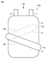
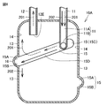
- FIG. It is a side view of the accumulator which concerns on Embodiment 1.
- FIG. It is a top view seen from the arrow III in FIG. It is sectional drawing seen from the line segment IV-IV in FIG. It is sectional drawing seen from the line segment VV in FIG. It is a side view of the accumulator which concerns on Embodiment 2.
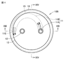
- FIG. It is a top view seen from the arrow VII in FIG. It is sectional drawing seen from the line segment VIII-VIII in FIG. 7. It is sectional drawing seen from the line segment IX-IX in FIG. It is a side view of the accumulator which concerns on Embodiment 3.
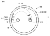
- FIG. 15 is a cross-sectional view perpendicular to the vertical direction of the accumulator shown in FIG. It is sectional drawing which shows the modification of the accumulator which concerns on Embodiment 1.
- FIG. 15 is a cross-sectional view perpendicular to the vertical direction of the accumulator shown in FIG. It is sectional drawing which shows the modification of the accumulator which concerns on Embodiment 1.
- the refrigerating cycle device 100 includes a refrigerant circuit in which a refrigerant circulates.
- the refrigerant circuit includes a compressor 101, a four-way valve 102 as a flow path switching unit, an outdoor heat exchanger 103, a decompression device 104, an indoor heat exchanger 105, and an accumulator 10.
- the refrigeration cycle device 100 is, for example, an air conditioner.
- the compressor 101 has a discharge port for discharging the refrigerant and a suction port for sucking the refrigerant.
- the pressure reducing device 104 is, for example, an expansion valve.
- the accumulator 10 has an inflow pipe 11 into which the refrigerant flows in and an outflow pipe 12 in which the refrigerant flows out.
- the outflow pipe 12 is connected to the discharge port of the compressor 101.
- the four-way valve 102 has a first port connected to the discharge port of the compressor 101, a second port connected to the inflow pipe 11 of the accumulator 10, and a third port connected to the outdoor heat exchanger 103. And a fourth port connected to the indoor heat exchanger 105.
- the four-way valve 102 has a first state in which the outdoor heat exchanger 103 acts as a condenser and the indoor heat exchanger 105 acts as an evaporator, and the indoor heat exchanger 105 acts as a condenser and the outdoor heat exchanger 103 evaporates. It is provided to switch between the second state, which acts as a vessel.
- the refrigerating cycle device 100 is an air conditioner
- the first state is realized during the cooling operation and the second state is realized during the heating operation.
- the accumulator 10 is arranged between the evaporator and the suction port of the compressor 101, and the direction in which the refrigerant flows in the accumulator 10 is constant.
- the accumulator 10 mainly includes an inflow pipe 11, an outflow pipe 12, and a container 13.
- the accumulator 10 is defined in the vertical direction, the circumferential direction, and the radial direction.
- the outflow pipe 12 is arranged above the container 13. That is, the vertical direction is the direction in which the outflow pipe 12 and the container 13 are arranged side by side.
- the circumferential direction is the direction in which the side surface portion of the container 13 extends when the accumulator 10 is viewed from above.
- the radial direction is a direction from the center of the container 13 toward the side surface when the accumulator 10 is viewed from above.
- the dotted arrow 201 indicates the flow direction of the gas phase refrigerant
- the solid arrow 202 indicates the flow direction of the liquid phase refrigerant.
- the inflow pipe 11 is a pipe for the gas-phase refrigerant or the gas-liquid two-phase refrigerant flowing out of the evaporator to flow into the container 13.
- the inflow pipe 11 has a first open end 11E arranged in the container 13.
- the inflow pipe 11 is, for example, a first pipe portion 11A extending in the vertical direction and penetrating the upper surface portion of the container 13, and a first pipe portion 11A connected to the lower end of the first pipe portion 11A and extending in a direction intersecting the vertical direction. It has two pipe portions 11B.
- the inflow pipe 11 has a bent portion in the container 13.
- the second pipe portion 11B has the first opening end 11E.
- the inflow pipe 11 may penetrate the side surface portion of the container 13, for example.
- the outflow pipe 12 is a pipe for the gas phase refrigerant in the container 13 to flow out to the suction port of the compressor 101.
- the outflow pipe 12 has a second open end 12E disposed in the container 13.
- the outflow pipe 12 is formed symmetrically with the first pipe portion 11A of the inflow pipe 11 with respect to the central axis extending in the vertical direction of the container 13, for example.
- the first opening end 11E and the second opening end 12E are arranged between the upper surface portion and the lower surface portion of the container 13 in the vertical direction.
- the first opening end 11E is such that the second opening end 12E of the container 13 is arranged above the first opening end 11E, for example.
- the first opening end 11E faces outward with respect to the central axis.
- the second opening end 12E faces downward, for example.
- the container 13 is a tubular body, for example, a cylindrical body.
- the container 13 includes an inner peripheral surface 14 extending in the vertical direction and the circumferential direction, and a concave surface 15 recessed with respect to the inner peripheral surface 14 and extending along the circumferential direction.
- the concave surface 15 is formed so as to be continuous over the entire circumference, for example, in the circumferential direction.
- the concave surface 15 is formed above, for example, the vertical center of the container 13.
- the concave surface 15 is arranged above the center of the inner peripheral surface 14 in the vertical direction.
- the inside of the container 13 in the refrigerant circuit and the outside of the accumulator 10 are connected only by, for example, the inflow pipe 11 and the outflow pipe 12.
- the concave surface 15 has a first inclined surface 15A that extends along the circumferential direction and inclines outward as it goes downward, and a first inclined surface 15A that extends along the circumferential direction and inclines downward. It has a second inclined surface 15B that inclines toward the inside.
- the first inclined surface 15A is arranged above the second inclined surface 15B.
- the lower end of the first inclined surface 15A is connected to the upper end of the second inclined surface 15B.
- the lower end of the first inclined surface 15A is in contact with the upper end of the second inclined surface 15B.
- the lower end of the first inclined surface 15A may be connected to the upper end of the second inclined surface 15B via an inner peripheral surface that extends in the vertical direction and the circumferential direction and has an inner diameter longer than that of the inner peripheral surface 14.
- each cross-sectional shape of the first inclined surface 15A and the second inclined surface 15B perpendicular to the circumferential direction is, for example, an arc shape.
- the cross-sectional shapes of the first inclined surface 15A and the second inclined surface 15B perpendicular to the circumferential direction are symmetrical with respect to the vertical center of the concave surface 15, for example.
- the connection portion between the lower end of the first inclined surface 15A and the upper end of the second inclined surface 15B is arranged, for example, at the center of the concave surface 15 in the vertical direction.
- the cross-sectional shape of the concave surface 15 perpendicular to the circumferential direction is, for example, C-shaped, U-shaped, or semicircular.
- the cross-sectional shapes of the first inclined surface 15A and the second inclined surface 15B perpendicular to the circumferential direction may be, for example, linear.
- the cross-sectional shape of the concave surface 15 perpendicular to the circumferential direction may be, for example, V-shaped.
- a part of the concave surface 15 in the circumferential direction is arranged so as to face the first opening end 11E.
- a part of each of the first inclined surface 15A and the second inclined surface 15B in the circumferential direction is arranged so as to face the first opening end 11E.
- a virtual straight line C (see FIG. 5) extending through the center of the first opening end 11E and along a direction perpendicular to the first opening end 11E intersects a part of the circumferential direction of the concave surface 15.
- the virtual straight line C intersects, for example, the center of a part of the concave surface 15 in the circumferential direction in the vertical direction.
- the virtual straight line C intersects a part of the circumferential direction of the connection portion between the lower end of the first inclined surface 15A and the upper end of the second inclined surface 15B, for example.
- the virtual straight line C is, for example, along the horizontal direction.
- the first inclined surface 15A of the concave surface 15 is arranged below the second opening end 12E.
- the second open end 12E is arranged above the first inclined surface 15A of the concave surface 15.
- the vertical width of the concave surface 15 is wider than the maximum width of the first opening end 11E.
- the vertical widths of the first inclined surface 15A and the second inclined surface 15B are narrower than, for example, the maximum width of the first opening end 11E.
- the concave surface 15 is arranged outside the outer peripheral surface located on the side opposite to the inner peripheral surface 14 in the radial direction.
- the radial width of the concave surface 15 is, for example, wider than half the maximum width of the first opening end 11E.
- the radial width of the concave surface 15 is, for example, wider than half the maximum width of the first opening end 11E.
- the concave surface 15 is formed as, for example, the inner peripheral surface of the convex portion 16 projecting from the outer peripheral surface of the container 13.
- the gas-liquid two-phase refrigerant flows into the container 13 from the first opening end 11E of the inflow pipe 11.
- the gas-liquid two-phase refrigerant flowing into the container 13 collides with a part of the concave surface 15 arranged so as to face the first opening end 11E in the circumferential direction, and then receives centrifugal force in the circumferential direction on the concave surface 15.
- the gas-liquid two-phase refrigerant includes a gas-phase refrigerant and a liquid-phase refrigerant existing as droplets in the gas-phase refrigerant.
- the liquid phase refrigerant flowing in the circumferential direction on the first inclined surface 15A gradually moves downward due to the action of centrifugal force and gravity, and reaches the lower end of the first inclined surface 15A. Since the flow velocity of the liquid phase refrigerant decreases while flowing through the concave surface 15, the centrifugal force acting on the liquid phase refrigerant gradually decreases. As a result, the liquid phase refrigerant flowing along the circumferential direction on the first inclined surface 15A finally reaches the second inclined surface 15B under the action of gravity.
- the liquid phase refrigerant that collided with the second inclined surface 15B facing the first opening end 11E and the liquid phase refrigerant that flowed from the first inclined surface 15A to the second inclined surface 15B are subjected to a relatively large centrifugal force while receiving a relatively large centrifugal force. It flows in the circumferential direction on the second inclined surface 15B, but moves downward as the flow velocity decreases, and finally reaches the inner peripheral surface 14 arranged below the second inclined surface 15B under the action of gravity.
- the liquid phase refrigerant that has reached the inner peripheral surface 14 goes downward along the inner peripheral surface 14 and stays in the container 13.
- the liquid-phase refrigerant existing as droplets is separated and removed from the gas-liquid two-phase refrigerant, and only the gas-phase refrigerant flows out of the accumulator 10 from the outflow pipe 12.
- the accumulator 10 can suppress the outflow of the liquid phase refrigerant while having a relatively simple configuration.
- the droplet is disposed at the second opening end as compared with the case where the second opening end 12E is arranged below the concave surface 15. It is difficult to flow into 12E.
- the refrigeration cycle device 100 provided with the accumulator 10, the outflow of the liquid phase refrigerant from the accumulator 10 to the compressor 101 is suppressed. Therefore, the refrigerating machine oil in the compressor 101 is difficult to be diluted by the liquid phase refrigerant, and seizure of the sliding portion of the compressor 101 is suppressed. As a result, the refrigeration cycle device 100 has high reliability.
- Embodiment 2 As shown in FIGS. 6 to 9, the accumulator 10A according to the second embodiment has basically the same configuration as the accumulator 10 according to the first embodiment, but the concave surface 15 is formed in a spiral shape. In that respect, it differs from the accumulator 10.
- the concave surface 15 is formed so as to be connected to the first portion 15C and the first portion 15C which are arranged so as to face the first opening end 11E and to be directed downward as the distance from the first portion 15C in the circumferential direction. It includes a second portion 15D that is connected to the second portion 15D and a third portion 15E that is formed so as to move downward from the lower end of the second portion 15D in the circumferential direction.
- Each of the first portion 15C, the second portion 15D, and the third portion 15E has a first inclined surface 15A and a second inclined surface 15B.
- Each of the first inclined surface 15A and the second inclined surface 15B is continuous in the first portion 15C, the second portion 15D, and the third portion 15E.
- each of the first portion 15C and the third portion 15E is gently inclined inward toward the end in the circumferential direction, and the inner peripheral surface is gradually inclined. It is connected to 14.
- the inclination angle ⁇ formed by the first portion 15C with respect to the tangent line of the inner peripheral surface 14 passing through the connection portion between the first portion 15C and the inner peripheral surface 14 is larger than 0 degrees and larger than 90 degrees. small.
- the lower end of the third portion 15E is arranged at intervals in the circumferential direction from, for example, the first portion 15C of the concave surface 15.
- the third portion 15E may be arranged so as to overlap the first portion 15C of the concave surface 15, for example.
- the accumulator 10A Since the accumulator 10A has basically the same configuration as the accumulator 10, it can exert the same effect as the accumulator 10.
- the liquid-phase refrigerant flows downward due to the action of centrifugal force in addition to the action of gravity, so that the efficiency of gas-liquid separation is higher than that of the accumulator 10.
- the accumulator 10B according to the third embodiment has basically the same configuration as the accumulator 10 according to the first embodiment, but the inflow pipe 11 has a concave surface 15 in the container 13. It differs from the accumulator 10 in that it includes a curved tube portion 11C extending along the accumulator 10.
- the curved pipe portion 11C is composed of, for example, at least a part of the second pipe portion 11B.
- the curved tube portion 11C has a first opening end 11E. As shown in FIGS. 11 and 12, when viewed from above and below, the first opening end 11E is arranged, for example, along the radial direction of the container 13.
- the inner peripheral surface of the curved tube portion 11C has a portion located inside the radial direction and a portion located outside the radial direction.
- the vertical width of the curved tube portion 11C is narrower than the vertical width of the concave surface 15.
- the vertical width of the curved pipe portion 11C is wider than, for example, the vertical widths of the first inclined surface 15A and the second inclined surface 15B.
- the portion of the first opening end 11E located on the outermost peripheral side in the radial direction is, for example, surrounded by a concave surface 15 and arranged in a space located outside the inner peripheral surface 14.
- the first opening end 11E When viewed from the vertical direction, the first opening end 11E is arranged, for example, between the outflow pipe 12 and the concave surface 15. When viewed from the vertical direction, the first opening end 11E is arranged side by side with, for example, the center of the outflow pipe 12 in the radial direction.
- the shortest distance between the portion of the first opening end 11E located on the outer peripheral side in the radial direction and the concave surface 15 is the distance between the portion of the first opening end 11E located on the outer peripheral side in the radial direction and the concave surface 15. Shorter than the shortest distance.
- the accumulator 10B Since the accumulator 10B has basically the same configuration as the accumulator 10, it can exert the same effect as the accumulator 10.
- the accumulator 10B gas-liquid separation is also performed in the curved pipe portion 11C of the inflow pipe 11 prior to the gas-liquid separation on the concave surface 15. Therefore, the accumulator 10B has a higher gas-liquid separation efficiency than the accumulator 10.
- the liquid phase refrigerant gradually flows outside in the radial direction due to the action of centrifugal force, and is located on the outer peripheral side in the radial direction of the first opening end 11E. It flows out from the portion to be discharged into the container 13.
- the gas phase refrigerant flows inside the liquid phase refrigerant in the radial direction due to the action of centrifugal force, and flows out into the container 13 from the portion of the first opening end 11E located on the inner peripheral side in the radial direction.
- the shortest distance between the portion of the first opening end 11E located on the outer peripheral side in the radial direction and the concave surface 15 is the distance between the portion of the first opening end 11E located on the outer peripheral side in the radial direction and the concave surface 15. Shorter than the shortest distance between. Therefore, the liquid phase refrigerant is more likely to collide with the concave surface 15 than the gas phase refrigerant. As a result, the accumulator 10B also promotes gas-liquid separation on the concave surface 15 as compared with the accumulator 10.
- the accumulator 10B has basically the same configuration as the accumulator 10A according to the second embodiment, and the inflow pipe 11 includes a curved pipe portion 11C extending along the concave surface 15 in the container 13. It may be different from 10A. That is, the concave surface 15 of the accumulator 10B may be formed in a spiral shape.
- the accumulator 10C according to the fourth embodiment has basically the same configuration as the accumulator 10B according to the third embodiment, but has a first opening end when viewed from above and below. It differs from the accumulator 10B in that 11E is inclined toward the concave surface 15 side with respect to the radial direction of the container 13.
- the inner peripheral portion 11E1 located on the innermost peripheral side in the radial direction of the first opening end 11E when viewed from the vertical direction is, for example, the center of the outflow pipe 12 and the diameter thereof. They are arranged side by side in the direction.
- the outer peripheral portion 11E2 located on the outermost peripheral side in the radial direction of the first opening end 11E when viewed from the vertical direction is arranged behind the inner peripheral portion 11E1 in the circumferential direction.
- the angle formed by the first opening end 11E and the outer peripheral surface of the curved tube portion 11C is an obtuse angle.
- the angle formed by the first opening end 11E and the inner peripheral surface of the curved tube portion 11C is an acute angle.
- the accumulator 10C Since the accumulator 10C has basically the same configuration as the accumulator 10B, it can exert the same effect as the accumulator 10B.
- the first opening end 11E is inclined toward the concave surface 15 side with respect to the radial direction of the container 13 when viewed from the vertical direction. Therefore, in the accumulator 10C, even when the liquid phase refrigerant flowing out from the outer peripheral portion 11E2 collides with the concave surface 15 and scatters, the inner peripheral portion 11E1 can suppress the scattering of droplets inward from the inner peripheral portion 11E1. .. As a result, the accumulator 10C also promotes gas-liquid separation on the concave surface 15 as compared with the accumulator 10B.
- the accumulator 10C has basically the same configuration as the accumulator 10A according to the second embodiment, and the inflow pipe 11 includes a curved pipe portion 11C extending along the concave surface 15 in the container 13. It may be different from 10A. That is, the concave surface 15 of the accumulator 10C may be formed in a spiral shape.
- a virtual straight line that passes through the center of the first opening end 11E and extends in the direction perpendicular to the first opening end 11E is along the horizontal direction.
- the virtual straight line C may be inclined with respect to the horizontal direction, for example.
- the first opening end 11E may face upward, for example, in the horizontal direction.
- the first opening end 11E is arranged so that, for example, the virtual straight line C intersects the first inclined surface 15A.
- the first opening end 11E may face downward, for example, in the horizontal direction.
- the first opening end 11E is arranged so that, for example, the virtual straight line C intersects the second inclined surface 15B.
- the curved tube portion 11C may be formed in a spiral shape.
- concave surface 15 is formed, but the present invention is not limited to this.
- a plurality of concave surfaces 15 may be formed on the accumulators 10 to 10C so as to be spaced apart from each other in the vertical direction.
- Each concave surface 15 may be configured as any concave surface 15 of the accumulators 10 to 10C.
Landscapes
- Engineering & Computer Science (AREA)
- Chemical & Material Sciences (AREA)
- Chemical Kinetics & Catalysis (AREA)
- Analytical Chemistry (AREA)
- Power Engineering (AREA)
- Physics & Mathematics (AREA)
- Mechanical Engineering (AREA)
- Thermal Sciences (AREA)
- General Engineering & Computer Science (AREA)
- Compressor (AREA)
- Applications Or Details Of Rotary Compressors (AREA)
Priority Applications (5)
| Application Number | Priority Date | Filing Date | Title |
|---|---|---|---|
| CN202080100254.4A CN115516259A (zh) | 2020-05-11 | 2020-05-11 | 储蓄器和制冷循环装置 |
| US17/911,449 US20230106373A1 (en) | 2020-05-11 | 2020-05-11 | Accumulator and refrigeration cycle apparatus |
| PCT/JP2020/018845 WO2021229649A1 (ja) | 2020-05-11 | 2020-05-11 | アキュムレータおよび冷凍サイクル装置 |
| JP2022522108A JP7361907B2 (ja) | 2020-05-11 | 2020-05-11 | アキュムレータおよび冷凍サイクル装置 |
| EP20935970.2A EP4151928A4 (en) | 2020-05-11 | 2020-05-11 | Accumulator and refrigeration cycle device |
Applications Claiming Priority (1)
| Application Number | Priority Date | Filing Date | Title |
|---|---|---|---|
| PCT/JP2020/018845 WO2021229649A1 (ja) | 2020-05-11 | 2020-05-11 | アキュムレータおよび冷凍サイクル装置 |
Publications (1)
| Publication Number | Publication Date |
|---|---|
| WO2021229649A1 true WO2021229649A1 (ja) | 2021-11-18 |
Family
ID=78526223
Family Applications (1)
| Application Number | Title | Priority Date | Filing Date |
|---|---|---|---|
| PCT/JP2020/018845 Ceased WO2021229649A1 (ja) | 2020-05-11 | 2020-05-11 | アキュムレータおよび冷凍サイクル装置 |
Country Status (5)
| Country | Link |
|---|---|
| US (1) | US20230106373A1 (https=) |
| EP (1) | EP4151928A4 (https=) |
| JP (1) | JP7361907B2 (https=) |
| CN (1) | CN115516259A (https=) |
| WO (1) | WO2021229649A1 (https=) |
Cited By (1)
| Publication number | Priority date | Publication date | Assignee | Title |
|---|---|---|---|---|
| WO2024116757A1 (ja) * | 2022-11-30 | 2024-06-06 | 株式会社アイシン | マニホールド |
Citations (4)
| Publication number | Priority date | Publication date | Assignee | Title |
|---|---|---|---|---|
| JPH1062037A (ja) * | 1996-08-21 | 1998-03-06 | Mitsubishi Electric Corp | アキュムレータ |
| JP2007093121A (ja) * | 2005-09-29 | 2007-04-12 | Denso Corp | 冷凍サイクル用気液分離器 |
| JP2010260026A (ja) * | 2009-05-11 | 2010-11-18 | Kobe Steel Ltd | 気液分離器 |
| JP2014088990A (ja) | 2012-10-30 | 2014-05-15 | Fuji Koki Corp | アキュムレータ |
Family Cites Families (17)
| Publication number | Priority date | Publication date | Assignee | Title |
|---|---|---|---|---|
| JPS56157775A (en) * | 1980-05-09 | 1981-12-05 | Hitachi Ltd | Refrigeration cycle for air conditioner |
| US5282370A (en) * | 1992-05-07 | 1994-02-01 | Fayette Tubular Technology Corporation | Air-conditioning system accumulator and method of making same |
| JPH07301467A (ja) * | 1994-05-06 | 1995-11-14 | Kubota Corp | 複段ヒートポンプ装置 |
| JP2001124442A (ja) * | 1999-10-27 | 2001-05-11 | Mitsubishi Electric Corp | アキューム・レシーバおよびその製造方法 |
| KR100390779B1 (ko) * | 2000-10-19 | 2003-07-10 | 주식회사 엘지이아이 | 밀폐형 압축기의 어큐뮬레이터구조 |
| JP2004077033A (ja) * | 2002-08-20 | 2004-03-11 | Mitsubishi Electric Corp | 遠心分離式の油分離器、遠心分離式の油分離器の製造方法 |
| JP2006226603A (ja) * | 2005-02-17 | 2006-08-31 | Calsonic Kansei Corp | アキュームレータ |
| JP2007192433A (ja) * | 2006-01-17 | 2007-08-02 | Daikin Ind Ltd | 気液分離器及び該気液分離器を備えた冷凍装置 |
| JP2011094946A (ja) * | 2009-09-30 | 2011-05-12 | Daikin Industries Ltd | ガス冷媒分離器、ガス冷媒分離兼冷媒分流器、膨張弁及び冷凍装置 |
| JP5520800B2 (ja) * | 2010-12-17 | 2014-06-11 | 株式会社神戸製鋼所 | 油分離器 |
| JP2014044006A (ja) * | 2012-08-27 | 2014-03-13 | Kobe Steel Ltd | 油分離器及び圧縮装置 |
| CN204285911U (zh) * | 2014-12-08 | 2015-04-22 | 天津市天元机械制造有限公司 | 立式气液分离器 |
| KR20180095768A (ko) * | 2017-02-18 | 2018-08-28 | 도요이엔에스 주식회사 | 히트 펌프 시스템에 있어서의 유체 교반장치 |
| ES2904309T3 (es) * | 2017-09-28 | 2022-04-04 | Mitsubishi Electric Corp | Separador de aceite y acondicionador de aire con el mismo |
| KR102143761B1 (ko) * | 2018-10-11 | 2020-08-12 | 엘지전자 주식회사 | 리시버 일체형 어큐뮬레이터 |
| CN109539643A (zh) * | 2018-11-05 | 2019-03-29 | 广东美的暖通设备有限公司 | 一种气液分离器以及空调器 |
| CN209985054U (zh) * | 2019-04-30 | 2020-01-24 | 廊坊中建机械有限公司 | 缓冲罐及除尘系统 |
-
2020
- 2020-05-11 EP EP20935970.2A patent/EP4151928A4/en not_active Withdrawn
- 2020-05-11 CN CN202080100254.4A patent/CN115516259A/zh active Pending
- 2020-05-11 WO PCT/JP2020/018845 patent/WO2021229649A1/ja not_active Ceased
- 2020-05-11 JP JP2022522108A patent/JP7361907B2/ja active Active
- 2020-05-11 US US17/911,449 patent/US20230106373A1/en not_active Abandoned
Patent Citations (4)
| Publication number | Priority date | Publication date | Assignee | Title |
|---|---|---|---|---|
| JPH1062037A (ja) * | 1996-08-21 | 1998-03-06 | Mitsubishi Electric Corp | アキュムレータ |
| JP2007093121A (ja) * | 2005-09-29 | 2007-04-12 | Denso Corp | 冷凍サイクル用気液分離器 |
| JP2010260026A (ja) * | 2009-05-11 | 2010-11-18 | Kobe Steel Ltd | 気液分離器 |
| JP2014088990A (ja) | 2012-10-30 | 2014-05-15 | Fuji Koki Corp | アキュムレータ |
Cited By (1)
| Publication number | Priority date | Publication date | Assignee | Title |
|---|---|---|---|---|
| WO2024116757A1 (ja) * | 2022-11-30 | 2024-06-06 | 株式会社アイシン | マニホールド |
Also Published As
| Publication number | Publication date |
|---|---|
| US20230106373A1 (en) | 2023-04-06 |
| CN115516259A (zh) | 2022-12-23 |
| EP4151928A4 (en) | 2023-06-14 |
| EP4151928A1 (en) | 2023-03-22 |
| JP7361907B2 (ja) | 2023-10-16 |
| JPWO2021229649A1 (https=) | 2021-11-18 |
Similar Documents
| Publication | Publication Date | Title |
|---|---|---|
| US20170276415A1 (en) | Oil separator | |
| KR20020070965A (ko) | 오일분리기 및 그것을 구비한 실외기 | |
| JP2011202876A (ja) | 遠心分離式油分離器及び空気調和装置の室外機 | |
| JP2008196721A (ja) | 気液分離器 | |
| JP2015034637A (ja) | 気液分離器および冷凍サイクル装置 | |
| CN103245144B (zh) | 节能器及冷冻机 | |
| JP6827554B2 (ja) | 油分離器およびそれを備えた空気調和機 | |
| WO2021229649A1 (ja) | アキュムレータおよび冷凍サイクル装置 | |
| WO2020195711A1 (ja) | 液分離器、冷却システム及び気液分離方法 | |
| JP2008032269A (ja) | アキュムレータ | |
| JP2010048483A (ja) | 気液分離器並びにこれを搭載した空気圧縮装置および空気調和装置 | |
| JP2009019781A (ja) | 熱交換器 | |
| JP6296322B2 (ja) | オイルセパレータ | |
| JP7430759B2 (ja) | アキュムレータ及び冷凍サイクル | |
| US20250123038A1 (en) | Refrigerant storage container and refrigeration cycle apparatus provided with the same | |
| JP2006266524A (ja) | アキュムレータ | |
| KR20070099759A (ko) | 냉방장치의 기액분리기 | |
| EP4339536A1 (en) | Refrigerant storage container, and refrigeration cycle device provided with said refrigerant storage container | |
| JP6878550B2 (ja) | 冷凍装置 | |
| JPWO2021229649A5 (https=) | ||
| JP2014196855A (ja) | 油分離器および冷凍サイクル装置の室外ユニット | |
| CN115485517B (zh) | 蒸发器 | |
| JP2009052771A (ja) | 熱交換器 | |
| JP2016003825A (ja) | 気液分離器 | |
| JP2009030930A (ja) | 熱交換器 |
Legal Events
| Date | Code | Title | Description |
|---|---|---|---|
| 121 | Ep: the epo has been informed by wipo that ep was designated in this application |
Ref document number: 20935970 Country of ref document: EP Kind code of ref document: A1 |
|
| ENP | Entry into the national phase |
Ref document number: 2022522108 Country of ref document: JP Kind code of ref document: A |
|
| NENP | Non-entry into the national phase |
Ref country code: DE |
|
| ENP | Entry into the national phase |
Ref document number: 2020935970 Country of ref document: EP Effective date: 20221212 |