WO2021220935A1 - ガスバリアフィルム - Google Patents
ガスバリアフィルム Download PDFInfo
- Publication number
- WO2021220935A1 WO2021220935A1 PCT/JP2021/016307 JP2021016307W WO2021220935A1 WO 2021220935 A1 WO2021220935 A1 WO 2021220935A1 JP 2021016307 W JP2021016307 W JP 2021016307W WO 2021220935 A1 WO2021220935 A1 WO 2021220935A1
- Authority
- WO
- WIPO (PCT)
- Prior art keywords
- layer
- gas barrier
- barrier film
- thickness
- resin layer
- Prior art date
- Legal status (The legal status is an assumption and is not a legal conclusion. Google has not performed a legal analysis and makes no representation as to the accuracy of the status listed.)
- Ceased
Links
Images


Classifications
-
- B—PERFORMING OPERATIONS; TRANSPORTING
- B65—CONVEYING; PACKING; STORING; HANDLING THIN OR FILAMENTARY MATERIAL
- B65D—CONTAINERS FOR STORAGE OR TRANSPORT OF ARTICLES OR MATERIALS, e.g. BAGS, BARRELS, BOTTLES, BOXES, CANS, CARTONS, CRATES, DRUMS, JARS, TANKS, HOPPERS, FORWARDING CONTAINERS; ACCESSORIES, CLOSURES, OR FITTINGS THEREFOR; PACKAGING ELEMENTS; PACKAGES
- B65D75/00—Packages comprising articles or materials partially or wholly enclosed in strips, sheets, blanks, tubes or webs of flexible sheet material, e.g. in folded wrappers
- B65D75/52—Details
- B65D75/58—Opening or contents-removing devices added or incorporated during package manufacture
- B65D75/5861—Spouts
- B65D75/5872—Non-integral spouts
- B65D75/5883—Non-integral spouts connected to the package at the sealed junction of two package walls
-
- B—PERFORMING OPERATIONS; TRANSPORTING
- B32—LAYERED PRODUCTS
- B32B—LAYERED PRODUCTS, i.e. PRODUCTS BUILT-UP OF STRATA OF FLAT OR NON-FLAT, e.g. CELLULAR OR HONEYCOMB, FORM
- B32B1/00—Layered products having a non-planar shape
- B32B1/08—Tubular products
-
- B—PERFORMING OPERATIONS; TRANSPORTING
- B32—LAYERED PRODUCTS
- B32B—LAYERED PRODUCTS, i.e. PRODUCTS BUILT-UP OF STRATA OF FLAT OR NON-FLAT, e.g. CELLULAR OR HONEYCOMB, FORM
- B32B27/00—Layered products comprising a layer of synthetic resin
- B32B27/06—Layered products comprising a layer of synthetic resin as the main or only constituent of a layer, which is next to another layer of the same or of a different material
- B32B27/08—Layered products comprising a layer of synthetic resin as the main or only constituent of a layer, which is next to another layer of the same or of a different material of synthetic resin
-
- B—PERFORMING OPERATIONS; TRANSPORTING
- B32—LAYERED PRODUCTS
- B32B—LAYERED PRODUCTS, i.e. PRODUCTS BUILT-UP OF STRATA OF FLAT OR NON-FLAT, e.g. CELLULAR OR HONEYCOMB, FORM
- B32B27/00—Layered products comprising a layer of synthetic resin
- B32B27/32—Layered products comprising a layer of synthetic resin comprising polyolefins
-
- B—PERFORMING OPERATIONS; TRANSPORTING
- B65—CONVEYING; PACKING; STORING; HANDLING THIN OR FILAMENTARY MATERIAL
- B65D—CONTAINERS FOR STORAGE OR TRANSPORT OF ARTICLES OR MATERIALS, e.g. BAGS, BARRELS, BOTTLES, BOXES, CANS, CARTONS, CRATES, DRUMS, JARS, TANKS, HOPPERS, FORWARDING CONTAINERS; ACCESSORIES, CLOSURES, OR FITTINGS THEREFOR; PACKAGING ELEMENTS; PACKAGES
- B65D35/00—Pliable tubular containers adapted to be permanently or temporarily deformed to expel contents, e.g. collapsible tubes for toothpaste or other plastic or semi-liquid material; Holders therefor
- B65D35/02—Body construction
- B65D35/04—Body construction made in one piece
- B65D35/08—Body construction made in one piece from plastics material
-
- B—PERFORMING OPERATIONS; TRANSPORTING
- B65—CONVEYING; PACKING; STORING; HANDLING THIN OR FILAMENTARY MATERIAL
- B65D—CONTAINERS FOR STORAGE OR TRANSPORT OF ARTICLES OR MATERIALS, e.g. BAGS, BARRELS, BOTTLES, BOXES, CANS, CARTONS, CRATES, DRUMS, JARS, TANKS, HOPPERS, FORWARDING CONTAINERS; ACCESSORIES, CLOSURES, OR FITTINGS THEREFOR; PACKAGING ELEMENTS; PACKAGES
- B65D65/00—Wrappers or flexible covers; Packaging materials of special type or form
- B65D65/38—Packaging materials of special type or form
- B65D65/40—Applications of laminates for particular packaging purposes
-
- C—CHEMISTRY; METALLURGY
- C09—DYES; PAINTS; POLISHES; NATURAL RESINS; ADHESIVES; COMPOSITIONS NOT OTHERWISE PROVIDED FOR; APPLICATIONS OF MATERIALS NOT OTHERWISE PROVIDED FOR
- C09D—COATING COMPOSITIONS, e.g. PAINTS, VARNISHES OR LACQUERS; FILLING PASTES; CHEMICAL PAINT OR INK REMOVERS; INKS; CORRECTING FLUIDS; WOODSTAINS; PASTES OR SOLIDS FOR COLOURING OR PRINTING; USE OF MATERIALS THEREFOR
- C09D183/00—Coating compositions based on macromolecular compounds obtained by reactions forming in the main chain of the macromolecule a linkage containing silicon, with or without sulfur, nitrogen, oxygen, or carbon only; Coating compositions based on derivatives of such polymers
- C09D183/02—Polysilicates
-
- C—CHEMISTRY; METALLURGY
- C09—DYES; PAINTS; POLISHES; NATURAL RESINS; ADHESIVES; COMPOSITIONS NOT OTHERWISE PROVIDED FOR; APPLICATIONS OF MATERIALS NOT OTHERWISE PROVIDED FOR
- C09D—COATING COMPOSITIONS, e.g. PAINTS, VARNISHES OR LACQUERS; FILLING PASTES; CHEMICAL PAINT OR INK REMOVERS; INKS; CORRECTING FLUIDS; WOODSTAINS; PASTES OR SOLIDS FOR COLOURING OR PRINTING; USE OF MATERIALS THEREFOR
- C09D183/00—Coating compositions based on macromolecular compounds obtained by reactions forming in the main chain of the macromolecule a linkage containing silicon, with or without sulfur, nitrogen, oxygen, or carbon only; Coating compositions based on derivatives of such polymers
- C09D183/04—Polysiloxanes
- C09D183/06—Polysiloxanes containing silicon bound to oxygen-containing groups
-
- B—PERFORMING OPERATIONS; TRANSPORTING
- B32—LAYERED PRODUCTS
- B32B—LAYERED PRODUCTS, i.e. PRODUCTS BUILT-UP OF STRATA OF FLAT OR NON-FLAT, e.g. CELLULAR OR HONEYCOMB, FORM
- B32B2250/00—Layers arrangement
- B32B2250/02—2 layers
-
- B—PERFORMING OPERATIONS; TRANSPORTING
- B32—LAYERED PRODUCTS
- B32B—LAYERED PRODUCTS, i.e. PRODUCTS BUILT-UP OF STRATA OF FLAT OR NON-FLAT, e.g. CELLULAR OR HONEYCOMB, FORM
- B32B2250/00—Layers arrangement
- B32B2250/24—All layers being polymeric
- B32B2250/242—All polymers belonging to those covered by group B32B27/32
-
- B—PERFORMING OPERATIONS; TRANSPORTING
- B32—LAYERED PRODUCTS
- B32B—LAYERED PRODUCTS, i.e. PRODUCTS BUILT-UP OF STRATA OF FLAT OR NON-FLAT, e.g. CELLULAR OR HONEYCOMB, FORM
- B32B2250/00—Layers arrangement
- B32B2250/24—All layers being polymeric
- B32B2250/246—All polymers belonging to those covered by groups B32B27/32 and B32B27/30
-
- B—PERFORMING OPERATIONS; TRANSPORTING
- B32—LAYERED PRODUCTS
- B32B—LAYERED PRODUCTS, i.e. PRODUCTS BUILT-UP OF STRATA OF FLAT OR NON-FLAT, e.g. CELLULAR OR HONEYCOMB, FORM
- B32B2255/00—Coating on the layer surface
- B32B2255/10—Coating on the layer surface on synthetic resin layer or on natural or synthetic rubber layer
-
- B—PERFORMING OPERATIONS; TRANSPORTING
- B32—LAYERED PRODUCTS
- B32B—LAYERED PRODUCTS, i.e. PRODUCTS BUILT-UP OF STRATA OF FLAT OR NON-FLAT, e.g. CELLULAR OR HONEYCOMB, FORM
- B32B2255/00—Coating on the layer surface
- B32B2255/20—Inorganic coating
-
- B—PERFORMING OPERATIONS; TRANSPORTING
- B32—LAYERED PRODUCTS
- B32B—LAYERED PRODUCTS, i.e. PRODUCTS BUILT-UP OF STRATA OF FLAT OR NON-FLAT, e.g. CELLULAR OR HONEYCOMB, FORM
- B32B2255/00—Coating on the layer surface
- B32B2255/26—Polymeric coating
-
- B—PERFORMING OPERATIONS; TRANSPORTING
- B32—LAYERED PRODUCTS
- B32B—LAYERED PRODUCTS, i.e. PRODUCTS BUILT-UP OF STRATA OF FLAT OR NON-FLAT, e.g. CELLULAR OR HONEYCOMB, FORM
- B32B2255/00—Coating on the layer surface
- B32B2255/28—Multiple coating on one surface
-
- B—PERFORMING OPERATIONS; TRANSPORTING
- B32—LAYERED PRODUCTS
- B32B—LAYERED PRODUCTS, i.e. PRODUCTS BUILT-UP OF STRATA OF FLAT OR NON-FLAT, e.g. CELLULAR OR HONEYCOMB, FORM
- B32B2270/00—Resin or rubber layer containing a blend of at least two different polymers
-
- B—PERFORMING OPERATIONS; TRANSPORTING
- B32—LAYERED PRODUCTS
- B32B—LAYERED PRODUCTS, i.e. PRODUCTS BUILT-UP OF STRATA OF FLAT OR NON-FLAT, e.g. CELLULAR OR HONEYCOMB, FORM
- B32B2307/00—Properties of the layers or laminate
- B32B2307/70—Other properties
- B32B2307/724—Permeability to gases, adsorption
- B32B2307/7242—Non-permeable
-
- B—PERFORMING OPERATIONS; TRANSPORTING
- B32—LAYERED PRODUCTS
- B32B—LAYERED PRODUCTS, i.e. PRODUCTS BUILT-UP OF STRATA OF FLAT OR NON-FLAT, e.g. CELLULAR OR HONEYCOMB, FORM
- B32B2307/00—Properties of the layers or laminate
- B32B2307/70—Other properties
- B32B2307/724—Permeability to gases, adsorption
- B32B2307/7242—Non-permeable
- B32B2307/7244—Oxygen barrier
-
- B—PERFORMING OPERATIONS; TRANSPORTING
- B32—LAYERED PRODUCTS
- B32B—LAYERED PRODUCTS, i.e. PRODUCTS BUILT-UP OF STRATA OF FLAT OR NON-FLAT, e.g. CELLULAR OR HONEYCOMB, FORM
- B32B2307/00—Properties of the layers or laminate
- B32B2307/70—Other properties
- B32B2307/732—Dimensional properties
-
- B—PERFORMING OPERATIONS; TRANSPORTING
- B32—LAYERED PRODUCTS
- B32B—LAYERED PRODUCTS, i.e. PRODUCTS BUILT-UP OF STRATA OF FLAT OR NON-FLAT, e.g. CELLULAR OR HONEYCOMB, FORM
- B32B2311/00—Metals, their alloys or their compounds
- B32B2311/24—Aluminium
-
- B—PERFORMING OPERATIONS; TRANSPORTING
- B32—LAYERED PRODUCTS
- B32B—LAYERED PRODUCTS, i.e. PRODUCTS BUILT-UP OF STRATA OF FLAT OR NON-FLAT, e.g. CELLULAR OR HONEYCOMB, FORM
- B32B2323/00—Polyalkenes
- B32B2323/10—Polypropylene
-
- B—PERFORMING OPERATIONS; TRANSPORTING
- B32—LAYERED PRODUCTS
- B32B—LAYERED PRODUCTS, i.e. PRODUCTS BUILT-UP OF STRATA OF FLAT OR NON-FLAT, e.g. CELLULAR OR HONEYCOMB, FORM
- B32B2383/00—Polysiloxanes
-
- B—PERFORMING OPERATIONS; TRANSPORTING
- B32—LAYERED PRODUCTS
- B32B—LAYERED PRODUCTS, i.e. PRODUCTS BUILT-UP OF STRATA OF FLAT OR NON-FLAT, e.g. CELLULAR OR HONEYCOMB, FORM
- B32B2439/00—Containers; Receptacles
- B32B2439/02—Open containers
- B32B2439/06—Bags, sacks, sachets
-
- B—PERFORMING OPERATIONS; TRANSPORTING
- B32—LAYERED PRODUCTS
- B32B—LAYERED PRODUCTS, i.e. PRODUCTS BUILT-UP OF STRATA OF FLAT OR NON-FLAT, e.g. CELLULAR OR HONEYCOMB, FORM
- B32B2439/00—Containers; Receptacles
- B32B2439/40—Closed containers
- B32B2439/46—Bags
-
- B—PERFORMING OPERATIONS; TRANSPORTING
- B32—LAYERED PRODUCTS
- B32B—LAYERED PRODUCTS, i.e. PRODUCTS BUILT-UP OF STRATA OF FLAT OR NON-FLAT, e.g. CELLULAR OR HONEYCOMB, FORM
- B32B2439/00—Containers; Receptacles
- B32B2439/70—Food packaging
-
- C—CHEMISTRY; METALLURGY
- C08—ORGANIC MACROMOLECULAR COMPOUNDS; THEIR PREPARATION OR CHEMICAL WORKING-UP; COMPOSITIONS BASED THEREON
- C08G—MACROMOLECULAR COMPOUNDS OBTAINED OTHERWISE THAN BY REACTIONS ONLY INVOLVING UNSATURATED CARBON-TO-CARBON BONDS
- C08G77/00—Macromolecular compounds obtained by reactions forming a linkage containing silicon with or without sulfur, nitrogen, oxygen or carbon in the main chain of the macromolecule
- C08G77/02—Polysilicates
-
- C—CHEMISTRY; METALLURGY
- C08—ORGANIC MACROMOLECULAR COMPOUNDS; THEIR PREPARATION OR CHEMICAL WORKING-UP; COMPOSITIONS BASED THEREON
- C08G—MACROMOLECULAR COMPOUNDS OBTAINED OTHERWISE THAN BY REACTIONS ONLY INVOLVING UNSATURATED CARBON-TO-CARBON BONDS
- C08G77/00—Macromolecular compounds obtained by reactions forming a linkage containing silicon with or without sulfur, nitrogen, oxygen or carbon in the main chain of the macromolecule
- C08G77/04—Polysiloxanes
- C08G77/14—Polysiloxanes containing silicon bound to oxygen-containing groups
-
- Y—GENERAL TAGGING OF NEW TECHNOLOGICAL DEVELOPMENTS; GENERAL TAGGING OF CROSS-SECTIONAL TECHNOLOGIES SPANNING OVER SEVERAL SECTIONS OF THE IPC; TECHNICAL SUBJECTS COVERED BY FORMER USPC CROSS-REFERENCE ART COLLECTIONS [XRACs] AND DIGESTS
- Y02—TECHNOLOGIES OR APPLICATIONS FOR MITIGATION OR ADAPTATION AGAINST CLIMATE CHANGE
- Y02W—CLIMATE CHANGE MITIGATION TECHNOLOGIES RELATED TO WASTEWATER TREATMENT OR WASTE MANAGEMENT
- Y02W30/00—Technologies for solid waste management
- Y02W30/50—Reuse, recycling or recovery technologies
- Y02W30/80—Packaging reuse or recycling, e.g. of multilayer packaging
Definitions
- the present invention relates to a gas barrier film, and more particularly to a gas barrier film having resistance to heat sterilization such as boiling treatment and retort treatment.
- Gas barrier film is widely used as a packaging material for foods and pharmaceuticals, including heat sterilization such as boiling treatment and retort treatment. When packaging these contents, it has been particularly important to reduce the oxygen permeability.
- a barrier film used as a packaging material for such heat sterilization a polyethylene terephthalate film having high heat resistance is generally used as a base material.
- Patent Document 1 proposes a method of blending an ethylene- ⁇ -olefin copolymer with a polypropylene film
- Patent Documents 2 and 3 propose a method of laminating an ethylene- ⁇ -olefin copolymer or the like.
- the conventional gas barrier film cannot keep the oxygen permeability low even after the heat sterilization treatment.
- the present invention has been made in view of the above circumstances, and an object of the present invention is to provide a gas barrier film capable of suppressing the oxygen permeability to a low level even after heat sterilization treatment.
- the present invention comprises a base material layer containing polypropylene, a resin layer containing a copolymer of propylene and another monomer, a vapor-deposited layer of an inorganic oxide, and a gas barrier layer in this order, and the thickness of the vapor-deposited layer is increased. It is 5 to 300 nm, the thickness of the resin layer is 0.3 ⁇ m or more, and the softening temperature of the surface of the resin layer on the vapor deposition layer side is in the range of 100 ° C. to 170 ° C. as measured by local thermal analysis (LTA).
- LTA local thermal analysis
- Provided is at least one gas barrier film.
- the resin layer may contain a copolymer of propylene and ⁇ -olefin.
- the thickness of the resin layer may be 2.0 ⁇ m or less.
- the vapor-deposited layer may contain at least one selected from aluminum oxide and silicon oxide.
- the gas barrier layer is selected from Si (OR 1 ) 4 and R 2 Si (OR 3 ) 3 (OR 1 and OR 3 are independently hydrolyzable groups and R 2 is an organic functional group). It may be formed from a coating liquid containing at least one silicon compound or a hydrolyzate thereof and a water-soluble polymer having a hydroxyl group.
- the present invention also provides a packaging bag containing the gas barrier film according to the present invention.
- the present invention also provides a tube container containing the gas galia film according to the present invention.
- the present invention it is possible to provide a gas barrier film capable of suppressing the oxygen permeability to a low level even after heat sterilization treatment.
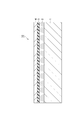
- FIG. 1 is a schematic cross-sectional view showing a gas barrier film according to an embodiment.
- the gas barrier film 10 according to the present embodiment includes a base material layer 1, a resin layer 2, a thin-film deposition layer 3, and a gas barrier layer 4 in this order.
- the base film is a support film (base film) and contains polypropylene.
- the polypropylene may be crystalline polypropylene, and from the viewpoint of further improving the heat resistance for heat sterilization, it is preferable to use homopolypropylene which is a homopolymer of propylene.
- a random copolymer of propylene and ⁇ -olefin or a mixture of the copolymer and homopolypropylene may be used as long as the effects of the present invention are not significantly impaired.
- the base material layer may be a film made of polypropylene, and polypropylene may be made into a sheet, and the sheet may be stretched by ordinary means to form a film oriented uniaxially or biaxially.
- Known additives such as antioxidants, stabilizers, lubricants such as calcium stearate, fatty acid amides and erucic acid amides, organic additives such as antistatic agents, silica, zeolites, siloids and hydrotals are used on the substrate layer.
- Inorganic additives such as site and particulate lubricant such as silicon particles may be added depending on the purpose.
- the thickness of the base material layer is not particularly limited, but may be, for example, 3 ⁇ m or more and 200 ⁇ m or less, and 6 ⁇ m or more and 50 ⁇ m or less.
- the resin layer contains a copolymer of propylene and other monomers.
- the above-mentioned base material layer shrinks due to heat.
- the vapor-deposited layer is destroyed by the shrinkage of the substrate layer during heat sterilization, causing barrier deterioration.
- it is considered that the stress applied to the vapor-deposited layer due to shrinkage can be relaxed by providing the resin layer, and as a result, the vapor-deposited layer is less likely to be destroyed.
- the resin layer may be made of a copolymer of propylene and another monomer.
- the other monomer for example, ⁇ -olefins such as ethylene, 1-butene and 1-hexene are preferably used.
- the resin layer needs to have at least one softening temperature on the surface on the vapor deposition layer side in the range of 100 ° C. to 170 ° C.
- the softening temperature is a temperature value obtained by local thermal analysis (LTA) and is an index showing the softening behavior.
- LTA local thermal analysis
- an atomic force microscope equipped with a nanothermal microscope composed of a cantilever having a heating mechanism is used. When the cantilever is brought into contact with the fixed sample surface fixed on the sample table, a constant force (tactile pressure) is applied to the cantilever in contact mode, and the sample surface is heated by applying a voltage, the sample surface expands thermally. Then the cantilever rises.
- the sample surface softens and a large change in hardness is observed, and the cantilever is processed and enters the sample surface.
- the sudden change in displacement at this time is detected.
- the point of change of this voltage is the softening point, and the softening temperature is calculated by converting the voltage into temperature.
- the atomic force microscope uses MPF-3D-SA (trade name) and Ztherm system (trade name) manufactured by Oxford Instruments Co., Ltd.
- the device is not particularly limited to this device, and can be measured by Bruker Japan's Nano Thermal Analysis (trade name) series and nanoIR (trade name) series. Furthermore, it is also possible to attach Nano Thermaml Analysis (trade name) as an accessory to another manufacturer AFM and measure it.
- the cantilever uses AN2-200 (trade name) manufactured by Anasis Instruments.
- the cantilever is not particularly limited, and another cantilever may be used as long as the laser beam can be sufficiently reflected and a voltage can be applied.
- the voltage range applied to the cantilever depends on the resin or the like to be measured, but is preferably 1 V to 10 V, causes less damage to the sample, and is more preferably 3 V to 8 V in order to measure with higher spatial resolution.
- the measurable softening temperature range depends on the resin to be measured, etc., but in general, the measurement start temperature can be measured from about 25 ° C at room temperature to the measurement end temperature of about 400 ° C.
- the temperature range for calculating the softening temperature is preferably 25 ° C. or higher and 300 ° C. or lower.
- the spring constant of the cantilever is preferably 0.1 to 3.5 N / m, and a cantilever with a spring constant of 0.5 to 3.5 N / m is used for measurement in both the tapping mode and the contact mode. Is preferable.
- the tactile pressure is preferably 0.1 to 3.0 V.
- the heating rate of the cantilever depends on the heating mechanism provided in the cantilever, but it is generally preferable to heat the cantilever at a heating rate of 0.1 V / sec or more and 10 V / sec or less. More preferably, it is heated at a heating rate of 0.2 V / sec or more and 5 V / sec or less.
- the amount of cantilever invaded is preferably 3 to 500 nm because a depth at which the peak top of the softening curve can be recognized is required. If the amount of penetration is large, the cantilever may be damaged, so it is more preferably 5 to 100 nm.
- a method of approximating the expansion curve and the softening curve by a function as required and calculating the intersection of these may be used to obtain the softening point and the softening temperature.
- an analysis method may be used in which the peak top of the displacement is the softening point or the softening temperature. In expansion or softening, it may be a displacement from a steady state to a certain value.
- a calibration curve may be created after the sample is measured.
- polycaprolactone melting point: 55 ° C
- low-density polyethylene LDPE, melting point: 110 ° C
- polypropylene PP, melting point: 164 ° C
- PET polyethylene terephthalate
- the softening temperature is 100 ° C. or higher, the heat resistance does not become too low, and there is little risk of softening during heat sterilization, resulting in deterioration of adhesion and barrier. Further, when the temperature is 150 ° C. or lower, the surface layer does not become too hard, the stress with other layers is relaxed when laminating or the like, the barrier layer is less likely to be destroyed, and there is less possibility of causing barrier deterioration. From such a viewpoint, the softening temperature is preferably 105 ° C. or higher, preferably 145 ° C. or lower, and more preferably 140 ° C. or lower.
- the copolymer ratio of the other monomers in the copolymer is preferably 2 to 10 mol%, more preferably 3 to 6 mol%.
- the copolymer ratio of the other monomers is 2 mol% or more, the adhesion to the vapor-deposited layer can be more sufficiently ensured. Further, when it is 10 mol% or less, the heat resistance of the resin layer is more sufficiently secured, and the decrease in adhesion can be suppressed during heat sterilization.
- the thickness of the resin layer is 0.3 ⁇ m or more.
- the thickness is preferably 0.5 ⁇ m or more.
- the upper limit of the thickness of the resin layer is not particularly limited, but is preferably 2.0 ⁇ m or less, more preferably 1.8 ⁇ m or less, from the viewpoint of more sufficiently ensuring the heat resistance of the entire base material. ..
- a recycled resin may be used, or a raw material derived from biomass such as a plant may be polymerized.
- Resin may be used. When these resins are used, they may be used alone or mixed with a resin polymerized from ordinary fossil fuels.
- the thin-film deposition layer is provided on the resin layer, for example, from the viewpoint of improving the gas barrier property against water vapor and oxygen, and is preferably transparent.
- the vapor-deposited layer contains an inorganic oxide, and as the inorganic oxide, for example, aluminum oxide, silicon oxide, tin oxide, magnesium oxide, or a mixture thereof can be used. Considering various sterilization resistances, it is more preferable to use at least one selected from aluminum oxide and silicon oxide.
- the thickness of the thin-film deposition layer of inorganic oxide is 5 to 300 nm.
- the thickness of the vapor-deposited layer is 5 nm or more, it is easy to obtain a film having a uniform and sufficient film thickness, and it is possible to sufficiently fulfill the function as a gas barrier film.
- the thickness of the vapor-deposited layer is 300 nm or less, flexibility can be imparted to the vapor-deposited layer, and cracks are less likely to occur in the vapor-deposited layer even if an external factor such as bending or tension is applied after the film formation.
- the thickness of the thin-film deposition layer is preferably 6 nm or more, preferably 150 nm or less, and more preferably 100 nm or less.
- the thin-film deposition layer can be formed by a normal vacuum vapor deposition method. Further, other thin film forming methods such as a sputtering method, an ion plating method, and a plasma vapor deposition method (CVD) can also be used. However, considering productivity, the vacuum deposition method is currently the best.
- the heating means of the vacuum vapor deposition method it is preferable to use any of an electron beam heating method, a resistance heating method, and an induction heating method, but considering the wide range of selectivity of the evaporative material, the electron beam heating method is used. Is more preferable.
- reaction vapor deposition in which various gases such as oxygen are blown into the vapor deposition may be used.
- surface treatment such as plasma treatment or corona treatment may be performed on the surface of the resin layer on the vapor-deposited layer side, and an anchor is provided between the resin layer and the vapor-deposited layer.
- a coat layer may be provided.
- the coating agent for providing the anchor coat layer include acrylic resin, epoxy resin, acrylic urethane resin, polyester polyurethane resin, and polyether polyurethane resin. Among these coating agents, acrylic urethane resin and polyester polyurethane resin are preferable from the viewpoint of heat resistance and interlayer adhesion strength.
- the gas barrier layer is provided for the purpose of protecting the vapor-deposited layer and complementing the barrier property.
- the gas barrier layer may be formed from a coating liquid containing a silicon compound or a hydrolyzate thereof and a water-soluble polymer having a hydroxyl group.
- water-soluble polymer having a hydroxyl group examples include polyvinyl alcohol, polyvinylpyrrolidone, starch, methyl cellulose, carboxymethyl cellulose, sodium alginate and the like.
- PVA polyvinyl alcohol
- the gas barrier property becomes more excellent, which is preferable.
- Examples of the silicon compound include Si (OR 1 ) 4 and R 2 Si (OR 3 ) 3 (OR 1 and OR 3 are independently hydrolyzable groups, and R 2 is an organic functional group). It is preferable that it is at least one selected from.
- Si (OR 1 ) 4 it is preferable to use tetraethoxysilane [Si (OC 2 H 5 ) 4]. Tetraethoxysilane is preferably used because it is relatively stable in an aqueous solvent after hydrolysis.
- R 2 Si (OR 3) 3 vinyl group as R 2 in an epoxy group, a methacryloxy group, a ureido group be selected from among isocyanate group.
- the gas barrier layer is obtained by mixing a water-soluble polymer dissolved in water or a water / alcohol mixed solvent with a treatment such as directly or in advance hydrolyzing a silicon compound, and applying this mixed solution to the vapor deposition layer. After coating on top, it is formed by heating and drying.
- Known additives such as isocyanate compounds, silane coupling agents, dispersants, stabilizers, viscosity modifiers, and colorants can be added to this solution as needed, as long as the gas barrier properties are not impaired. Is.
- the ratio of PVA in the mixed solution is preferably 20% by mass or more and 50% by mass or less, preferably 25% by mass, based on the total solid content of the mixed solution. It is more preferably 40% by mass or less.
- the proportion of PVA is 20% by mass or more, the flexibility of the film is maintained and the gas barrier layer is easily formed.
- the proportion of PVA is 50% by mass or less, sufficient gas barrier properties can be imparted by the gas barrier film.
- the packaging bag according to the present embodiment can be obtained by laminating a sealant layer on the gas barrier film described above via an adhesive layer to produce a packaging material, and then manufacturing the packaging material into a bag shape. ..
- a sealant layer for example, a stretched or unstretched polypropylene film may be used.
- the thickness of the sealant layer is not particularly limited, but may be, for example, 20 ⁇ m or more and 200 ⁇ m or less.
- the adhesive layer adheres the gas barrier film and the sealant layer.
- the adhesive constituting the adhesive layer include a polyurethane resin obtained by reacting a main agent such as a polyester polyol, a polyether polyol, an acrylic polyol, and a carbonate polyol with a bifunctional or higher functional isocyanate compound.
- a main agent such as a polyester polyol, a polyether polyol, an acrylic polyol, and a carbonate polyol with a bifunctional or higher functional isocyanate compound.
- the various polyols one type may be used alone or two or more types may be used in combination.
- a carbodiimide compound, an oxazoline compound, an epoxy compound, a phosphorus compound, a silane coupling agent, or the like may be blended with the above-mentioned polyurethane resin for the purpose of promoting adhesion.
- the coating amount of the adhesive layer may be, for example, 0.5 to 10 g / m 2 from the viewpoint of obtaining desired adhesive strength, followability, processability, and the like. From the viewpoint of environmental consideration, the adhesive layer may be one in which the polymer component is derived from biomass or one having biodegradability. Further, an adhesive having a barrier property may be used for the adhesive layer.
- the packaging bag may be formed into a bag shape by folding one packaging material in half so that the sealant layers face each other and then heat-sealing the three sides to form a bag shape.
- the bags may be formed into a bag shape by heat-sealing the four sides after stacking them so as to face each other.
- the packaging bag can contain the contents such as foods and pharmaceuticals as the contents. Further, the packaging bag may have a shape having a bent portion (bent portion) such as a standing pouch.
- the packaging bag according to the present embodiment can maintain high bath barrier properties even if it has a bent portion.
- Another form of the packaging bag is a packaging bag with a spout.
- the structure of the packaging bag with a spout is such that the spout is sandwiched between the two gas barrier films that form the packaging bag and fixed, or a hole is made in one side of the packaging bag and the spout is bonded and fixed.
- the spout may be provided on the upper surface of the packaging bag, diagonally above the packaging bag, or on the side surface or bottom surface of the packaging bag.
- a straw that reaches the bottom of the container may be provided in addition to the spout plug (so-called spout) so that the food can be sucked out by directly attaching the mouth.
- FIG. 2 is a perspective view showing an embodiment of a packaging bag with a spout (gusset bag with a spout).
- the packaging bag 100 with a spout shown in FIG. 2 has a structure in which the spout 104 is sandwiched and fixed to the seal portion 130 of the gas barrier film forming the packaging bag 140, and the spout 104 reaches the bottom of the container. A straw 105 is provided. Further, the packaging bag 100 with a spout can be sealed by closing the spout cap 104a.
- the packaging bag 140 constituting the packaging bag 100 with a spout may be a gusset bag that can stand on its own by expanding the lower part of the bag when the contents are filled and forming a downward swelling shape.
- the gas barrier film of the present embodiment includes a base material layer containing polyolefin and a resin layer containing polyolefin, it is soft and maintains high gas barrier properties even after bending, so that it is suitably used as a squeeze pouch. Can be done.
- the squeezed pouch may be provided with a resealable spout, or the pouch may be cut off and a spout may be provided as a single-use pouch.
- a packaging bag with a spout is a bag-in-box in which a bag (inner bag) for storing liquids such as soft drinks and alcoholic beverages is stored in a carton (outer box).
- the gas barrier film of the present embodiment can be used for the bag-in-box bag, particularly for a bag body provided with a spout (tube) for pouring.
- the gas barrier film of the present embodiment can be used for the body of the tube container.
- the tube container is generally composed of a body part made of a gas barrier film and a spout part manufactured by extrusion molding.
- the spout portion is composed of a spout portion for discharging the contents and a shoulder portion for guiding the contents held in the body portion to the spout portion.
- FIG. 3 is a front view showing an embodiment of the tube container.
- the tube container 500 shown in FIG. 3 includes a body portion 510 made of a gas barrier film, a spout portion 520 attached to one end of the body portion 510, and a cap 530 attached to the spout portion 520.
- the body portion 510 has a seal portion 513 where the sealant layers of the gas barrier film are bonded to each other, and the bottom portion 511 located at the other end opposite to one end to which the spout portion 520 is attached is closed to close the contents. It is a tubular member formed so that it can be accommodated.
- the spout portion 520 is composed of a spout portion 522 for discharging the contents and a shoulder portion 521 for guiding the contents held by the body portion 510 to the spout portion 522.
- the cap 530 is a member that enables the opening of the spout portion 522 to be closed and opened.
- the layer structure of the body of the laminated tube which is a kind of tube container, includes, for example, from the innermost layer to the first resin layer (sealant layer), an adhesive layer, a metal oxide layer, an anchor coat layer, a base material layer, and an adhesive layer. It can be a second resin layer (sealant layer), or from the innermost layer to the second resin layer (sealant layer), an adhesive layer, a base material layer, an anchor coat layer, a metal oxide layer, an adhesive layer, and a first resin layer.
- the printing layer is provided on one surface of the second resin layer, and even if it is attached to the base material via the adhesive layer, it is provided on one surface of the first resin layer and attached to the metal oxide layer forming surface of the base material via the adhesive layer. You may match.
- the first or second resin layer of the outermost layer is not used as a sealant layer, but as a resin layer similar to a base material layer for which heat sealing is not intended, and the end portion of the gas barrier film ( The body portion can also be formed into a tubular shape by adhering the sealant layers, which are the innermost layers, facing each other in the seal portion).
- the outermost layer since it is not necessary to use the outermost layer as the sealant layer, high-density polyethylene or polypropylene resin can be selected as the material for the outermost layer, and the durability and cosmeticity of the tube container can be improved. Further, since the sealant layer generally requires a thickness of 60 to 100 ⁇ m, a base material other than the sealant layer (thickness is about 20 to 30 ⁇ m) can be used for the outermost layer, which greatly reduces the amount of plastic used in the entire container. be able to. In the configuration in which the first resin layer is the innermost sealant layer, the amount of plastic used in the entire tube container can be further reduced by not providing the second resin layer with the outermost layer as the base material layer.
- the print layer may be formed on the outermost substrate and protected by an overprint varnish.
- the thickness of the body laminate is thinner than that of a tube container having sealant layers on both sides of the laminate, so that the stress applied to the gas barrier layer during bending is relatively large.
- the laminate of the present invention has a gas barrier property and maintains a high gas barrier property even after bending, so that it can be preferably used.
- the shoulder portion may be provided perpendicularly to the body portion without providing a taper so that the contents can be squeezed out to the end.
- the material of the spout portion and the cap of the tube container is not particularly limited, but the recyclability can be further improved by using the same resin as the base material layer.
- an easily peelable film that closes the opening may be attached from the outside of the spout portion in order to perform sealing until the first opening.
- the gas barrier film of the present embodiment can also be used as such an opening sealing lid material in combination with an easily peelable sealant.
- Example 1 Lamination of a base material layer containing homopolypropylene and a resin layer containing an ethylene-propylene random copolymer by co-extruding a homopolypropylene resin and an ethylene-propylene random copolymer resin (ethylene content: 3.2 mol%). A body (total thickness: 20 ⁇ m) was prepared. The thickness of the resin layer was the thickness shown in Table 1.
- an acrylic primer solution was applied and dried on the resin layer by a gravure coat to form an anchor coat layer having a thickness of 0.1 ⁇ m.
- a thin film of silicon oxide having a thickness of 30 nm was vapor-deposited on the anchor coat layer by reactive vapor deposition by high-frequency excitation ion plating in an oxygen atmosphere under reduced pressure to form an inorganic oxide-deposited layer.
- a solution obtained by mixing the following solutions A, B and C at a blending ratio (mass%) of 70/20/10 is applied onto the vapor-deposited layer by the gravure coating method, and then the conditions are 80 ° C. and 20 seconds. It was dried underneath to form a gas barrier layer with a thickness of 0.3 ⁇ m.
- Example 1 the gas barrier film of Example 1 was obtained.
- Solution A 72.1 g of hydrochloric acid (0.1N) was added to 17.9 g of tetraethoxysilane (hereinafter referred to as TEOS) and 10 g of methanol, and the mixture was stirred for 30 minutes and hydrolyzed to have a solid content of 5% by mass (SiO 2 equivalent). Hydrolyzed solution.
- IPA solution isopropyl alcohol
- Example 2 An ethylene-propylene random copolymer resin (ethylene content: 5.0 mol%) was used, and a gas barrier film was obtained by the same operation as in Example 1 except that the thickness of the resin layer was set to the thickness shown in Table 1. ..
- Example 3 Instead of the ethylene-propylene random copolymer resin, ethylene-1-butene-1-propylene random copolymer resin (ethylene content: 2.5 mol%, 1-butene content: 3.5 mol%) was used. A gas barrier film was obtained by the same operation as in Example 1 except that the thickness of the resin layer was set to the thickness shown in Table 1.
- Example 4 A gas barrier film was obtained by the same operation as in Example 1 except that the thickness of the resin layer was set to the thickness shown in Table 1.
- Example 5 An ethylene-propylene random copolymer resin (ethylene content: 1.0 mol%) was used, and a gas barrier film was obtained by the same operation as in Example 1 except that the thickness of the resin layer was set to the thickness shown in Table 1. ..
- Example 1 A gas barrier film containing no resin layer was obtained by the same operation as in Example 1 except that a homopolypropylene resin was used instead of the ethylene-propylene random copolymer resin.
- the softening temperature of the resin layer was measured by the method shown below. The measurement may be performed on either the surface of the resin layer before laminating the vapor-deposited layer of the inorganic oxide or the surface of which the cross-section is formed by the microtome after laminating the vapor-deposited layer. In Comparative Example 1, the softening temperature of the surface of the base material layer was measured.
- the atomic force microscope is MPF-3D-SA (trade name) and Ztherm system (trade name) manufactured by Oxford Instruments Co., Ltd., and the cantilever is manufactured by Anasys Instruments Co., Ltd. with a spring constant of 1.5 N / m.
- the softening temperature was measured using AN2-200 (trade name) of.
- the cantilever was heated with a tactile pressure of 0.2 V and a heating rate of 0.5 V / sec. As a result, the sample surface expanded due to heat and the needle rose. Further heating caused the needle to soften and descend. The measurement was terminated when the cantilever penetrated the sample surface by 50 nm.
- a calibration curve was created to measure the accurate temperature of the sample.
- Samples for calibration include polycaprolactone (melting point: 55 ° C.), low-density polyethylene (LDPE, melting point: 110 ° C.), polypropylene (PP, melting point: 164 ° C.), and polyethylene terephthalate (PET, melting point: 235 ° C.). Seeds were used. Each measurement was performed twice at different measurement positions, and a calibration curve was created with the average value as the surface softening temperature to create a calibration curve. The expansion curve and the softening curve were approximated, and the intersection of these was calculated to obtain the softening temperature. The results are shown in Table 1.
- a pouch having four sides as a sealing part was prepared and filled with water as the content. Then, a retort sterilization treatment at 120 ° C. for 30 minutes was performed.
- Oxygen permeability was measured on the pouch after the retort treatment.
- the measurement was carried out using an oxygen permeability measuring device (OXTRAN 2/20, manufactured by Modern Control) under the conditions of a temperature of 30 ° C. and a relative humidity of 70%.
- the measuring method conformed to JIS K-7126, B method (isobaric method), and ASTM D3985-81, and the measured values were expressed in units [cm 3 (STP) / m 2 ⁇ day ⁇ MPa]. The results are shown in Table 1.
- the packaging bag using the gas barrier film according to the present invention can be used as a packaging material with little barrier deterioration even after heat sterilization. Further, as a monomaterial packaging material, a gas barrier packaging material suitable for recyclability can be provided.
Landscapes
- Engineering & Computer Science (AREA)
- Chemical & Material Sciences (AREA)
- Mechanical Engineering (AREA)
- Chemical Kinetics & Catalysis (AREA)
- Life Sciences & Earth Sciences (AREA)
- Materials Engineering (AREA)
- Wood Science & Technology (AREA)
- Organic Chemistry (AREA)
- Laminated Bodies (AREA)
Priority Applications (4)
| Application Number | Priority Date | Filing Date | Title |
|---|---|---|---|
| JP2022517691A JPWO2021220935A1 (https=) | 2020-04-28 | 2021-04-22 | |
| CN202180029518.6A CN115427228A (zh) | 2020-04-28 | 2021-04-22 | 阻气膜 |
| EP21796650.6A EP4144522A4 (en) | 2020-04-28 | 2021-04-22 | GAS BARRIER FILM |
| US17/973,694 US12269241B2 (en) | 2020-04-28 | 2022-10-26 | Gas barrier film |
Applications Claiming Priority (2)
| Application Number | Priority Date | Filing Date | Title |
|---|---|---|---|
| JP2020079516 | 2020-04-28 | ||
| JP2020-079516 | 2020-04-28 |
Related Child Applications (1)
| Application Number | Title | Priority Date | Filing Date |
|---|---|---|---|
| US17/973,694 Continuation US12269241B2 (en) | 2020-04-28 | 2022-10-26 | Gas barrier film |
Publications (1)
| Publication Number | Publication Date |
|---|---|
| WO2021220935A1 true WO2021220935A1 (ja) | 2021-11-04 |
Family
ID=78331533
Family Applications (1)
| Application Number | Title | Priority Date | Filing Date |
|---|---|---|---|
| PCT/JP2021/016307 Ceased WO2021220935A1 (ja) | 2020-04-28 | 2021-04-22 | ガスバリアフィルム |
Country Status (5)
| Country | Link |
|---|---|
| US (1) | US12269241B2 (https=) |
| EP (1) | EP4144522A4 (https=) |
| JP (1) | JPWO2021220935A1 (https=) |
| CN (1) | CN115427228A (https=) |
| WO (1) | WO2021220935A1 (https=) |
Cited By (8)
| Publication number | Priority date | Publication date | Assignee | Title |
|---|---|---|---|---|
| JPWO2022181549A1 (https=) * | 2021-02-25 | 2022-09-01 | ||
| JP2023072916A (ja) * | 2021-11-15 | 2023-05-25 | 凸版印刷株式会社 | ガスバリア性積層体およびこのリサイクル方法、並びに再生樹脂組成物およびこれを含む物品 |
| JP2023178816A (ja) * | 2022-06-06 | 2023-12-18 | Toppanホールディングス株式会社 | 包装用積層体及び包装袋 |
| JPWO2024135533A1 (https=) * | 2022-12-22 | 2024-06-27 | ||
| WO2024219469A1 (ja) * | 2023-04-20 | 2024-10-24 | Toppanホールディングス株式会社 | バリアフィルム、積層体、包装容器及び包装製品 |
| EP4424510A4 (en) * | 2021-11-29 | 2025-02-19 | Toppan Holdings Inc. | BARRIER FILM, LAMINATE AND PACKAGING BAGS |
| EP4461527A4 (en) * | 2022-01-07 | 2025-04-09 | Toppan Holdings Inc. | RESIN FILM, LAMINATE AND PACKAGING |
| EP4520526A4 (en) * | 2022-05-12 | 2025-08-06 | Toppan Holdings Inc | GAS BARRIER FILM, WRAPPING FILM AND WRAPPING BAG |
Families Citing this family (1)
| Publication number | Priority date | Publication date | Assignee | Title |
|---|---|---|---|---|
| EP4474141A4 (en) * | 2022-01-31 | 2025-04-30 | Toppan Holdings Inc. | METHOD FOR PRODUCING A GAS BARRIER LAMINATE, GAS BARRIER LAMINATE, PACKAGING FILM, PACKAGING CONTAINER AND PACKAGING PRODUCT |
Citations (5)
| Publication number | Priority date | Publication date | Assignee | Title |
|---|---|---|---|---|
| JPH07329258A (ja) * | 1994-06-06 | 1995-12-19 | Toray Ind Inc | 二軸配向ポリプロピレン複合フイルム及び金属酸化物蒸着二軸配向ポリプロピレン複合フイルム |
| JPH09290477A (ja) * | 1996-03-01 | 1997-11-11 | Toppan Printing Co Ltd | バリア性フィルムおよびそれを用いた包装材料 |
| JPH1199587A (ja) * | 1997-09-30 | 1999-04-13 | Toppan Printing Co Ltd | ポリプロピレン複合フィルム |
| JP2001009976A (ja) * | 1999-04-28 | 2001-01-16 | Tokuyama Corp | 積層フィルム |
| WO2009084518A1 (ja) * | 2007-12-28 | 2009-07-09 | Toray Industries, Inc. | 積層フィルムおよびそれからなる包装体 |
Family Cites Families (3)
| Publication number | Priority date | Publication date | Assignee | Title |
|---|---|---|---|---|
| JPH085173B2 (ja) | 1987-05-25 | 1996-01-24 | 出光石油化学株式会社 | 金属蒸着用多層ポリプロピレンフィルム |
| JPH0813894B2 (ja) | 1987-05-25 | 1996-02-14 | 出光石油化学株式会社 | 金属蒸着用ポリプロピレン系フィルム |
| JP2969657B2 (ja) | 1989-07-18 | 1999-11-02 | 東レ株式会社 | ポリプロピレン複合フィルム及び金属蒸着ポリプロピレン複合フィルム |
-
2021
- 2021-04-22 JP JP2022517691A patent/JPWO2021220935A1/ja active Pending
- 2021-04-22 CN CN202180029518.6A patent/CN115427228A/zh active Pending
- 2021-04-22 WO PCT/JP2021/016307 patent/WO2021220935A1/ja not_active Ceased
- 2021-04-22 EP EP21796650.6A patent/EP4144522A4/en active Pending
-
2022
- 2022-10-26 US US17/973,694 patent/US12269241B2/en active Active
Patent Citations (5)
| Publication number | Priority date | Publication date | Assignee | Title |
|---|---|---|---|---|
| JPH07329258A (ja) * | 1994-06-06 | 1995-12-19 | Toray Ind Inc | 二軸配向ポリプロピレン複合フイルム及び金属酸化物蒸着二軸配向ポリプロピレン複合フイルム |
| JPH09290477A (ja) * | 1996-03-01 | 1997-11-11 | Toppan Printing Co Ltd | バリア性フィルムおよびそれを用いた包装材料 |
| JPH1199587A (ja) * | 1997-09-30 | 1999-04-13 | Toppan Printing Co Ltd | ポリプロピレン複合フィルム |
| JP2001009976A (ja) * | 1999-04-28 | 2001-01-16 | Tokuyama Corp | 積層フィルム |
| WO2009084518A1 (ja) * | 2007-12-28 | 2009-07-09 | Toray Industries, Inc. | 積層フィルムおよびそれからなる包装体 |
Non-Patent Citations (1)
| Title |
|---|
| See also references of EP4144522A1 * |
Cited By (11)
| Publication number | Priority date | Publication date | Assignee | Title |
|---|---|---|---|---|
| JPWO2022181549A1 (https=) * | 2021-02-25 | 2022-09-01 | ||
| EP4272953A4 (en) * | 2021-02-25 | 2024-07-03 | Toppan Inc. | Barrier film and laminate |
| JP2023072916A (ja) * | 2021-11-15 | 2023-05-25 | 凸版印刷株式会社 | ガスバリア性積層体およびこのリサイクル方法、並びに再生樹脂組成物およびこれを含む物品 |
| JP7790104B2 (ja) | 2021-11-15 | 2025-12-23 | Toppanホールディングス株式会社 | 樹脂組成物、これを含む物品、及びガスバリア性積層体のリサイクル方法 |
| EP4424510A4 (en) * | 2021-11-29 | 2025-02-19 | Toppan Holdings Inc. | BARRIER FILM, LAMINATE AND PACKAGING BAGS |
| EP4461527A4 (en) * | 2022-01-07 | 2025-04-09 | Toppan Holdings Inc. | RESIN FILM, LAMINATE AND PACKAGING |
| EP4520526A4 (en) * | 2022-05-12 | 2025-08-06 | Toppan Holdings Inc | GAS BARRIER FILM, WRAPPING FILM AND WRAPPING BAG |
| JP2023178816A (ja) * | 2022-06-06 | 2023-12-18 | Toppanホールディングス株式会社 | 包装用積層体及び包装袋 |
| JPWO2024135533A1 (https=) * | 2022-12-22 | 2024-06-27 | ||
| WO2024135533A1 (ja) * | 2022-12-22 | 2024-06-27 | Toppanホールディングス株式会社 | 積層体及び包装袋 |
| WO2024219469A1 (ja) * | 2023-04-20 | 2024-10-24 | Toppanホールディングス株式会社 | バリアフィルム、積層体、包装容器及び包装製品 |
Also Published As
| Publication number | Publication date |
|---|---|
| CN115427228A (zh) | 2022-12-02 |
| US12269241B2 (en) | 2025-04-08 |
| EP4144522A4 (en) | 2023-10-25 |
| EP4144522A1 (en) | 2023-03-08 |
| US20230053232A1 (en) | 2023-02-16 |
| JPWO2021220935A1 (https=) | 2021-11-04 |
Similar Documents
| Publication | Publication Date | Title |
|---|---|---|
| WO2021220935A1 (ja) | ガスバリアフィルム | |
| JP7798025B2 (ja) | ガスバリア積層体及び包装袋 | |
| US20240025612A1 (en) | Laminate, packaging bag, and standing pouch | |
| JP7031783B1 (ja) | ガスバリアフィルム、積層体、および包装材料 | |
| JP7373682B1 (ja) | 積層体および包装袋 | |
| JP7771960B2 (ja) | ガスバリア積層体、包装材、包装袋及びチューブ容器 | |
| WO2023074683A1 (ja) | ガスバリアフィルム及び包装材料 | |
| JP7040038B2 (ja) | ガスバリア積層体の製造方法 | |
| WO2023058374A1 (ja) | 積層体、包装体及び包装物品 | |
| WO2021220977A1 (ja) | ガスバリア積層体及び包装袋 | |
| JP2007276791A (ja) | 紙カップ | |
| JP7605357B1 (ja) | 積層体および包装袋 | |
| JP2022159102A (ja) | ガスバリアフィルム、積層体および包装袋 | |
| JP7373683B1 (ja) | 積層体および包装袋 | |
| CN116568495A (zh) | 层叠体、包装袋及自立袋 | |
| JP2018183889A (ja) | 包装袋用包装材料 | |
| JP7616593B1 (ja) | 積層体及び包装袋 | |
| JP7663866B2 (ja) | 積層体及び包装袋 | |
| US20250303678A1 (en) | Laminate and packaging bag | |
| JP2008143583A (ja) | 液体用小袋およびこれに液体を充填した液体小袋包装体 | |
| WO2024111580A1 (ja) | 積層体及び液体紙容器 | |
| WO2024219469A1 (ja) | バリアフィルム、積層体、包装容器及び包装製品 | |
| WO2026029116A1 (ja) | 液体包装用ガスバリア性積層体、液体包装用フィルム、液体包装容器及び液体包装製品 | |
| JP2024066073A (ja) | 積層体及び包装袋 | |
| JP2024176275A (ja) | 積層体及び包装材料 |
Legal Events
| Date | Code | Title | Description |
|---|---|---|---|
| 121 | Ep: the epo has been informed by wipo that ep was designated in this application |
Ref document number: 21796650 Country of ref document: EP Kind code of ref document: A1 |
|
| ENP | Entry into the national phase |
Ref document number: 2022517691 Country of ref document: JP Kind code of ref document: A |
|
| NENP | Non-entry into the national phase |
Ref country code: DE |
|
| ENP | Entry into the national phase |
Ref document number: 2021796650 Country of ref document: EP Effective date: 20221128 |