WO2021215067A1 - 電子制御装置 - Google Patents
電子制御装置 Download PDFInfo
- Publication number
- WO2021215067A1 WO2021215067A1 PCT/JP2021/003646 JP2021003646W WO2021215067A1 WO 2021215067 A1 WO2021215067 A1 WO 2021215067A1 JP 2021003646 W JP2021003646 W JP 2021003646W WO 2021215067 A1 WO2021215067 A1 WO 2021215067A1
- Authority
- WO
- WIPO (PCT)
- Prior art keywords
- seal
- control device
- electronic control
- recessed
- base member
- Prior art date
- Legal status (The legal status is an assumption and is not a legal conclusion. Google has not performed a legal analysis and makes no representation as to the accuracy of the status listed.)
- Ceased
Links
Images








Classifications
-
- H—ELECTRICITY
- H05—ELECTRIC TECHNIQUES NOT OTHERWISE PROVIDED FOR
- H05K—PRINTED CIRCUITS; CASINGS OR CONSTRUCTIONAL DETAILS OF ELECTRIC APPARATUS; MANUFACTURE OF ASSEMBLAGES OF ELECTRICAL COMPONENTS
- H05K5/00—Casings, cabinets or drawers for electric apparatus
- H05K5/06—Hermetically-sealed casings
- H05K5/062—Hermetically-sealed casings sealed by a material injected between a non-removable cover and a body, e.g. hardening in situ
-
- H—ELECTRICITY
- H05—ELECTRIC TECHNIQUES NOT OTHERWISE PROVIDED FOR
- H05K—PRINTED CIRCUITS; CASINGS OR CONSTRUCTIONAL DETAILS OF ELECTRIC APPARATUS; MANUFACTURE OF ASSEMBLAGES OF ELECTRICAL COMPONENTS
- H05K5/00—Casings, cabinets or drawers for electric apparatus
- H05K5/06—Hermetically-sealed casings
- H05K5/061—Hermetically-sealed casings sealed by a gasket held between a removable cover and a body, e.g. O-ring, packing
-
- B—PERFORMING OPERATIONS; TRANSPORTING
- B60—VEHICLES IN GENERAL
- B60R—VEHICLES, VEHICLE FITTINGS, OR VEHICLE PARTS, NOT OTHERWISE PROVIDED FOR
- B60R16/00—Electric or fluid circuits specially adapted for vehicles and not otherwise provided for; Arrangement of elements of electric or fluid circuits specially adapted for vehicles and not otherwise provided for
- B60R16/02—Electric or fluid circuits specially adapted for vehicles and not otherwise provided for; Arrangement of elements of electric or fluid circuits specially adapted for vehicles and not otherwise provided for electric constitutive elements
-
- H—ELECTRICITY
- H01—ELECTRIC ELEMENTS
- H01R—ELECTRICALLY-CONDUCTIVE CONNECTIONS; STRUCTURAL ASSOCIATIONS OF A PLURALITY OF MUTUALLY-INSULATED ELECTRICAL CONNECTING ELEMENTS; COUPLING DEVICES; CURRENT COLLECTORS
- H01R13/00—Details of coupling devices of the kinds covered by groups H01R12/70 or H01R24/00 - H01R33/00
- H01R13/46—Bases; Cases
- H01R13/52—Dustproof, splashproof, drip-proof, waterproof, or flameproof cases
- H01R13/5202—Sealing means between parts of housing or between housing part and a wall, e.g. sealing rings
-
- H—ELECTRICITY
- H05—ELECTRIC TECHNIQUES NOT OTHERWISE PROVIDED FOR
- H05K—PRINTED CIRCUITS; CASINGS OR CONSTRUCTIONAL DETAILS OF ELECTRIC APPARATUS; MANUFACTURE OF ASSEMBLAGES OF ELECTRICAL COMPONENTS
- H05K5/00—Casings, cabinets or drawers for electric apparatus
- H05K5/0026—Casings, cabinets or drawers for electric apparatus provided with connectors and printed circuit boards [PCB], e.g. automotive electronic control units
- H05K5/0047—Casings, cabinets or drawers for electric apparatus provided with connectors and printed circuit boards [PCB], e.g. automotive electronic control units having a two-part housing enclosing a PCB
- H05K5/0052—Casings, cabinets or drawers for electric apparatus provided with connectors and printed circuit boards [PCB], e.g. automotive electronic control units having a two-part housing enclosing a PCB characterized by joining features of the housing parts
-
- H—ELECTRICITY
- H05—ELECTRIC TECHNIQUES NOT OTHERWISE PROVIDED FOR
- H05K—PRINTED CIRCUITS; CASINGS OR CONSTRUCTIONAL DETAILS OF ELECTRIC APPARATUS; MANUFACTURE OF ASSEMBLAGES OF ELECTRICAL COMPONENTS
- H05K5/00—Casings, cabinets or drawers for electric apparatus
- H05K5/0026—Casings, cabinets or drawers for electric apparatus provided with connectors and printed circuit boards [PCB], e.g. automotive electronic control units
- H05K5/0069—Casings, cabinets or drawers for electric apparatus provided with connectors and printed circuit boards [PCB], e.g. automotive electronic control units having connector relating features for connecting the connector pins with the PCB or for mounting the connector body with the housing
-
- H—ELECTRICITY
- H01—ELECTRIC ELEMENTS
- H01R—ELECTRICALLY-CONDUCTIVE CONNECTIONS; STRUCTURAL ASSOCIATIONS OF A PLURALITY OF MUTUALLY-INSULATED ELECTRICAL CONNECTING ELEMENTS; COUPLING DEVICES; CURRENT COLLECTORS
- H01R13/00—Details of coupling devices of the kinds covered by groups H01R12/70 or H01R24/00 - H01R33/00
- H01R13/46—Bases; Cases
- H01R13/52—Dustproof, splashproof, drip-proof, waterproof, or flameproof cases
-
- H—ELECTRICITY
- H05—ELECTRIC TECHNIQUES NOT OTHERWISE PROVIDED FOR
- H05K—PRINTED CIRCUITS; CASINGS OR CONSTRUCTIONAL DETAILS OF ELECTRIC APPARATUS; MANUFACTURE OF ASSEMBLAGES OF ELECTRICAL COMPONENTS
- H05K5/00—Casings, cabinets or drawers for electric apparatus
- H05K5/0026—Casings, cabinets or drawers for electric apparatus provided with connectors and printed circuit boards [PCB], e.g. automotive electronic control units
- H05K5/0047—Casings, cabinets or drawers for electric apparatus provided with connectors and printed circuit boards [PCB], e.g. automotive electronic control units having a two-part housing enclosing a PCB
- H05K5/0056—Casings, cabinets or drawers for electric apparatus provided with connectors and printed circuit boards [PCB], e.g. automotive electronic control units having a two-part housing enclosing a PCB characterized by features for protecting electronic components against vibration and moisture, e.g. potting, holders for relatively large capacitors
-
- H—ELECTRICITY
- H05—ELECTRIC TECHNIQUES NOT OTHERWISE PROVIDED FOR
- H05K—PRINTED CIRCUITS; CASINGS OR CONSTRUCTIONAL DETAILS OF ELECTRIC APPARATUS; MANUFACTURE OF ASSEMBLAGES OF ELECTRICAL COMPONENTS
- H05K5/00—Casings, cabinets or drawers for electric apparatus
- H05K5/0026—Casings, cabinets or drawers for electric apparatus provided with connectors and printed circuit boards [PCB], e.g. automotive electronic control units
- H05K5/0047—Casings, cabinets or drawers for electric apparatus provided with connectors and printed circuit boards [PCB], e.g. automotive electronic control units having a two-part housing enclosing a PCB
- H05K5/006—Casings, cabinets or drawers for electric apparatus provided with connectors and printed circuit boards [PCB], e.g. automotive electronic control units having a two-part housing enclosing a PCB characterized by features for holding the PCB within the housing
-
- H—ELECTRICITY
- H05—ELECTRIC TECHNIQUES NOT OTHERWISE PROVIDED FOR
- H05K—PRINTED CIRCUITS; CASINGS OR CONSTRUCTIONAL DETAILS OF ELECTRIC APPARATUS; MANUFACTURE OF ASSEMBLAGES OF ELECTRICAL COMPONENTS
- H05K5/00—Casings, cabinets or drawers for electric apparatus
- H05K5/02—Details
- H05K5/0204—Mounting supporting structures on the outside of casings
Definitions
- the present invention relates to the structure of an electronic control device having a waterproof structure.
- Patent Document 1 Japanese Patent Application Laid-Open No. 2017-76758
- the waterproof control unit of Patent Document 1 includes a housing for hermetically storing a circuit board by means of a base, a cover, and a connector housing.
- the cover has a trapezoidal hypotenuse on the cover side of the first seal gap between the concave portion of the third seal forming the third seal gap with the base and the three trapezoidal sides of the connector housing having a trapezoidal end face.
- a concave surface portion of the first seal provided on the portion and a replenishment slope portion that is a part of the trapezoidal hypotenuse portion are provided.
- a "connector” for waterproofing the periphery of the connector.
- Three seal portions are required: a “lower seal portion” and a “connector upper seal portion”, and an “outer peripheral seal portion” for waterproofing between the cover and the base other than the connector portion. Therefore, a three-way junction portion of the sealant is formed at the intersection of the three seal portions in the vicinity of the connector.
- An object of the present invention is to provide an electronic control device that suppresses the protrusion of the sealant at the three-way junction of the sealant near the connector.
- the electronic control device of the present invention has a base member having a recessed portion on the outer periphery and a storage space for an electronic circuit board is formed inside the recessed portion.
- a cover member that covers the electronic circuit board and is attached to the base member,
- an electronic control device having a connector and comprising a connector housing that accommodates at least a portion between the base member and the cover member.
- a first sealing portion provided in the recessed portion to seal between the base member and the cover member, and a first sealing portion.
- a second seal portion provided in the recess portion to seal between the base member and the connector housing, and a second seal portion.
- a third seal portion that connects to the first seal portion and the second seal portion and seals between the cover member and the connector housing is provided.
- a space portion that is connected to the recess portion and further recessed from the surface forming the recess portion is formed.
- FIG. 4A It is a perspective view which shows the appearance which concerns on one Example of the electronic control apparatus of this invention. It is a development view (exploded view) of the electronic control device of FIG. It is the schematic which shows the application locus of the sealant which concerns on 1st Example of this invention. It is a figure which shows the outline of the seal structure part in the three-way junction part which concerns on 1st Embodiment of this invention, and is the top view which looked at the seal structure part from above. It is sectional drawing which shows the outline of the IVB-IVB cross section of FIG. 4A. It is sectional drawing which shows the outline of the IVC-IVC cross section of FIG. 4A.
- FIG. 7A It is a figure which shows the outline of the seal structure part in the three-way junction part which concerns on 4th Example of this invention, and is the sectional view (VIIA-VIIA sectional view of FIG. 7B) of the seal structure part. It is sectional drawing which shows the outline of the VIIB-VIIB cross section of FIG. 7A. It is a perspective view which shows the appearance which concerns on the modification example of the electronic control device of FIG.
- the electronic control device has a waterproof structure and is particularly suitable for use in vehicles.
- ECU engine control unit mounted in the engine room.
- FIG. 1 is a perspective view showing an appearance according to an embodiment of the electronic control device 1 of the present invention.
- FIG. 2 is an exploded view (exploded three-dimensional view) of the electronic control device 1 of FIG.
- FIG. 3 is a schematic view showing a coating locus of the sealant 50 according to the first embodiment of the present invention.
- the height direction H, the width direction W, and the depth direction D are defined based on FIG.
- the height direction H is along the vertical direction (vertical direction)
- the width direction W and the depth direction D are along the horizontal direction (horizontal direction).
- the vertical direction (vertical direction) and the horizontal direction (horizontal direction) are defined based on FIG. 2, and do not define the direction in the mounted state of the electronic control device 1.
- the electronic control device 1 includes a connector 21 connected to the vehicle harness side, an electronic circuit board 60 on which an electronic component 61 is mounted, and a connector 21 and an electronic circuit board. It is composed of a cover (cover member) 30 and a base (base member) 40 for accommodating the 60, and a sealing material 50 provided at a boundary portion between the connector 21, the cover 30 and the base 40.
- the cover (cover member) 30 covers the electronic circuit board 60 and is attached to the base (base member) 40.
- the cover 30 has a substantially rectangular shape when viewed from the vertical direction, and has a top surface 31 which is the highest surface of the electronic control device 1 and three side walls 32, 33, 34 surrounding the periphery of the electronic control device 1. , Have.
- the side walls 32, 33, 34 are continuously provided so as to surround the three side surfaces of the electronic control device 1, the side wall 32 constitutes the side wall on the back side of the electronic control device 1, and the side walls 33, 34 form the side wall of the electronic control device 1. It constitutes the side walls on both side surfaces in the width direction W of.
- the front surface 30F side of the cover 30 is opened, and this open portion is framed by the leading edge 311 of the top surface 31 and the leading edges 331 and 341 of the side walls 33 and 34.
- the leading edge 311 of the top surface 31 is along the lateral direction, and the leading edges 331 and 341 of the side walls 33 and 34 are along the height direction. Further, the leading edges 331 and 341 are inclined so as to recede toward the back surface (side wall 32) side from the top surface 31 side toward the base 40 side.
- the side walls 32, 33, and 34 of the cover 30 are provided with flanges 36 that project laterally (laterally outward) at positions on the top surface 31 side of the lower end (lower edge) 35 of the cover 30. Has been done.
- the collar portion 36 is provided in the vicinity of the lower end portion 35 of the cover 30.
- the cover 30 is made of a resin such as PBT (polybutylene terephthalate), PPS (polyphenylene sulfide), PA (nylon), or a metal containing aluminum, iron, or the like as a main component.
- a resin such as PBT (polybutylene terephthalate), PPS (polyphenylene sulfide), PA (nylon), or a metal containing aluminum, iron, or the like as a main component.
- the connector housing 20 has a front surface 201 that is substantially perpendicular to the top surface 31 of the cover 30, and has a plurality of connectors 21 on the front surface 201.
- the side surfaces 203 and 204 of the connector housing 20 have a substantially trapezoidal shape. Therefore, the rear portion 202 of the connector housing 20 is inclined so as to protrude toward the back surface (side wall 32) side from the upper surface side toward the lower surface side.
- the rear portion 202 of the connector housing 20 is inclined so as to follow the inclination of the front edges 331 and 341 of the side walls 33 and 34 of the cover 30, and when the cover 30 is assembled, the connector housing 20 is fitted into the open portion of the front surface 30F of the cover 30. It will be combined.
- the connector housing 20 has a protruding portion 23 protruding downward (base 40 side) on the lower surface portion.
- the protrusion 23 is provided along the front surface 201 and the side surfaces 203 and 204, inside the front surface 201 and the side surfaces 203 and 204.
- the connector housing 20 has a connector 21, and at least a part thereof is housed between the base member 40 and the cover member 30. In this case, the front surface 201 and the side surfaces 203 and 204 of the connector housing 20 are exposed to the outside of the base member 40 and the cover member 30.
- the connector housing 20 including the connector 21 is made of a resin such as PBT (polybutylene terephthalate), PA (polyamide) or PPS (polyphenylene sulfide). That is, the connector 21 is integrally formed of the same resin material as the connector housing 20.
- the connector 21 has a plurality of connector terminals 211 which are metals whose main component is copper.
- the connector terminal 211 exchanges voltage and current between the electronic control device 1 and an external device.
- the connector terminal 211 is electrically connected to the electronic circuit board 60 by soldering, press-fitting, or the like.
- the electronic circuit board 60 is fixed to the connector housing 20 and integrated with the connector housing 20.
- the connector 21 is composed of a right-angle connector 21 whose connection direction is parallel to the substrate surface (mounting surface of the electronic component 61) of the electronic circuit board 60.
- the connector housing 20 has a seal groove 22.
- the seal groove 22 includes a seal groove portion (connector upper seal groove portion) 221 formed on the upper side of the connector 21 and a seal groove portion (connector side seal groove portion) formed on both ends (both sides) of the connector housing 20 in the width direction W. ) 222,223 and.
- the seal groove portions 222 and 223 are formed so as to connect the upper portion and the lower portion of the connector housing 20, and are inclined so as to protrude rearward (back surface 32 side) from the upper side to the lower side of the connector housing 20. There is. That is, the seal groove portions 222 and 223 are inclined so as to follow the inclination of the leading edges 331 and 341 of the side surfaces 33 and 34 of the cover 30.
- seal groove portion (connector upper seal groove portion) 221 and the seal groove portion (connector side seal groove portion) 222, 223 form one seal groove 22 that communicates with each other.
- the base 40 has four sides 401, 402, 403, 404, and the shape seen from the vertical direction forms a substantially rectangular shape.
- the side 401 constitutes the front side side.
- the side 402 constitutes a side on the back side.
- the sides 403 and 404 form both sides in the width direction W.
- the base 40 has a plurality of mounting brackets 42 that project laterally (outside the width direction W) from the sides 403 and 404.
- the base (base member) 40 has a seal groove (recessed portion) 41 on the outer periphery, and a storage space (bottom portion) 43 of the electronic circuit board 60 is formed inside the seal groove 41.
- the seal groove 41 is formed along the four sides 401, 402, 403, 404 of the base 40 so as to surround the bottom surface portion 43 at the center of the base 40.
- the seal groove 41 is formed along the side 401, the seal groove 411 formed along the side 402, the seal groove portion 412 formed along the side 402, the seal groove portion 413 formed along the side 403, and the seal groove portion 413 formed along the side 404. It has a seal groove portion 414 to be formed.
- the four seal groove portions 411, 421, 413 and 414 form one seal groove 41 that communicates with each other.
- the base 40 is composed of a resin such as PBT (polybutylene terephthalate), PPS (polyphenylene sulfide), PA (nylon), or a metal whose main component is aluminum, iron, or the like.
- a resin such as PBT (polybutylene terephthalate), PPS (polyphenylene sulfide), PA (nylon), or a metal whose main component is aluminum, iron, or the like.
- the connector housing 20 has a seal structure portion composed of a seal groove 22 (221, 222, 223) and a protruding portion 23.
- the cover 30 has a seal structure composed of an inner surface portion along the front edge 311 of the top surface 31, front edges 331 and 341 of the side walls 33 and 34 of the cover 30, and a lower end portion (lower edge) 35 of the cover 30.
- the base 40 has a seal structure portion composed of a seal groove 41 (411, 421, 413, 414).
- the protruding portion 23 of the connector housing 20 is inserted into the seal groove portion 411, 413, 414 of the seal groove 41 of the base 40.
- the seal structure of the connector housing 20 and the seal structure of the base 40 are combined.
- the front edges 331 and 341 of the side walls 33 and 34 of the cover 30 are inserted into the seal groove portions 222 and 223 of the seal groove 22 of the connector housing 20 and the top surface 31.
- the inner surface portion along the front edge 311 faces the seal groove portion 221 so that the seal structure portion of the connector housing 20 and the seal structure portion of the cover 30 are combined.
- the lower end portion (lower edge) 35 of the cover 30 is inserted into the seal groove portions 421, 413 and 414 of the seal groove 41 of the base 40, so that the seal structure portion of the cover 30 is formed. And the seal structure of the base 40 are combined. In this case, the waterproof property of the electronic control device 1 is ensured by applying the sealing agent constituting the sealing material 50 to each sealing structure portion.
- the sealing material 50 waterproofs the periphery of the first sealing portion (outer peripheral sealing portion) 51 for waterproofing between the cover 30 and the base other than the connector portion and the connector housing 20. It is configured to include three seal portions, that is, a second seal portion (seal portion under the connector) 52 and a third seal portion (seal portion above the connector) 53.
- first seal portion 51 is provided in the recessed portion 41 and seals between the base member 40 and the cover member 30.
- the second seal portion 52 is provided in the recessed portion 41 and seals between the base member 40 and the connector housing 20.
- third seal portion 53 is connected to the first seal portion 51 and the second seal portion 52, and seals between the cover member 30 and the connector housing 20.
- a three-way junction (intersection) 50J of the sealing material 50 is formed at the intersection of the three sealing portions 51, 52, and 53.
- the electronic control device 1 has a rectangular shape when viewed from the vertical direction H, and a portion (three-way junction portion) where the first seal portion 51, the second seal portion 52, and the third seal portion 53 intersect. ) 50J is provided on two sides of the outer peripheral four side surfaces of the electronic control device 1 on both sides of the surface on which the connector 21 is mounted. These two surfaces are surfaces corresponding to the sides 403 and 404 of the base 40.
- the sealing material 50 is formed by applying a liquid sealing agent to the sealing groove 41 and then solidifying the sealing agent.
- reference numeral 50 may be used for the liquid sealing agent.
- the seal groove 41 has a function of holding the sealant.
- the first seal portion 51 and the second seal portion 52 are formed in the seal groove portion 41, and the third seal portion 53 is formed in the seal groove 22.
- a three-way junction (intersection) 41J of the seal grooves 22 and 41 is formed at a position where the seal groove 22 intersects with the seal groove portion 41.
- the three-way junction 50J of the sealing material 50 is formed in the three-way junction 41J of the sealing grooves 22 and 41.
- the three-way junction (intersection) 41J of the seal grooves 22 and 41 is formed in the seal groove portion 413 and the seal groove portion 414.
- the first seal portion 51 is formed so as to straddle the seal groove portion 412, the seal groove portion 413, and the seal groove portion 414.
- the first seal portion 51 is formed on the back surface side (seal groove portion 412 side) from the three-way junction portion 41J in the seal groove portion 413 and the seal groove portion 414.
- the second seal portion 52 is formed so as to straddle the seal groove portion 411, the seal groove portion 413, and the seal groove portion 414.
- the second seal portion 52 is formed on the front side (seal groove portion 411 side) from the three-way junction portion 41J in the seal groove portion 413 and the seal groove portion 414.
- the three-way junction 41J of the seal grooves 22 and 41 two or more times of application is unavoidable due to the application locus of the sealant, the amount of application becomes excessive, and the amount of the sealant squeezed out after the cover 30 is assembled. More. Further, since the three-way junctions 41J of the seal grooves 22 and 41 serve as a coating start point or end point when the sealant constituting the second seal portion 52 is applied, the sealant applied from the nozzle is not stable and the coating amount is not stable. It is a difficult part to adjust. Therefore, a sealing structure that suppresses the protrusion of the sealing agent is required.
- the three-forked road portion 41J of the seal grooves 22 and 41 is a portion where the connector housing 20, the cover 30, and the base 40 intersect, and when a twisting force is applied to the connector 21 when the other connector is inserted or removed from the connector 21, the connector 21 is subjected to a twisting force. Since the sealing material 50 is a place where high stress is generated, if the coating amount is reduced, the reliability of the sealing portion may decrease.
- the "three-way junction” is described as the three-way junction (intersection) 50J of the sealing material 50, but unless otherwise inconsistent, the "three-way junction 50J” agrees with the "three-way junction 41J" of the seal grooves 22 and 41. Can be regarded as.
- the first sealing portion 51 is formed by a sealing agent applied to the outer peripheral portion of the electronic control device 1.
- the second seal portion 52 is formed of a seal agent applied to the outer peripheral portion of the electronic control device 1, and constitutes a seal portion between the lower surface of the connector housing 20 and the berth 40.
- the third seal portion 53 is formed of a sealant applied to the upper surface side of the connector housing 20, and provides a flat seal between the upper surface of the connector housing 20 and the inner surface portion (flat surface) along the leading edge 311 of the top surface 31.
- a protruding portion may be provided on the inner surface portion of the top surface 31 along the leading edge 311 so that the protruding portion is inserted into the seal groove portion 221 of the seal groove 22 of the connector housing 20.
- the first seal portion 51, the second seal portion 52, and the third seal portion 53 will be described in more detail with reference to FIGS. 2 and 3.
- the first seal portion 51, the second seal portion 52, and the third seal portion 53 constituting the seal material 50 form the second seal portion (seal portion under the connector) 52, and then the third seal portion (seal portion on the connector). ) 53 and the first seal portion (outer peripheral seal portion) 51 are formed.
- the second seal portion 52 As a method of forming the second seal portion 52, first, a sealant is applied to the seal groove portion 412, the seal groove portion 413, and the seal groove portion 414 corresponding to the connector lower seal portion 52 of the base 40, and then the connector housing 20 is formed.
- the mounted electronic circuit board 60 is assembled to the base 40.
- the sealing agent is filled in the gaps in the sealing grooves 421, 413 and 414 by expanding the sealing agent while crushing it on the lower surface (lower sealing surface) and the protruding portion 23 of the connector housing 20, and the second The seal portion 52 is formed.
- both ends of the second seal portion 52 are located at the three-way junction 50J of the sealing materials 51, 52, 53, and the three-way junction 41J between the seal groove 22 (222,223) and the seal groove 41 (413,414). Is located in.
- the third seal portion 53 and the first seal portion 51 first apply a sealant to the seal groove portion 221 on the upper surface portion of the connector housing 20 assembled when the second seal portion 52 is formed.
- the connector housing 20 has seal groove portions 222,223 descending from the upper surface of the connector housing 20 toward both ends of the second seal portion 52 on both side portions in the width direction W, and the seal groove portions 222,223. Is also coated with a sealant.
- the third seal portion 53 has an upper surface seal portion 531 and a side seal portion (inclined portion seal portion) 533, 534. As shown in FIG. 2, both ends 533A and 534A of the side seal portions 533 and 534 of the third seal portion 53 are a three-way junction 41J between the seal groove 22 and the seal groove 41 and are connected to both ends of the second seal portion 52. A sealant is applied so that they merge.
- the sealant is also applied to the outer peripheral portion of the base 40 where the second seal portion 52 is not formed, and the first seal portion 51 is formed.
- the seal agent is crushed and expanded by the seal structure portion of the cover 30 to spread the seal agent in the seal grooves 22, 421, 413, 414.
- the gap between the two seals is filled with a sealant to form the third seal portion 53 and the first seal portion 51.
- the application locus of the sealant constituting these seal portions 51, 52, 53 When the application locus of the sealant constituting these seal portions 51, 52, 53 is illustrated, the application locus has a shape as shown in schematic view 3. Further, the sealing portions 51, 52, and 53 in FIG. 3 represent the shape of the sealing material formed by solidifying the sealing agent.
- the three-way junction 50J is the intersection of the seal portions where the three seal portions 51, 52, 53 overlap, and a plurality of seal agents forming the seal portions 51, 52, 53 overlap each other, so that the amount of the seal agent applied increases. Further, since the three-way junction 50J serves as a starting point and an ending point for coating the second sealing portion 52 to be applied to the lower part of the connector, the coating control of the sealing agent is not stable and the coating amount increases. Therefore, in the three-way junction 50J, the amount of the sealant 50 protruding from the seal groove after the connector housing 20, the cover 30, and the base 40 are assembled increases.
- the sealant 50 is made of a material such as silicon-based, epoxy-based, or urethane-based, and acts as an adhesive.
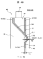
- FIG. 4A is a diagram showing an outline of a seal structure portion in the three-way junction portion 50J according to the first embodiment of the present invention, and is a plan view of the seal structure portion viewed from above.
- FIG. 4B is a cross-sectional view showing an outline of the IVB-IVB cross section of FIG. 4A.
- FIG. 4C is a cross-sectional view showing an outline of the IVC-IVC cross section of FIG. 4A.
- the same components as those in the above-described embodiment are designated by the same reference numerals as those in the above-described embodiment, and duplicate description will be omitted.
- a configuration different from the above-described embodiment will be described.
- the bottom surface of the seal groove 41 of the base 40 is recessed downward with respect to the bottom surface portion of the other seal groove 41 portion in the three-way junction 50J. It has a concave-shaped portion (first concave-shaped portion) 41JA1.
- the first concave shape portion 41JA1 constitutes a space portion (first space portion) further recessed from the surface forming the seal groove (recess portion) 41, and is a groove expansion portion (first groove) that expands the internal space of the seal groove 41. (Expansion part) is configured.
- the first concave shape portion 41JA1 expands the seal groove 41 in the depth direction (height direction).
- the first concave shape portion 41JA1 is formed on the bottom surface of the seal grooves 413 and 414, and is located on the extension line of the seal grooves 222 and 223.
- the seal expansion portion (first seal expansion portion) 50JA1 is formed.
- the seal groove (recessed portion) 41 is formed in the base 40 so as to be recessed in the thickness direction (height direction H) of the base 40.
- the first concave shape portion (space portion) 41JA1 is formed in the base 40 so as to be recessed deeper than the recess portion 41 in the thickness direction of the base 40.
- the first concave shape portion (space portion) 41JA1 may be formed only on the inner portion of the recessed portion 41 of the base 40 so as to be recessed deeper than the recessed portion 41 in the thickness direction of the base 40.
- the first concave-shaped portion 41JA1 serves as a relief portion for the excess sealing agent, and the excess sealing agent is absorbed by the first concave-shaped portion 41JA1. As a result, the protrusion of the sealant 50 to the outside of the electronic control device 1 is suppressed.
- the amount of the sealant 50 applied in the seal groove 41 can be increased in the three-way junction 50J. If the connector 21 is twisted when the other connector is inserted into or removed from the connector 21, the highest stress is generated at the three-way junction 50J. By increasing the amount of the sealing material 50 applied to the three-way junction 50J, the stress generated at the three-way junction 50J can be reduced.
- a convex portion 352 to be inserted into the first concave shape portion 41JA1 is provided at the lower end portions 35 of the side walls 32 and 34 of the cover 30.
- the convex shape portion T2 formed between the bottom surface of the seal groove 41 and the tip end (lower end) of the convex shape portion 352 is larger than the seal thickness T1 of the other portion.
- the electronic control device 1 is configured as follows.
- the seal groove (recessed portion) 41 is formed in the base 40 so as to be recessed in the thickness direction of the base 40.
- the first concave-shaped portion (space portion) 41JA1 is formed in the base 40 so as to be recessed deeper than the recessed portion 41 in the thickness direction of the base 40.
- the cover 30 has cover bodies 31, 32, 33, 34 that cover the electronic circuit board 60, and an insertion portion 35 that is inserted into the recessed portion 41.
- the insertion portion 35 has a convex portion 352 that is inserted into the space portion 41JA1.
- the convex portion 352 is not provided, and the lower end portions 35 of the side walls 32 and 34 of the cover 30 may be formed in a straight line as shown by the dotted line IL1.
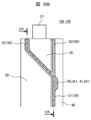
- FIG. 5A is a diagram showing an outline of a seal structure portion in the three-way junction portion 50J according to the second embodiment of the present invention, and is a plan view of the seal structure portion viewed from above.
- FIG. 5B is a cross-sectional view showing an outline of the VB-VB cross section of FIG. 5A.
- FIG. 5C is a cross-sectional view showing an outline of the VC-VC cross section of FIG. 5A.
- the same components as those in the above-described embodiment are designated by the same reference numerals as those in the above-described embodiment, and duplicate description will be omitted.
- a configuration different from the above-described embodiment will be described.
- the inner side wall (inner side surface) of the seal groove 41 is recessed in the three-way junction 50J in the horizontal direction (lateral direction) toward the inside of the electronic control device 1. It has a concave-shaped portion (second concave-shaped portion) 41JA2.
- the second concave shape portion 41JA2 constitutes a space portion (second space portion) further recessed from the surface forming the seal groove (recess portion) 41, and expands the seal groove 41 in the groove width direction (horizontal direction). A part (second groove expansion part) is formed. Further, the second concave shape portion 41JA2 constitutes a widening portion that widens the seal groove 41 in the groove width direction.
- the bottom surface of the second concave shape portion 41JA2 is configured to have the same depth as the bottom surface portion of the other seal groove 41 portion.
- the second concave shape portion 41JA2 is formed on the inner side surface of the seal grooves 413 and 414, and is located on the side of the intersection position where the extension lines of the seal grooves 222 and 223 intersect the seal grooves 41 (413,414).
- the seal groove (recessed portion) 41 is formed in the base 40 so as to be recessed in the thickness direction of the base 40.
- the second concave-shaped portion (space portion) 41JA2 is formed in the base 40 so as to be recessed from the inner side surface of the recessed portion 41 toward the inside of the base 40.
- the second concave-shaped portion 41JA2 serves as a relief portion for the excess sealing agent, and the excess sealing agent is also absorbed by the second concave-shaped portion 41JA2. In this case, the volume of the relief portion of the excess sealant can be increased.
- the seal expansion portion (second seal expansion portion) 50JA2 is formed.
- the second concave shape portion 41JA2 is provided together with the first concave shape portion 41JA1 of the first embodiment, but the structure may not include the first concave shape portion 41JA1.
- the second concave-shaped portion 41JA2 can form a relief portion for the excess sealant. Further, by making the bottom surface of the second concave shape portion 41JA2 the same depth as the bottom surface portion of the other seal groove 41 portion, the space in the height direction of the electronic control device 1 is not required, and the height of the electronic control device 1 is increased. The dimension (thickness) in the vertical direction can be reduced.
- the bottom surface of the second concave shape portion 41JA2 is configured to have the same depth as the bottom surface of the first concave shape portion 41JA1, and the volume of the relief portion of the excess sealant is large. It may be configured to be larger.
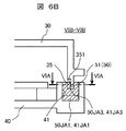
- FIG. 6A is a diagram showing an outline of a seal structure portion in the three-way junction portion 50J according to the third embodiment of the present invention, and is a cross-sectional view of the seal structure portion (VIA-VIA cross-sectional view of FIG. 6B).
- FIG. 6B is a cross-sectional view showing an outline of the VIB-VIB cross section of FIG. 6A.
- the same components as those in the above-described embodiment are designated by the same reference numerals as those in the above-described embodiment, and duplicate description will be omitted.
- a configuration different from the above-described embodiment will be described.
- the lower end portion (lower edge portion) 35 of the side walls 32 and 34 of the cover 30 inserted into the seal groove 41 at the three-way junction 50J has a third concave portion having a structure in which the thickness thereof is partially reduced. It has a shape portion 41JA3.
- the third concave shape portion 41JA3 constitutes a groove expansion portion (third groove expansion portion) that expands the seal groove 41 in the groove width direction (lateral direction). That is, the third concave-shaped portion 41JA3 is composed of a thin-walled portion 351 formed at the lower end portions 35 of the side walls 32 and 34 of the cover 30 at the three-way junction portion 50J.
- the thin-walled portion 351 expands the space in the seal groove 41.
- the third concave-shaped portion 41JA3 is provided in addition to the first concave-shaped portion 41JA1 of the first embodiment.
- the third concave-shaped portion 41JA3 serves as a relief portion for the excess sealing agent together with the first concave-shaped portion 41JA1, and the excess sealing agent is also absorbed by the third concave-shaped portion 41JA3. In this case, the volume of the relief portion of the excess sealant can be increased.
- the seal expansion portion (third seal expansion portion) 50JA3 is formed.
- the excess sealant can be absorbed without widening the width of the seal groove 41, and the width dimension of the electronic control device 1 can be reduced.
- the third concave shape portion 41JA3 of this embodiment is provided together with the first concave shape portion 41JA1 of the first embodiment, but may have a structure without the first concave shape portion 41JA1. In this case as well, the third concave-shaped portion 41JA3 can form a relief portion for the excess sealant.
- the third concave shape portion 41JA3 of the present embodiment may be configured together with the second concave shape portion 41JA2 of the second embodiment.
- the third concave shape portion 41JA3, the second concave shape portion 41JA2, and the first concave shape portion 41JA1 may all be provided.
- the depth of the seal groove 41 in the first concave shape portion 41JA1 and the second concave shape portion 41JA2 in this case the configurations described in the above-described first and second embodiments can be appropriately adopted.
- FIG. 7A is a diagram showing an outline of a seal structure portion in the three-way junction portion 50J according to the fourth embodiment of the present invention, and is a cross-sectional view of the seal structure portion (VIIA-VIIA sectional view of FIG. 7B).
- FIG. 7B is a cross-sectional view showing an outline of the VIIB-VIIB cross section of FIG. 7A.
- the same components as those in the above-described embodiment are designated by the same reference numerals as those in the above-described embodiment, and duplicate description will be omitted.
- a configuration different from the above-described embodiment will be described.
- the first concave-shaped portion 41JA1 of the first embodiment is placed inside the electronic control device 1 in the seal groove 41 from directly below the lower end portion (seal structure portion) 35 of the side walls 32 and 34 of the cover 30. It has a structure that is arranged at a position shifted toward it.
- the seal expansion portion 50JA1 is formed by the sealing agent 50 entering the first concave shape portion 41JA1.
- the sealant 50 when the sealant 50 is applied to the seal groove 41 and the cover 30 is assembled, the sealant 50 may be crushed by the lower ends 35 of the side walls 32 and 34 of the cover 30 and the bottom surface of the seal groove 41. can. That is, as compared with the case where the first concave shape portion 41JA1 is formed on the entire groove width of the seal groove 41 as in the first embodiment, the lower end portions 35 of the side walls 32 and 34 of the cover 30 and the bottom surface of the seal groove 41 The interval between the two is narrowed, and the effect of crushing the sealant 50 by the lower end portions 35 of the side walls 32 and 34 is improved. Thereby, in this embodiment, the filling property of the sealant 50 into the seal groove 41 is improved.
- FIG. 8 is a perspective view showing an appearance according to a modified example of the electronic control device 1 of FIG.
- the same components as those in the above-described embodiment are designated by the same reference numerals as those in the above-described embodiment, and duplicate description will be omitted.
- a configuration different from the above-described embodiment will be described.
- the electronic control device 1 of this embodiment has mounting brackets 42 to the vehicle and fixing portions 70 of the cover 30 on both side surfaces.
- the electronic control device 1 has a mounting bracket 42 for a vehicle in the vicinity of a portion (three-way junction portion) 50J where the first seal portion 51, the second seal portion 52, and the third seal portion 53 intersect. Further, the electronic control device 1 has a fixing portion 70 for fixing the cover 30 to the base 40 in the vicinity of the portion (three-way junction portion) 50J where the first seal portion 51, the second seal portion 52, and the third seal portion intersect. ..
- the protruding sealant 50 adheres to the mounting bracket 42 and the fixing portion 70 of the cover 30.
- the sealing agent that has squeezed out from the fixing tool when the electronic control device 1 is attached to the vehicle interferes with the fixing tool, or the fixing portion 70 cannot be fixed well.
- the first concave shape portion 41JA1, the second concave shape portion 41JA2, and the third concave shape portion 41JA3 have been described as being provided in both of the two three-way junction portions 50J, but at least one of them. It may be applied to one of the three-way junctions 50J.
- the electronic control device 1 has either the following configuration (1) or (2).
- a base member 40 having a recessed portion (seal groove) 41 on the outer periphery and a storage space for the electronic circuit board 60 formed inside the recessed portion 41.
- a cover member 30 that covers the electronic circuit board 60 and is attached to the base member 40,
- an electronic control device having a connector 21 and a connector housing 20 in which at least a part is housed between a base member 40 and a cover member 30.
- a space portion that is connected to the recess portion 41 and further recessed from the surface forming the recess portion 41 is formed. ..
- the space portion is composed of at least one of the first concave shape portion 41JA1 and the second concave shape portion 41JA2.
- a base member 40 having a recessed portion (seal groove) 41 on the outer periphery and a storage space for the electronic circuit board 60 formed inside the recessed portion 41.
- a cover member 30 that covers the electronic circuit board 60 and is attached to the base member 40, In an electronic control device having a connector 21 and a connector housing 20 in which at least a part is housed between a base member 40 and a cover member 30.
- a first seal portion 51 provided in the recess portion 41 and sealing between the base member 40 and the cover member 30 and A second seal portion 52 provided in the recess portion 41 and sealing between the base member 40 and the connector housing 20 and A third seal portion 53 that connects to the first seal portion 51 and the second seal portion 52 and seals between the cover member 30 and the connector housing 20 is provided.
- the recessed portion 41 is formed in the base member 40 so as to be recessed in the thickness direction of the base member 40.
- the cover member 30 has cover bodies 31, 32, 33, 34 that cover the electronic circuit board 60, and an insertion portion 35 that is inserted into the recessed portion 41.
- the thickness of the insertion portion 35 is formed to be thin, or the recess portion 41 is formed to be low in the depth direction, or is recessed.
- Expansion portions (space portions) 41JA1, 41JA2, 41JA3 are formed by denting from the inner side surface of the portion 41 toward the inside of the base member 40, thereby expanding the internal space of the recessed portion 41.
- At least one place where the space portions 41JA1 and 41JA2 which are further recessed from the surface forming the recessed portion 41 is formed is provided. Further, at least one place where the expansion portions 41JA1, 41JA2 and 41JA3 are formed is provided.
- the space portions 41JA1, 41JA2, and 41JA3 form a surplus sealant accommodating portion for accommodating a surplus of the sealant 50 filled in the recess 41. Further, a space portion 41JA1 and 41JA2 that are further recessed from the surface forming the seal groove (recessed portion) 41 and a space portion (expansion portion) 41JA3 that expands the internal space of the seal groove (recessed portion) 41 are formed. At least one place is provided.
- the first concave shape portion 41JA1, the second concave shape portion 41JA2, and the third concave shape portion 41JA3 are provided to form a relief portion for the excess sealant. Therefore, the first concave shape portion 41JA1, the second concave shape portion 41JA2, and the third concave shape portion 41JA3 are formed at a portion (three-way junction portion) 50J where the first seal portion 51, the second seal portion 52, and the third seal portion 53 intersect. Placed in the vicinity. In this case, the “neighborhood” means that the liquid excess sealant is within a range in which the liquid excess sealant can flow into the concave portions 41JA1, 41JA2, and 41JA3.
- the present invention is not limited to each of the above-described embodiments, and includes various modifications.
- the above-described embodiment has been described in detail in order to explain the present invention in an easy-to-understand manner, and is not necessarily limited to the one including all the configurations.
- it is possible to replace a part of the configuration of one embodiment with the configuration of another embodiment and it is also possible to add the configuration of another embodiment to the configuration of one embodiment.
Landscapes
- Engineering & Computer Science (AREA)
- Microelectronics & Electronic Packaging (AREA)
- Mechanical Engineering (AREA)
- Casings For Electric Apparatus (AREA)
Priority Applications (4)
| Application Number | Priority Date | Filing Date | Title |
|---|---|---|---|
| DE112021000956.7T DE112021000956T5 (de) | 2020-04-21 | 2021-02-02 | Elektronische steuereinheit |
| JP2022516850A JP7449372B2 (ja) | 2020-04-21 | 2021-02-02 | 電子制御装置 |
| CN202180027548.3A CN115380635B (zh) | 2020-04-21 | 2021-02-02 | 电子控制装置 |
| US17/919,452 US12464668B2 (en) | 2020-04-21 | 2021-02-02 | Electrical control unit with sealant between a cover, a base, and an electrical connector |
Applications Claiming Priority (2)
| Application Number | Priority Date | Filing Date | Title |
|---|---|---|---|
| JP2020-075425 | 2020-04-21 | ||
| JP2020075425 | 2020-04-21 |
Publications (1)
| Publication Number | Publication Date |
|---|---|
| WO2021215067A1 true WO2021215067A1 (ja) | 2021-10-28 |
Family
ID=78270451
Family Applications (1)
| Application Number | Title | Priority Date | Filing Date |
|---|---|---|---|
| PCT/JP2021/003646 Ceased WO2021215067A1 (ja) | 2020-04-21 | 2021-02-02 | 電子制御装置 |
Country Status (5)
| Country | Link |
|---|---|
| US (1) | US12464668B2 (https=) |
| JP (1) | JP7449372B2 (https=) |
| CN (1) | CN115380635B (https=) |
| DE (1) | DE112021000956T5 (https=) |
| WO (1) | WO2021215067A1 (https=) |
Citations (5)
| Publication number | Priority date | Publication date | Assignee | Title |
|---|---|---|---|---|
| JP2009123558A (ja) * | 2007-11-15 | 2009-06-04 | Denso Corp | 電子制御装置 |
| JP2013168674A (ja) * | 2013-05-01 | 2013-08-29 | Mitsubishi Electric Corp | 電子制御装置 |
| WO2016031511A1 (ja) * | 2014-08-29 | 2016-03-03 | 日立オートモティブシステムズ株式会社 | 電子制御装置 |
| JP2016143852A (ja) * | 2015-02-05 | 2016-08-08 | 株式会社デンソー | 電子装置 |
| JP2017004698A (ja) * | 2015-06-08 | 2017-01-05 | 株式会社デンソー | 電子装置 |
Family Cites Families (5)
| Publication number | Priority date | Publication date | Assignee | Title |
|---|---|---|---|---|
| JPS6426885U (https=) | 1987-08-08 | 1989-02-15 | ||
| JP4483960B2 (ja) | 2008-03-19 | 2010-06-16 | 株式会社デンソー | 電子装置 |
| JP2013105766A (ja) | 2011-11-10 | 2013-05-30 | Mitsubishi Electric Corp | 電子制御装置 |
| JP6044312B2 (ja) * | 2012-12-11 | 2016-12-14 | アイシン・エィ・ダブリュ株式会社 | 電子回路装置 |
| JP6022013B1 (ja) | 2015-10-16 | 2016-11-09 | 三菱電機株式会社 | 防水型制御ユニットとその組立方法 |
-
2021
- 2021-02-02 US US17/919,452 patent/US12464668B2/en active Active
- 2021-02-02 WO PCT/JP2021/003646 patent/WO2021215067A1/ja not_active Ceased
- 2021-02-02 JP JP2022516850A patent/JP7449372B2/ja active Active
- 2021-02-02 DE DE112021000956.7T patent/DE112021000956T5/de active Pending
- 2021-02-02 CN CN202180027548.3A patent/CN115380635B/zh active Active
Patent Citations (5)
| Publication number | Priority date | Publication date | Assignee | Title |
|---|---|---|---|---|
| JP2009123558A (ja) * | 2007-11-15 | 2009-06-04 | Denso Corp | 電子制御装置 |
| JP2013168674A (ja) * | 2013-05-01 | 2013-08-29 | Mitsubishi Electric Corp | 電子制御装置 |
| WO2016031511A1 (ja) * | 2014-08-29 | 2016-03-03 | 日立オートモティブシステムズ株式会社 | 電子制御装置 |
| JP2016143852A (ja) * | 2015-02-05 | 2016-08-08 | 株式会社デンソー | 電子装置 |
| JP2017004698A (ja) * | 2015-06-08 | 2017-01-05 | 株式会社デンソー | 電子装置 |
Also Published As
| Publication number | Publication date |
|---|---|
| JP7449372B2 (ja) | 2024-03-13 |
| DE112021000956T5 (de) | 2022-11-24 |
| JPWO2021215067A1 (https=) | 2021-10-28 |
| CN115380635A (zh) | 2022-11-22 |
| US20230156948A1 (en) | 2023-05-18 |
| US12464668B2 (en) | 2025-11-04 |
| CN115380635B (zh) | 2026-01-13 |
Similar Documents
| Publication | Publication Date | Title |
|---|---|---|
| JP4867280B2 (ja) | コーティング剤塗布方法 | |
| US8107251B2 (en) | Electronic device | |
| TWI806001B (zh) | 連接器及連接器組件 | |
| JP5499125B2 (ja) | 筐体及びその筐体の組立方法 | |
| CN104203652A (zh) | 车辆的电子控制装置 | |
| US9093776B2 (en) | Electronic control device | |
| JP6391829B2 (ja) | 防水型電子制御装置 | |
| JP4377919B2 (ja) | 電気接続箱 | |
| EP0557883A1 (en) | Laminated electronic module assembly | |
| CN115988810A (zh) | 电子装置 | |
| CN107732553B (zh) | 电连接器及其制造方法 | |
| WO2021215067A1 (ja) | 電子制御装置 | |
| JP2019139835A (ja) | 電気コネクタ | |
| US11147173B2 (en) | Electronic device | |
| JP2016162663A (ja) | 電子制御装置 | |
| JP6887918B2 (ja) | 電気接続箱 | |
| JP2003309379A (ja) | 基板装着筐体の構造及び基板実装構造 | |
| WO2022249558A1 (ja) | 自動車用制御装置 | |
| JP7601651B2 (ja) | コネクタ | |
| JP7585992B2 (ja) | 電子装置 | |
| JP2020205154A (ja) | 防水コネクタ | |
| JP7081672B2 (ja) | ノイズフィルタ | |
| WO2023199569A1 (ja) | 電動モータの駆動制御装置 | |
| JP2004039377A (ja) | 電子部品の端子接続部分への防湿剤塗布構造 | |
| JP3331902B2 (ja) | 電子部品 |
Legal Events
| Date | Code | Title | Description |
|---|---|---|---|
| 121 | Ep: the epo has been informed by wipo that ep was designated in this application |
Ref document number: 21792014 Country of ref document: EP Kind code of ref document: A1 |
|
| ENP | Entry into the national phase |
Ref document number: 2022516850 Country of ref document: JP Kind code of ref document: A |
|
| 122 | Ep: pct application non-entry in european phase |
Ref document number: 21792014 Country of ref document: EP Kind code of ref document: A1 |
|
| WWG | Wipo information: grant in national office |
Ref document number: 17919452 Country of ref document: US |