WO2021215052A1 - 尿道カテーテル用キャップ - Google Patents
尿道カテーテル用キャップ Download PDFInfo
- Publication number
- WO2021215052A1 WO2021215052A1 PCT/JP2020/048769 JP2020048769W WO2021215052A1 WO 2021215052 A1 WO2021215052 A1 WO 2021215052A1 JP 2020048769 W JP2020048769 W JP 2020048769W WO 2021215052 A1 WO2021215052 A1 WO 2021215052A1
- Authority
- WO
- WIPO (PCT)
- Prior art keywords
- cap
- urine
- lid
- urethral catheter
- hydrophobic film
- Prior art date
- Legal status (The legal status is an assumption and is not a legal conclusion. Google has not performed a legal analysis and makes no representation as to the accuracy of the status listed.)
- Ceased
Links
Images
























Classifications
-
- A—HUMAN NECESSITIES
- A61—MEDICAL OR VETERINARY SCIENCE; HYGIENE
- A61M—DEVICES FOR INTRODUCING MEDIA INTO, OR ONTO, THE BODY; DEVICES FOR TRANSDUCING BODY MEDIA OR FOR TAKING MEDIA FROM THE BODY; DEVICES FOR PRODUCING OR ENDING SLEEP OR STUPOR
- A61M39/00—Tubes, tube connectors, tube couplings, valves, access sites or the like, specially adapted for medical use
- A61M39/20—Closure caps or plugs for connectors or open ends of tubes
-
- A—HUMAN NECESSITIES
- A61—MEDICAL OR VETERINARY SCIENCE; HYGIENE
- A61M—DEVICES FOR INTRODUCING MEDIA INTO, OR ONTO, THE BODY; DEVICES FOR TRANSDUCING BODY MEDIA OR FOR TAKING MEDIA FROM THE BODY; DEVICES FOR PRODUCING OR ENDING SLEEP OR STUPOR
- A61M25/00—Catheters; Hollow probes
- A61M25/0017—Catheters; Hollow probes specially adapted for long-term hygiene care, e.g. urethral or indwelling catheters to prevent infections
-
- A—HUMAN NECESSITIES
- A61—MEDICAL OR VETERINARY SCIENCE; HYGIENE
- A61M—DEVICES FOR INTRODUCING MEDIA INTO, OR ONTO, THE BODY; DEVICES FOR TRANSDUCING BODY MEDIA OR FOR TAKING MEDIA FROM THE BODY; DEVICES FOR PRODUCING OR ENDING SLEEP OR STUPOR
- A61M25/00—Catheters; Hollow probes
- A61M25/0097—Catheters; Hollow probes characterised by the hub
-
- A—HUMAN NECESSITIES
- A61—MEDICAL OR VETERINARY SCIENCE; HYGIENE
- A61M—DEVICES FOR INTRODUCING MEDIA INTO, OR ONTO, THE BODY; DEVICES FOR TRANSDUCING BODY MEDIA OR FOR TAKING MEDIA FROM THE BODY; DEVICES FOR PRODUCING OR ENDING SLEEP OR STUPOR
- A61M27/00—Drainage appliance for wounds or the like, i.e. wound drains, implanted drains
-
- A—HUMAN NECESSITIES
- A61—MEDICAL OR VETERINARY SCIENCE; HYGIENE
- A61M—DEVICES FOR INTRODUCING MEDIA INTO, OR ONTO, THE BODY; DEVICES FOR TRANSDUCING BODY MEDIA OR FOR TAKING MEDIA FROM THE BODY; DEVICES FOR PRODUCING OR ENDING SLEEP OR STUPOR
- A61M39/00—Tubes, tube connectors, tube couplings, valves, access sites or the like, specially adapted for medical use
- A61M39/10—Tube connectors; Tube couplings
-
- A—HUMAN NECESSITIES
- A61—MEDICAL OR VETERINARY SCIENCE; HYGIENE
- A61M—DEVICES FOR INTRODUCING MEDIA INTO, OR ONTO, THE BODY; DEVICES FOR TRANSDUCING BODY MEDIA OR FOR TAKING MEDIA FROM THE BODY; DEVICES FOR PRODUCING OR ENDING SLEEP OR STUPOR
- A61M25/00—Catheters; Hollow probes
- A61M2025/0018—Catheters; Hollow probes having a plug, e.g. an inflatable plug for closing catheter lumens
-
- A—HUMAN NECESSITIES
- A61—MEDICAL OR VETERINARY SCIENCE; HYGIENE
- A61M—DEVICES FOR INTRODUCING MEDIA INTO, OR ONTO, THE BODY; DEVICES FOR TRANSDUCING BODY MEDIA OR FOR TAKING MEDIA FROM THE BODY; DEVICES FOR PRODUCING OR ENDING SLEEP OR STUPOR
- A61M39/00—Tubes, tube connectors, tube couplings, valves, access sites or the like, specially adapted for medical use
- A61M39/20—Closure caps or plugs for connectors or open ends of tubes
- A61M2039/205—Closure caps or plugs for connectors or open ends of tubes comprising air venting means
-
- A—HUMAN NECESSITIES
- A61—MEDICAL OR VETERINARY SCIENCE; HYGIENE
- A61M—DEVICES FOR INTRODUCING MEDIA INTO, OR ONTO, THE BODY; DEVICES FOR TRANSDUCING BODY MEDIA OR FOR TAKING MEDIA FROM THE BODY; DEVICES FOR PRODUCING OR ENDING SLEEP OR STUPOR
- A61M2210/00—Anatomical parts of the body
- A61M2210/10—Trunk
- A61M2210/1078—Urinary tract
-
- A—HUMAN NECESSITIES
- A61—MEDICAL OR VETERINARY SCIENCE; HYGIENE
- A61M—DEVICES FOR INTRODUCING MEDIA INTO, OR ONTO, THE BODY; DEVICES FOR TRANSDUCING BODY MEDIA OR FOR TAKING MEDIA FROM THE BODY; DEVICES FOR PRODUCING OR ENDING SLEEP OR STUPOR
- A61M2210/00—Anatomical parts of the body
- A61M2210/10—Trunk
- A61M2210/1078—Urinary tract
- A61M2210/1085—Bladder
-
- A—HUMAN NECESSITIES
- A61—MEDICAL OR VETERINARY SCIENCE; HYGIENE
- A61M—DEVICES FOR INTRODUCING MEDIA INTO, OR ONTO, THE BODY; DEVICES FOR TRANSDUCING BODY MEDIA OR FOR TAKING MEDIA FROM THE BODY; DEVICES FOR PRODUCING OR ENDING SLEEP OR STUPOR
- A61M2210/00—Anatomical parts of the body
- A61M2210/10—Trunk
- A61M2210/1078—Urinary tract
- A61M2210/1089—Urethra
Definitions
- the present invention relates to a cap for a urethral catheter.
- Patent Document 1 discloses a urethral catheter including a rod-shaped catheter body, a balloon portion formed at one end of the catheter body, and an operation portion formed at the other end of the catheter body.
- Patent Document 2 describes an end nozzle in which the lower end of the cylinder is formed in a spherical shape, and a notch and a lumen for slidably accommodating the lower end.
- a cap for a self-catheterization catheter comprising a housing provided with a lumen and a tubular base connector.
- a catheter cap as in Patent Document 2 is useful for controlling the overflow of urine from the catheter, but has some problems.
- indwelling catheter urinary catheterization using a catheter as in Patent Document 1 positioning of the indwelling balloon is important.
- a catheter is inserted into the urethra, it is confirmed that the catheter has reached the inside of the bladder and urine has begun to come out, and when the catheter is further inserted, the balloon is inflated to determine the position.
- the reason why the balloon is not inflated when it is confirmed that urine has begun to come out is that the balloon may be located in the urethra even if the tip of the catheter reaches the bladder, and then the balloon is inflated. This is because there is a risk of damaging the urethra.
- one object of the present invention is to provide a cap for a urethral catheter that can improve the workability of the catheter during self-catheterization.
- Another object of the present invention is to provide a cap for a urethral catheter that can prevent the urine discharged from the catheter from scattering during clean intermittent catheterization (CIC).
- CIC clean intermittent catheterization
- Yet another object of the present invention is to provide a cap for a urethral catheter that can appropriately determine the position of the balloon of the catheter when guiding the indwelling catheter.
- the cap for a urethral catheter includes a main body including a connection hole connected to the urethral catheter and a urine introduction path including a drain hole for draining urine, and a lid portion for opening and closing the drain hole. Includes an opening formed in the main body or the lid portion facing the urine introduction path, and a hydrophobic film formed so as to close the opening.
- a hydrophobic film is formed in the opening of the cap.
- the air inside the catheter can be released to the outside when the urethral catheter is inserted into the urethra, so that the urine in the bladder can be smoothly guided to the cap after the tip of the catheter reaches the bladder. ..
- the urine discharged from the bladder is blocked by the hydrophobic film, so that the urine can be retained by the urine introduction path of the cap. As a result, after confirming that the urine has reached the cap, the next work can be performed slowly without rushing.
- a urethral catheter is placed in a case containing a disinfectant solution to disinfect it.
- the disinfectant solution can be distributed inside the catheter even while attached to the urethral catheter. Can be done. As a result, the urethral catheter can be kept clean.
- the opening may be formed in the lid portion.
- the lid portion is openably and closably connected to the main body via a hinge mechanism, and the lid portion is inserted into the discharge hole. It may have a tubular plug portion in which the opening is formed.
- the lid portion is connected to the main body via a hinge mechanism, it is not necessary to position the lid portion with respect to the discharge hole when closing the lid portion. Further, since the portion that closes the discharge hole is the plug portion, the discharge hole can be easily closed by pushing the lid portion against the discharge hole.
- the lid portion may include a screw type lid portion that is removable with respect to the main body.
- the main body and the lid are screwed by the screw type lid, so that the discharge hole can be reliably closed.
- the opening may be formed so as to be connected to the middle portion of the urine introduction path of the main body in the urine flow direction.
- the hydrophobic film may be arranged in the film arrangement portion.
- the lid includes a Duckbill valve having a pair of tilted valves extending from the end of the discharge hole toward the connection hole so as to converge. May be good.
- a urine collection bag or the like can be directly inserted into the cap.
- the lid portion includes a plug portion inserted into the discharge hole and a stick-shaped lid portion having a columnar portion connected to the plug portion. May be good.
- the lid since the lid is stick-shaped, the lid can be easily opened with one hand by pressing the side surface of the lid with the thumb, for example.
- the film arrangement portion is formed in a flange shape with respect to the support protruding from the side wall of the main body and the support, and first engages with the peripheral edge portion.
- the lid portion includes a film arranging plate having a portion and on which the hydrophobic film is arranged, and the lid portion engages with the first engaging portion of the film arranging plate from the outer surface side of the film arranging plate.
- the second engaging portion may be included.
- the engagement between the first engaging portion and the second engaging portion can be released, and the lid portion can be opened. Since the lid can be opened without directly touching it, it is possible to reliably prevent urine from adhering to the hand when opening the lid.
- the main body may be made of a material containing a substance having an antibacterial action.
- the main body is made of a material containing a substance having an antibacterial action, so that the cap can be kept clean. Further, if a substance having an antibacterial action is contained, the amount of ammonia produced from urea when urine reaches the cap can be reduced, so that the odor of urine can be alleviated.
- the discharge hole may have a curved shape whose diameter increases as it approaches the opening end of the discharge hole.
- the main body may be formed of a translucent material containing a substance having a function of developing a color by the action of water.
- the color of the main body changes when urine reaches the cap, so the arrival of urine can be easily confirmed visually.
- the inner surface of the urine introduction path of the main body may be textured.
- the cap for a urethral catheter includes a detection means for detecting that urine has reached the urine introduction path and a transmission means for transmitting urine arrival information based on the detection of the detection means. May further be included.
- various information can be obtained depending on the type of transmission means.
- the transmitting means is a sounding means
- the arrival of urine can be easily confirmed by hearing
- the transmitting means is a vibrating means
- the arrival of urine can be easily confirmed by skin sensation.
- the transmitting means is a wireless transmitting means
- the medical staff or the patient himself / herself can indirectly obtain objective information as to whether or not the catheter has been inserted correctly.
- the cap for a urethral catheter may be attached to the main body or the lid portion so as to be openable and closable, and may further include a second lid portion that airtightly covers the hydrophobic film.
- the second lid portion by closing the second lid portion, it is possible to prevent the odor of urine that has reached the cap from leaking to the outside through the hydrophobic film.
- the second lid portion can be opened and closed, by opening the second lid portion until the urine reaches the cap, the air flowing to the outside through the hydrophobic film is not blocked.
- the hydrophobic film may be formed of a material containing an ammonia-degrading enzyme.
- the hydrophobic film may contain an acidic agent.
- the cap for a urethral catheter includes a main body including a connection hole connected to the urethral catheter and a urine introduction path including a drain hole for draining urine, and a first end portion on the drain hole side.
- a lid portion that has a tubular portion having a second end portion on the opposite side thereof and opens and closes the discharge hole, and a partition portion that divides the tubular portion of the lid portion into a plurality of spaces. Includes at least two or more hydrophobic films formed to close the space at the second end of the lid.
- a hydrophobic film is formed on the lid.
- the air inside the catheter can be released to the outside when the urethral catheter is inserted into the urethra, so that the urine in the bladder can be smoothly guided to the cap after the tip of the catheter reaches the bladder. ..
- the urine discharged from the bladder is blocked by the hydrophobic film, so that the urine can be retained by the urine introduction path of the cap. As a result, after confirming that the urine has reached the cap, the next work can be performed slowly without rushing.
- the lid is divided into a plurality of spaces, and each space is closed with a hydrophobic film.
- the partition portion may include a partition plate erected between a plurality of locations on the inner peripheral surface of the tubular portion of the lid portion.
- the volume of each space can be secured relatively large. Therefore, even if the disinfectant solution flows into the space, the influence of the surface tension of the disinfectant solution in the space can be reduced. As a result, the disinfectant solution in the space can be eliminated at an early stage.
- the lid portion includes a covering member formed at the second end portion of the tubular portion of the lid portion so as to cover the hydrophobic film.
- the covering member may have a protrusion protruding outward from its side wall.
- the protrusion for opening and closing the lid can be separated from the opening / closing position of the lid on the cap. Therefore, it is possible to prevent the urine from coming into contact with the hand when the lid is opened and the urine is discharged.
- the protruding portion may include an annular flange portion formed over the entire outer circumference of the covering member.
- the covering member includes a top wall portion that covers the hydrophobic film and has an upper surface composed of a plain surface in which no holes are formed, and a side wall of the covering member. May be formed with a flow port for ensuring the flow of air inside and outside the covering member in the lateral direction along the upper surface of the top wall portion.
- the hydrophobic film has a thickness of 10 ⁇ m to 2 mm, and the air flow rate (garley value) measured in accordance with JIS P8117 (Garley method).
- the water pressure resistance may be 0.1 kPa or more, and the water pressure resistance measured in accordance with JIS L1092-B (high water pressure method) may be 0.1 kPa to 500 seconds / 100 mL.
- the water repellency, breathability, pressure resistance and long-term water repellency of the hydrophobic film can be maintained even if the cap is used for a long period of time.
- FIG. 1 is a perspective view of a catheter to which a cap according to the first embodiment of the present invention is attached.
- 2A and 2B are views for explaining the cross-sectional structure of the shaft of FIG.
- FIG. 3 is a perspective view of the cap according to the first embodiment of the present invention.
- FIG. 4 is a perspective view of the cap according to the first embodiment of the present invention.
- FIG. 5 is a side view of the cap according to the first embodiment of the present invention.
- FIG. 6 is a diagram showing a cross section taken along the line AA of FIG.
- FIG. 7 is a cross-sectional view of the cap according to the second embodiment of the present invention.
- FIG. 8 is a cross-sectional view of the cap according to the second embodiment of the present invention.
- FIG. 1 is a perspective view of a catheter to which a cap according to the first embodiment of the present invention is attached.
- 2A and 2B are views for explaining the cross-sectional structure of the shaft of FIG.
- FIG. 9 is a perspective view of the cap according to the third embodiment of the present invention.
- FIG. 10 is a perspective view of the cap according to the fourth embodiment of the present invention.
- FIG. 11 is a bottom view of the lid portion of FIG.
- FIG. 12 is a side view of the main body of FIG.
- FIG. 13 is a diagram showing a cross section taken along the line AA of FIG.
- FIG. 14 is a perspective view of the cap according to the fifth embodiment of the present invention.
- FIG. 15 is a side view of the cap according to the fifth embodiment of the present invention.
- FIG. 16 is a diagram showing a cross section taken along the line AA of FIG.
- FIG. 17 is a perspective view of the cap according to the sixth embodiment of the present invention.
- FIG. 18 is a side view of the cap according to the sixth embodiment of the present invention.
- FIG. 19 is a diagram showing a cross section taken along the line AA of FIG.
- FIG. 20 is a perspective view of the cap according to the seventh embodiment of the present invention.
- FIG. 21 is a plan view of the cap according to the seventh embodiment of the present invention.
- FIG. 22 is a side view of the cap according to the seventh embodiment of the present invention.
- FIG. 23 is a rear view of the cap according to the seventh embodiment of the present invention.
- FIG. 24 is a diagram showing a cross section taken along the line AA of FIG.
- FIG. 25 is a diagram showing a BB cross section of FIG.
- FIG. 26 is a perspective view of the cap according to the eighth embodiment of the present invention.
- FIG. 24 is a diagram showing a cross section taken along the line AA of FIG.
- FIG. 25 is a diagram showing a BB cross section of FIG.
- FIG. 26 is a perspective view of
- FIG. 27 is a side view of the cap according to the eighth embodiment of the present invention.
- FIG. 28 is a diagram showing a cross section taken along the line AA of FIG.
- FIG. 29 is a diagram showing a cross section taken along the line AA of FIG. 26.
- FIG. 30 is a perspective view of the cap according to the ninth embodiment of the present invention.
- FIG. 31 is a side view of the cap according to the ninth embodiment of the present invention.
- FIG. 32 is a diagram showing a cross section taken along the line AA of FIG.
- FIG. 33 is a diagram showing a cross section taken along the line AA of FIG.
- FIG. 34 is a perspective view of the cap according to the tenth embodiment of the present invention.
- FIG. 35 is a side view of the cap according to the tenth embodiment of the present invention.
- FIG. 36 is a perspective view of the cap according to the tenth embodiment of the present invention.
- FIG. 37 is a side view of the cap according to the tenth embodiment of the present invention.
- FIG. 38A is a diagram for explaining a method of fixing the hydrophobic film.
- FIG. 38B is a diagram showing the next step of FIG. 38A.
- FIG. 39A is a diagram for explaining a method of fixing the hydrophobic film.
- FIG. 39B is a diagram showing the next step of FIG. 39A.
- FIG. 39C is a diagram showing the next step of FIG. 39B.
- FIG. 39D is a diagram showing the next step of FIG. 39C.
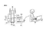
- FIG. 40 is a diagram for explaining how to use the catheter.
- FIG. 41 is a diagram for explaining how to use the catheter.
- FIG. 42 is a diagram for explaining how to use the catheter.
- FIG. 43 is a diagram showing a state of the catheter at the time of disinfection.
- FIG. 44 is a perspective view of the cap according to the eleventh embodiment of the present invention.
- FIG. 45 is a diagram showing a cross section taken along the line AA of FIG. 44.
- FIG. 46 is a perspective view of the cap of FIG. 45.
- FIG. 47 is a diagram for explaining the internal structure of the lid portion of the cap of FIG. 44.
- FIG. 48 is a diagram for explaining the effect of the cap of FIG. 44.
- FIG. 49 is a diagram for explaining the effect of the cap of FIG. 44.
- FIG. 50 is a perspective view of the cap according to the twelfth embodiment of the present invention.
- FIG. 51 is a diagram showing a cross section taken along the line AA of FIG.
- FIG. 52 is a perspective view of the cap of FIG. 51.
- FIG. 53 is a diagram for explaining the internal structure of the lid portion of the cap of FIG. 50.
- FIG. 54 is a perspective view of the cap according to the thirteenth embodiment of the present invention.
- FIG. 55 is a perspective view of the cap according to the thirteenth embodiment of the present invention.
- FIG. 56 is a plan view of the cap according to the thirteenth embodiment of the present invention.
- FIG. 57 is a side view of the cap according to the thirteenth embodiment of the present invention.
- FIG. 51 is a diagram showing a cross section taken along the line AA of FIG.
- FIG. 52 is a perspective view of the cap of FIG. 51.
- FIG. 53 is a diagram for explaining the internal structure of the lid portion of the cap of FIG.
- FIG. 58 is a diagram showing a cross section taken along the line AA of FIG. 56.
- FIG. 59 is an exploded view of the cap according to the thirteenth embodiment of the present invention.
- FIG. 60 is a diagram showing a first form of the covering member of the cap of FIG. 55.
- FIG. 61 is a cross-sectional view showing a cross section taken along the line AA of FIG. 60.
- FIG. 62 is a cross-sectional view showing a cross section taken along the line AA of FIG. 60.
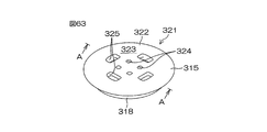
- FIG. 63 is a diagram showing a second form of the covering member of the cap of FIG. 55.
- FIG. 64 is a cross-sectional view showing a cross section taken along the line AA of FIG. 63.
- FIG. 65 is a cross-sectional view showing a cross section taken along the line AA of FIG. 63.
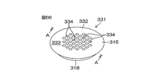
- FIG. 66 is a diagram showing a third form of the covering member of the cap of FIG. 55.
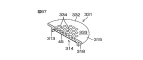
- FIG. 67 is a cross-sectional view showing a cross section taken along the line AA of FIG. 66.
- FIG. 68 is a cross-sectional view showing a cross section taken along the line AA of FIG.
- FIG. 69 is a diagram showing a modified example of the cap.
- FIG. 70 is a diagram showing an example of how to use the cap.
- FIG. 1 is a schematic perspective view of a catheter 1 to which a cap A1 according to the first embodiment of the present invention is attached.
- 2A and 2B are views for explaining the cross-sectional structure of the shaft 2 of FIG. Note that FIG. 1 shows a state in which the balloon 6 of the catheter 1 is not inflated.
- the catheter 1 is, for example, a medical device (urethral catheter) for assisting urination of a patient who has difficulty in urinating, and includes a shaft 2 and a base 3.
- a medical device urethral catheter
- the shaft 2 is made of, for example, a flexible tube, and a hard cap 4 is attached to the tip thereof.
- the shaft 2 is inserted into the cap 4 to form an inlay structure, and the mating surfaces of the inrow structure are fixed to each other by welding, adhering, or the like.
- the shaft 2 and the cap 4 may be made of, for example, a rubber latex base material such as natural rubber latex or synthetic rubber latex, a base member such as a silicone base material or a thermoplastic elastomer, which has been surface-treated.
- a rubber latex base material such as natural rubber latex or synthetic rubber latex
- a base member such as a silicone base material or a thermoplastic elastomer
- the surface treatment include a hydrophilic coating that imparts lubricity to the base member, a urethane coating / fluorine coating that imparts smoothness to the base member, and a silver coating that imparts antibacterial properties to the base member. Two or more of these surface treatments may be used in combination.
- a side hole 5 and a balloon 6 are formed at the tip of the shaft 2.
- a urinary catheterization lumen 7 and a balloon lumen 8 communicating with the side hole 5 and the balloon 6 are formed inside the shaft 2.
- the peripheral surface 9 of the shaft 2 may be a smooth surface as shown in FIG. 2A or an uneven surface as shown in FIG. 2B.
- the peripheral surface 9 of the shaft 2 is formed as an uneven surface by a plurality of ribs 10 (convex) extending in the longitudinal direction of the shaft 2. The rib 10 can reduce friction when inserting the catheter 1 into the urethra or pulling out the catheter 1 from the urethra, so that the patient's discomfort can be reduced.
- the balloon 6 may be integrally formed with the shaft 2.
- the connection portion may not be formed between the balloon 6 and the shaft 2 (note that in FIG. 1, the vague boundary 11 between the balloon 6 and the shaft 2 is shown by a broken line).
- the surface of the balloon 6 and the surface of the shaft 2 (peripheral surface 9) can be made continuous with a smooth surface.
- the friction when inserting the catheter 1 into the urethra or pulling out the catheter 1 from the urethra can be reduced, so that the discomfort of the patient can be reduced.
- the shaft 2 may be fitted with a cylindrical sleeve 12.
- the sleeve 12 is attached so as to be movable in the longitudinal direction of the shaft 2.
- the catheter 1 can be hygienically inserted by inserting the catheter 1 while grasping the shaft 2 through the sleeve 12.
- the base 3 may include a urination base 13 and a balloon base 14.
- the urination base 13 is an outlet from which urine guided from the side hole 5 to the urinary lumen 7 is discharged.
- the balloon base 14 is an injection port for sterilized water for inflating the balloon 6, and includes a check valve 15.
- the urination base 13 and the balloon base 14 are formed in a cylindrical shape in which a urine introduction path 16 and a water introduction path 17 are formed inside, respectively.
- the urination base 13 and the balloon base 14 are formed in a tubular shape having a substantially constant diameter, but for example, the urination base 13 and the balloon base 14 are outward toward the open ends of each. It may be formed in a funnel shape with a wide diameter.
- the urination base 13 and the balloon base 14 may be referred to as a urination funnel and a balloon funnel, respectively.
- the cap A1 for the urethral catheter according to the first embodiment of the present invention is provided at the open end of the urination base 13.
- the cap A1 is detachably attached to the urination base 13 by inserting the connection portion 23, which will be described later, into the urine introduction path 16 of the urination base 13.
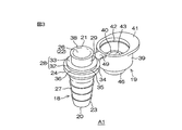
- FIG. 3 and 4 are perspective views of the cap A1 according to the first embodiment of the present invention, FIG. 3 shows a state in which the lid portion 19 is open, and FIG. 4 shows a state in which the lid portion 19 is closed.
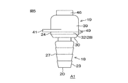
- FIG. 5 is a side view of the cap A1 according to the first embodiment of the present invention.
- FIG. 6 is a diagram showing a cross section taken along the line AA of FIG.
- the cap A1 may include a main body 18 and a lid portion 19.
- the main body 18 and the lid 19 are formed of an integral resin, and may be an integral resin molded product.
- the main body 18 and the lid 19 may be made of, for example, general-purpose plastic (for example, polypropylene, polyethylene, ABS resin, polycarbonate, polyamide, etc.). Further, these general-purpose plastics may have translucency.
- the main body 18 and the lid 19 can be manufactured as molded products by a known molding method such as injection molding, compression molding, or 3D printer molding.
- the main body 18 and the lid portion 19 may contain a substance having an antibacterial action, a substance having a function of developing a color by the action of water, and the like.
- a substance having an antibacterial action for example, a zeolite-based, silica gel-based, glass-based, phosphate-based or other antibacterial agent can be used.
- a substance having a function of developing a color by the action of water for example, Hydrochromic (registered trademark) manufactured by Pilot Ink Co., Ltd. can be used.
- a substance having an antibacterial action and a substance having a function of developing a color by the action of water are kneaded into the above-mentioned general-purpose plastic and mixed to form the mixture. do it.
- the cap A1 can be kept clean. Further, if a substance having an antibacterial action is contained, the amount of ammonia produced from urea when urine reaches the cap A1 can be reduced, so that the odor of urine can be alleviated. Further, if the main body 18 and the lid 19 contain a substance having a function of developing color by the action of water, the color of the main body 18 changes when urine reaches the cap A1, so that the arrival of urine can be easily visually performed. You can check.
- the main body 18 has a first end portion 20 and a second end portion 21, and is formed in a cylindrical shape in which a urine introduction path 22 extending from the first end portion 20 to the second end portion 21 is formed inside.
- the inner surface of the urine introduction path 22 may be textured.
- the embossing can be applied to the inner surface of the urine introduction path 22 by forming a pattern corresponding to the embossing on the surface of the molding die of the cap A1, for example. In this way, if the urine introduction path 22 is textured, the light reflection state of the main body 18 changes when the urine reaches the cap A1, so that the arrival of the urine can be easily confirmed visually. can.
- the main body 18 contains a substance having a function of developing color by the action of water and that the main body 18 is textured may be provided as both features of the cap A1, or only one of them. It may be provided.
- the main body 18 may include a connecting portion 23 and a discharging portion 24 as an external shape in this embodiment.
- the urine introduction path 22 may be divided into a connection hole 25 on the connection portion 23 side and a discharge hole 26 on the discharge portion 24 side.
- the connecting portion 23 is a portion connected to the urination base 13 of the catheter 1
- the discharging portion 24 is a portion other than the connecting portion 23, and is a portion where urine is finally discharged.
- the connection unit 23 and the discharge unit 24 do not have to have functional names, respectively.
- the connection unit 23 is referred to as the first part of the main body 18, and the discharge unit 24 is referred to as the second part of the main body 18. You may.
- the connecting portion 23 may be, for example, a tapered plug portion whose outer diameter narrows toward the first end portion 20 side of the main body 18.
- a plurality of (three in this embodiment) step portions 27 for preventing the connecting portion 23 from coming off with respect to the base portion 3 are provided in the axial direction of the connecting portion 23 (direction along the urine introduction path 22). ) Are formed at intervals from each other.
- Each step portion 27 is formed over the entire circumference of the connecting portion 23 in the circumferential direction.
- the discharge portion 24 may include a flange-shaped base portion 28 connected to the connection portion 23 and a discharge port 29 extending from the base portion 28 to the second end portion 21 side of the main body 18.
- the base portion 28 may have a first surface 30 on the connecting portion 23 side and a second surface 31 on the opposite side.
- the base portion 28 integrates an annular first portion 32 on the first surface 30 side and an annular second portion 33 formed on the second surface 31 side and having an outer diameter smaller than that of the first portion 32. May be included.
- a circular step portion 34 is formed between the first portion 32 and the second portion 33 over the entire circumference of the base portion 28 in the circumferential direction.
- the step portion 34 has a side surface 35 and a bottom surface 36, and is formed by the side surface of the second portion 33 and the upper surface of the first portion 32, respectively.
- a ridge 37 projecting laterally from the side surface 35 is formed in a circular shape over the entire circumference of the first portion 32 in the circumferential direction.
- the discharge port 29 is formed in a cylindrical shape.
- a curved portion 38 is formed at the open end of the discharge port 29 so that the outer diameter increases as it approaches the open end. That is, the outer peripheral surface of the discharge port 29 is a surface curved outward at the open end.
- the curved portion 38 improves the urine drainage at the edge of the discharge port 29 and suppresses the occurrence of urine dripping from the discharge port 29. As a result, it is possible to omit the work of wiping the edge of the discharge port 29 after the discharge of urine, and it is possible to prevent the cap A1 from being contaminated with urine after the discharge of urine from the discharge port 29.
- the base portion 28 has a two-stage structure of the first portion 32 and the second portion 33, the urine is collected from the upper surface of the second portion 33 (the second surface of the base portion 28). It can be stopped at 31). Then, as shown in FIG. 6, the upper surface of the second portion 33 is a portion covered by the lid portion 19 when the lid portion 19 is closed, so that it is possible to prevent the dripping urine from being exposed to the outside. can. Further, in the discharge port 29, the discharge hole 26 has a tapered shape in which the diameter narrows from the open end (second end 21 of the main body 18) toward the connection portion 23.
- the lid portion 19 may include a base portion 39 having a hollow dome shape inside, and a plug portion 40 projecting from the inner surface of the top of the base portion 39 to the inside of the base portion 39.
- the dome-shaped base portion 39 may include a top portion which is an upper end portion and a base portion which is a lower end portion.
- a flange portion 41 is formed on the base portion of the base portion 39 so as to project outward from the peripheral surface of the base portion 39.
- the flange portion 41 is selectively formed from a part of the base portion of the base portion 39.
- the base portion 39 is formed in a cap shape as a whole.
- a recess 42 is formed in a circular shape over the entire circumference of the base portion 39 in the circumferential direction.
- the dent 42 is formed with a width in which the above-mentioned ridge 37 can be fitted.
- the plug portion 40 is formed in a cylindrical shape in which an opening 43 is formed, and is formed shorter than the height of the base portion 39. Further, the plug portion 40 has a tapered shape in which the outer diameter narrows toward the tip of the plug portion 40.
- An annular film arranging portion 44 projecting upward is formed on the top of the base portion 39.
- An opening 43 is formed in the lid portion 19 so as to continuously pass through the film arranging portion 44 and the plug portion 40.
- a hydrophobic film 45 is arranged in the film arranging portion 44 so as to close the opening 43.
- the hydrophobic film 45 may be, for example, a porous film having an action of allowing air to pass through and blocking the passage of liquid.
- the diameter (pore diameter) of the pores formed on the hydrophobic film 45 may be 0.05 ⁇ m to 50 ⁇ m.
- the thickness of the hydrophobic film 45 may be 0.01 mm to 2 mm.
- the hydrophobic film 45 may be referred to as a hydrophobic filter from the viewpoint of having an action of selectively removing the liquid in the cap A1.
- the film arranging portion 44 may be referred to as a filter arranging portion (the film arranging portions 61, 65, 83, 84 and the film arranging plate 67, which will be described later, are also referred to as a filter arranging portion and a filter arranging plate in the same manner. May be good).
- hydrophobic film 45 for example, a known hydrophobic film such as polytetrafluoroethylene (PTFE), acrylic copolymer, polyether sulfone (PES), glass fiber or the like can be used.
- PTFE polytetrafluoroethylene
- acrylic copolymer acrylic copolymer
- PES polyether sulfone
- the material forming the hydrophobic film 45 may contain an ammonia-degrading enzyme. It may be made of the material to be used. As a result, the ammonia in the urine can be decomposed by the urine coming into contact with the hydrophobic film 45, so that the odor of the urine that has reached the cap A1 can be alleviated.
- the hydrophobic film 45 may contain an acidic agent.
- the inclusion of the acidic agent may mean that the hydrophobic film 45 contains the acidic agent as a component, and the hydrophobic film 45 is put into the acidic agent. It may mean a state in which an acidic agent is attached to the surface thereof.
- an organic acid such as succinic acid, fumaric acid, tartaric acid, citric acid, malic acid, adipic acid, gluconic acid, lactic acid, or a known acidic agent such as a salt thereof can be used.
- an organic acid such as succinic acid, fumaric acid, tartaric acid, citric acid, malic acid, adipic acid, gluconic acid, lactic acid, or a known acidic agent such as a salt thereof
- the acidic agent may be contained in the hydrophobic film 45 in advance, or may be added to the hydrophobic film 45, for example, before the catheter 1 is inserted into the urethra.
- a covering member 46 is provided on the top of the base portion 39 so as to cover the hydrophobic film 45.
- the covering member 46 is formed in a bottomed cylindrical shape having an outer diameter larger than that of the film arranging portion 44.
- the covering member 46 is joined to the top of the base portion 39 around the film arranging portion 44 so that the hydrophobic film 45 and the film arranging portion 44 are accommodated therein.
- the covering member 46 may be joined to the base portion 39 by, for example, heat welding, an adhesive, or the like.
- the covering member 46 is formed with a recess 47 by selectively denting a part of the bottom portion thereof.
- the recess 47 is formed in the central portion of the circular bottom of the covering member 46.
- the covering member 46 is formed with a plurality of distribution ports 48 that allow air to flow in the thickness direction of the covering member 46. As shown in FIG. 6, the plurality of distribution ports 48 may be formed in a region facing the recess 47.
- the lid portion 19 is integrally connected to the main body 18 via a hinge mechanism 49.
- the hinge mechanism 49 is formed by a living hinge made of resin integrally with the main body 18 and the lid portion 19.
- the hinge mechanism 49 is connected to the base portion of the base portion 39 on the opposite side of the flange portion 41.
- the lid portion 19 can be closed by, for example, pinching the flange portion 41, folding the hinge mechanism 49, and pushing the top of the base portion 39.
- the plug portion 40 is inserted into the discharge hole 26, and the ridges 37 and the ridges 42 are fitted.
- the lid portion 19 is locked with respect to the main body 18, and the discharge hole 26 can be closed.
- the urine introduction path 22 of the main body 18 and the opening 43 of the lid portion 19 communicate with each other as shown in FIG.
- FIGS. 7 and 8 are cross-sectional views of the cap A2 according to the second embodiment of the present invention, FIG. 7 shows a state in which the second lid portion is closed, and FIG. 8 shows a state in which the second lid portion is closed. Indicates the open state.
- FIGS. 7 and 8 the same reference numerals are given to the configurations equivalent to the configurations shown in the above-described embodiment, and the description thereof will be omitted.
- the cap A2 further includes a second lid portion 92 that airtightly covers the hydrophobic film 45. More specifically, an opening 93 is formed in the covering member 46 of the lid portion 19, and the second lid portion 92 is attached to the covering member 46 so as to be openable and closable so as to close the opening 93. In this case, the distribution port 48 may be omitted.
- FIG. 9 is a perspective view of the cap A3 according to the third embodiment of the present invention.
- the same reference numerals are given to the configurations equivalent to the configurations shown in the above-described embodiment, and the description thereof will be omitted.
- the main body 18 and the lid portion 19 are connected by a string 50 instead of the hinge mechanism 49.
- the string 50 may be made of a resin integral with the main body 18 and the lid portion 19.
- FIG. 10 is a perspective view of the cap A4 according to the fourth embodiment of the present invention.
- FIG. 11 is a bottom view of the lid portion 51 of FIG.
- FIG. 12 is a side view of the main body 18 of FIG.
- FIG. 13 is a diagram showing a cross section taken along the line AA of FIG.
- the same reference numerals are given to the configurations equivalent to the configurations shown in the above-described embodiments, and the description thereof will be omitted.
- the cap A4 includes a screw-type lid 51 instead of the lid 19 connected to the main body 18 by the hinge mechanism 49.
- the lid portion 51 is formed in a dome shape, and a spiral thread 52 is formed on the inner peripheral surface of the lid portion 51.
- a non-slip structure 54 composed of a plurality of ridges 53 is formed on the outer peripheral surface of the lid portion 51.
- the plurality of ridges 53 are arranged at intervals over the entire circumference of the lid portion 51 in the circumferential direction. Each ridge 53 extends in the axial direction (urine discharge direction) of the lid portion 51.
- a spiral thread 55 screwed into the thread 52 of the lid 51 is formed on the side surface 35 of the base 28 of the discharge portion 24 of the main body 18. For example, by turning and tightening the lid portion 51 with respect to the main body 18, the plug portion 40 is inserted into the discharge hole 26, and the discharge hole 26 can be closed.
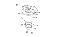
- FIG. 14 is a perspective view of the cap A5 according to the fifth embodiment of the present invention.
- FIG. 15 is a side view of the cap A5 according to the fifth embodiment of the present invention.
- FIG. 16 is a diagram showing a cross section taken along the line AA of FIG. In FIGS. 14 to 16, the same reference numerals are given to the configurations equivalent to the configurations shown in the above-described embodiments, and the description thereof will be omitted.
- the discharge unit 24 does not distinguish between the base unit 28 and the discharge port 29.
- the discharge portion 24 is formed in a cylindrical shape connected to the connection portion 23.
- the open end of the discharge portion 24 has a flat shape having a substantially constant outer diameter, unlike the caps A1 to A4 according to the first to fourth embodiments.
- the discharge hole 26 has a tapered shape in which the diameter narrows from the open end (second end 21 of the main body 18) of the discharge portion 24 toward the connection portion 23.
- the lid portion 56 may include a disk-shaped base portion 57 having an outer diameter larger than that of the discharge portion 24, and a plug portion 58 protruding from the lower surface of the base portion 57 (the surface facing the discharge hole 26). ..
- the outer peripheral portion 59 of the base portion 57 is configured to project in a flange shape to the outside of the discharge portion 24 in a state where the lid portion 56 is closed.
- the plug portion 58 is formed in a cylindrical shape having an opening 60 formed therein. Further, the plug portion 58 has a tapered shape in which the outer diameter narrows toward the tip of the plug portion 58.
- An annular film arranging portion 61 projecting upward is formed on the upper surface of the base portion 57.
- An opening 60 is formed in the lid portion 56 so as to continuously pass through the film arranging portion 61 and the plug portion 58.
- a hydrophobic film 45 is arranged in the film arranging portion 61 so as to close the opening 60. Further, the film arranging portion 61 has a larger outer diameter than the hydrophobic film 45.
- a covering member 62 is provided in the film arranging portion 61 so as to cover the hydrophobic film 45.
- the covering member 62 is formed in a disk shape having substantially the same outer diameter as the film arranging portion 61.
- the covering member 62 is joined to the outer peripheral portion of the film arranging portion 61 so that the outer peripheral portion thereof is in contact with the film arranging portion 61 and the central portion surrounded by the outer peripheral portion is in contact with the hydrophobic film 45.
- the covering member 62 may be joined to the film arranging portion 61 by, for example, heat welding, an adhesive, or the like.
- the covering member 62 is formed with a distribution port 63 that enables air to flow in the thickness direction of the covering member 62.
- the hydrophobic film 45 is exposed from the distribution port 63.
- the lid portion 56 can be closed by, for example, pinching the outer peripheral portion 59 of the base portion 57, folding the hinge mechanism 49, and pressing the upper surface of the base portion 57. By pushing the upper surface of the base portion 57, the plug portion 58 is inserted into the discharge hole 26. As a result, the discharge hole 26 can be closed. In this state, the urine introduction path 22 of the main body 18 and the opening 60 of the lid portion 56 communicate with each other as shown in FIG.
- FIG. 17 is a perspective view of the cap A6 according to the sixth embodiment of the present invention.
- FIG. 18 is a side view of the cap A6 according to the sixth embodiment of the present invention.
- FIG. 19 is a diagram showing a cross section taken along the line AA of FIG. In FIGS. 17 to 19, the same reference numerals are given to the configurations equivalent to the configurations shown in the above-described embodiments, and the description thereof will be omitted.
- the opening 60 closed by the hydrophobic film 45 is not formed in the lid portion 56, but is formed so as to be connected to the middle portion of the urine introduction path 22 of the main body 18. There is. More specifically, the opening 64 is formed so as to penetrate the side wall of the discharge portion 24 of the main body 18.
- the film arranging portion 65 is formed so as to project from the side wall of the main body 18. More specifically, the film arranging portion 65 includes a support 66 protruding from the side wall of the main body 18 (discharging portion 24) and a film arranging plate 67 formed in a flange shape with respect to the support 66. May be good.
- the support 66 is formed in a cylindrical shape, and the film arrangement plate 67 is formed in a disk shape.
- the opening 64 is formed so as to continuously pass through the side wall of the film arrangement plate 67, the support 66, and the main body 18.
- a hydrophobic film 45 is arranged on the film arrangement plate 67 so as to close the opening 64. Further, the film arranging plate 67 has a larger outer diameter than the hydrophobic film 45.
- a covering member 68 is provided on the film arranging plate 67 so as to cover the hydrophobic film 45.
- the covering member 68 is formed in a disk shape having substantially the same outer diameter as the film arranging plate 67.
- the covering member 68 is joined to the outer peripheral portion of the film arranging plate 67 so that the outer peripheral portion thereof is in contact with the film arranging plate 67 and the central portion surrounded by the outer peripheral portion is in contact with the hydrophobic film 45.
- the covering member 68 may be joined to the film arrangement plate 67 by, for example, heat welding, an adhesive, or the like.
- FIG. 20 is a perspective view of the cap A7 according to the seventh embodiment of the present invention.
- FIG. 21 is a plan view of the cap A7 according to the seventh embodiment of the present invention.
- FIG. 22 is a side view of the cap A7 according to the seventh embodiment of the present invention.
- FIG. 23 is a rear view of the cap A7 according to the seventh embodiment of the present invention.
- FIG. 24 is a diagram showing a cross section taken along the line AA of FIG.
- FIG. 25 is a diagram showing a BB cross section of FIG.
- the same reference numerals are given to the configurations equivalent to the configurations shown in the above-described embodiments, and the description thereof will be omitted.
- the lid portion 70 is formed with a so-called split septum structure. More specifically, the lid portion 70 may include a disk-shaped valve body 72 having an insertion hole (slit 71) formed in the central portion.
- the valve body 72 is made of an elastic material.
- the elastic material for example, latex rubber, isoprene rubber, silicone, thermoplastic elastomer (for example, styrene-based elastomer, etc.) can be used.
- Such a valve body 72 can be fixed to the open end of the discharge portion 24 of the main body 18, for example, by insert molding.
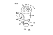
- FIG. 26 is a perspective view of the cap A8 according to the eighth embodiment of the present invention.
- FIG. 27 is a side view of the cap A8 according to the eighth embodiment of the present invention.
- 28 and 29 are views showing a cross section taken along the line AA of FIG. 26, FIG. 28 is a view seen from diagonally above, and FIG. 29 is a view seen from the side.
- FIGS. 26 to 29 the same reference numerals are given to the configurations equivalent to the configurations shown in the above-described embodiment, and the description thereof will be omitted.
- the lid portion 73 is formed with a so-called duckbill valve structure. More specifically, the lid portion 73 has a pair of inclined valve bodies 74 extending from the open end of the discharge portion 24 toward the connection hole 25 so as to converge. The pair of inclined valve bodies 74 are in contact with each other at the tip, and a slit 75 is formed at the tip.
- the inclined valve body 74 is made of an elastic material. As the elastic material, for example, latex rubber, isoprene rubber, silicone, thermoplastic elastomer (for example, styrene-based elastomer, etc.) can be used. Such an inclined valve body 74 can be fixed to the open end portion of the discharge portion 24 of the main body 18, for example, by insert molding.
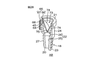
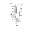
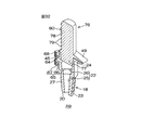
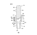
- FIG. 30 is a perspective view of the cap A9 according to the ninth embodiment of the present invention.
- FIG. 31 is a side view of the cap A9 according to the ninth embodiment of the present invention.
- 32 and 33 are views showing a cross section taken along the line AA of FIG. 30, FIG. 32 is a view seen from diagonally above, and FIG. 33 is a view seen from the side.
- FIGS. 30 to 33 the same reference numerals are given to the configurations equivalent to the configurations shown in the above-described embodiment, and the description thereof will be omitted.
- the lid portion 76 is formed in a stick shape. More specifically, the lid portion 76 has a plug portion 77 inserted into the discharge hole 26 and a columnar portion 78 connected to the plug portion 77.
- the plug portion 77 has a tapered shape in which the outer diameter narrows toward the tip of the plug portion 77.
- the columnar portion 78 is formed in a columnar shape having substantially the same length as the main body 18.
- a non-slip structure 80 composed of a plurality of ridges 79 is formed on a part of the side surface of the columnar portion 78.
- the plurality of ridges 79 are arranged at intervals in the length direction of the columnar portion 78.
- Each ridge 79 extends in the circumferential direction of the columnar portion 78.
- the stick-shaped lid portion 76 is integrally connected to the main body 18 via a hinge mechanism 49.
- the hinge mechanism 49 is connected to the opposite side of the non-slip structure 80 at the end of the columnar portion 78 on the plug portion 77 side.
- the lid portion 76 since the lid portion 76 has a stick shape, for example, the lid portion 76 can be easily opened with one hand by hanging the thumb on the non-slip structure 80 and pressing the lid portion 76 with the thumb. can.
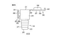
- [10th Embodiment] 34 and 35 are perspective views and side views of the cap A10 according to the tenth embodiment of the present invention, respectively, and show a state in which the lid portion 56 is opened.
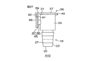
- 36 and 37 are perspective views and side views of the cap A10 according to the tenth embodiment of the present invention, respectively, and show a state in which the lid portion 56 is closed.
- FIGS. 34 to 37 the same reference numerals are given to the configurations equivalent to the configurations shown in the above-described embodiment, and the description thereof will be omitted.
- the first engaging portion 81 is formed on the peripheral edge portion of the film arrangement plate 67, and the second engaging portion 82 is formed on the outer peripheral portion 59 of the disk-shaped base portion 57.
- the first engaging portion 81 and the second engaging portion 82 engage with each other with the lid portion 56 closed. By this engagement, the lid portion 56 can be locked with respect to the main body 18.
- the hinge mechanism 49 is urged in the direction in which the lid portion 56 opens, the first engaging portion 81 and the second engaging portion 82 are engaged by pushing the film arrangement plate 67 like a button.
- the lid 56 can be opened by the urging force of the hinge mechanism 49. Since the lid 56 can be opened without directly touching it, it is possible to reliably prevent urine from adhering to the hand when the lid 56 is opened.
- Method of fixing the hydrophobic film 45 Next, another form of the method for fixing the hydrophobic film 45 is shown.
- the hydrophobic film 45 is fixed by covering with the covering members 46, 62, 68, but is fixed in another form as shown in FIGS. 38A to 38B and 39A to 39D. You can also do it.
- FIGS. 38A to 38B are diagrams for explaining a method of fixing the hydrophobic film 45 (first form).
- 39A to 39D are diagrams for explaining a method of fixing the hydrophobic film 45 (second form).
- the structure of the cap A5 of the fifth embodiment will be described as an example.
- FIG. 38A an integrally molded main body 18 and a lid portion 56, and a hydrophobic film 45 are prepared.
- the film arranging portion 83 surrounds the opening 60, for example, and is formed in an annular shape having an outer diameter substantially the same as that of the hydrophobic film 45.
- FIG. 38A an integrally molded main body 18 and a lid portion 56, and a hydrophobic film 45 are prepared.
- the film arranging portion 83 surrounds the opening 60, for example, and is formed in an annular shape having an outer diameter substantially the same as that of the hydrophobic film 45.
- FIG. 38A an integrally molded main body 18 and a lid portion 56, and a hydrophobic film 45
- FIG. 43 is a diagram showing a state of the catheter 1 at the time of disinfection.
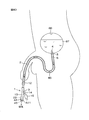
- FIGS. 40 to 43 the method of using the catheter 1 and the effect of attaching the caps A1 to A10 according to the above-described embodiment will be described.
- the caps A1 to A10 of the above-described embodiment are schematically shown as caps A11.
- the method of indwelling catheter urinary catheterization is shown as an example, but the method of inserting the catheter 1 into the urethra 85 is the same in the case of clean intermittent catheterization (CIC).
- CIC clean intermittent catheterization
- the shaft 2 is inserted into the urethra 85 in order from the cap 4.
- the catheter 1 can be hygienically inserted by inserting the shaft 2 while grasping it through the sleeve 12.
- the side hole 5 at the tip of the shaft 2 reaches the bladder 86
- the urine 87 in the bladder 86 is guided to the urinary catheter 7 (see FIGS. 2A and 2B) through the side hole 5.
- the urine 87 guided by the urinary catheter 7 moves downstream through the urinary lumen 7 and reaches the urine introduction path 22 (not shown) of the cap A11 via the urination base 13.
- the patient visually confirms that the urine 87 has reached the cap A11, and then inserts the catheter 1 a little further as shown in FIG. 41.
- the reason for this is that, as shown in FIG. 40, the balloon 6 may be located in the urethra 85 even if the side hole 5 of the catheter 1 reaches the inside of the bladder 86, and at that time, the balloon 6 is inflated. This is because the urethra 85 may be damaged.
- the balloon 6 is inflated with the sterilized water as shown in FIG. 42.
- the shaft 2 is prevented from coming off, and the catheter 1 is placed in the bladder 86.
- the urine 87 accumulated in the bladder 86 can be discharged.
- openings 43, 60, 64 are formed, and a hydrophobic film 45 is formed in the openings 43, 60, 64.
- the air in the catheter 1 can be released to the outside when the catheter 1 is inserted into the urethra 85, so that after the tip of the catheter 1 reaches the bladder 86 (see FIG. 40), the air in the bladder 86 is formed.
- the urine 87 can be smoothly guided to the caps A1 to A11.
- the urine 87 discharged from the bladder 86 is blocked by the hydrophobic film 45, the urine 87 can be retained by the urine introduction passages 22 of the caps A1 to A11.
- the next work can be performed slowly without being impatient.
- FIG. 44 is a perspective view of the cap B1 according to the eleventh embodiment of the present invention.
- FIG. 45 is a diagram showing a cross section taken along the line AA of FIG. 44.
- FIG. 46 is a perspective view of the cap B1 of FIG. 45.
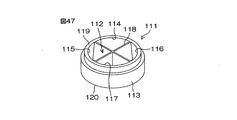
- FIG. 47 is a diagram for explaining the internal structure of the lid portion 111 of the cap B11 of FIG. 44.
- the covering member 301 (described later) covering the top surface of the lid portion 111 is omitted.
- FIGS. 44 to 47 the same reference numerals are given to the configurations equivalent to the configurations shown in the above-described embodiment, and the description thereof will be omitted.
- the bowl-shaped base portion 28 also serves as the discharge port 29 instead of the cylindrical discharge port 29 in the discharge portion 24. Therefore, the urine passing through the connection hole 25 is discharged through the discharge hole 26 formed by the inner wall surface of the base portion 28.
- the cap B1 further includes a lid portion 111 whose inside is divided into a plurality of spaces in place of the lid portion 19. More specifically, the lid portion 111 includes a base portion 113 and a partition portion 118.
- the base portion 113 is formed in a cylindrical shape in which the first end portion 119 and the second end portion 120 are open, and has a space 112 inside.
- the first end portion 119 of the base portion 113 is the upstream side (connection portion with the main body 18) when urine is discharged, and the second end portion 120 of the base portion 113 is the downstream side when urine is discharged. May be good.
- the partition portion 118 divides the space 112 into a plurality of spaces 114 to 117 when the base portion 113 is viewed in the axial direction.
- the partition portion 118 may include a partition plate erected between a plurality of locations on the inner peripheral surface of the base portion 113.
- the partition portion (partition plate) 118 includes a cross-shaped partition plate, and the space 112 is divided into four spaces 114 to 117.
- the circular base portion 113 in a plan view is divided into the cross-shaped partition portions 118, so that the space 112 is divided into four equal parts, and four fan-shaped spaces 114 to 117 congruent with each other are formed.
- the four spaces 114 to 117 may include a first space 114, a second space 115, a third space 116, and a fourth space 117.
- the partition portion 118 is, for example, a T-shaped partition plate
- the space 112 may be divided into three spaces, or may be divided into two spaces or five or more spaces. ..
- the hydrophobic film 45 is formed so as to cover at least two or more spaces of a plurality of spaces 114 to 117 at the second end portion 120 of the base portion 113.
- the hydrophobic film 45 is formed so as to span all of the four spaces 114 to 117.
- the hydrophobic film 45 is supported by a cross-shaped partition 118. Therefore, each space 114 to 117 is closed by the hydrophobic film 45 on the top surface side of the base portion 113. That is, when the cap B1 is turned upside down, the base portion 113 has a space 114 to 117 partitioned by a side wall 121 formed of the peripheral wall and the partition portion 118 of the base portion 113 and a bottom wall 122 made of the hydrophobic film 45. Is formed.
- the spaces 114 to 117 may be referred to as the first room 114, the second room 115, the third room 116, and the fourth room 117, respectively, because the bottom wall 122 is closed with the hydrophobic film 45.
- the plurality of spaces 114 to 117 may not be covered with the hydrophobic film 45 as long as at least two or more spaces are covered with the hydrophobic film 45.
- the bottom wall 122 of the first space 114 and the second space 115 is formed of the hydrophobic film 45
- the bottom wall 122 of the third space 116 and the fourth space 117 is the second end portion 120 of the base portion 113. It may be made of a plastic material that extends integrally from.
- each space 114 to 117 is preferably 50% or more of the volume of the urinary catheterization lumen 7 (see FIGS. 2A and 2B) of the shaft 2.
- the volume of each space 114 to 117 can be appropriately changed, for example, by adjusting the height of the partition portion 118 (partition wall).
- cap B1 is provided with the hydrophobic film 45 like the caps A1 to A11, when the catheter 1 shown in FIG. 43 is disinfected, the air inside the shaft 2 is externally provided through the hydrophobic film 45. Can be escaped to. As a result, the disinfectant solution 88 can be distributed inside the shaft 2 through the side hole 5 even while attached to the catheter 1.
- the disinfectant solution 88 in the shaft 2 of the catheter 1 cannot be completely removed, and a part remains.
- the remaining disinfectant 88 may flow down into the cap B1 due to its own weight. Therefore, the disinfectant solution 88 may adhere to the hydrophobic film 45 in the cap B1 and clog the hydrophobic film 45.
- the disinfectant liquid 88 is a relatively viscous liquid such as benzalkonium chloride-added glycerin (glycerin BC liquid)
- the hydrophobic film 45 is likely to be clogged.
- the lid portion 111 is divided into a plurality of spaces 114 to 117, and the bottom wall 122 of each space 114 to 117 is formed of the hydrophobic film 45.
- the disinfectant solution 88 can be prevented from flowing into all the spaces 114 to 117 by tilting the cap B1 at an angle, for example, as shown in FIG. 48. Can be done.
- clogging of the hydrophobic film 45 bottom wall 122 can be avoided in any of the spaces 114 to 117, so that the air permeability of the hydrophobic film 45 can be sufficiently ensured even after disinfection.
- FIG. 50 is a perspective view of the cap B2 according to the twelfth embodiment of the present invention.
- FIG. 51 is a diagram showing a cross section taken along the line AA of FIG.
- FIG. 52 is a perspective view of the cap B2 of FIG. 51.
- FIG. 53 is a diagram for explaining the internal structure of the lid portion 211 of the cap B2 of FIG. 50.
- the covering member 301 (described later) covering the top surface of the lid portion 211 is omitted.
- FIGS. 50 to 53 the same reference numerals are given to the configurations equivalent to the configurations shown in the above-described embodiment, and the description thereof will be omitted.
- the bowl-shaped base portion 28 also serves as the discharge port 29 instead of the cylindrical discharge port 29 in the discharge portion 24. Therefore, the urine passing through the connection hole 25 is discharged through the discharge hole 26 formed by the inner wall surface of the base portion 28.
- the cap B2 further includes a lid portion 211 whose inside is divided into a plurality of spaces in place of the lid portion 19. More specifically, the lid portion 211 includes a base portion 213 and a partition portion 218.
- the base portion 213 is formed in a cylindrical shape in which the first end portion 219 and the second end portion 220 are open, and has a space 212 inside.
- the first end portion 219 of the base portion 213 is the upstream side (connection portion with the main body 18) when urine is discharged, and the second end portion 220 of the base portion 213 is the downstream side when urine is discharged. May be good.
- the partition portion 218 divides the space 212 into a plurality of spaces 214 and 215 when the base portion 213 is viewed in the axial direction.
- the partition portion 218 may include a partition cylinder that is erected in the space 212 and is formed in a tubular shape having an axial direction in the same direction as the axial direction of the base portion 213.
- the partition portion as a partition cylinder separates the space inside the wall portion and the space outside the wall portion into spaces independent of each other by the tubular wall portion.
- the partition portion (partition cylinder) 218 includes a cylindrical partition cylinder, and the space 212 is divided into two spaces 214 and 215.
- the circular base portion 213 in a plan view is divided into the cylindrical partition portion 218, so that the space 212 is the first space 214 as a cylindrical space inside the partition portion 218 and the partition portion 218.
- a second space 215 as an outer annular space is formed.
- the partition portion 218 may have a square cylinder shape or a triangular cylinder shape, for example.
- the partition portion 218 is connected to the base portion 213 by a linear support portion 216 extending inward in the circumferential direction of the base portion 213 from the peripheral wall of the base portion 213. In this embodiment, four support portions 216 extending in all directions from the partition portion 218 support the partition portion 218.
- the hydrophobic film 45 is formed so as to cover the two spaces 214 and 215 at the second end 220 of the base portion 213.
- the hydrophobic film 45 is supported by a partition 218 and a support 216. Therefore, the spaces 214 and 215 are closed by the hydrophobic film 45 on the top surface side of the base portion 213. That is, when the cap B2 is turned upside down, the base portion 213 is formed with a side wall 221 formed of an inner peripheral wall of the partition portion 218 and a first space 214 partitioned by a bottom wall 222 made of a hydrophobic film 45. Has been done.
- a side wall 223 formed of an outer peripheral wall of the partition portion 218, a side wall 225 formed of a peripheral wall of the base portion 213, and a second space 215 partitioned by a bottom wall 224 made of a hydrophobic film 45 are formed.
- the spaces 214 and 215 may be referred to as the first room 214 and the second room 215, respectively, because the bottom walls 222 and 224 are closed by the hydrophobic film 45, respectively.
- each of the spaces 214 and 215 is preferably 50% or more of the volume of the urinary catheterization lumen 7 (see FIGS. 2A and 2B) of the shaft 2.
- the volumes of the spaces 214 and 215 can be appropriately changed, for example, by adjusting the height of the partition portion 218 (partition cylinder).
- the lid portion 211 is divided into a plurality of spaces 214 and 215, and the bottom walls 222 and 224 of the respective spaces 214 and 215 are formed of the hydrophobic film 45.
- FIG. 54 is a perspective view of the cap B3 according to the thirteenth embodiment of the present invention.
- FIG. 55 is a perspective view of the cap B3 according to the thirteenth embodiment of the present invention.
- FIG. 56 is a plan view of the cap B3 according to the thirteenth embodiment of the present invention.
- FIG. 57 is a side view of the cap B3 according to the thirteenth embodiment of the present invention.
- FIG. 58 is a diagram showing a cross section taken along the line AA of FIG. 56.
- FIG. 59 is an exploded view of the cap B3 according to the thirteenth embodiment of the present invention. Further, in FIGS. 54 to 59, the same reference numerals are given to the configurations equivalent to the configurations shown in the above-described embodiment, and the description thereof will be omitted.
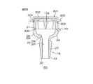
- the lid portion 111 of the cap B3 includes a cap-shaped covering member 301 that covers the top surface of the base portion 113. Since the covering member 301 covers and protects the hydrophobic film 45, it may be referred to as a protective member.
- the covering member 301 is formed in an annular shape having a top wall portion 302. The opposite side of the top wall portion 302 of the covering member 301 is an open connecting portion 303.
- a recess 304 is formed in a circular shape over the entire circumference of the base 113 in the circumferential direction.
- the covering member 301 can be fixed to the base portion 113 by fitting the concave groove 304 and the connecting portion 303.
- the covering member 301 has a flange portion 305 protruding outward from the annular portion. The patient can open the lid 111, for example, by hooking his thumb on the flange 305.
- the lid portion 111 According to the cap B3, from the opening / closing position 306 of the lid portion 111 in the cap B3 (in this embodiment, the connection position between the first end portion 119 of the base portion 113 and the second end portion 21 of the main body 18), the lid portion 111
- the flange portion 305 for opening and closing is separated.
- the flange portion 305 is separated from the opening / closing position 306 by the height of the base portion 113. Therefore, when the lid portion 111 is opened and the urine is discharged, it is possible to prevent the urine from coming into contact with the hand.
- the same effect can be exhibited by a protruding portion that selectively protrudes outward from the annular portion of the covering member 301.
- the hat-shaped covering member 301 having the flange portion 305 exerts the above effect, but the cap-shaped covering member 301 can also exert the same effect.
- variations of the covering member 301 of the cap B3 will be described with reference to FIGS. 60 to 68.
- the covering member 301 may be the following covering members 311, 321, 331.
- the covering member 301 shown in FIGS. 54 to 59 may be a covering member 311. (First form) FIG.
- FIG. 60 is a diagram showing a first form of the covering member 311 of the cap of FIG. 55.
- FIG. 61 is a cross-sectional view showing a cross section taken along the line AA of FIG. 60.
- FIG. 62 is a cross-sectional view showing a cross section taken along the line AA of FIG. 60.
- the covering member 311 is a member that protects the hydrophobic film 45 and secures the flow of air inside and outside the cap B3.
- the covering member 311 is formed in an annular shape having a top wall portion 312.
- the opposite side of the top wall portion 312 of the covering member 311 is an open connecting portion 313.
- the covering member 311 may have a cylindrical shape.
- One of the covering members 311 has a space 314 closed by the top wall portion 312.
- the hydrophobic film 45 is housed in the space 314 in a state of being covered with the top wall portion 312.
- the covering member 311 includes a flange portion 315 protruding outward from the outer peripheral surface thereof.
- the flange portion 315 is an annular shape formed over the entire outer peripheral surface of the covering member 311.
- the top wall portion 312 of the covering member 311 is a plain surface having no holes formed on its flat upper surface 317.
- the "plane surface” means that the upper surface 317 of the top wall portion 312 is not formed with an opening for distribution with the space 314, and the entire upper surface 317 is formed of a material constituting the covering member 311. It may mean that it is.
- a circulation port 316 for ensuring the flow of air inside and outside the space 314 is formed on the peripheral surface 318 of the covering member 311.
- the distribution port 316 is formed on the top wall portion 312 side with respect to the flange portion 315 when the covering member 311 is divided into the top wall portion 312 side and the connection portion 313 side with the flange portion 315 as a boundary.
- the distribution port 316 may be referred to as a lateral hole formed in the horizontal direction along the upper surface 317 of the top wall portion 312 and forming an air flow in the lateral direction.
- a plurality of distribution ports 316 are formed at intervals in the circumferential direction of the covering member 311.
- FIG. 63 is a diagram showing a second form of the covering member 321 of the cap of FIG. 55.
- FIG. 64 is a cross-sectional view showing a cross section taken along the line AA of FIG. 63.
- FIG. 65 is a cross-sectional view showing a cross section taken along the line AA of FIG. 63.
- the same reference numerals are given to the same configurations as those of the covering member 311 described above, and the description thereof will be omitted.
- the covering member 321 includes a top wall portion 322 having a hole-formed upper surface portion 323 instead of the top wall portion 312 having a plain surface (upper surface 317).
- a plurality of distribution ports 324 and 325 are formed on the upper surface 323.
- the distribution ports 324 and 325 may be referred to as vertical holes formed in the vertical direction penetrating the top wall portion 322 in the thickness direction and forming an air flow in the vertical direction.
- the distribution ports 324 and 325 may include a first distribution port 324 and a second distribution port 325 having different diameters from each other.
- a plurality of first distribution ports 324 having a relatively small diameter are formed in the central portion of the top wall portion 322.
- the second distribution port 325 which has a diameter relatively larger than that of the first distribution port 324, may be formed so as to surround the first distribution port 324.
- FIG. 66 is a diagram showing a third form of the covering member 331 of the cap of FIG. 55.
- FIG. 67 is a cross-sectional view showing a cross section taken along the line AA of FIG. 66.
- FIG. 68 is a cross-sectional view showing a cross section taken along the line AA of FIG.
- the same reference numerals are given to the same configurations as those of the covering member 311 described above, and the description thereof will be omitted.
- the covering member 331 includes a top wall portion 332 having a top surface 333 having holes formed in place of the top wall portion 312 having a plain surface (upper surface 317).
- a plurality of distribution ports 334 are formed on the upper surface 333.
- the distribution port 334 may be referred to as a vertical hole formed in the vertical direction penetrating the top wall portion 332 in the thickness direction and forming an air flow in the vertical direction.
- the plurality of distribution ports 334 have the same diameter as each other.
- the plurality of distribution ports 334 are formed in a regular arrangement in the central portion of the top wall portion 332.
- the hydrophobic film 45 since the hydrophobic film 45 is housed in the space 314 inside the covering member 331, the hydrophobic film 45 cannot be directly touched by a finger or the like. Thereby, the hydrophobic film 45 can be protected. [Performance of Hydrophobic Film 45] In the above-described embodiment, an example of the material of the hydrophobic film 45 and physical quantities such as thickness and pore size is shown.
- the hydrophobic film 45 may be formed of a known hydrophobic film material such as polytetrafluoroethylene (PTFE), acrylic copolymer, polyether sulfone (PES), and glass fiber.
- PTFE polytetrafluoroethylene
- acrylic copolymer acrylic copolymer
- PES polyether sulfone
- glass fiber glass fiber
- the diameter (pore diameter) of the pores formed in the hydrophobic film 45 may be 0.05 ⁇ m to 50 ⁇ m.
- the thickness of the hydrophobic film 45 may be 0.01 mm to 2 mm.
- the hydrophobic film 45 has an air flow rate (garley value) measured in accordance with JIS P8117 (Garley method) of 0.1 seconds to 500 seconds / 100 mL, and JIS L 1092-B (high water pressure).
- the water pressure resistance measured in accordance with the method) is preferably 0.1 kPa or more (more preferably 0.1 kPa to 500 kPa).
- the water repellency indicates, for example, the difficulty of infiltration of the disinfectant solution into the hydrophobic film 45 (easiness of repelling the disinfectant solution) when the disinfectant solution (same as the disinfectant solution 88) is dropped on the hydrophobic film 45. It is a physical property and can be evaluated visually. For example, when the disinfectant solution dropped on the surface of the hydrophobic film 45 maintains a spherical shape on the surface of the hydrophobic film 45 due to surface tension, it can be said that the water repellency is high.
- the long-term water repellency is, for example, a physical property that indicates difficulty in infiltration of the disinfectant solution into the hydrophobic film 45 (easiness of repelling the disinfectant solution) when the hydrophobic film 45 is brought into contact with the disinfectant solution for a long time. Yes, it can be evaluated visually. For example, after exposing the hydrophobic film 45 to the disinfectant solution for about one month, if it can be visually confirmed that the surface of the hydrophobic film 45 is not covered with the disinfectant solution, it can be said that the long-term water repellency is high.
- the pressure resistance is, for example, a physical property that indicates the difficulty of liquid leakage through the hydrophobic film 45 when a hydraulic pressure is applied to the hydrophobic film 45, and can be visually evaluated.
- the following method can be mentioned as an example of the evaluation method.
- the catheter 1 to which the caps A1 to A11 and B1 to B3 are attached is attached to the case 89 containing the disinfectant solution 88.
- the inside of the case 89 becomes positive pressure when the case 89 is folded.
- the pressure resistance is relatively low.
- Breathability is, for example, a physical property indicating whether or not urine 87 in the bladder 86 is smoothly guided to caps A1 to A11 and B1 to B3, and can be visually evaluated.
- the catheter 1 is inserted into one's urethra 85, if urine reaches caps A1 to A11 and B1 to B3 so as to continuously flow from the bladder 86, it can be said that the air permeability is high.
- urine reaches caps A1 to A11 and B1 to B3 but the flow is intermittently dropped, it can be said that the air permeability is not high.
- a hydrophobic film 45 having a thickness of 10 ⁇ m to 2 mm, an aeration rate of 0.1 seconds to 500 seconds / 100 mL, and a water pressure resistance of 0.1 kPa or more is capped (either of caps A1 to A11 and B1 to B3).
- the caps A1 to A11 and B1 to B3 are formed of a translucent resin, and substances having a function of developing color by the action of water are contained in the caps A1 to A1 to B3.
- the arrival of urine to the caps A1 to A11 and B1 to B3 can be easily confirmed visually by containing the material in A11 and B1 to B3 or forming a textured surface on the inner surface of the urine introduction path 22. can do.
- the caps A1 to A11 and B1 to B3 may be provided with the detecting means 90 and the transmitting means 91, for example, as shown in FIG. 69.
- the detection means 90 may be a device that can detect the arrival of urine without contacting urine (for example, an optical device such as a photo interrupter).
- the transmitting means 91 may be capable of transmitting urine arrival information based on the detection of the detecting means 90.
- the transmission means 91 may be a wireless communication device that wirelessly transmits the arrival information of urine 87 to a mobile terminal such as a tablet or a personal computer.
- the detection means 90 and the transmission means 91 are provided in this way, various information can be obtained depending on the type of the transmission means 91.
- the transmitting means 91 is a sounding means, the arrival of urine can be easily confirmed by hearing, and when the transmitting means 91 is a vibrating means, the arrival of urine can be easily confirmed by skin sensation. Can be done.
- the transmitting means 91 is a wireless transmitting means, the medical staff or the patient himself / herself can indirectly obtain objective information as to whether or not the catheter 1 is correctly inserted.
- the extension attachment 94 may be connected to the connection hole 25 of the main body 18.
- the extension attachment 94 is formed in a cylindrical shape having a connection side end portion 95 connected to the connection hole 25 and a discharge side end portion 96 on the opposite side thereof.
- the extension attachment 94 is formed in a tapered shape whose diameter gradually increases toward the discharge side end portion 96.
- the extension attachment 94 can extend the urine introduction path 22 and connect the urine collection bag with the caps A1 to A11 and B1 to B3 attached.
Landscapes
- Health & Medical Sciences (AREA)
- Heart & Thoracic Surgery (AREA)
- Life Sciences & Earth Sciences (AREA)
- Animal Behavior & Ethology (AREA)
- Public Health (AREA)
- Biomedical Technology (AREA)
- Hematology (AREA)
- Engineering & Computer Science (AREA)
- Veterinary Medicine (AREA)
- General Health & Medical Sciences (AREA)
- Anesthesiology (AREA)
- Pulmonology (AREA)
- Biophysics (AREA)
- Epidemiology (AREA)
- Urology & Nephrology (AREA)
- Otolaryngology (AREA)
- External Artificial Organs (AREA)
Priority Applications (3)
| Application Number | Priority Date | Filing Date | Title |
|---|---|---|---|
| JP2022516844A JP7731141B2 (ja) | 2020-04-23 | 2020-12-25 | 尿道カテーテル用キャップ |
| US17/920,168 US12544551B2 (en) | 2020-04-23 | 2020-12-25 | Urinary catheter cap |
| EP20932778.2A EP4140529A4 (en) | 2020-04-23 | 2020-12-25 | URINARY CATHETER CAP |
Applications Claiming Priority (2)
| Application Number | Priority Date | Filing Date | Title |
|---|---|---|---|
| JP2020076920 | 2020-04-23 | ||
| JP2020-076920 | 2020-04-23 |
Publications (1)
| Publication Number | Publication Date |
|---|---|
| WO2021215052A1 true WO2021215052A1 (ja) | 2021-10-28 |
Family
ID=78270708
Family Applications (1)
| Application Number | Title | Priority Date | Filing Date |
|---|---|---|---|
| PCT/JP2020/048769 Ceased WO2021215052A1 (ja) | 2020-04-23 | 2020-12-25 | 尿道カテーテル用キャップ |
Country Status (4)
| Country | Link |
|---|---|
| US (1) | US12544551B2 (https=) |
| EP (1) | EP4140529A4 (https=) |
| JP (1) | JP7731141B2 (https=) |
| WO (1) | WO2021215052A1 (https=) |
Cited By (3)
| Publication number | Priority date | Publication date | Assignee | Title |
|---|---|---|---|---|
| WO2024143199A1 (ja) * | 2022-12-28 | 2024-07-04 | 株式会社 塚田メディカル・リサーチ | 医療器具用キャップ |
| EP4552678A1 (en) * | 2023-11-10 | 2025-05-14 | Tik d.o.o. | Catheter assembly |
| WO2025248922A1 (ja) * | 2024-05-29 | 2025-12-04 | 株式会社 塚田メディカル・リサーチ | 医療器具用キャップ |
Families Citing this family (2)
| Publication number | Priority date | Publication date | Assignee | Title |
|---|---|---|---|---|
| GB202105821D0 (en) * | 2021-04-23 | 2021-06-09 | Convatec Ltd | Intermittent catheter |
| US12539381B2 (en) * | 2021-09-15 | 2026-02-03 | Naoyuki Ishikita | Suction-target guide pipe and suction-target suction system |
Citations (11)
| Publication number | Priority date | Publication date | Assignee | Title |
|---|---|---|---|---|
| JPS5851737U (ja) * | 1981-10-05 | 1983-04-08 | 住友ベークライト株式会社 | 生体液等の排出用導管 |
| US5429620A (en) * | 1994-08-03 | 1995-07-04 | Uroquest Corporation | Calibrated disconnect joint for urethral catheter |
| JPH09206370A (ja) * | 1995-12-01 | 1997-08-12 | Tsukada Medical Res:Kk | 人体留置医療器具用キャップ |
| JP2002017865A (ja) * | 2000-07-11 | 2002-01-22 | Fuji Systems Kk | 血管挿入用カニューレ |
| JP2004236999A (ja) | 2003-02-10 | 2004-08-26 | Create Medic Co Ltd | 自己導尿用カテーテルのキャップ |
| US20070161949A1 (en) * | 2006-01-06 | 2007-07-12 | Knox Susan J | Catheter system for minimizing retrograde bacterial transmission from a catheter tubing |
| JP5318925B2 (ja) | 2011-08-25 | 2013-10-16 | 和宏 久保 | 尿道カテーテル |
| US20140235960A1 (en) * | 2013-02-15 | 2014-08-21 | Pneumoflex Systems, Llc | Device to block emesis and reflux and associated system and method |
| WO2015075841A1 (ja) * | 2013-11-25 | 2015-05-28 | 独立行政法人国立病院機構 | 間欠自己導尿カテーテル |
| JP2015532876A (ja) * | 2012-10-25 | 2015-11-16 | バイエル メディカル ケア インコーポレーテッド | カテーテルおよび関連の機器 |
| JP2020076920A (ja) | 2018-11-09 | 2020-05-21 | 住友化学株式会社 | 垂直配向液晶硬化膜およびそれを含む積層体 |
Family Cites Families (53)
| Publication number | Priority date | Publication date | Assignee | Title |
|---|---|---|---|---|
| US3598124A (en) * | 1968-02-01 | 1971-08-10 | Andersen Prod H W | Drainage control |
| US3952902A (en) * | 1974-04-26 | 1976-04-27 | Cutter Laboratories, Inc. | Closure cap for plasma receiving assembly |
| US4262668A (en) * | 1979-04-06 | 1981-04-21 | Baxter Travenol Laboratories, Inc. | Fixed volume infusion device |
| DE3147499A1 (de) * | 1981-12-01 | 1983-06-09 | B. Braun Melsungen Ag, 3508 Melsungen | "entlueftungseinrichtung fuer ein medizinisches fluessigkeitssystem" |
| JPS58162836U (ja) | 1982-04-26 | 1983-10-29 | 株式会社ニツシヨ− | 尿バツグ |
| US4685472A (en) * | 1984-01-23 | 1987-08-11 | Rudolph Muto | Specimen collector |
| DE3832028A1 (de) * | 1988-09-21 | 1990-03-22 | Minh Bach Dr Ing Dr Med Quang | Vorrichtung zum entlueften von in medizinischen fluessigkeitssystemen stroemenden fluessigkeiten |
| US4934545A (en) * | 1989-01-19 | 1990-06-19 | Abbott Laboratories | Closure with microbial filter |
| US5290253A (en) * | 1989-06-09 | 1994-03-01 | Terumo Kabushiki Kaisha | Cap for medical tool connection and medical tool |
| US5125415A (en) * | 1990-06-19 | 1992-06-30 | Smiths Industries Medical Systems, Inc. | Syringe tip cap with self-sealing filter |
| EP0709076A4 (en) * | 1993-06-30 | 1997-07-16 | Suyamasaburoshoten Co Ltd | EXTRACTOR FOR BAGS FOR AN ARTIFICIAL OUTPUT |
| JP3781803B2 (ja) | 1994-07-04 | 2006-05-31 | 株式会社塚田メディカル・リサーチ | 人体留置医療器具用磁気キャップ |
| US5417678A (en) * | 1994-07-15 | 1995-05-23 | Minnesota Mining And Manufacturing Company | Low profile ostomy filter |
| EP0734769B1 (de) * | 1995-03-31 | 2002-11-27 | Roche Diagnostics GmbH | System und Verfahren zum Verschluss von Gefässen |
| DE29505787U1 (de) * | 1995-04-04 | 1995-06-01 | B. Braun Melsungen Ag, 34212 Melsungen | Verschlußstück |
| IT235830Y1 (it) * | 1995-04-06 | 2000-07-18 | Borla Ind | "raccordo luer-lock con cappuccio di protezione per linee medicali diinfusione-trasfusione." |
| ATE283346T1 (de) * | 1995-09-22 | 2004-12-15 | Us Gov Health & Human Serv | Gefäss zur trocknung von biologischer proben, verfahren zur herstellung desselben und verfahren zu seinem gebrauch |
| CA2169699A1 (en) | 1995-12-01 | 1997-06-02 | Osamu Tsukada | Cap for medical appliance to be retained in human body |
| CA2206612C (en) * | 1997-05-30 | 2003-12-09 | Joseph A. Martell | Filtering and deodorizing device for use with colostomy pouch |
| JP2002191905A (ja) * | 2000-12-28 | 2002-07-10 | Nipro Corp | 液循環回路用エアートラップ |
| US7311698B2 (en) | 2001-09-24 | 2007-12-25 | Coloplast A/S | Urinary catheter assembly allowing for non-contaminated insertion of the catheter into a urinary canal |
| AU2003252546B2 (en) * | 2002-08-09 | 2007-01-25 | E-Wha Fresenius Kabi Inc. | Cap of tube for supplying liquid |
| JP2006504455A (ja) * | 2002-10-29 | 2006-02-09 | バソジェン アイルランド リミテッド | 医療流体からのガスの放出を制御する装置及び方法 |
| US8282608B2 (en) * | 2004-01-29 | 2012-10-09 | Becton, Dickinson And Company | Self priming intravenous delivery system |
| JP3723200B1 (ja) * | 2004-09-30 | 2005-12-07 | 株式会社アルコア・クロージャー・システムズ | キャップおよび飲料入り閉止装置 |
| US8961491B2 (en) | 2006-04-21 | 2015-02-24 | Bayer Medical Care Inc | Catheters and related equipment |
| EP2121079A1 (en) * | 2006-11-30 | 2009-11-25 | Medi-Physics, Inc. | Dual-lumen needle |
| EP2101711A1 (en) * | 2006-11-30 | 2009-09-23 | Medi-Physics, Inc. | Dual-lumen needle with an elongate notch opening |
| US9572904B2 (en) * | 2008-05-06 | 2017-02-21 | Michael J. Ferlic | Sterilizing device with pinch actuated cap and housing |
| EP2366424A4 (en) * | 2008-11-05 | 2012-12-26 | Jms Co Ltd | AIR-PERMEABLE STRUCTURE AND METHOD OF FORMING AIR-PERMEABLE STRUCTURE |
| EP2371408B1 (en) * | 2010-03-31 | 2013-07-31 | Roche Diagnostics GmbH | Liquid drug degasing devise and ambulatory infusion system including a degasing device |
| US20110276010A1 (en) * | 2010-05-06 | 2011-11-10 | Becton, Dickinson And Company | Systems and methods for providing a closed venting hazardous drug iv set |
| JP5804675B2 (ja) | 2010-05-27 | 2015-11-04 | 日本コヴィディエン株式会社 | コネクター用キャップ及びこれを備えた輸液ラインの接続装置 |
| US9220866B2 (en) * | 2010-11-04 | 2015-12-29 | Curan Medical B.V. | Package with catheter |
| EP2554214A1 (en) * | 2011-08-04 | 2013-02-06 | B. Braun Melsungen AG | Needle free connector with a collapsible resilient membrane fitting and corresponding method |
| CN203107819U (zh) * | 2012-12-26 | 2013-08-07 | 北京伏尔特技术有限公司 | 自动止液护帽 |
| JP6163198B2 (ja) | 2013-02-28 | 2017-07-12 | テルモ株式会社 | キャップ |
| JP2014212873A (ja) | 2013-04-24 | 2014-11-17 | 株式会社塚田メディカル・リサーチ | 蓄尿袋 |
| CN203694250U (zh) * | 2014-01-09 | 2014-07-09 | 江苏苏云医疗器材有限公司 | 一种新型自排气式留置针 |
| US20150320926A1 (en) * | 2014-02-10 | 2015-11-12 | Terumo Cardiovascular Systems Corporation | Vented cap for cannula used in perfusion circuit |
| WO2015127285A1 (en) * | 2014-02-20 | 2015-08-27 | Repro-Med Systems, Inc. | Connector with filter |
| CN103990226A (zh) * | 2014-06-10 | 2014-08-20 | 倪新华 | 排气阻菌帽 |
| WO2016019138A1 (en) * | 2014-07-30 | 2016-02-04 | Covidien Lp | Vented connector for feeding syringe |
| CN104606739A (zh) * | 2015-01-17 | 2015-05-13 | 陈伟权 | 一种静脉留置针用防血拴安全盖及其使用方法 |
| US10702689B2 (en) * | 2015-03-26 | 2020-07-07 | Becton, Dickinson And Company | Auto-stop vent plug |
| JP6620237B2 (ja) * | 2015-10-30 | 2019-12-11 | シー・アール・バード・インコーポレーテッドC R Bard Incorporated | 通気アダプタ組立体、通気アダプタ組立体を作製する方法、通気アダプタ組立体を使用する方法及び通気アダプタ組立体を使用する排尿バッグシステム |
| JP6724564B2 (ja) * | 2016-05-31 | 2020-07-15 | セイコーエプソン株式会社 | ボトルセット |
| CN107754049A (zh) * | 2016-12-27 | 2018-03-06 | 上海交通大学 | 防止留置针正压接头污染的装置及基于该装置的方法 |
| EP3548133B1 (en) * | 2017-01-19 | 2026-02-25 | Potrero Medical, Inc. | Systems, devices and methods for draining and analyzing bodily fluids |
| JP2019050941A (ja) | 2017-09-13 | 2019-04-04 | 株式会社ジェイ・エム・エス | 医療機器用キャップ及び医療機器 |
| US20200338227A1 (en) * | 2017-10-06 | 2020-10-29 | Pinaki R. Majhi | Materials and methods for deoderization of mammalian urine |
| EP4028104A4 (en) * | 2019-09-10 | 2023-12-13 | MedSource International LLC | INTRAVENOUS CATHETER DEVICE |
| JP3224825U (ja) * | 2019-11-05 | 2020-01-23 | 株式会社塚田メディカル・リサーチ | 医療器具用キャップ |
-
2020
- 2020-12-25 JP JP2022516844A patent/JP7731141B2/ja active Active
- 2020-12-25 WO PCT/JP2020/048769 patent/WO2021215052A1/ja not_active Ceased
- 2020-12-25 EP EP20932778.2A patent/EP4140529A4/en not_active Withdrawn
- 2020-12-25 US US17/920,168 patent/US12544551B2/en active Active
Patent Citations (11)
| Publication number | Priority date | Publication date | Assignee | Title |
|---|---|---|---|---|
| JPS5851737U (ja) * | 1981-10-05 | 1983-04-08 | 住友ベークライト株式会社 | 生体液等の排出用導管 |
| US5429620A (en) * | 1994-08-03 | 1995-07-04 | Uroquest Corporation | Calibrated disconnect joint for urethral catheter |
| JPH09206370A (ja) * | 1995-12-01 | 1997-08-12 | Tsukada Medical Res:Kk | 人体留置医療器具用キャップ |
| JP2002017865A (ja) * | 2000-07-11 | 2002-01-22 | Fuji Systems Kk | 血管挿入用カニューレ |
| JP2004236999A (ja) | 2003-02-10 | 2004-08-26 | Create Medic Co Ltd | 自己導尿用カテーテルのキャップ |
| US20070161949A1 (en) * | 2006-01-06 | 2007-07-12 | Knox Susan J | Catheter system for minimizing retrograde bacterial transmission from a catheter tubing |
| JP5318925B2 (ja) | 2011-08-25 | 2013-10-16 | 和宏 久保 | 尿道カテーテル |
| JP2015532876A (ja) * | 2012-10-25 | 2015-11-16 | バイエル メディカル ケア インコーポレーテッド | カテーテルおよび関連の機器 |
| US20140235960A1 (en) * | 2013-02-15 | 2014-08-21 | Pneumoflex Systems, Llc | Device to block emesis and reflux and associated system and method |
| WO2015075841A1 (ja) * | 2013-11-25 | 2015-05-28 | 独立行政法人国立病院機構 | 間欠自己導尿カテーテル |
| JP2020076920A (ja) | 2018-11-09 | 2020-05-21 | 住友化学株式会社 | 垂直配向液晶硬化膜およびそれを含む積層体 |
Non-Patent Citations (1)
| Title |
|---|
| See also references of EP4140529A4 |
Cited By (3)
| Publication number | Priority date | Publication date | Assignee | Title |
|---|---|---|---|---|
| WO2024143199A1 (ja) * | 2022-12-28 | 2024-07-04 | 株式会社 塚田メディカル・リサーチ | 医療器具用キャップ |
| EP4552678A1 (en) * | 2023-11-10 | 2025-05-14 | Tik d.o.o. | Catheter assembly |
| WO2025248922A1 (ja) * | 2024-05-29 | 2025-12-04 | 株式会社 塚田メディカル・リサーチ | 医療器具用キャップ |
Also Published As
| Publication number | Publication date |
|---|---|
| JPWO2021215052A1 (https=) | 2021-10-28 |
| US20230173246A1 (en) | 2023-06-08 |
| EP4140529A1 (en) | 2023-03-01 |
| JP7731141B2 (ja) | 2025-08-29 |
| EP4140529A4 (en) | 2024-05-29 |
| US12544551B2 (en) | 2026-02-10 |
Similar Documents
| Publication | Publication Date | Title |
|---|---|---|
| WO2021215052A1 (ja) | 尿道カテーテル用キャップ | |
| EP3790516B1 (en) | Device for a male urinary incontinence device | |
| CN103974739B (zh) | 止液器 | |
| AU2019262946B2 (en) | Fluid collection devices, systems, and methods | |
| US9987480B2 (en) | Pressure controlled magnetic valve for a catheter | |
| JP4359285B2 (ja) | 間欠尿道留置カテーテルセット | |
| US10076636B2 (en) | Compact catheter assembly with adjustable catheter tube | |
| US20110301572A1 (en) | Medication delivery device | |
| JP2013501572A (ja) | 内部に含水流体の貯蔵場所を有するカテーテルおよび/またはこのカテーテルを使用するカテーテルパッケージおよびこのカテーテルの作製方法および/または使用方法 | |
| AU2002352915A1 (en) | Pad for use with continent ostomy port | |
| US6343704B1 (en) | Infant feeding nipple | |
| DK2683435T3 (en) | Devices for aseptic irrigation, urine sampling and urinary flow management from a catheterized bladder | |
| JPWO2019049955A1 (ja) | 尿道カテーテル | |
| EP4120968B1 (en) | Ostomy bag vent system for use in venting a gas from an interior of an ostomy collection pouch | |
| JP3759735B2 (ja) | 医療用逆止弁 | |
| KR101392386B1 (ko) | 착용식 소변장치 | |
| US20060095019A1 (en) | Urinary catheter | |
| KR20240132299A (ko) | 유량 조절 가능한 요도 카테터 | |
| JP7389308B2 (ja) | 薬剤注入器具 | |
| EP4552678A1 (en) | Catheter assembly | |
| KR102233114B1 (ko) | 소변 주머니 | |
| WO2024143199A1 (ja) | 医療器具用キャップ | |
| JP2025004472A (ja) | 医療器具用キャップ | |
| CN121712538A (zh) | 用于灌洗用户的肠道的便携式系统 | |
| CN115720513A (zh) | 用于男性尿失禁装置的装置 |
Legal Events
| Date | Code | Title | Description |
|---|---|---|---|
| 121 | Ep: the epo has been informed by wipo that ep was designated in this application |
Ref document number: 20932778 Country of ref document: EP Kind code of ref document: A1 |
|
| ENP | Entry into the national phase |
Ref document number: 2022516844 Country of ref document: JP Kind code of ref document: A |
|
| NENP | Non-entry into the national phase |
Ref country code: DE |
|
| ENP | Entry into the national phase |
Ref document number: 2020932778 Country of ref document: EP Effective date: 20221123 |
|
| WWW | Wipo information: withdrawn in national office |
Ref document number: 2020932778 Country of ref document: EP |
|
| WWG | Wipo information: grant in national office |
Ref document number: 17920168 Country of ref document: US |