WO2021201045A1 - 車両用変速機の操作装置及び車両 - Google Patents
車両用変速機の操作装置及び車両 Download PDFInfo
- Publication number
- WO2021201045A1 WO2021201045A1 PCT/JP2021/013708 JP2021013708W WO2021201045A1 WO 2021201045 A1 WO2021201045 A1 WO 2021201045A1 JP 2021013708 W JP2021013708 W JP 2021013708W WO 2021201045 A1 WO2021201045 A1 WO 2021201045A1
- Authority
- WO
- WIPO (PCT)
- Prior art keywords
- gear
- vehicle
- shift
- operating device
- bracket
- Prior art date
- Legal status (The legal status is an assumption and is not a legal conclusion. Google has not performed a legal analysis and makes no representation as to the accuracy of the status listed.)
- Ceased
Links
Images




Classifications
-
- B—PERFORMING OPERATIONS; TRANSPORTING
- B60—VEHICLES IN GENERAL
- B60K—ARRANGEMENT OR MOUNTING OF PROPULSION UNITS OR OF TRANSMISSIONS IN VEHICLES; ARRANGEMENT OR MOUNTING OF PLURAL DIVERSE PRIME-MOVERS IN VEHICLES; AUXILIARY DRIVES FOR VEHICLES; INSTRUMENTATION OR DASHBOARDS FOR VEHICLES; ARRANGEMENTS IN CONNECTION WITH COOLING, AIR INTAKE, GAS EXHAUST OR FUEL SUPPLY OF PROPULSION UNITS IN VEHICLES
- B60K20/00—Arrangement or mounting of change-speed gearing control devices in vehicles
- B60K20/02—Arrangement or mounting of change-speed gearing control devices in vehicles of initiating means
-
- F—MECHANICAL ENGINEERING; LIGHTING; HEATING; WEAPONS; BLASTING
- F16—ENGINEERING ELEMENTS AND UNITS; GENERAL MEASURES FOR PRODUCING AND MAINTAINING EFFECTIVE FUNCTIONING OF MACHINES OR INSTALLATIONS; THERMAL INSULATION IN GENERAL
- F16H—GEARING
- F16H59/00—Control inputs to control units of change-speed- or reversing-gearings for conveying rotary motion
- F16H59/02—Selector apparatus
- F16H59/08—Range selector apparatus
- F16H59/10—Range selector apparatus comprising levers
-
- F—MECHANICAL ENGINEERING; LIGHTING; HEATING; WEAPONS; BLASTING
- F16—ENGINEERING ELEMENTS AND UNITS; GENERAL MEASURES FOR PRODUCING AND MAINTAINING EFFECTIVE FUNCTIONING OF MACHINES OR INSTALLATIONS; THERMAL INSULATION IN GENERAL
- F16H—GEARING
- F16H61/00—Control functions within control units of change-speed- or reversing-gearings for conveying rotary motion ; Control of exclusively fluid gearing, friction gearing, gearings with endless flexible members or other particular types of gearing
- F16H61/02—Control functions within control units of change-speed- or reversing-gearings for conveying rotary motion ; Control of exclusively fluid gearing, friction gearing, gearings with endless flexible members or other particular types of gearing characterised by the signals used
- F16H61/0202—Control functions within control units of change-speed- or reversing-gearings for conveying rotary motion ; Control of exclusively fluid gearing, friction gearing, gearings with endless flexible members or other particular types of gearing characterised by the signals used the signals being electric
- F16H61/0204—Control functions within control units of change-speed- or reversing-gearings for conveying rotary motion ; Control of exclusively fluid gearing, friction gearing, gearings with endless flexible members or other particular types of gearing characterised by the signals used the signals being electric for gearshift control, e.g. control functions for performing shifting or generation of shift signal
-
- F—MECHANICAL ENGINEERING; LIGHTING; HEATING; WEAPONS; BLASTING
- F16—ENGINEERING ELEMENTS AND UNITS; GENERAL MEASURES FOR PRODUCING AND MAINTAINING EFFECTIVE FUNCTIONING OF MACHINES OR INSTALLATIONS; THERMAL INSULATION IN GENERAL
- F16H—GEARING
- F16H61/00—Control functions within control units of change-speed- or reversing-gearings for conveying rotary motion ; Control of exclusively fluid gearing, friction gearing, gearings with endless flexible members or other particular types of gearing
- F16H61/24—Providing feel, e.g. to enable selection
-
- F—MECHANICAL ENGINEERING; LIGHTING; HEATING; WEAPONS; BLASTING
- F16—ENGINEERING ELEMENTS AND UNITS; GENERAL MEASURES FOR PRODUCING AND MAINTAINING EFFECTIVE FUNCTIONING OF MACHINES OR INSTALLATIONS; THERMAL INSULATION IN GENERAL
- F16H—GEARING
- F16H59/00—Control inputs to control units of change-speed- or reversing-gearings for conveying rotary motion
- F16H59/02—Selector apparatus
- F16H2059/026—Details or special features of the selector casing or lever support
-
- F—MECHANICAL ENGINEERING; LIGHTING; HEATING; WEAPONS; BLASTING
- F16—ENGINEERING ELEMENTS AND UNITS; GENERAL MEASURES FOR PRODUCING AND MAINTAINING EFFECTIVE FUNCTIONING OF MACHINES OR INSTALLATIONS; THERMAL INSULATION IN GENERAL
- F16H—GEARING
- F16H61/00—Control functions within control units of change-speed- or reversing-gearings for conveying rotary motion ; Control of exclusively fluid gearing, friction gearing, gearings with endless flexible members or other particular types of gearing
- F16H61/24—Providing feel, e.g. to enable selection
- F16H2061/247—Detents for range selectors
Definitions
- the present invention relates to the structure of an operating device for an automatic transmission for a vehicle.
- Vehicles equipped with an automatic transmission are provided with an operating device for operating a shift stage.
- the operating device of the vehicle transmission is provided with a shift lever (shift knob) operated by the driver, and the shift lever can be arbitrarily parked (P), reverse (R), neutral (N), drive (D), or the like. It is configured so that the shift position can be selected by moving to the shift position of.
- Patent Document 1 As an operating device for an automatic transmission for a vehicle, for example, as shown in Patent Document 1, a device having a configuration in which a lower end portion of a shift lever is rotatably supported by a support bracket fixed to a vehicle body is known.
- the operating device of Patent Document 1 includes a link member rotatably supported by a support bracket below the shift lever, the lower end of the shift lever and the link member are gear-connected, and a shift wire is connected to the link member. It has a structure.
- Patent Document 2 an operating device having a structure in which the shift knob is slidable and the shift wire connected to the shift knob is directly pulled is also known.
- Patent Document 2 Conventionally, there has been a demand for compactness of the operating device of the transmission for vehicles. Particularly in recent years, in order to reduce the internal space at the installation location, there is a strong demand for a thin operating device as in Patent Document 2.
- the operating device of Patent Document 2 has a structure in which the shift wire for shifting is pushed and pulled by the shift knob, and the moving distance of the shift knob becomes the moving distance of the shift wire as it is. The structure is difficult to set.
- the shift knob may receive force in all directions from the driver, etc., and the support portion is also required to have a highly rigid structure, which causes a problem that the weight and cost increase.
- the present invention has been made in view of such a situation, and an object of the present invention is a vehicle transmission having a compact and highly rigid structure while allowing the movement distance and operating force of the shift knob to be arbitrarily set.
- the purpose of the present invention is to provide an operating device and a vehicle equipped with the operating device.
- the operating device for the vehicle transmission of the present invention includes a bracket fixed to the vehicle body, a slide portion supported by the bracket so as to be slidable and provided with a shift knob, and the above.
- the slide portion includes a gear that is rotatably supported by the bracket, has a tooth surface on the outer peripheral portion, and is connected to a shift wire of the transmission of the vehicle at a position separated from the support position with respect to the bracket.
- it has a rack gear that is formed along the slide direction of the slide portion and meshes with the tooth surface of the gear, and the gear is rotated as the slide portion slides, and the transmission of the transmission via the shift wire. It is characterized in that it shifts gears.
- the gear is a plate-shaped member having the tooth surface formed at an end portion, and the rotation support shaft of the gear is arranged so as to extend in a direction perpendicular to the slide direction of the slide portion. It is good to have.
- the bracket is provided with a first shaft and a second shaft extending parallel to each other at positions sandwiching the gear
- the slide portion includes a first boss portion into which the first shaft is inserted and a first boss portion into which the first shaft is inserted. It is preferable that the second boss portion into which the second shaft is inserted is provided, and the first boss portion and the second boss portion are connected across the gear.
- the rack gear and the gear have tooth surfaces formed in a tapered shape, the gear is urged in the axial direction of the rotation support shaft of the gear, and the tooth surface of the gear is changed to the tooth surface of the rack gear. It is preferable to provide a first urging portion that presses against.
- a detent piece provided on the bracket and having an uneven portion formed on a surface extending in the slide direction of the slide portion, a plunger supported by the slide portion, and the plunger are urged. It is preferable to include a second urging portion that presses against the surface of the detent piece on which the uneven portion is formed.
- a detent piece provided on the gear and having an uneven portion formed on a surface extending in an arc shape about a rotation support shaft of the gear, a plunger supported by the bracket, and the plunger. It is preferable to provide a second urging portion for urging the detent piece and pressing it against the surface on which the uneven portion is formed.
- the operating device for the vehicle transmission of the present invention is supported by a bracket fixed to the vehicle body of the vehicle and slidably supported by the bracket, and is rotatable by the slide portion provided with a shift knob and the bracket.
- the first gear has a first tooth surface on the outer peripheral portion and has a second tooth surface at a position different from the first tooth surface in the radial direction, and the bracket can be rotated.
- a second gear that is supported and has a third tooth surface that meshes with the second tooth surface and is connected to a shift wire of the transmission of the vehicle at a position separated from the support position with respect to the bracket.
- the slide portion has a rack gear formed along the slide direction of the slide portion and meshing with the first tooth surface of the first gear, and the first slide portion is moved as the slide portion slides.
- the transmission is characterized in that the gear and the second gear are rotated to shift the transmission via the shift wire.
- the detent piece provided on the first gear, the plunger supported by the bracket, and the plunger are urged and pressed against the detent piece to press the first gear against the first gear. It may be provided with a second urging portion that urges the support shaft of the first gear.
- the vehicle of the present invention is characterized in that it is a vehicle equipped with an operation device for any of the above-mentioned vehicle transmissions.
- the strength of the support structure of the slide portion can be made relatively high. Further, since the slide portion and the gear (or the first gear and the second gear) have a separate structure, even if the driver of the vehicle applies a force to the shift knob, a large force is applied to the gear. It has a structure that is difficult to act on. Therefore, the strength of the gear can be suppressed and the thickness can be reduced. As a result, it is possible to make the operating device compact while ensuring sufficient strength.
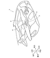
- FIG. 1 is an image diagram showing an arrangement example of an operation device 3 of an automatic transmission for a vehicle according to an embodiment of the present invention.
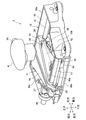
- FIG. 2 is a perspective view showing the structure of the operating device 3 according to the first embodiment of the present invention.
- 3 is a top view of the operating device 3
- FIG. 4 is a bottom view showing the internal structure of the operating device 3
- FIG. 5 is a rear view of the operating device 3
- FIG. 6 is a right side view of the operating device 3.
- FIG. 7 is a bottom view of the operating device 3 when the shift knob 4 is moved to the rear of the vehicle.
- the right front portion of the bottom wall 10b of the base bracket 10 (bracket), which will be described later, is partially opened. Further, in FIG. 7, the description of the shift knob 4, the bottom wall 10b, and the shift lock mechanism portion 50 is omitted.
- the operating device 3 of the first embodiment of the present invention includes a shift knob 4 operated by the driver of the vehicle 1 in order to select a shift position of the automatic transmission for the vehicle. ..
- the operation device 3 is arranged on the center console 2 whose upper surface is substantially horizontal on the side of the driver's seat 5 of the vehicle 1.
- the operating device 3 is fixed to the vehicle body inside the center console 2, and the shift knob 4 is arranged so as to project upward from the upper surface of the center console 2.
- the operating device 3 includes a base bracket 10, a slider lever 11 (slide portion), a main gear 12 (gear), a detent mechanism portion 13, and a shift lock mechanism portion 50.
- the base bracket 10 and the slider lever 11 are made of, for example, relatively high-strength aluminum.
- the base bracket 10 is a rectangular box-shaped member having an opening at the top and a thin vertical direction.
- the left side wall 10a of the base bracket 10 is located on the right side (inside) of the bottom wall 10b, the front side wall 10c, and the rear side wall 10d by about 1 to 2 cm, and the upper end is several mm from the upper ends of the front side wall 10c and the rear side wall 10d. Located below.
- a main shaft 15 that extends in the vertical direction intermediate portion of the internal space 14 of the base bracket 10 in the vertical direction along the right side wall 10e is provided.
- a sub-shaft extending in the vertical direction intermediate portion of the base bracket 10 in the front-rear direction along the left side wall 10a of the base bracket 10 in parallel with the main shaft 15. 17 (second shaft) is provided.
- the front ends of the main shaft 15 and the sub-shaft 17 are fixed to the front side wall 10c of the base bracket 10, and the rear ends of the main shaft 15 and the sub-shaft 17 are fixed to the rear side wall 10d of the base bracket 10.
- the slider lever 11 has a slide portion 20 which is a substantially isosceles triangular plate member with the right portion as the base, a first boss portion 21 into which the main shaft 15 is inserted, and a second boss into which the sub shaft 17 is inserted.
- the part 22 is provided.
- the first boss portion 21 is formed, for example, to have a length of approximately 1/2 of the length in the front-rear direction of the internal space 14 of the base bracket 10, and is arranged at the right end portion of the slide portion 20.
- the second boss portion 22 is arranged at the left end portion of the slide portion 20.
- the upper surface of the slide portion 20 is arranged slightly below the upper end of the base bracket 10. Therefore, the slide portion 20 of the slider lever 11 is arranged above the internal space 14 of the base bracket 10, the right portion is supported by the main shaft 15, and the left portion is left beyond the upper portion of the left side wall 10a of the base bracket 10. It extends in the direction and is supported by the sub-shaft 17, and is arranged so as to be movable in the front-rear direction along the main shaft 15 and the sub-shaft 17.
- a pin 23 extending upward is provided on the upper surface of the right portion of the slide portion 20, and the shift knob 4 is inserted and fixed to the pin 23.
- the right side of the shift knob 4 is provided with a push button 25 for releasing the lever lock and a select plate 26 having a built-in indicator lamp for displaying the selected shift position.
- a flexible substrate (wiring) 27 for inputting / outputting operation / display control signals to the push button 25 and the select plate 26 is provided on the upper surface of the slide portion 20.
- the flexible substrate 27 extends from the shift knob 4 to the left on the upper surface of the slide portion 20, projects rearward from the left end portion of the slide portion 20, and bends in front of the rear side wall 10d of the base bracket 10 to bend the left side wall 10a of the base bracket 10. It is connected to the outside via a printed circuit board 28 fixed to the outside of the.
- a rack gear 30 is provided on the left side surface of the first boss portion 21 of the slider lever 11. Further, the rear end portion of the first boss portion 21 is provided with a tubular plunger support portion 49 extending to the left from the first boss portion 21 and supporting the detent plunger 46 (plunger) described later. ..
- the plunger support portion 49 has a hole having a diameter of several mm that is open on the left side.
- the main gear 12 is a fan-shaped plate-shaped spur gear, and is arranged in the internal space 14 of the base bracket 10.
- the main gear 12 is rotatably supported by a gear support shaft 35 (rotary support shaft) whose central angle portion extends in the vertical direction.
- the gear support shaft 35 is provided so as to extend upward from the bottom wall 10b at a position close to the left side wall 10a in the front-rear direction intermediate portion of the internal space 14 of the base bracket 10.
- the main gear 12 is arranged adjacent to the lower surface of the lower surface of the slide portion 20, and has gear teeth 36 formed on the outer peripheral portion of the arc shape, and is configured as a pinion gear that meshes with the rack gear 30 of the slider lever 11.
- the gear teeth 36 of the main gear 12 and the rack gear 30 of the slider lever 11 are formed in a tapered shape in which the tooth surfaces are inclined in the left-right direction with respect to the up-down direction. Specifically, the upper part of the tooth surface is inclined so as to be located to the left of the lower part. Further, although the movement of the main gear 12 is restricted by the snap pin 37 inserted into the gear support shaft 35, the main gear 12 can move slightly in the vertical direction with respect to the gear support shaft 35.
- the main gear 12 is configured to be urged upward with respect to the base bracket 10 by a coil spring 38 (first urging portion) provided coaxially with the gear support shaft 35.
- a shift connected to the transmission of the vehicle 1 via a support pin 39 at a position separated from the insertion portion of the gear support shaft 35, that is, the support position of the main gear 12 in the radial direction of the main gear 12.
- the ends of the wires 40 are connected.
- the shift wire 40 extends forward from the connection point with the main gear 12, passes through a hole (not shown) provided in the front side wall 10c, and extends forward.
- the detent mechanism portion 13 is composed of a detent piece 45 provided on the base bracket 10, a detent plunger 46 supported by the slider lever 11, and a shift spring 47 (second urging portion).
- the detent piece 45 is fixed on the bottom wall 10b of the base bracket 10, extends the central portion of the internal space 14 of the base bracket 10 in the left-right direction in the front-rear direction in parallel with the main shaft 15, and has a rod shape having a substantially L-shaped cross section in the left-right direction. It is a member.
- a concave-convex surface 48 (concave-convex portion) is formed on the right side surface of the portion extending in the vertical direction of the detent piece 45.
- the detent plunger 46 is a rod-shaped pin that is inserted into the plunger support portion 49 provided on the slider lever 11.
- the shift spring 47 is, for example, a coiled spring inserted into the plunger support portion 49.
- the detent plunger 46 is pushed outward (to the left) by the shift spring 47, and the tip is arranged so as to abut on the uneven surface 48 which is the right inner side surface of the detent piece 45.
- the uneven surface 48 provided on the right inner side surface of the detent piece 45 is uneven in the left-right direction, and the pressing force by the detent plunger 46 changes according to the moving position of the slider lever 11 in the front-rear direction.
- the uneven surface 48 is formed so that the detent plunger 46 comes into contact with the concave portion at the front-rear position corresponding to each shift position of the slider lever 11 to obtain a click feeling.
- the shift position becomes parking (P) when the slider lever 11 moves to the frontmost position as shown in FIG. 3, and shifts when the slider lever 11 moves to the rearmost position as shown in FIG.
- the position becomes the drive (D).
- reverse (R) and neutral (N) can be selected in order from the front between the parking (P) and the drive (D).
- the shift lock mechanism unit 50 is composed of a shift lock stopper 51 and a shift lock solenoid 52.
- the shift lock stopper 51 is a key-shaped bracket, which is provided in the internal space 14 of the base bracket 10 and is arranged below the main gear 12.
- the front end of the shift lock stopper 51 is rotatably supported by the bottom wall 10b of the base bracket 10, extends rearward along the main shaft 15, and a left-bent key portion 51a is formed at the rear end. ing.
- the shift lock solenoid 52 is provided in the internal space 14 of the base bracket 10 and has a function of swinging the shift lock stopper 51.
- the key portion 51a of the shift lock stopper 51 is configured to move in the left-right direction by the shift lock solenoid 52.
- a recess 53 into which the key portion 51a is inserted is formed on the left side surface of the first boss portion 21 of the slider lever 11.
- the forward / backward movement of the slider lever 11 is restricted by inserting the key portion 51a of the shift lock stopper 51 into the recess 53.
- the shift lock solenoid 52 swings the shift lock stopper 51 to swing the key portion 51a to the left to separate it from the recess 53, whereby the slider lever 11 is allowed to move back and forth.
- the shift position can be locked and unlocked by the operation of the shift lock solenoid 52.
- the operating device 3 of the vehicle transmission includes a base bracket 10 fixed to the vehicle body of the vehicle 1, a slider lever 11 provided with a shift knob 4, and a transmission.
- the strength of the support structure of the slider lever 11 can be made relatively high.
- the slider lever 11 and the main gear 12 have a separate structure, for example, even if the driver of the vehicle 1 applies a force to the shift knob 4 in the left-right direction, it is difficult for a large force to act on the main gear 12. It has become. Therefore, the strength of the main gear 12 can be suppressed to reduce the thickness. As a result, the operation device 3 can be made compact while sufficiently ensuring the strength.
- the gear support shaft 35 which is the rotation shaft of the main gear 12, is a fan-shaped plate-shaped member arranged so as to extend in the vertical direction perpendicular to the slide direction of the slider lever 11, and the main gear 12 is connected to the slider lever 11. Since the base bracket 10 is arranged so as to extend in the left-right direction to the side of the first boss portion 21 which is the support portion of the above, the base bracket 10 can be made thinner in the vertical direction. As a result, when the operating device 3 is installed on the upper surface of the center console 2 of the vehicle 1 extending substantially horizontally, the installation space of the operating device 3 required downward from the upper surface of the center console 2 can be suppressed. Therefore, the vehicle mountability of the operating device 3 can be improved.
- the slide amount of the slider lever 11, that is, the slide of the shift knob 4 can be set by setting the connection point between the main gear 12 and the shift wire 40 at an appropriately changed position.
- the moving distance of the shift wire 40 with respect to the amount can be easily changed. This makes it possible to improve the applicability of the operating device 3 to various transmissions.
- the shift knob 11 since the slider lever 11 is supported not only by the main shaft 15 with respect to the base bracket 10 but also by the sub-shaft 17 arranged apart from the main shaft 15, the shift knob The load received by the slider lever 11 when a force is applied to 4 can be distributed and received by the main shaft 15 and the sub shaft 17. Therefore, it is possible to reduce the load applied to the first boss portion 21, the second boss portion 22, and the main shaft 15 and the sub shaft 17 which are support portions thereof when a force is particularly applied to the shift knob 4 in the left-right direction. can. By reducing the load acting on the parts such as the slider lever 11 and the base bracket 10 in this way, it is possible to reduce the thickness of these parts and reduce the weight and cost.
- the slider lever 11 is a flat plate in which the first boss portion 21 into which the main shaft 15 is inserted and the second boss portion 22 into which the sub shaft 17 is inserted are arranged so as to straddle the upper portion of the plate-shaped main gear 12. Since it is configured by being connected by the shaped slide portion 20, the vertical dimension of the base bracket 10 for accommodating the slider lever 11 and the main gear 12 can also be suppressed.
- the gear teeth 36 of the main gear 12 and the rack gear 30 are formed in a tapered shape with their tooth surfaces inclined from the vertical direction, and the main gear 12 is urged upward by the coil spring 38, and the gear teeth of the main gear 12 are formed. Since the 36 and the rack gear 30 are pressed against each other, backlash between the main gear 12 and the rack gear 30 can be reduced. As a result, rattling between the main gear 12 and the rack gear 30 can be suppressed, smooth operation of the main gear 12 can be achieved, accurate shift operation can be performed, and operability can be improved.
- the detent mechanism portion 13 is provided, and when the slider lever 11 is moved in the front-rear direction, the detent plunger 46 provided on the slider lever 11 is provided on the base bracket 10. Since it moves while being pressed against the uneven surface 48 of the detent piece 45, a click feeling can be obtained at each shift position. As a result, the position of the slider lever 11 can be easily adjusted to each shift position, and the operability of the shift operation can be improved. Further, since the detent plunger 46 is arranged in the internal space 14 of the base bracket 10 so as to extend in the left-right direction adjacent to the lower side of the main gear 12, the vertical dimension of the base bracket 10 can be suppressed.
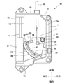
- FIG. 8 is a bottom view showing the internal structure of the operating device 60 according to the second embodiment of the present invention.
- FIG. 9 is a bottom view of the operating device 60 when the shift knob 4 is moved to the rear of the vehicle.
- the operation device 60 of the second embodiment has a different structure of the detent mechanism unit 61 that gives a click feeling when the slider lever 11 is moved with respect to the operation device 3 of the first embodiment.
- the parts different from the operation device 3 of the first embodiment will be described.
- the detent mechanism portion 61 in the operating device 60 of the second embodiment includes a detent piece 62 provided in the main gear 12, a detent plunger 63 (plunger) supported by the base bracket 10, and a shift spring 64 (with a second attachment). It is composed of a group) and.
- the detent piece 62 is fixed to the lower surface of the main gear 12 and is arranged closer to the gear support shaft 35 than the gear teeth 36 provided on the outer peripheral portion of the main gear 12.
- the detent piece 62 is formed in an arc shape centered on the gear support shaft 35, and has a substantially rectangular cross section in the radial direction.
- a concave-convex surface 65 (concave-convex portion) uneven in the radial direction is formed on the side surface of the detent piece 62 on the side surface of the arc-shaped gear support shaft 35.
- the detent plunger 63 and the shift spring 64 are supported by a cylindrical plunger support portion 66 fixed to the base bracket 10.
- the detent plunger 63 is pushed out in the radial direction (substantially to the right) of the main gear 12 by the shift spring 64, and the tip is arranged so as to abut on the uneven surface 65 of the detent piece 62.
- the detent mechanism unit 61 of the second embodiment changes the pressing force by the detent plunger 63 according to the rotation position of the main gear 12.
- the concave-convex surface 65 is formed so that the detent plunger 63 abuts on the concave portion of the concave-convex surface 65 at the front-rear position corresponding to each shift position of the slider lever 11 to obtain a click feeling.
- the reaction force of the pressing force by the detent plunger 46 acts on the slider lever 11 to the right, that is, the force is perpendicular to the slide direction of the slider lever 11. Acts on this, so that sliding resistance is generated when the slider lever 11 is moved in the front-rear direction.
- the detent plunger 63 is provided on the main gear 12, and the detent plunger 63 and the shift spring 64 are supported on the base bracket 10. Therefore, the detent plunger 63 is used.
- the main gear 12 that receives the pressing force is supported by the gear support shaft 35, and the reaction force of the pressing force by the detent plunger 63 is supported by the base bracket 10. Therefore, the pressing force by the detent plunger 63 and its reaction force do not directly act on the slider lever 11.
- the operating device 60 of the second embodiment the sliding resistance of the slider lever 11 can be suppressed as compared with the operating device 3 of the first embodiment, and the operability of the shift operation can be further improved.
- the backlash between the main gear 12 and the rack gear 30 is caused by pressing the main gear 12 substantially to the right, that is, toward the slider lever 11 by the detent plunger 63 in the detent mechanism unit 61. It can be reduced. As a result, the rattling of the main gear 12 and the rack gear 30 can be suppressed, the operating load (slide load) of the shift knob 4 can be reduced, and the rattling of the shift knob 4 can be suppressed.
- the slider lever 11 is urged in the direction away from the main gear 12 by pressing the detent plunger 46 in the detent mechanism unit 13. Therefore, the operating device 3 of the first embodiment has a larger operating load of the shift knob 4 than the operating device 60 of the second embodiment, and is suitable for an operating device that wants to be operated firmly (heavy) to some extent. Further, in the operating device 3 of the first embodiment, the rattling of the slider lever 11 can be suppressed by pressing the detent plunger 46 on the detent mechanism unit 13, and the rattling of the shift knob 4 can be suppressed.
- FIG. 10 is a bottom view showing the internal structure of the operating device 70 according to the third embodiment of the present invention. Note that FIG. 10 is a bottom view of the operating device 70 when the shift knob 4 in the operating device 70 is moved to the front of the vehicle, and the description of the bottom wall 10b is omitted.
- FIG. 11 is a vertical cross-sectional view of the first gear 71 in the operating device 70 near the gear support shaft 73. 11 is a cross-sectional view of the AA portion described in FIG. 10 (in FIG. 11, the upper side when fixed to the vehicle body is on the upper side on the paper surface, and the lower side is on the lower side on the paper surface. (Illustrated).
- the end of the shift wire 40 is connected to the main gear 12 via the support pin 39, but in the operating device 70 of the third embodiment, it is shown in FIG. As described above, the second gear 72 is interposed between the first gear 71 corresponding to the main gear 12 and the end of the shift wire 40.
- the first gear 71 is fan-shaped like the main gear 12, is rotatably supported by the base bracket 10 via a gear support shaft 73 extending in the vertical direction, and is a first gear that meshes with the rack gear 30 on the outer peripheral portion.
- the gear teeth 74 (first tooth surface) of the above are provided.
- the first gear 71 further includes a second gear tooth 75 (second tooth surface) arranged in the circumferential direction at a position different in the radial direction from the first gear tooth 74.
- the second gear 72 is arranged adjacent to the rear of the first gear 71, and is rotatably supported by the base bracket 10 via a gear support shaft 76 extending in the vertical direction.
- the gear support shaft 76 is arranged to the right rear of the gear support shaft 73 of the first gear 71.
- the second gear 72 has a third gear tooth 77 (third tooth surface) that meshes with the second gear tooth 75, and also includes an extension portion 78 that extends to the left from the support position of the gear support shaft 76. There is.
- the end of the shift wire 40 is supported at the tip of the extension 78 via a support pin 79.
- the support pin 79 is located to the left of the gear support shaft 73 of the first gear 71.
- two sets of gears (rack gear 30 and first gear teeth 74) are provided between the first boss portion 21 to which the shift knob 4 is fixed and the end portion of the shift wire 40.
- the second gear tooth 75 and the third gear tooth 77) are interposed. Therefore, by appropriately setting the reduction ratios of these two sets of gears, the moving distance of the end portion of the shift wire 40 in the front-rear direction (of the shift wire 40) with respect to the slide distance in the front-rear direction of the shift knob 4 (the amount of operation of the shift knob 4).
- the operating amount) and the operating load of the shift knob 4 can be set as appropriate.
- the shift wire while suppressing the operating load of the shift knob 4 to be small. It is possible to set the operation amount of the shift knob 4 to be small after securing the required amount of the operation amount of 40.
- the first gear 71 is urged downward with respect to the base bracket 10 by a coil spring 80 (first urging portion) coaxially provided with the gear support shaft 73. It is configured. Further, the second gear tooth 75 and the third gear tooth 77 have a tapered shape that is slightly inclined inward in the radial direction as the second gear tooth 75 and the third gear tooth 77 are directed downward.
- the detent mechanism portion 85 of the operating device 70 includes a detent piece 86 provided in the first gear 71, a detent plunger 63 (plunger) supported by the base bracket 10, and a shift spring 64 (with a second attachment). It is composed of the force section) and.
- the detent piece 86 is provided on the front side of the gear support shaft 73 of the first gear 71, and has, for example, a wall surface 87 formed in an arc shape centered on the gear support shaft 73 with a width of about 1 cm in the vertical direction. There is.
- the wall surface 87 is inclined outward in the radial direction as it goes downward.
- the detent plunger 63 and the shift spring 64 are supported by a cylindrical plunger support portion 66 fixed to the base bracket 10.
- the plunger support 66 It is located on the left front side of the gear support shaft 73, and is arranged so that the tip of the detent plunger 63 abuts on the wall surface 87 of the detent piece 86.
- the plunger support portion 66 is arranged with an inclined axis so that the detent plunger 63 is pushed out toward the gear support shaft 76 on the right rear side and diagonally upward by the shift spring 64.
- the rattling of the first gear 71 can be suppressed by pressing the first gear 71 against the gear support shaft 73 by the urging force of the detent plunger 63 in the detent mechanism portion 85. Further, the detent plunger 63 abuts on the inclined wall surface 87 to urge the first gear 71 downward. As a result, the inclined second gear tooth 75 and the third gear tooth 77 can be brought closer to each other to further reduce backlash.
- the first boss portion 21 is not urged by the detent mechanism portion 85, the sliding resistance of the first boss portion 21 during sliding can be suppressed and the operating force of the shift knob 4 can be reduced. .. Then, the coil spring 80 and the detent mechanism portion 85 can reduce the backlash between the second gear tooth 75 and the third gear tooth 77, suppress the rattling of the first gear 71, and the shift knob 4 The operability of the can be improved.
- the wall surface 87 of the detent piece 86 may be provided with a recess at a position where the tip of the detent plunger 63 abuts to give a click feeling when the shift knob 4 is slid, or the wall surface 87 may be flattened. A structure that gives a click feeling to other parts may be provided.
- the operation device 3 is installed on a substantially horizontal plane of the center console 2 of the vehicle 1, but the operation device 3 may be installed on the installation surface of the vehicle 1 facing in another direction.
- the installation space of the operation device 3 can be reduced in the direction toward the back side of the installation surface. can.
- the installation space of the operation device 3 in the left-right direction of the vehicle can be reduced.
- the shape of the main gear 12 may be a shape other than a fan shape such as a T-shape or an inverted L-shape.
- the present invention can be widely applied to an operating device for a transmission of various vehicles.
Landscapes
- Engineering & Computer Science (AREA)
- General Engineering & Computer Science (AREA)
- Mechanical Engineering (AREA)
- Chemical & Material Sciences (AREA)
- Combustion & Propulsion (AREA)
- Transportation (AREA)
- Arrangement Or Mounting Of Control Devices For Change-Speed Gearing (AREA)
- Gear-Shifting Mechanisms (AREA)
Priority Applications (4)
| Application Number | Priority Date | Filing Date | Title |
|---|---|---|---|
| US17/995,016 US12060932B2 (en) | 2020-04-01 | 2021-03-30 | Operation device for vehicle transmission and vehicle |
| CN202180026500.0A CN115379960A (zh) | 2020-04-01 | 2021-03-30 | 车辆用变速器的操作装置以及车辆 |
| JP2022512592A JP7339489B2 (ja) | 2020-04-01 | 2021-03-30 | 車両用変速機の操作装置及び車両 |
| KR1020227034505A KR102772018B1 (ko) | 2020-04-01 | 2021-03-30 | 차량용 변속기의 조작 장치 및 차량 |
Applications Claiming Priority (2)
| Application Number | Priority Date | Filing Date | Title |
|---|---|---|---|
| JP2020065986 | 2020-04-01 | ||
| JP2020-065986 | 2020-04-01 |
Publications (1)
| Publication Number | Publication Date |
|---|---|
| WO2021201045A1 true WO2021201045A1 (ja) | 2021-10-07 |
Family
ID=77930370
Family Applications (1)
| Application Number | Title | Priority Date | Filing Date |
|---|---|---|---|
| PCT/JP2021/013708 Ceased WO2021201045A1 (ja) | 2020-04-01 | 2021-03-30 | 車両用変速機の操作装置及び車両 |
Country Status (5)
| Country | Link |
|---|---|
| US (1) | US12060932B2 (https=) |
| JP (1) | JP7339489B2 (https=) |
| KR (1) | KR102772018B1 (https=) |
| CN (1) | CN115379960A (https=) |
| WO (1) | WO2021201045A1 (https=) |
Families Citing this family (1)
| Publication number | Priority date | Publication date | Assignee | Title |
|---|---|---|---|---|
| KR102520863B1 (ko) * | 2023-02-28 | 2023-04-12 | 이신영 | 기어 변속장치 |
Citations (3)
| Publication number | Priority date | Publication date | Assignee | Title |
|---|---|---|---|---|
| JPS6258227U (https=) * | 1985-09-30 | 1987-04-10 | ||
| JP2003285663A (ja) * | 2002-03-28 | 2003-10-07 | Fuji Kiko Co Ltd | 自動変速機におけるシフトレバーの操作ノブ構造 |
| JP2006044374A (ja) * | 2004-08-02 | 2006-02-16 | Honda Motor Co Ltd | シフト装置 |
Family Cites Families (10)
| Publication number | Priority date | Publication date | Assignee | Title |
|---|---|---|---|---|
| DE4305015C1 (de) * | 1993-02-18 | 1994-03-10 | Ford Werke Ag | Wählhebelanordnung für ein automatisches Getriebe eines Kraftfahrzeuges |
| JPH07224921A (ja) * | 1994-02-14 | 1995-08-22 | Niles Parts Co Ltd | 直線移動するシフトレバー装置 |
| JP3635852B2 (ja) * | 1997-04-15 | 2005-04-06 | 井関農機株式会社 | 苗移植機 |
| JP2005273818A (ja) * | 2004-03-25 | 2005-10-06 | Atsumi Tec:Kk | 車両用自動変速操作装置 |
| JP2005271789A (ja) | 2004-03-25 | 2005-10-06 | Atsumi Tec:Kk | 車両用自動変速操作装置 |
| US7467569B2 (en) * | 2007-01-04 | 2008-12-23 | Dura Global Technologies, Inc. | Detent plunger for automatic transmission shifter |
| KR101299251B1 (ko) | 2008-10-21 | 2013-08-22 | 삼성테크윈 주식회사 | 렌즈 이동 장치 |
| DE102010028624A1 (de) * | 2010-05-05 | 2011-11-10 | Zf Friedrichshafen Ag | Translatorische Betätigungseinrichtung mit mittelbarer Rastierung |
| DE102010030808A1 (de) * | 2010-06-04 | 2011-12-08 | Zf Friedrichshafen Ag | Mechanische Parksperrenbetätigung mit Richtungsumkehr und variabler Übersetzung |
| KR101183840B1 (ko) * | 2012-02-22 | 2012-09-19 | 주식회사 인팩 | 자동변속차량용 변속케이블의 변속레버 동작검출장치 |
-
2021
- 2021-03-30 JP JP2022512592A patent/JP7339489B2/ja active Active
- 2021-03-30 US US17/995,016 patent/US12060932B2/en active Active
- 2021-03-30 WO PCT/JP2021/013708 patent/WO2021201045A1/ja not_active Ceased
- 2021-03-30 CN CN202180026500.0A patent/CN115379960A/zh active Pending
- 2021-03-30 KR KR1020227034505A patent/KR102772018B1/ko active Active
Patent Citations (3)
| Publication number | Priority date | Publication date | Assignee | Title |
|---|---|---|---|---|
| JPS6258227U (https=) * | 1985-09-30 | 1987-04-10 | ||
| JP2003285663A (ja) * | 2002-03-28 | 2003-10-07 | Fuji Kiko Co Ltd | 自動変速機におけるシフトレバーの操作ノブ構造 |
| JP2006044374A (ja) * | 2004-08-02 | 2006-02-16 | Honda Motor Co Ltd | シフト装置 |
Also Published As
| Publication number | Publication date |
|---|---|
| CN115379960A (zh) | 2022-11-22 |
| US12060932B2 (en) | 2024-08-13 |
| KR102772018B1 (ko) | 2025-02-26 |
| JPWO2021201045A1 (https=) | 2021-10-07 |
| US20230213094A1 (en) | 2023-07-06 |
| KR20220151186A (ko) | 2022-11-14 |
| JP7339489B2 (ja) | 2023-09-06 |
Similar Documents
| Publication | Publication Date | Title |
|---|---|---|
| CN102884346B (zh) | 带有间接锁止装置的平移式操纵装置 | |
| US10077004B2 (en) | Multi-link knob type armrest and armrest console and vehicle using the same | |
| EP1666772A1 (en) | Vehicular automatic transmission and selector lever thereof | |
| WO2021201045A1 (ja) | 車両用変速機の操作装置及び車両 | |
| US20080100086A1 (en) | Instrument panel assembly for a vehicle | |
| US20180087659A1 (en) | Lever apparatus for electronic shift system | |
| JPH09323559A (ja) | 自動変速機の操作装置 | |
| EP1580460A2 (en) | A selector apparatus of an automatic transmission of vehicle | |
| KR100306253B1 (ko) | 자동트랜스미션용작동장치 | |
| US20050217404A1 (en) | Selector apparatus of an automatic transmission of vehicle | |
| JP5547025B2 (ja) | シフト装置 | |
| JP2005297756A (ja) | 自動変速機用シフトレバー装置 | |
| WO2019207914A1 (ja) | シフト装置 | |
| JP2024011082A (ja) | シフト装置 | |
| JP4445241B2 (ja) | シフトレバー装置 | |
| EP1920966A1 (en) | Instrument panel assembly for a vehicle | |
| JP7839590B2 (ja) | レバー入力装置 | |
| JP3475711B2 (ja) | 手動変速機の操作装置 | |
| JPH10157480A (ja) | 自動変速機用操作装置 | |
| JP3595919B2 (ja) | キーインタロックケーブルの配索構造 | |
| JP2005271789A (ja) | 車両用自動変速操作装置 | |
| US20240035561A1 (en) | Shift device | |
| JPH115454A (ja) | 変速機のシフトレバー装置 | |
| JP6316634B2 (ja) | 自動変速機用シフトレバー装置 | |
| JP2001180324A (ja) | コラム式変速操作装置 |
Legal Events
| Date | Code | Title | Description |
|---|---|---|---|
| 121 | Ep: the epo has been informed by wipo that ep was designated in this application |
Ref document number: 21781300 Country of ref document: EP Kind code of ref document: A1 |
|
| ENP | Entry into the national phase |
Ref document number: 2022512592 Country of ref document: JP Kind code of ref document: A |
|
| ENP | Entry into the national phase |
Ref document number: 20227034505 Country of ref document: KR Kind code of ref document: A |
|
| NENP | Non-entry into the national phase |
Ref country code: DE |
|
| 122 | Ep: pct application non-entry in european phase |
Ref document number: 21781300 Country of ref document: EP Kind code of ref document: A1 |