WO2021199399A1 - Machine électrique rotative - Google Patents
Machine électrique rotative Download PDFInfo
- Publication number
- WO2021199399A1 WO2021199399A1 PCT/JP2020/015169 JP2020015169W WO2021199399A1 WO 2021199399 A1 WO2021199399 A1 WO 2021199399A1 JP 2020015169 W JP2020015169 W JP 2020015169W WO 2021199399 A1 WO2021199399 A1 WO 2021199399A1
- Authority
- WO
- WIPO (PCT)
- Prior art keywords
- stator
- frame
- annular member
- electric machine
- rotary electric
- Prior art date
Links
Images


Classifications
-
- H—ELECTRICITY
- H02—GENERATION; CONVERSION OR DISTRIBUTION OF ELECTRIC POWER
- H02K—DYNAMO-ELECTRIC MACHINES
- H02K5/00—Casings; Enclosures; Supports
- H02K5/04—Casings or enclosures characterised by the shape, form or construction thereof
- H02K5/10—Casings or enclosures characterised by the shape, form or construction thereof with arrangements for protection from ingress, e.g. water or fingers
-
- H—ELECTRICITY
- H02—GENERATION; CONVERSION OR DISTRIBUTION OF ELECTRIC POWER
- H02K—DYNAMO-ELECTRIC MACHINES
- H02K1/00—Details of the magnetic circuit
- H02K1/06—Details of the magnetic circuit characterised by the shape, form or construction
- H02K1/12—Stationary parts of the magnetic circuit
-
- H—ELECTRICITY
- H02—GENERATION; CONVERSION OR DISTRIBUTION OF ELECTRIC POWER
- H02K—DYNAMO-ELECTRIC MACHINES
- H02K1/00—Details of the magnetic circuit
- H02K1/06—Details of the magnetic circuit characterised by the shape, form or construction
- H02K1/12—Stationary parts of the magnetic circuit
- H02K1/18—Means for mounting or fastening magnetic stationary parts on to, or to, the stator structures
- H02K1/185—Means for mounting or fastening magnetic stationary parts on to, or to, the stator structures to outer stators
-
- H—ELECTRICITY
- H02—GENERATION; CONVERSION OR DISTRIBUTION OF ELECTRIC POWER
- H02K—DYNAMO-ELECTRIC MACHINES
- H02K15/00—Methods or apparatus specially adapted for manufacturing, assembling, maintaining or repairing of dynamo-electric machines
- H02K15/02—Methods or apparatus specially adapted for manufacturing, assembling, maintaining or repairing of dynamo-electric machines of stator or rotor bodies
-
- H—ELECTRICITY
- H02—GENERATION; CONVERSION OR DISTRIBUTION OF ELECTRIC POWER
- H02K—DYNAMO-ELECTRIC MACHINES
- H02K2213/00—Specific aspects, not otherwise provided for and not covered by codes H02K2201/00 - H02K2211/00
- H02K2213/03—Machines characterised by numerical values, ranges, mathematical expressions or similar information
Definitions
- This application relates to a rotary electric machine.
- Patent Document 1 JP 2016-136829
- the contact surface of the stator with the frame has a step due to the laminating.
- the frame made of an aluminum-based material having low hardness is scraped, and there is a problem that shavings of the frame are scattered inside the rotary electric machine or the frame is damaged.
- the present application discloses a technique made in view of the above circumstances, and an object of the present application is to prevent foreign substances generated in the manufacturing process of a rotating electric machine such as shavings of a frame from being scattered inside the rotating electric machine. And.
- the rotor electric machine disclosed in the present application has a rotor shaft supported by a bearing, a rotor attached to the rotor shaft and rotating together with the rotor shaft, and a gap between the rotor so that the rotor can rotate.
- a rotor shaft supported by a bearing, a rotor attached to the rotor shaft and rotating together with the rotor shaft, and the rotor are voided so as to allow the rotation of the rotor.
- the cross section of the annular member is hatched. It is an enlarged view of the part A in FIG. It is a perspective view of the annular member exemplified in FIG. 1 and FIG. 1 is an explanatory view of an assembly process when the stator is assembled to the frame in the rotary electric machine illustrated in FIGS. 1 to 3, and the cross section is displayed by hatching. It is a perspective view which shows the other example of the annular member of the rotary electric machine which concerns on Embodiment 1 of this application. In the cross-sectional view of the rotary electric machine according to the second embodiment of the present application, the cross section of the annular member is hatched.
- FIG. 5 It is an enlarged view of the part A in FIG. 5 is an explanatory view of an assembly process when the stator is assembled to the frame in the rotary electric machine illustrated in FIGS. 5 to 7, and the cross section is displayed by hatching.
- the cross section of the annular member In the cross-sectional view of the rotary electric machine according to the third embodiment of the present application, the cross section of the annular member is hatched.
- FIG. 9 and 10 are explanatory views of an assembly process when the stator is assembled to the frame in the rotary electric machine illustrated, and the cross section is displayed by hatching.
- 9 is a perspective view of the annular member illustrated in FIGS. 9 and 10.
- FIG. 13 is an explanatory view of an assembly process when the stator is assembled to the frame in the rotary electric machine illustrated in FIGS. 13 and 14, and the cross section is displayed by hatching.
- Embodiment 1 Embodiment 1
- the rotary electric machine according to the present application is not limited to the following description, and can be appropriately changed without departing from the gist of the present application.
- the scale of each member may differ from the actual scale for ease of understanding, and the illustration of a configuration not related to the features of the present application is omitted.
- FIG. 1 is a cross-sectional view for explaining the configuration of a rotary electric machine
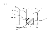
- FIG. 2 is an enlarged view of part A in FIG.
- the frame 2 which is the housing of the rotary electric machine 1 has a substantially cylindrical shape having an opening on the rear side (upper side of the drawing), and is made of an inexpensive and lightweight aluminum alloy.
- the stator 3 is formed by laminating electromagnetic steel sheets, and the stator winding 5 is wound via an insulator 4 which is an insulator, and terminals 6 and terminals 6 for supplying an electric current to the stator winding 5 are provided.
- a holder 7 for fixing is installed.
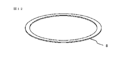
- the annular member 8 is an annular member, and a perspective view is shown in FIG.
- the annular member 8 is made of polyacetal resin, fluororesin, etc., which has a lower hardness than the aluminum alloy which is the material of the frame 2 and has excellent wear resistance, and has a chamfered portion 8a at the upper and lower edges on the outer peripheral side of the square cross section. It has a ring shape with 8b, and the outer diameter 8c is set to be larger than the hole diameter 2a of the frame 2 like the outer diameter 3a of the stator 3.
- the annular member 8 and the stator 3 are press-fitted in the order of the annular member 8 and the stator 3 from the opening on the rear side of the frame 2, and the annular member 8 and the stator 3 come into contact with each other. Will be installed.
- a bearing 9 is fixed to the frame 2 from the front side via a bearing holder 10 made of carbon steel from the rear side.
- a rotor 14 on which a magnet 13 is installed is fixed to the rotor shaft 12, and the rotor shaft 12 is rotatably supported by a bearing 9 and a bearing 11.
- the rotor 14 is arranged so as to be separated from the stator 3 and surrounded by the rotor 14. Further, a boss 15 for assembling with the vehicle side is installed at the end of the rotor shaft 12 in the front direction, and a rotation angle for detecting the rotational state of the rotor 14 is provided at the omitted portion of the rotor shaft 12 in the rear direction.
- a detection sensor is installed.
- reference numeral 16 denotes a heat sink in which a control device (not shown) is installed, and this heat sink 16 is fixed to the rear opening of the frame 2.
- the control device includes a power conversion circuit and a control circuit having a power semiconductor that converts a direct current from the outside, and a required current is supplied to the stator winding 5 via the terminal 6. As a result, a rotational force is generated in the rotor 14, and the rotor shaft 12 and the boss 15 are rotated.
- the annular member 8 and the stator 3 are set in the rear opening of the frame 2, and by applying a load to the stator 3, they are guided to the chamfered portion 8a of the annular member 8 and the press-fitting introduction taper 2b of the frame 2, and are annular.
- the member 8 is press-fitted into the frame 2. Since the annular member 8 has a hardness lower than that of the frame 2, is flexible and has excellent wear resistance, the frame 2 is not scraped during the press-fitting process.
- the edge portion 3b on the press-fitting tip side of the stator 3 is guided by the press-fitting introduction taper 2b of the frame 2, and then hits the press-fitting introduction portion edge 2c, so that the stress is locally excessive, and thread burr-like shavings, That is, foreign matter generated in the manufacturing process of the rotary electric machine is generated and adheres to the edge portion 3b of the stator 3, or falls off into the space 17 surrounded by the chamfered portion 8b of the annular member 8, the stator 3, and the frame 2. Or something.
- the contact surface with the frame 2 has a step due to the laminating, and the frame is made of an aluminum-based material having low hardness even during press fitting. 2 is scraped and adheres to the edge portion 3b of the stator 3, or falls off into the space 17 surrounded by the chamfered portion 8b of the annular member 8, the stator 3, and the frame 2. These shavings do not come out of the enclosed space 17 even if vibration, impact, or the like is applied.
- the shavings move in the frame 2 due to vibration, impact, or the like. If it gets between the stator 3 and the rotor 14 or in the bearings 9 and 11, normal rotation operation is hindered. Further, since the shavings, which are aluminum-based materials, have conductivity, there is a risk of short-circuiting if they adhere between conductive portions such as terminals 6. In the configuration of this embodiment, when the stator 3 is press-fitted into the frame 2, the shavings of the frame 2 are not scattered in the frame 2, and a highly reliable rotary electric machine can be provided.
- the annular member 8 may be made of a porous resin such as a fluorine-based sponge, and the annular member 8 may be impregnated with a lubricant such as mineral oil or liquid paraffin.
- a lubricant such as mineral oil or liquid paraffin.
- the annular member 8 has a quadrangular cross section and has a ring shape having chamfered portions 8a and 8b at the upper and lower edge portions on the outer peripheral side.
- the cross-sectional shape may be another shape as long as it is annular, such as one having a circular ring-shaped cross section.
- the above-mentioned thread burr-like shavings that is, foreign matter generated in the manufacturing process of the rotary electric machine, is held in the annular space 17 extending over the entire inner circumference of the frame 2, and the foreign matter is present. Moves from the region of space 17 to a region other than the region of space 17, for example, a gap 314 g between the stator 3 and the rotor 14, the coil end portion of the stator 3, bearings 9, 11 and the like. Is prevented.
- Embodiment 2 The rotary electric machine according to the second embodiment of the present application will be described with reference to FIGS. 6 to 8. Similar to the first embodiment, this embodiment also shows an example applied to the electric power steering mounted on the vehicle.
- FIG. 6 is a cross-sectional view for explaining the configuration of the rotary electric machine according to the second embodiment
- FIG. 7 is an enlarged view of part A of FIG.
- FIG. 8 is a diagram illustrating a press-fitting process.
- the annular member 8 and the stator 3 are formed as separate bodies, and are set and press-fitted into the rear opening of the frame 2, respectively.
- the stator 3 and the annular member 8 are integrated. It is configured to be press-fitted.
- the stator 3 is formed by laminating electromagnetic steel plates, and the press-fitting tip side has a small diameter portion 3c smaller than the outer diameter 3a, and the small diameter portion 3c has a hardness lower than that of the aluminum alloy which is the material of the frame 2.
- An annular member 8 made of a polyacetal resin, a fluororesin, or the like having excellent wear resistance is fixed or outsert molded.
- the outer diameter 8c of the annular member 8 is set to be larger than the hole diameter 2a of the frame 2 like the outer diameter 3a of the stator 3, and is press-fitted into the frame 2 together with the stator 3.
- Other configurations and operations are the same as those in the first embodiment.
- the annular member 8 is integrated with the stator 3, the workability of press fitting is good. Further, even when the annular member 8 is made of a porous resin such as a fluorine-based sponge and the annular member 8 is impregnated with a lubricant such as mineral oil or liquid paraffin as in the first embodiment, the annular member 8 is not touched. Since the lubricant can be impregnated and press-fitted, the work environment is not polluted and the work efficiency is improved.
- Embodiment 3 The rotary electric machine according to the third embodiment of the present application will be described with reference to FIGS. 9 to 12. Similar to the first and second embodiments, this embodiment also shows an example applied to the electric power steering mounted on the vehicle. 9 is a cross-sectional view for explaining the configuration of the rotary electric machine according to the third embodiment, and FIG. 10 is an enlarged view of part A of FIG. FIG. 11 is a diagram illustrating a press-fitting process.
- the annular member 8 has a rectangular cross section and a sheet shape as shown in the perspective view of FIG. 12, and is arranged on the frame 2.
- the annular member 8 does not necessarily have to be press-fitted into the frame 2.
- the annular member 8 may be outsert-molded on the frame 2. In this state, the stator 3 is press-fitted so as to come into contact with the annular member 8.
- the annular member 8 By using the annular member 8 as a material that is more flexible and elastic than an aluminum alloy such as resin, the annular member 8 can be brought into close contact with the stator 3 without a gap.
- the annular member 8 By forming the annular member 8 with a material having a Young's modulus lower than that of the aluminum alloy which is the material of the frame 2, In this case, the shavings adhering to the edge portion 3b of the stator 3 and the shavings dropped on the annular member 8 are sandwiched between the contact portions between the annular member 8 and the stator 3 when the press-fitting of the stator 3 is completed. Therefore, even if vibration, impact, etc. are applied, it will not be scattered in the frame 2.
- the shavings that have fallen off during the press-fitting process do not stick to the adhesive portion of the annular member 8 and do not move, so that the shavings do not move. Can be more reliably prevented from being scattered in the frame 2.
- Embodiment 4 Although the configurations in which the stator 3 formed by laminating the electromagnetic steel plates are directly press-fitted into the frame 2 have been described above in the first to third embodiments, the fourth embodiment of the present application illustrated in FIGS. 13 to 15 has been described. As described above, the stator 3 may be applied to a stator 3 which is press-fitted and fixed to a thin-walled cylindrical member 18 formed of carbon steel or the like.
- FIG. 14 is an enlarged view of part A in FIG. 13, and FIG. 15 is a diagram illustrating a press-fitting process. As is clear from FIGS.
- the press-fitting surface in contact with the frame 2 has no step formed by laminating the electromagnetic steel sheets of the stator 3, so that the press-fitting is performed. It is possible to suppress scraping of the frame 2 and provide a more reliable rotary electric machine.
- the first to fourth embodiments of the present application generally have the following features.
- Feature 1 A rotor shaft supported by a bearing, a rotor attached to the rotor shaft and rotating together with the rotor shaft, and the rotor surrounded by a gap 314 g so that the rotor can rotate.
- the stator, the rotor, and the frame surrounding the rotor and having the outer circumference of the stator attached to the inner circumference, and the entire circumference of the outer circumference extending over the entire inner circumference of the frame.
- stator is arranged on the front side of the child, the stator is formed of an electromagnetic laminated steel plate, the stator is press-fitted into the frame in the extending direction of the rotor shaft, and the annular member is the stator. It is arranged so as to be located in front of the press-fitting portion 3p in the direction of the press-fitting.
- the rotor shaft, the rotor fixed to the rotor shaft, the stator formed by laminating an electromagnetic laminated steel plate and arranged so as to surround the rotor, and the stator were wound around the stator.
- It is a rotary electric machine including a stator winding, a frame for press-fitting and holding the stator, and an annular member arranged in contact with the front of the press-fitting portion 3p of the stator in the press-fitting direction. Therefore, it is possible to prevent the shavings of the frame from being scattered inside the rotary electric machine, and it is possible to prevent the shavings from hindering the rotation and short-circuiting the energization of the stator winding.
- Feature 2 Since the annular member is press-fitted into the frame, it is possible to prevent the shavings of the frame from being scattered inside the rotary electric machine, the rotation is hindered by the shavings, and the stator winding is energized. Can be prevented from being short-circuited. In addition, the cost of shrink fitting can be eliminated.
- Feature 3 Since a space surrounded by the annular member, the stator, and the frame is formed, it is possible to more reliably prevent the shavings of the frame from being scattered inside the rotating electric machine, and the shavings rotate. Can be prevented from being hindered or short-circuiting the energization of the stator winding.
- Feature 4 The annular member is fixed to the stator, and the annular member is integrated with the stator, so that press-fitting workability is good.
- Feature 5 Since the annular member is made of a material having a hardness lower than that of the frame, it is possible to prevent the shavings of the frame from being scattered inside the rotating electric machine, and the shavings hinder the rotation or the stator winding. It is possible to prevent short-circuiting the energization to.
- Feature 6 Since the annular member is impregnated with a lubricant, the lubricant impregnated in the annular member is uniformly applied to the press-fitting surface of the frame and the stator, making it difficult to wear and generating shavings. It can be suppressed.
- Feature 7 Since the annular member is arranged on the frame and the annular member is fixed to the frame, the shavings are sandwiched between the contact portion between the annular member and the stator when the press-fitting of the stator is completed. Therefore, even if vibration or shock is applied, it will not be scattered in the frame.
- the annular member is made of a material having a Young's modulus lower than that of the frame, the annular member is made of a material that is more flexible and elastic than an aluminum alloy such as resin, so that the annular member adheres tightly to the stator.
- the shavings are sandwiched between the contact portion between the annular member and the stator, and are not scattered in the frame even if vibration or impact is applied.
- Feature 9 Since a part or the whole of the annular member has adhesiveness, in other words, at least a part of the annular member has the annular member adhered to at least one of the stator and the frame. By making the annular member sticky, the shavings that have fallen off during the press-fitting process do not stick and move, and the press-fitting of the stator is completed for the shavings. At this point, it is sandwiched between the contact portion between the annular member and the stator, and even if vibration, impact, etc. are applied, it does not scatter in the frame.
- Feature 10 Since the stator is held around by a thin-walled cylindrical member, in other words, the outer circumference of the stator is covered with a cylindrical member, and the stator is interposed via the cylindrical member. Since it is attached to the frame, the press-fitting surface that comes into contact with the frame eliminates the step formed by laminating the electromagnetic steel plates of the stator, which suppresses the frame from being scraped by press-fitting and makes rotation more reliable. Can provide electrical equipment.
- Feature 11 A rotor shaft supported by a bearing, a rotor attached to the rotor shaft and rotating together with the rotor shaft, and surrounding the rotor through a gap so that the rotor can rotate.
- a frame that surrounds the stator, the rotor, and the stator and has the outer circumference of the stator attached to the inner circumference, and is arranged so that the outer circumference extends over the entire circumference of the inner circumference of the frame. It is a rotary electric machine provided with an annular member that prevents residual foreign matter remaining at the boundary portion between the frame and the stator from moving to a region different from the boundary portion, and is generated in the manufacturing process and fixed to the frame.
- Residual foreign matter such as frame shavings remaining at the boundary portion with the child is in a region different from the boundary portion, for example, between the coil end portion of the stator winding, the bearing, the rotor and the stator. It moves to a region such as a gap during the process of manufacturing a rotary electric machine including the process of assembling the rotary electric machine, the process of assembling the rotary electric machine to a vehicle including a two-wheeled vehicle, or during the vibration of the rotary electric machine while the vehicle is in operation. It is possible to prevent unfavorable effects on the coil end portion, the bearing, the gap, and the like.
- each figure the same sign indicates the same or corresponding part.
- each embodiment can be modified, omitted, or combined as appropriate.
- the present application describes various exemplary embodiments and examples, the various features, embodiments, and functions described in one or more embodiments are specific embodiments. It is not limited to the application of, but can be applied to the embodiment alone or in various combinations. Therefore, innumerable variations not illustrated are envisioned within the scope of the techniques disclosed in the present application. For example, it is assumed that at least one component is modified, added or omitted, and further, at least one component is extracted and combined with the components of other embodiments.
Abstract
La présente invention concerne une machine électrique rotative qui comprend : un arbre de rotor (12) supporté par des paliers (9), (11) ; un rotor (14) qui est fixé à l'arbre de rotor (12) et tourne avec l'arbre de rotor (12) ; un stator (3) qui entoure le rotor (14) avec un espace (314g) entre eux de manière à pouvoir faire tourner le rotor (14) ; un cadre (2) qui entoure le rotor (14) et le stator (3), et a la circonférence externe du stator (3) fixée à la circonférence interne de celui-ci ; et un élément annulaire qui est disposé le long de la circonférence interne du cadre (2) et empêche des matières étrangères dans une partie limite entre le cadre (2) et le stator (3) de se déplacer vers une région différente de cette partie limite, des matières étrangères, telles que des copeaux du cadre, produites dans le processus de fabrication de machine électrique rotative étant empêchées d'être dispersées à l'intérieur de la machine électrique rotative.
Priority Applications (5)
| Application Number | Priority Date | Filing Date | Title |
|---|---|---|---|
| US17/800,408 US20230099339A1 (en) | 2020-04-02 | 2020-04-02 | Rotating electrical machine |
| CN202080098825.5A CN115336145A (zh) | 2020-04-02 | 2020-04-02 | 旋转电机 |
| JP2022511459A JP7466628B2 (ja) | 2020-04-02 | 2020-04-02 | 回転電機 |
| PCT/JP2020/015169 WO2021199399A1 (fr) | 2020-04-02 | 2020-04-02 | Machine électrique rotative |
| EP20928760.6A EP4131738A4 (fr) | 2020-04-02 | 2020-04-02 | Machine électrique rotative |
Applications Claiming Priority (1)
| Application Number | Priority Date | Filing Date | Title |
|---|---|---|---|
| PCT/JP2020/015169 WO2021199399A1 (fr) | 2020-04-02 | 2020-04-02 | Machine électrique rotative |
Publications (1)
| Publication Number | Publication Date |
|---|---|
| WO2021199399A1 true WO2021199399A1 (fr) | 2021-10-07 |
Family
ID=77927510
Family Applications (1)
| Application Number | Title | Priority Date | Filing Date |
|---|---|---|---|
| PCT/JP2020/015169 WO2021199399A1 (fr) | 2020-04-02 | 2020-04-02 | Machine électrique rotative |
Country Status (5)
| Country | Link |
|---|---|
| US (1) | US20230099339A1 (fr) |
| EP (1) | EP4131738A4 (fr) |
| JP (1) | JP7466628B2 (fr) |
| CN (1) | CN115336145A (fr) |
| WO (1) | WO2021199399A1 (fr) |
Citations (5)
| Publication number | Priority date | Publication date | Assignee | Title |
|---|---|---|---|---|
| JPH0458062U (fr) * | 1990-09-26 | 1992-05-19 | ||
| JP2004309334A (ja) * | 2003-04-08 | 2004-11-04 | Denso Corp | 圧力センサ装置 |
| WO2016076166A1 (fr) * | 2014-11-11 | 2016-05-19 | 株式会社ミツバ | Moteur d'essuie-glace sans balai |
| JP2016136829A (ja) | 2015-01-14 | 2016-07-28 | 株式会社ジェイテクト | モータユニット |
| JP2020054197A (ja) * | 2018-09-28 | 2020-04-02 | 日本電産サーボ株式会社 | モータ装置 |
Family Cites Families (3)
| Publication number | Priority date | Publication date | Assignee | Title |
|---|---|---|---|---|
| JP6318056B2 (ja) * | 2014-09-05 | 2018-04-25 | 日立オートモティブシステムズ株式会社 | 回転電機のハウジング、およびこれを備えた回転電機 |
| JP2018074685A (ja) * | 2016-10-26 | 2018-05-10 | マブチモーター株式会社 | ブラシレスモータ |
| DE102016222614A1 (de) * | 2016-11-17 | 2018-05-17 | Robert Bosch Gmbh | Stator einer elektrischen Maschine, eine elektrische Maschine, sowie Verfahren zum Herstellen einer solchen |
-
2020
- 2020-04-02 US US17/800,408 patent/US20230099339A1/en active Pending
- 2020-04-02 JP JP2022511459A patent/JP7466628B2/ja active Active
- 2020-04-02 CN CN202080098825.5A patent/CN115336145A/zh active Pending
- 2020-04-02 EP EP20928760.6A patent/EP4131738A4/fr active Pending
- 2020-04-02 WO PCT/JP2020/015169 patent/WO2021199399A1/fr unknown
Patent Citations (5)
| Publication number | Priority date | Publication date | Assignee | Title |
|---|---|---|---|---|
| JPH0458062U (fr) * | 1990-09-26 | 1992-05-19 | ||
| JP2004309334A (ja) * | 2003-04-08 | 2004-11-04 | Denso Corp | 圧力センサ装置 |
| WO2016076166A1 (fr) * | 2014-11-11 | 2016-05-19 | 株式会社ミツバ | Moteur d'essuie-glace sans balai |
| JP2016136829A (ja) | 2015-01-14 | 2016-07-28 | 株式会社ジェイテクト | モータユニット |
| JP2020054197A (ja) * | 2018-09-28 | 2020-04-02 | 日本電産サーボ株式会社 | モータ装置 |
Non-Patent Citations (1)
| Title |
|---|
| See also references of EP4131738A4 |
Also Published As
| Publication number | Publication date |
|---|---|
| JPWO2021199399A1 (fr) | 2021-10-07 |
| EP4131738A4 (fr) | 2023-05-24 |
| US20230099339A1 (en) | 2023-03-30 |
| JP7466628B2 (ja) | 2024-04-12 |
| EP4131738A1 (fr) | 2023-02-08 |
| CN115336145A (zh) | 2022-11-11 |
Similar Documents
| Publication | Publication Date | Title |
|---|---|---|
| JP5488614B2 (ja) | ステータコアの固定構造およびそれを備えた回転電機 | |
| JP5894030B2 (ja) | モータ | |
| CN209767318U (zh) | 电动致动器 | |
| US6940193B2 (en) | Spindle motor with an electro-conductive connection between the bearing system and the baseplate or flange | |
| JP2007135342A (ja) | 回転電機 | |
| WO2008068910A1 (fr) | Moteur de scanner à miroir polygonal et son procédé de fabrication | |
| WO2021199399A1 (fr) | Machine électrique rotative | |
| WO2019155541A1 (fr) | Machine électrique rotative intégrée à un dispositif de commande | |
| WO2014061156A1 (fr) | Moteur électrique et procédé de fabrication | |
| JP2010041884A (ja) | 車両用回転電機 | |
| US8975797B2 (en) | Disk-rotating motor and disk-driving device | |
| WO2016079819A1 (fr) | Machine électrique tournante et dispositif intégré à une machine électrique tournante | |
| KR102405080B1 (ko) | 하모닉 드라이브를 포함하는 로봇 구동계 시스템 | |
| JP2008283750A (ja) | 油圧ダンパ用モータ | |
| WO2017122289A1 (fr) | Machine électrique tournante et dispositif vibrant | |
| JP2012231564A (ja) | モータ | |
| JP2004340183A (ja) | 流体軸受装置 | |
| CN215596312U (zh) | 电动致动器 | |
| JP2020045985A (ja) | 電動アクチュエータ | |
| WO2021171556A1 (fr) | Moteur électrique, ventilateur et climatiseur | |
| JP4309222B2 (ja) | モータ及びパワーステアリング装置 | |
| JP6762610B2 (ja) | ブラシレスモータ | |
| JP2022116858A (ja) | 電動アクチュエータ、および電動アクチュエータの製造方法 | |
| JP2023082275A (ja) | 軸受の固定方法及び構造 | |
| JP2004180448A (ja) | 流体軸受スピンドルモータ |
Legal Events
| Date | Code | Title | Description |
|---|---|---|---|
| 121 | Ep: the epo has been informed by wipo that ep was designated in this application |
Ref document number: 20928760 Country of ref document: EP Kind code of ref document: A1 |
|
| ENP | Entry into the national phase |
Ref document number: 2022511459 Country of ref document: JP Kind code of ref document: A |
|
| NENP | Non-entry into the national phase |
Ref country code: DE |
|
| ENP | Entry into the national phase |
Ref document number: 2020928760 Country of ref document: EP Effective date: 20221102 |