WO2021199399A1 - Rotary electrical machine - Google Patents
Rotary electrical machine Download PDFInfo
- Publication number
- WO2021199399A1 WO2021199399A1 PCT/JP2020/015169 JP2020015169W WO2021199399A1 WO 2021199399 A1 WO2021199399 A1 WO 2021199399A1 JP 2020015169 W JP2020015169 W JP 2020015169W WO 2021199399 A1 WO2021199399 A1 WO 2021199399A1
- Authority
- WO
- WIPO (PCT)
- Prior art keywords
- stator
- frame
- annular member
- electric machine
- rotary electric
- Prior art date
Links
Images


Classifications
-
- H—ELECTRICITY
- H02—GENERATION; CONVERSION OR DISTRIBUTION OF ELECTRIC POWER
- H02K—DYNAMO-ELECTRIC MACHINES
- H02K5/00—Casings; Enclosures; Supports
- H02K5/04—Casings or enclosures characterised by the shape, form or construction thereof
- H02K5/10—Casings or enclosures characterised by the shape, form or construction thereof with arrangements for protection from ingress, e.g. water or fingers
-
- H—ELECTRICITY
- H02—GENERATION; CONVERSION OR DISTRIBUTION OF ELECTRIC POWER
- H02K—DYNAMO-ELECTRIC MACHINES
- H02K1/00—Details of the magnetic circuit
- H02K1/06—Details of the magnetic circuit characterised by the shape, form or construction
- H02K1/12—Stationary parts of the magnetic circuit
-
- H—ELECTRICITY
- H02—GENERATION; CONVERSION OR DISTRIBUTION OF ELECTRIC POWER
- H02K—DYNAMO-ELECTRIC MACHINES
- H02K1/00—Details of the magnetic circuit
- H02K1/06—Details of the magnetic circuit characterised by the shape, form or construction
- H02K1/12—Stationary parts of the magnetic circuit
- H02K1/18—Means for mounting or fastening magnetic stationary parts on to, or to, the stator structures
- H02K1/185—Means for mounting or fastening magnetic stationary parts on to, or to, the stator structures to outer stators
-
- H—ELECTRICITY
- H02—GENERATION; CONVERSION OR DISTRIBUTION OF ELECTRIC POWER
- H02K—DYNAMO-ELECTRIC MACHINES
- H02K15/00—Methods or apparatus specially adapted for manufacturing, assembling, maintaining or repairing of dynamo-electric machines
- H02K15/02—Methods or apparatus specially adapted for manufacturing, assembling, maintaining or repairing of dynamo-electric machines of stator or rotor bodies
-
- H—ELECTRICITY
- H02—GENERATION; CONVERSION OR DISTRIBUTION OF ELECTRIC POWER
- H02K—DYNAMO-ELECTRIC MACHINES
- H02K2213/00—Specific aspects, not otherwise provided for and not covered by codes H02K2201/00 - H02K2211/00
- H02K2213/03—Machines characterised by numerical values, ranges, mathematical expressions or similar information
Definitions
- This application relates to a rotary electric machine.
- Patent Document 1 JP 2016-136829
- the contact surface of the stator with the frame has a step due to the laminating.
- the frame made of an aluminum-based material having low hardness is scraped, and there is a problem that shavings of the frame are scattered inside the rotary electric machine or the frame is damaged.
- the present application discloses a technique made in view of the above circumstances, and an object of the present application is to prevent foreign substances generated in the manufacturing process of a rotating electric machine such as shavings of a frame from being scattered inside the rotating electric machine. And.
- the rotor electric machine disclosed in the present application has a rotor shaft supported by a bearing, a rotor attached to the rotor shaft and rotating together with the rotor shaft, and a gap between the rotor so that the rotor can rotate.
- a rotor shaft supported by a bearing, a rotor attached to the rotor shaft and rotating together with the rotor shaft, and the rotor are voided so as to allow the rotation of the rotor.
- the cross section of the annular member is hatched. It is an enlarged view of the part A in FIG. It is a perspective view of the annular member exemplified in FIG. 1 and FIG. 1 is an explanatory view of an assembly process when the stator is assembled to the frame in the rotary electric machine illustrated in FIGS. 1 to 3, and the cross section is displayed by hatching. It is a perspective view which shows the other example of the annular member of the rotary electric machine which concerns on Embodiment 1 of this application. In the cross-sectional view of the rotary electric machine according to the second embodiment of the present application, the cross section of the annular member is hatched.
- FIG. 5 It is an enlarged view of the part A in FIG. 5 is an explanatory view of an assembly process when the stator is assembled to the frame in the rotary electric machine illustrated in FIGS. 5 to 7, and the cross section is displayed by hatching.
- the cross section of the annular member In the cross-sectional view of the rotary electric machine according to the third embodiment of the present application, the cross section of the annular member is hatched.
- FIG. 9 and 10 are explanatory views of an assembly process when the stator is assembled to the frame in the rotary electric machine illustrated, and the cross section is displayed by hatching.
- 9 is a perspective view of the annular member illustrated in FIGS. 9 and 10.
- FIG. 13 is an explanatory view of an assembly process when the stator is assembled to the frame in the rotary electric machine illustrated in FIGS. 13 and 14, and the cross section is displayed by hatching.
- Embodiment 1 Embodiment 1
- the rotary electric machine according to the present application is not limited to the following description, and can be appropriately changed without departing from the gist of the present application.
- the scale of each member may differ from the actual scale for ease of understanding, and the illustration of a configuration not related to the features of the present application is omitted.
- FIG. 1 is a cross-sectional view for explaining the configuration of a rotary electric machine
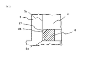
- FIG. 2 is an enlarged view of part A in FIG.
- the frame 2 which is the housing of the rotary electric machine 1 has a substantially cylindrical shape having an opening on the rear side (upper side of the drawing), and is made of an inexpensive and lightweight aluminum alloy.
- the stator 3 is formed by laminating electromagnetic steel sheets, and the stator winding 5 is wound via an insulator 4 which is an insulator, and terminals 6 and terminals 6 for supplying an electric current to the stator winding 5 are provided.
- a holder 7 for fixing is installed.
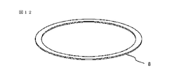
- the annular member 8 is an annular member, and a perspective view is shown in FIG.
- the annular member 8 is made of polyacetal resin, fluororesin, etc., which has a lower hardness than the aluminum alloy which is the material of the frame 2 and has excellent wear resistance, and has a chamfered portion 8a at the upper and lower edges on the outer peripheral side of the square cross section. It has a ring shape with 8b, and the outer diameter 8c is set to be larger than the hole diameter 2a of the frame 2 like the outer diameter 3a of the stator 3.
- the annular member 8 and the stator 3 are press-fitted in the order of the annular member 8 and the stator 3 from the opening on the rear side of the frame 2, and the annular member 8 and the stator 3 come into contact with each other. Will be installed.
- a bearing 9 is fixed to the frame 2 from the front side via a bearing holder 10 made of carbon steel from the rear side.
- a rotor 14 on which a magnet 13 is installed is fixed to the rotor shaft 12, and the rotor shaft 12 is rotatably supported by a bearing 9 and a bearing 11.
- the rotor 14 is arranged so as to be separated from the stator 3 and surrounded by the rotor 14. Further, a boss 15 for assembling with the vehicle side is installed at the end of the rotor shaft 12 in the front direction, and a rotation angle for detecting the rotational state of the rotor 14 is provided at the omitted portion of the rotor shaft 12 in the rear direction.
- a detection sensor is installed.
- reference numeral 16 denotes a heat sink in which a control device (not shown) is installed, and this heat sink 16 is fixed to the rear opening of the frame 2.
- the control device includes a power conversion circuit and a control circuit having a power semiconductor that converts a direct current from the outside, and a required current is supplied to the stator winding 5 via the terminal 6. As a result, a rotational force is generated in the rotor 14, and the rotor shaft 12 and the boss 15 are rotated.
- the annular member 8 and the stator 3 are set in the rear opening of the frame 2, and by applying a load to the stator 3, they are guided to the chamfered portion 8a of the annular member 8 and the press-fitting introduction taper 2b of the frame 2, and are annular.
- the member 8 is press-fitted into the frame 2. Since the annular member 8 has a hardness lower than that of the frame 2, is flexible and has excellent wear resistance, the frame 2 is not scraped during the press-fitting process.
- the edge portion 3b on the press-fitting tip side of the stator 3 is guided by the press-fitting introduction taper 2b of the frame 2, and then hits the press-fitting introduction portion edge 2c, so that the stress is locally excessive, and thread burr-like shavings, That is, foreign matter generated in the manufacturing process of the rotary electric machine is generated and adheres to the edge portion 3b of the stator 3, or falls off into the space 17 surrounded by the chamfered portion 8b of the annular member 8, the stator 3, and the frame 2. Or something.
- the contact surface with the frame 2 has a step due to the laminating, and the frame is made of an aluminum-based material having low hardness even during press fitting. 2 is scraped and adheres to the edge portion 3b of the stator 3, or falls off into the space 17 surrounded by the chamfered portion 8b of the annular member 8, the stator 3, and the frame 2. These shavings do not come out of the enclosed space 17 even if vibration, impact, or the like is applied.
- the shavings move in the frame 2 due to vibration, impact, or the like. If it gets between the stator 3 and the rotor 14 or in the bearings 9 and 11, normal rotation operation is hindered. Further, since the shavings, which are aluminum-based materials, have conductivity, there is a risk of short-circuiting if they adhere between conductive portions such as terminals 6. In the configuration of this embodiment, when the stator 3 is press-fitted into the frame 2, the shavings of the frame 2 are not scattered in the frame 2, and a highly reliable rotary electric machine can be provided.
- the annular member 8 may be made of a porous resin such as a fluorine-based sponge, and the annular member 8 may be impregnated with a lubricant such as mineral oil or liquid paraffin.
- a lubricant such as mineral oil or liquid paraffin.
- the annular member 8 has a quadrangular cross section and has a ring shape having chamfered portions 8a and 8b at the upper and lower edge portions on the outer peripheral side.
- the cross-sectional shape may be another shape as long as it is annular, such as one having a circular ring-shaped cross section.
- the above-mentioned thread burr-like shavings that is, foreign matter generated in the manufacturing process of the rotary electric machine, is held in the annular space 17 extending over the entire inner circumference of the frame 2, and the foreign matter is present. Moves from the region of space 17 to a region other than the region of space 17, for example, a gap 314 g between the stator 3 and the rotor 14, the coil end portion of the stator 3, bearings 9, 11 and the like. Is prevented.
- Embodiment 2 The rotary electric machine according to the second embodiment of the present application will be described with reference to FIGS. 6 to 8. Similar to the first embodiment, this embodiment also shows an example applied to the electric power steering mounted on the vehicle.
- FIG. 6 is a cross-sectional view for explaining the configuration of the rotary electric machine according to the second embodiment
- FIG. 7 is an enlarged view of part A of FIG.
- FIG. 8 is a diagram illustrating a press-fitting process.
- the annular member 8 and the stator 3 are formed as separate bodies, and are set and press-fitted into the rear opening of the frame 2, respectively.
- the stator 3 and the annular member 8 are integrated. It is configured to be press-fitted.
- the stator 3 is formed by laminating electromagnetic steel plates, and the press-fitting tip side has a small diameter portion 3c smaller than the outer diameter 3a, and the small diameter portion 3c has a hardness lower than that of the aluminum alloy which is the material of the frame 2.
- An annular member 8 made of a polyacetal resin, a fluororesin, or the like having excellent wear resistance is fixed or outsert molded.
- the outer diameter 8c of the annular member 8 is set to be larger than the hole diameter 2a of the frame 2 like the outer diameter 3a of the stator 3, and is press-fitted into the frame 2 together with the stator 3.
- Other configurations and operations are the same as those in the first embodiment.
- the annular member 8 is integrated with the stator 3, the workability of press fitting is good. Further, even when the annular member 8 is made of a porous resin such as a fluorine-based sponge and the annular member 8 is impregnated with a lubricant such as mineral oil or liquid paraffin as in the first embodiment, the annular member 8 is not touched. Since the lubricant can be impregnated and press-fitted, the work environment is not polluted and the work efficiency is improved.
- Embodiment 3 The rotary electric machine according to the third embodiment of the present application will be described with reference to FIGS. 9 to 12. Similar to the first and second embodiments, this embodiment also shows an example applied to the electric power steering mounted on the vehicle. 9 is a cross-sectional view for explaining the configuration of the rotary electric machine according to the third embodiment, and FIG. 10 is an enlarged view of part A of FIG. FIG. 11 is a diagram illustrating a press-fitting process.
- the annular member 8 has a rectangular cross section and a sheet shape as shown in the perspective view of FIG. 12, and is arranged on the frame 2.
- the annular member 8 does not necessarily have to be press-fitted into the frame 2.
- the annular member 8 may be outsert-molded on the frame 2. In this state, the stator 3 is press-fitted so as to come into contact with the annular member 8.
- the annular member 8 By using the annular member 8 as a material that is more flexible and elastic than an aluminum alloy such as resin, the annular member 8 can be brought into close contact with the stator 3 without a gap.
- the annular member 8 By forming the annular member 8 with a material having a Young's modulus lower than that of the aluminum alloy which is the material of the frame 2, In this case, the shavings adhering to the edge portion 3b of the stator 3 and the shavings dropped on the annular member 8 are sandwiched between the contact portions between the annular member 8 and the stator 3 when the press-fitting of the stator 3 is completed. Therefore, even if vibration, impact, etc. are applied, it will not be scattered in the frame 2.
- the shavings that have fallen off during the press-fitting process do not stick to the adhesive portion of the annular member 8 and do not move, so that the shavings do not move. Can be more reliably prevented from being scattered in the frame 2.
- Embodiment 4 Although the configurations in which the stator 3 formed by laminating the electromagnetic steel plates are directly press-fitted into the frame 2 have been described above in the first to third embodiments, the fourth embodiment of the present application illustrated in FIGS. 13 to 15 has been described. As described above, the stator 3 may be applied to a stator 3 which is press-fitted and fixed to a thin-walled cylindrical member 18 formed of carbon steel or the like.
- FIG. 14 is an enlarged view of part A in FIG. 13, and FIG. 15 is a diagram illustrating a press-fitting process. As is clear from FIGS.
- the press-fitting surface in contact with the frame 2 has no step formed by laminating the electromagnetic steel sheets of the stator 3, so that the press-fitting is performed. It is possible to suppress scraping of the frame 2 and provide a more reliable rotary electric machine.
- the first to fourth embodiments of the present application generally have the following features.
- Feature 1 A rotor shaft supported by a bearing, a rotor attached to the rotor shaft and rotating together with the rotor shaft, and the rotor surrounded by a gap 314 g so that the rotor can rotate.
- the stator, the rotor, and the frame surrounding the rotor and having the outer circumference of the stator attached to the inner circumference, and the entire circumference of the outer circumference extending over the entire inner circumference of the frame.
- stator is arranged on the front side of the child, the stator is formed of an electromagnetic laminated steel plate, the stator is press-fitted into the frame in the extending direction of the rotor shaft, and the annular member is the stator. It is arranged so as to be located in front of the press-fitting portion 3p in the direction of the press-fitting.
- the rotor shaft, the rotor fixed to the rotor shaft, the stator formed by laminating an electromagnetic laminated steel plate and arranged so as to surround the rotor, and the stator were wound around the stator.
- It is a rotary electric machine including a stator winding, a frame for press-fitting and holding the stator, and an annular member arranged in contact with the front of the press-fitting portion 3p of the stator in the press-fitting direction. Therefore, it is possible to prevent the shavings of the frame from being scattered inside the rotary electric machine, and it is possible to prevent the shavings from hindering the rotation and short-circuiting the energization of the stator winding.
- Feature 2 Since the annular member is press-fitted into the frame, it is possible to prevent the shavings of the frame from being scattered inside the rotary electric machine, the rotation is hindered by the shavings, and the stator winding is energized. Can be prevented from being short-circuited. In addition, the cost of shrink fitting can be eliminated.
- Feature 3 Since a space surrounded by the annular member, the stator, and the frame is formed, it is possible to more reliably prevent the shavings of the frame from being scattered inside the rotating electric machine, and the shavings rotate. Can be prevented from being hindered or short-circuiting the energization of the stator winding.
- Feature 4 The annular member is fixed to the stator, and the annular member is integrated with the stator, so that press-fitting workability is good.
- Feature 5 Since the annular member is made of a material having a hardness lower than that of the frame, it is possible to prevent the shavings of the frame from being scattered inside the rotating electric machine, and the shavings hinder the rotation or the stator winding. It is possible to prevent short-circuiting the energization to.
- Feature 6 Since the annular member is impregnated with a lubricant, the lubricant impregnated in the annular member is uniformly applied to the press-fitting surface of the frame and the stator, making it difficult to wear and generating shavings. It can be suppressed.
- Feature 7 Since the annular member is arranged on the frame and the annular member is fixed to the frame, the shavings are sandwiched between the contact portion between the annular member and the stator when the press-fitting of the stator is completed. Therefore, even if vibration or shock is applied, it will not be scattered in the frame.
- the annular member is made of a material having a Young's modulus lower than that of the frame, the annular member is made of a material that is more flexible and elastic than an aluminum alloy such as resin, so that the annular member adheres tightly to the stator.
- the shavings are sandwiched between the contact portion between the annular member and the stator, and are not scattered in the frame even if vibration or impact is applied.
- Feature 9 Since a part or the whole of the annular member has adhesiveness, in other words, at least a part of the annular member has the annular member adhered to at least one of the stator and the frame. By making the annular member sticky, the shavings that have fallen off during the press-fitting process do not stick and move, and the press-fitting of the stator is completed for the shavings. At this point, it is sandwiched between the contact portion between the annular member and the stator, and even if vibration, impact, etc. are applied, it does not scatter in the frame.
- Feature 10 Since the stator is held around by a thin-walled cylindrical member, in other words, the outer circumference of the stator is covered with a cylindrical member, and the stator is interposed via the cylindrical member. Since it is attached to the frame, the press-fitting surface that comes into contact with the frame eliminates the step formed by laminating the electromagnetic steel plates of the stator, which suppresses the frame from being scraped by press-fitting and makes rotation more reliable. Can provide electrical equipment.
- Feature 11 A rotor shaft supported by a bearing, a rotor attached to the rotor shaft and rotating together with the rotor shaft, and surrounding the rotor through a gap so that the rotor can rotate.
- a frame that surrounds the stator, the rotor, and the stator and has the outer circumference of the stator attached to the inner circumference, and is arranged so that the outer circumference extends over the entire circumference of the inner circumference of the frame. It is a rotary electric machine provided with an annular member that prevents residual foreign matter remaining at the boundary portion between the frame and the stator from moving to a region different from the boundary portion, and is generated in the manufacturing process and fixed to the frame.
- Residual foreign matter such as frame shavings remaining at the boundary portion with the child is in a region different from the boundary portion, for example, between the coil end portion of the stator winding, the bearing, the rotor and the stator. It moves to a region such as a gap during the process of manufacturing a rotary electric machine including the process of assembling the rotary electric machine, the process of assembling the rotary electric machine to a vehicle including a two-wheeled vehicle, or during the vibration of the rotary electric machine while the vehicle is in operation. It is possible to prevent unfavorable effects on the coil end portion, the bearing, the gap, and the like.
- each figure the same sign indicates the same or corresponding part.
- each embodiment can be modified, omitted, or combined as appropriate.
- the present application describes various exemplary embodiments and examples, the various features, embodiments, and functions described in one or more embodiments are specific embodiments. It is not limited to the application of, but can be applied to the embodiment alone or in various combinations. Therefore, innumerable variations not illustrated are envisioned within the scope of the techniques disclosed in the present application. For example, it is assumed that at least one component is modified, added or omitted, and further, at least one component is extracted and combined with the components of other embodiments.
Abstract
A rotary electrical machine according to the present invention comprises: a rotor shaft (12) supported by bearings (9), (11); a rotor (14) which is attached to the rotor shaft (12) and rotates with the rotor shaft (12); a stator (3) which surrounds the rotor (14) with a gap (314g) therebetween so as to be able to rotate the rotor (14); a frame (2) which surrounds the rotor (14) and the stator (3), and has the outer circumference of the stator (3) attached to the inner circumference thereof; and an annular member which is provided along the inner circumference of the frame (2) and prevents foreign matter in a boundary portion between the frame (2) and the stator (3) from moving to a region different from that boundary portion, wherein foreign matter, such as shavings of the frame, produced in the rotary electrical machine manufacturing process are prevented from being dispersed inside the rotary electrical machine.
Description
本願は回転電機に関するものである。
This application relates to a rotary electric machine.
従来から、車両に搭載される回転電機において、フレームの内周面に固定子が圧入固定され、固定子の内側に回転子が設置されているものが知られている。(例えば特許文献1)
特開2016-136829
Conventionally, in a rotary electric machine mounted on a vehicle, a stator is press-fitted and fixed to the inner peripheral surface of a frame, and a rotor is installed inside the stator. (For example, Patent Document 1)
JP 2016-136829
車両に搭載される回転電機には燃費向上のため軽量化の要求がある。また、エンジンルーム内に設置されて使用されることも多く、温度変化、振動等に対する耐久性が要求されている。さらに、エンジンルーム内では設置できる空間に限りがあるため、回転電機の径方向の寸法の小型化も要求されている。
回転電機の固定子はフレームの内周面に固定されるが、所定の保持力で固定するためには、フレームの内径よりも固定子の外径を大きくして、固定子をフレームで締付ける必要がある。フレームをアルミニウム系材料等で構成すれば安価に軽量化を図れるが、固定子は電磁鋼板等を積層して形成されるため、固定子のフレームとの接触面には当該積層による段差があり、固定子を固定する際にフレームに固定子を圧入すると硬度の低いアルミニウム系材料のフレームが削れ、回転電機内部にフレームの削り屑が散乱したり、フレームを損傷したりする問題があった。また、固定子をフレームに直接圧入することをせずに、焼嵌めを用いて固定子をフレームに固定することも可能であるが、その場合は設備費等により製造コストが増加する問題があった。 There is a demand for weight reduction of rotary electric machines mounted on vehicles in order to improve fuel efficiency. In addition, it is often installed and used in an engine room, and durability against temperature changes, vibrations, etc. is required. Further, since the space that can be installed in the engine room is limited, it is required to reduce the radial dimension of the rotary electric machine.
The stator of the rotary electric machine is fixed to the inner peripheral surface of the frame, but in order to fix it with a predetermined holding force, it is necessary to make the outer diameter of the stator larger than the inner diameter of the frame and tighten the stator with the frame. There is. If the frame is made of aluminum-based material, etc., the weight can be reduced at low cost. However, since the stator is formed by laminating electromagnetic steel plates, etc., the contact surface of the stator with the frame has a step due to the laminating. When the stator is press-fitted into the frame when fixing the stator, the frame made of an aluminum-based material having low hardness is scraped, and there is a problem that shavings of the frame are scattered inside the rotary electric machine or the frame is damaged. It is also possible to fix the stator to the frame by shrink fitting without directly press-fitting the stator to the frame, but in that case, there is a problem that the manufacturing cost increases due to equipment costs and the like. rice field.
本願は、上記のような実情に鑑みてなされた技術を開示するものであり、フレームの削り屑などの回転電機の製造過程で発生する異物が回転電機内部に散乱するのを防止することを目的とする。
The present application discloses a technique made in view of the above circumstances, and an object of the present application is to prevent foreign substances generated in the manufacturing process of a rotating electric machine such as shavings of a frame from being scattered inside the rotating electric machine. And.
本願に開示される回転電機は、軸受によって支承された回転子軸、前記回転子軸に取り付けられ前記回転子軸と共に回転する回転子、前記回転子の前記回転ができるように前記回転子を空隙を介して囲繞する固定子、前記回転子および前記固定子を囲繞し内周に前記固定子の外周が取り付けられたフレーム、および前記フレームの内周に沿って設けられ前記フレームと前記固定子との境界部分に存在する異物が前記境界部分とは異なる領域へ移動するのを防ぐ環状部材を備えたものである。
The rotor electric machine disclosed in the present application has a rotor shaft supported by a bearing, a rotor attached to the rotor shaft and rotating together with the rotor shaft, and a gap between the rotor so that the rotor can rotate. A stator surrounding the rotor, a frame surrounding the rotor and the stator and having the outer circumference of the stator attached to the inner circumference, and the frame and the stator provided along the inner circumference of the frame. It is provided with an annular member that prevents foreign matter existing at the boundary portion of the above-mentioned boundary portion from moving to a region different from the boundary portion.
本願に開示される回転電機では、軸受によって支承された回転子軸、前記回転子軸に取り付けられ前記回転子軸と共に回転する回転子、前記回転子の前記回転ができるように前記回転子を空隙を介して囲繞する固定子、前記回転子および前記固定子を囲繞し内周に前記固定子の外周が取り付けられたフレーム、および前記フレームの内周に沿って設けられ前記フレームと前記固定子との境界部分に存在する異物が前記境界部分とは異なる領域へ移動するのを防ぐ環状部材を備えているので、フレームの削り屑などの回転電機の製造過程で発生する異物が回転電機内部に散乱するのを防止することが可能となる。
In the rotary electric machine disclosed in the present application, a rotor shaft supported by a bearing, a rotor attached to the rotor shaft and rotating together with the rotor shaft, and the rotor are voided so as to allow the rotation of the rotor. A stator surrounding the rotor, a frame surrounding the rotor and the stator and having the outer circumference of the stator attached to the inner circumference, and the frame and the stator provided along the inner circumference of the frame. Since the annular member that prevents foreign matter existing at the boundary portion from moving to a region different from the boundary portion is provided, foreign matter generated in the manufacturing process of the rotary electric machine such as shavings of the frame is scattered inside the rotary electric machine. It is possible to prevent this from happening.
実施の形態1.
以下に、本願に係る回転電機の実施の形態を図面に基づいて説明する。なお、本願に係る回転電機は以下の記述に限定されるものではなく、本願の要旨を逸脱しない範囲において適宜変更可能である。以下に示す図面においては、理解の容易のため、各部材の縮尺が実際とは異なる場合があり、また、本願の特徴に関係しない構成の図示は省略する。Embodiment 1.
Hereinafter, embodiments of the rotary electric machine according to the present application will be described with reference to the drawings. The rotary electric machine according to the present application is not limited to the following description, and can be appropriately changed without departing from the gist of the present application. In the drawings shown below, the scale of each member may differ from the actual scale for ease of understanding, and the illustration of a configuration not related to the features of the present application is omitted.
以下に、本願に係る回転電機の実施の形態を図面に基づいて説明する。なお、本願に係る回転電機は以下の記述に限定されるものではなく、本願の要旨を逸脱しない範囲において適宜変更可能である。以下に示す図面においては、理解の容易のため、各部材の縮尺が実際とは異なる場合があり、また、本願の特徴に関係しない構成の図示は省略する。
Hereinafter, embodiments of the rotary electric machine according to the present application will be described with reference to the drawings. The rotary electric machine according to the present application is not limited to the following description, and can be appropriately changed without departing from the gist of the present application. In the drawings shown below, the scale of each member may differ from the actual scale for ease of understanding, and the illustration of a configuration not related to the features of the present application is omitted.
図1から図5を用いて本願の実施の形態1による回転電機を説明する。
本実施の形態1では、回転電機を車両に搭載する電動パワーステアリングに適用した例を示している。車両のステアリングの操舵力をアシスタントするには回転電機以外に制御装置も必要になるが、制御装置についての図示を省略している。図1は回転電機の構成を説明するための断面図であり、図2は図1におけるA部の拡大図である。 The rotary electric machine according to the first embodiment of the present application will be described with reference to FIGS. 1 to 5.
In the first embodiment, an example in which the rotary electric machine is applied to the electric power steering mounted on the vehicle is shown. A control device is required in addition to the rotary electric machine to assist the steering force of the vehicle steering, but the illustration of the control device is omitted. FIG. 1 is a cross-sectional view for explaining the configuration of a rotary electric machine, and FIG. 2 is an enlarged view of part A in FIG.
回転電機1の筐体であるフレーム2はリア側(図面上側)に開口部を有した略円筒形をなし、安価で軽量なアルミニウム合金で形成されている。固定子3は電磁鋼板を積層して形成され、絶縁体であるインシュレータ4を介して固定子巻線5が巻装され、固定子巻線5に電流を供給するためのターミナル6とターミナル6を固定するためのホルダ7が設置されている。
The frame 2 which is the housing of the rotary electric machine 1 has a substantially cylindrical shape having an opening on the rear side (upper side of the drawing), and is made of an inexpensive and lightweight aluminum alloy. The stator 3 is formed by laminating electromagnetic steel sheets, and the stator winding 5 is wound via an insulator 4 which is an insulator, and terminals 6 and terminals 6 for supplying an electric current to the stator winding 5 are provided. A holder 7 for fixing is installed.
8は環状部材であり、斜視図を図3に示す。環状部材8は、フレーム2の材料であるアルミニウム合金より硬度低く、耐摩耗性に優れたポリアセタール樹脂、フッ素樹脂、等で形成され、断面が四角形の外周側の上下のエッジ部に面取り部8a、8bを有した環形状をなし、外径8cは固定子3の外径3aと同様に、フレーム2の穴径2aより大きくなるように設定されている。環状部材8と固定子3とは、図4に矢印で示すように、フレーム2のリア側の開口部から環状部材8、固定子3の順に圧入され、環状部材8と固定子3は接触して設置される。
8 is an annular member, and a perspective view is shown in FIG. The annular member 8 is made of polyacetal resin, fluororesin, etc., which has a lower hardness than the aluminum alloy which is the material of the frame 2 and has excellent wear resistance, and has a chamfered portion 8a at the upper and lower edges on the outer peripheral side of the square cross section. It has a ring shape with 8b, and the outer diameter 8c is set to be larger than the hole diameter 2a of the frame 2 like the outer diameter 3a of the stator 3. As shown by the arrows in FIG. 4, the annular member 8 and the stator 3 are press-fitted in the order of the annular member 8 and the stator 3 from the opening on the rear side of the frame 2, and the annular member 8 and the stator 3 come into contact with each other. Will be installed.
フレーム2にはフロント側に軸受9とリア側から炭素鋼からなる軸受ホルダ10を介して軸受11が固定されている。
回転子軸12は磁石13が設置された回転子14が固定され、軸受9および軸受11によって回転可能に支持される。なお、回転子14は固定子3と離間して囲まれるように配置されている。
また、回転子軸12のフロント方向の端部には車両側と組付けるためのボス15が設置され、回転子軸12のリア方向の省略部分には回転子14の回転状態を検出する回転角度検出センサが設置されている。 Abearing 9 is fixed to the frame 2 from the front side via a bearing holder 10 made of carbon steel from the rear side.
Arotor 14 on which a magnet 13 is installed is fixed to the rotor shaft 12, and the rotor shaft 12 is rotatably supported by a bearing 9 and a bearing 11. The rotor 14 is arranged so as to be separated from the stator 3 and surrounded by the rotor 14.
Further, aboss 15 for assembling with the vehicle side is installed at the end of the rotor shaft 12 in the front direction, and a rotation angle for detecting the rotational state of the rotor 14 is provided at the omitted portion of the rotor shaft 12 in the rear direction. A detection sensor is installed.
回転子軸12は磁石13が設置された回転子14が固定され、軸受9および軸受11によって回転可能に支持される。なお、回転子14は固定子3と離間して囲まれるように配置されている。
また、回転子軸12のフロント方向の端部には車両側と組付けるためのボス15が設置され、回転子軸12のリア方向の省略部分には回転子14の回転状態を検出する回転角度検出センサが設置されている。 A
A
Further, a
ここで、16は制御装置(図示せず)が設置されているヒートシンクであり、このヒートシンク16はフレーム2のリア側開口部に固定されている。制御装置は外部からの直流電流を変換するパワー半導体を有する電力変換回路と制御回路を具備しており、所要の電流がターミナル6を介して固定子巻線5に供給される。これにより回転子14に回転力を発生させ、回転子軸12、ひいてはボス15を回転させる。
Here, reference numeral 16 denotes a heat sink in which a control device (not shown) is installed, and this heat sink 16 is fixed to the rear opening of the frame 2. The control device includes a power conversion circuit and a control circuit having a power semiconductor that converts a direct current from the outside, and a required current is supplied to the stator winding 5 via the terminal 6. As a result, a rotational force is generated in the rotor 14, and the rotor shaft 12 and the boss 15 are rotated.
次に環状部材8と固定子3をフレーム2に圧入するときの作用を図4で説明する。まず、環状部材8と固定子3はフレーム2のリア側開口部にセットされ、固定子3に荷重を加えることで環状部材8の面取り部8aとフレーム2の圧入導入テーパ2bに導かれ、環状部材8がフレーム2に圧入される。環状部材8はフレーム2より硬度低く、柔軟で耐摩耗性に優れた材料のため圧入過程でフレーム2を削ることはない。
次に固定子3の圧入先端側のエッジ部3bはフレーム2の圧入導入テーパ2bに導かれた後、圧入導入部エッジ2cに当たることにより局所的に応力が過大となり、糸バリ状の削り屑、つまり回転電機の製造過程で発生した異物、が発生し、固定子3のエッジ部3bに付着したり、環状部材8の面取り部8bと固定子3とフレーム2で囲まれた空間17に脱落したりする。 Next, the operation when theannular member 8 and the stator 3 are press-fitted into the frame 2 will be described with reference to FIG. First, the annular member 8 and the stator 3 are set in the rear opening of the frame 2, and by applying a load to the stator 3, they are guided to the chamfered portion 8a of the annular member 8 and the press-fitting introduction taper 2b of the frame 2, and are annular. The member 8 is press-fitted into the frame 2. Since the annular member 8 has a hardness lower than that of the frame 2, is flexible and has excellent wear resistance, the frame 2 is not scraped during the press-fitting process.
Next, theedge portion 3b on the press-fitting tip side of the stator 3 is guided by the press-fitting introduction taper 2b of the frame 2, and then hits the press-fitting introduction portion edge 2c, so that the stress is locally excessive, and thread burr-like shavings, That is, foreign matter generated in the manufacturing process of the rotary electric machine is generated and adheres to the edge portion 3b of the stator 3, or falls off into the space 17 surrounded by the chamfered portion 8b of the annular member 8, the stator 3, and the frame 2. Or something.
次に固定子3の圧入先端側のエッジ部3bはフレーム2の圧入導入テーパ2bに導かれた後、圧入導入部エッジ2cに当たることにより局所的に応力が過大となり、糸バリ状の削り屑、つまり回転電機の製造過程で発生した異物、が発生し、固定子3のエッジ部3bに付着したり、環状部材8の面取り部8bと固定子3とフレーム2で囲まれた空間17に脱落したりする。 Next, the operation when the
Next, the
また、固定子3は電磁鋼板を積層して形成されるため、フレーム2との接触面には積層による段差があり、圧入している最中も硬度の低いアルミニウム系材料で形成されているフレーム2が削れ、固定子3のエッジ部3bに付着したり、環状部材8の面取り部8bと固定子3とフレーム2で囲まれた空間17に脱落したりする。これらの削り屑は、振動・衝撃等が加わっても密閉された空間17から出ることはない。
Further, since the stator 3 is formed by laminating electromagnetic steel plates, the contact surface with the frame 2 has a step due to the laminating, and the frame is made of an aluminum-based material having low hardness even during press fitting. 2 is scraped and adheres to the edge portion 3b of the stator 3, or falls off into the space 17 surrounded by the chamfered portion 8b of the annular member 8, the stator 3, and the frame 2. These shavings do not come out of the enclosed space 17 even if vibration, impact, or the like is applied.
環状部材8が無い場合は、上記削り屑は振動・衝撃等によりフレーム2の中で移動する。固定子3と回転子14の間または軸受9、11の中に入り込むと正常な回転動作を妨げられる。また、アルミニウム系材料である削り屑は導電性があるため、ターミナル6等の導電部の間に付着すると短絡する恐れがある。
本実施例の構成では、固定子3をフレーム2に圧入する際、フレーム2の削り屑がフレーム2内に散乱することがなく、信頼性の高い回転電機を提供できる。 When theannular member 8 is not provided, the shavings move in the frame 2 due to vibration, impact, or the like. If it gets between the stator 3 and the rotor 14 or in the bearings 9 and 11, normal rotation operation is hindered. Further, since the shavings, which are aluminum-based materials, have conductivity, there is a risk of short-circuiting if they adhere between conductive portions such as terminals 6.
In the configuration of this embodiment, when thestator 3 is press-fitted into the frame 2, the shavings of the frame 2 are not scattered in the frame 2, and a highly reliable rotary electric machine can be provided.
本実施例の構成では、固定子3をフレーム2に圧入する際、フレーム2の削り屑がフレーム2内に散乱することがなく、信頼性の高い回転電機を提供できる。 When the
In the configuration of this embodiment, when the
次に、本実施の形態において環状部材8を多孔質樹脂、例えばフッ素系スポンジ等で構成し、環状部材8に鉱油または流動パラフィン等の潤滑剤を含侵させてもよい。環状部材8をフレーム2に圧入する際、環状部材8に含侵された潤滑剤がフレーム2と固定子3の圧入面に均一に塗布され、摩耗しにくくなり、削り屑の発生を抑制することができる。
Next, in the present embodiment, the annular member 8 may be made of a porous resin such as a fluorine-based sponge, and the annular member 8 may be impregnated with a lubricant such as mineral oil or liquid paraffin. When the annular member 8 is press-fitted into the frame 2, the lubricant impregnated in the annular member 8 is uniformly applied to the press-fitting surfaces of the frame 2 and the stator 3, making it difficult to wear and suppressing the generation of shavings. Can be done.
また、本実施の形態では、環状部材8は断面が四角形で外周側の上下のエッジ部に面取り部8a、8bを有した環形状をなしているが、図5に示す斜視図のようなOリング状の断面が円形のもの等、環状であれば断面形状は他の形状としてもよい。
環状部材8の断面を円形あるいは図2に例示のような多角形とすることにより、環状部材8と固定子3とフレーム2とで囲まれフレーム2の内周の全周に亘って延在する円環状の空間17が形成される。フレーム2の内周の全周に亘って延在する円環状の空間17の中に、前述の糸バリ状の削り屑、つまり回転電機の製造過程で発生した異物、が保持され、当該異物は、空間17の領域から、空間17の領域以外の領域、例えば、固定子3と回転子14との間の空隙314g、固定子3のコイルエンド部、軸受9,11等の領域、へ移動するのが防止される。 Further, in the present embodiment, theannular member 8 has a quadrangular cross section and has a ring shape having chamfered portions 8a and 8b at the upper and lower edge portions on the outer peripheral side. The cross-sectional shape may be another shape as long as it is annular, such as one having a circular ring-shaped cross section.
By forming the cross section of theannular member 8 into a circle or a polygon as shown in FIG. 2, the annular member 8 is surrounded by the annular member 8, the stator 3, and the frame 2, and extends over the entire inner circumference of the frame 2. An annular space 17 is formed. The above-mentioned thread burr-like shavings, that is, foreign matter generated in the manufacturing process of the rotary electric machine, is held in the annular space 17 extending over the entire inner circumference of the frame 2, and the foreign matter is present. Moves from the region of space 17 to a region other than the region of space 17, for example, a gap 314 g between the stator 3 and the rotor 14, the coil end portion of the stator 3, bearings 9, 11 and the like. Is prevented.
環状部材8の断面を円形あるいは図2に例示のような多角形とすることにより、環状部材8と固定子3とフレーム2とで囲まれフレーム2の内周の全周に亘って延在する円環状の空間17が形成される。フレーム2の内周の全周に亘って延在する円環状の空間17の中に、前述の糸バリ状の削り屑、つまり回転電機の製造過程で発生した異物、が保持され、当該異物は、空間17の領域から、空間17の領域以外の領域、例えば、固定子3と回転子14との間の空隙314g、固定子3のコイルエンド部、軸受9,11等の領域、へ移動するのが防止される。 Further, in the present embodiment, the
By forming the cross section of the
実施の形態2.
図6から図8を用いて本願の実施の形態2による回転電機を説明する。本形態も実施の形態1と同様、車両に搭載する電動パワーステアリングに適用した例を示している。
図6は実施の形態2における回転電機の構成を説明するための断面図で図7は図6のA部拡大図である。図8は圧入工程を説明する図である。Embodiment 2.
The rotary electric machine according to the second embodiment of the present application will be described with reference to FIGS. 6 to 8. Similar to the first embodiment, this embodiment also shows an example applied to the electric power steering mounted on the vehicle.
FIG. 6 is a cross-sectional view for explaining the configuration of the rotary electric machine according to the second embodiment, and FIG. 7 is an enlarged view of part A of FIG. FIG. 8 is a diagram illustrating a press-fitting process.
図6から図8を用いて本願の実施の形態2による回転電機を説明する。本形態も実施の形態1と同様、車両に搭載する電動パワーステアリングに適用した例を示している。
図6は実施の形態2における回転電機の構成を説明するための断面図で図7は図6のA部拡大図である。図8は圧入工程を説明する図である。
The rotary electric machine according to the second embodiment of the present application will be described with reference to FIGS. 6 to 8. Similar to the first embodiment, this embodiment also shows an example applied to the electric power steering mounted on the vehicle.
FIG. 6 is a cross-sectional view for explaining the configuration of the rotary electric machine according to the second embodiment, and FIG. 7 is an enlarged view of part A of FIG. FIG. 8 is a diagram illustrating a press-fitting process.
実施の形態1では環状部材8と固定子3は別体で構成し、フレーム2のリア側開口部にそれぞれセットし圧入したが、本実施の形態2では、固定子3と環状部材8を一体化し圧入する構成としている。
In the first embodiment, the annular member 8 and the stator 3 are formed as separate bodies, and are set and press-fitted into the rear opening of the frame 2, respectively. However, in the second embodiment, the stator 3 and the annular member 8 are integrated. It is configured to be press-fitted.
図において、固定子3は電磁鋼板を積層して形成され、圧入先端側は外径3aより寸法が小さい小径部3cを有し、小径部3cにフレーム2の材料であるアルミニウム合金より硬度低く、耐摩耗性に優れたポリアセタール樹脂、フッ素樹脂、等で形成された環状部材8が固定またはアウトサート成型されている。
環状部材8の外径8cは固定子3の外径3aと同様に、フレーム2の穴径2aより大きくなるように設定され、固定子3とともにフレーム2に圧入されている。
その他の構成、作用は実施の形態1と同様である。 In the figure, thestator 3 is formed by laminating electromagnetic steel plates, and the press-fitting tip side has a small diameter portion 3c smaller than the outer diameter 3a, and the small diameter portion 3c has a hardness lower than that of the aluminum alloy which is the material of the frame 2. An annular member 8 made of a polyacetal resin, a fluororesin, or the like having excellent wear resistance is fixed or outsert molded.
Theouter diameter 8c of the annular member 8 is set to be larger than the hole diameter 2a of the frame 2 like the outer diameter 3a of the stator 3, and is press-fitted into the frame 2 together with the stator 3.
Other configurations and operations are the same as those in the first embodiment.
環状部材8の外径8cは固定子3の外径3aと同様に、フレーム2の穴径2aより大きくなるように設定され、固定子3とともにフレーム2に圧入されている。
その他の構成、作用は実施の形態1と同様である。 In the figure, the
The
Other configurations and operations are the same as those in the first embodiment.
環状部材8は固定子3と一体になっているため、圧入の作業性がよい。また、実施の形態1のように環状部材8を多孔質樹脂、例えばフッ素系スポンジ等で構成し、環状部材8に鉱油または流動パラフィン等の潤滑剤を含侵させる場合も環状部材8に触れずに潤滑剤の含侵、圧入が可能なため、作業環境を汚すことが無く、作業効率が向上する。
Since the annular member 8 is integrated with the stator 3, the workability of press fitting is good. Further, even when the annular member 8 is made of a porous resin such as a fluorine-based sponge and the annular member 8 is impregnated with a lubricant such as mineral oil or liquid paraffin as in the first embodiment, the annular member 8 is not touched. Since the lubricant can be impregnated and press-fitted, the work environment is not polluted and the work efficiency is improved.
実施の形態3.
図9から図12を用いて本願の実施の形態3による回転電機を説明する。本形態も実施の形態1,2と同様、車両に搭載する電動パワーステアリングに適用した例を示している。
図9は実施の形態3における回転電機の構成を説明するための断面図で図10は図9のA部拡大図である。図11は圧入工程を説明する図である。Embodiment 3.
The rotary electric machine according to the third embodiment of the present application will be described with reference to FIGS. 9 to 12. Similar to the first and second embodiments, this embodiment also shows an example applied to the electric power steering mounted on the vehicle.
9 is a cross-sectional view for explaining the configuration of the rotary electric machine according to the third embodiment, and FIG. 10 is an enlarged view of part A of FIG. FIG. 11 is a diagram illustrating a press-fitting process.
図9から図12を用いて本願の実施の形態3による回転電機を説明する。本形態も実施の形態1,2と同様、車両に搭載する電動パワーステアリングに適用した例を示している。
図9は実施の形態3における回転電機の構成を説明するための断面図で図10は図9のA部拡大図である。図11は圧入工程を説明する図である。
The rotary electric machine according to the third embodiment of the present application will be described with reference to FIGS. 9 to 12. Similar to the first and second embodiments, this embodiment also shows an example applied to the electric power steering mounted on the vehicle.
9 is a cross-sectional view for explaining the configuration of the rotary electric machine according to the third embodiment, and FIG. 10 is an enlarged view of part A of FIG. FIG. 11 is a diagram illustrating a press-fitting process.
図9から図12において環状部材8は、図12に斜視図を示すように断面が長方形でシート形状をなし、フレーム2に配設されている。この場合、環状部材8は必ずしもフレーム2に圧入されている必要はない。また、環状部材8はフレーム2にアウトサート成型してもよい。この状態で固定子3を環状部材8に接触するように圧入する。
9 to 12, the annular member 8 has a rectangular cross section and a sheet shape as shown in the perspective view of FIG. 12, and is arranged on the frame 2. In this case, the annular member 8 does not necessarily have to be press-fitted into the frame 2. Further, the annular member 8 may be outsert-molded on the frame 2. In this state, the stator 3 is press-fitted so as to come into contact with the annular member 8.
環状部材8を樹脂等のアルミニウム合金より柔軟で弾力性のある材料とすることで、環状部材8を、固定子3と隙間なく密着させることができる。
環状部材8を、フレーム2の材料であるアルミニウム合金よりヤング率が低い材料で形成することにより、
この場合、固定子3のエッジ部3bに付着した削り屑、環状部材8上に落下した削り屑は固定子3の圧入が完了した時点で、環状部材8と固定子3との接触部に挟まれ、振動、衝撃等が加わってもフレーム2内に散乱することがない。
さらに、環状部材8の一部または全体に粘着性を持たせることにより、環状部材8の粘着性を有する部分に、圧入過程において脱落した削り屑が貼りつき、移動することがないため、削り屑がフレーム2内に散乱することを、より確実に防止することができる。 By using theannular member 8 as a material that is more flexible and elastic than an aluminum alloy such as resin, the annular member 8 can be brought into close contact with the stator 3 without a gap.
By forming theannular member 8 with a material having a Young's modulus lower than that of the aluminum alloy which is the material of the frame 2,
In this case, the shavings adhering to theedge portion 3b of the stator 3 and the shavings dropped on the annular member 8 are sandwiched between the contact portions between the annular member 8 and the stator 3 when the press-fitting of the stator 3 is completed. Therefore, even if vibration, impact, etc. are applied, it will not be scattered in the frame 2.
Further, by making a part or the whole of theannular member 8 adhesive, the shavings that have fallen off during the press-fitting process do not stick to the adhesive portion of the annular member 8 and do not move, so that the shavings do not move. Can be more reliably prevented from being scattered in the frame 2.
環状部材8を、フレーム2の材料であるアルミニウム合金よりヤング率が低い材料で形成することにより、
この場合、固定子3のエッジ部3bに付着した削り屑、環状部材8上に落下した削り屑は固定子3の圧入が完了した時点で、環状部材8と固定子3との接触部に挟まれ、振動、衝撃等が加わってもフレーム2内に散乱することがない。
さらに、環状部材8の一部または全体に粘着性を持たせることにより、環状部材8の粘着性を有する部分に、圧入過程において脱落した削り屑が貼りつき、移動することがないため、削り屑がフレーム2内に散乱することを、より確実に防止することができる。 By using the
By forming the
In this case, the shavings adhering to the
Further, by making a part or the whole of the
実施の形態4.
以上、実施の形態1から3は電磁鋼板を積層して形成されている固定子3を直接フレーム2に圧入する構成について説明したが、図13から図15に例示の本願の実施の形態4のように固定子3は炭素鋼等から形成された薄肉円筒状部材18に圧入固定しているものにも適用してもよい。
図14は図13におけるA部の拡大図であり、図15は圧入工程を説明する図である。
図13、図14、および図15から明白なように、本実施の形態4場合、フレーム2と接触する圧入面は固定子3の電磁鋼板を積層して形成される段差がなくなるため、圧入によりフレーム2が削れることを抑制し、より信頼性の高い回転電機を提供できる。Embodiment 4.
Although the configurations in which thestator 3 formed by laminating the electromagnetic steel plates are directly press-fitted into the frame 2 have been described above in the first to third embodiments, the fourth embodiment of the present application illustrated in FIGS. 13 to 15 has been described. As described above, the stator 3 may be applied to a stator 3 which is press-fitted and fixed to a thin-walled cylindrical member 18 formed of carbon steel or the like.
FIG. 14 is an enlarged view of part A in FIG. 13, and FIG. 15 is a diagram illustrating a press-fitting process.
As is clear from FIGS. 13, 14, and 15, in the case of the fourth embodiment, the press-fitting surface in contact with theframe 2 has no step formed by laminating the electromagnetic steel sheets of the stator 3, so that the press-fitting is performed. It is possible to suppress scraping of the frame 2 and provide a more reliable rotary electric machine.
以上、実施の形態1から3は電磁鋼板を積層して形成されている固定子3を直接フレーム2に圧入する構成について説明したが、図13から図15に例示の本願の実施の形態4のように固定子3は炭素鋼等から形成された薄肉円筒状部材18に圧入固定しているものにも適用してもよい。
図14は図13におけるA部の拡大図であり、図15は圧入工程を説明する図である。
図13、図14、および図15から明白なように、本実施の形態4場合、フレーム2と接触する圧入面は固定子3の電磁鋼板を積層して形成される段差がなくなるため、圧入によりフレーム2が削れることを抑制し、より信頼性の高い回転電機を提供できる。
Although the configurations in which the
FIG. 14 is an enlarged view of part A in FIG. 13, and FIG. 15 is a diagram illustrating a press-fitting process.
As is clear from FIGS. 13, 14, and 15, in the case of the fourth embodiment, the press-fitting surface in contact with the
本願の実施の形態1から4は、総括的には、次のような特徴事項を有している。
特徴事項1:軸受によって支承された回転子軸、前記回転子軸に取り付けられ前記回転子軸と共に回転する回転子、前記回転子の前記回転ができるように前記回転子を空隙314gを介して囲繞する固定子、前記回転子および前記固定子を囲繞し内周に前記固定子の外周が取り付けられたフレーム、および外周の全周が前記フレームの内周の全周に亘って延在し前記フレームの前記内周と前記固定子の外周との間の部分に存在する異物が前記間の部分以外の領域へ移動するのを防ぐ環状部材を備えた回転電機であり、前記環状部材は、前記固定子のフロント側に配設されており、前記固定子は電磁積層鋼板で形成され前記固定子が前記フレームに前記回転子軸の延在方向に圧入されており、前記環状部材が、前記固定子の圧入部3pより前記圧入の方向の前方に位置して配設されている。換言すれば、回転子軸と前記回転子軸に固定された回転子と、電磁積層鋼板を積層して形成され前記回転子を囲むように配置された固定子と前記固定子に巻装された固定子巻線と、前記固定子を圧入保持するフレームと、前記固定子の圧入部3pより圧入の方向の前方に接触配置した環状部材を備えた回転電機である。従って、フレームの削り屑が回転電機内部に散乱することを防止でき、削り屑により回転が妨げられたり、固定子巻き線への通電を短絡させたりすることを防止できる。 The first to fourth embodiments of the present application generally have the following features.
Feature 1: A rotor shaft supported by a bearing, a rotor attached to the rotor shaft and rotating together with the rotor shaft, and the rotor surrounded by agap 314 g so that the rotor can rotate. The stator, the rotor, and the frame surrounding the rotor and having the outer circumference of the stator attached to the inner circumference, and the entire circumference of the outer circumference extending over the entire inner circumference of the frame. It is a rotary electric machine provided with an annular member that prevents foreign matter existing in a portion between the inner circumference of the stator and the outer circumference of the stator from moving to a region other than the portion between the rotors, and the annular member is the fixing. The stator is arranged on the front side of the child, the stator is formed of an electromagnetic laminated steel plate, the stator is press-fitted into the frame in the extending direction of the rotor shaft, and the annular member is the stator. It is arranged so as to be located in front of the press-fitting portion 3p in the direction of the press-fitting. In other words, the rotor shaft, the rotor fixed to the rotor shaft, the stator formed by laminating an electromagnetic laminated steel plate and arranged so as to surround the rotor, and the stator were wound around the stator. It is a rotary electric machine including a stator winding, a frame for press-fitting and holding the stator, and an annular member arranged in contact with the front of the press-fitting portion 3p of the stator in the press-fitting direction. Therefore, it is possible to prevent the shavings of the frame from being scattered inside the rotary electric machine, and it is possible to prevent the shavings from hindering the rotation and short-circuiting the energization of the stator winding.
特徴事項1:軸受によって支承された回転子軸、前記回転子軸に取り付けられ前記回転子軸と共に回転する回転子、前記回転子の前記回転ができるように前記回転子を空隙314gを介して囲繞する固定子、前記回転子および前記固定子を囲繞し内周に前記固定子の外周が取り付けられたフレーム、および外周の全周が前記フレームの内周の全周に亘って延在し前記フレームの前記内周と前記固定子の外周との間の部分に存在する異物が前記間の部分以外の領域へ移動するのを防ぐ環状部材を備えた回転電機であり、前記環状部材は、前記固定子のフロント側に配設されており、前記固定子は電磁積層鋼板で形成され前記固定子が前記フレームに前記回転子軸の延在方向に圧入されており、前記環状部材が、前記固定子の圧入部3pより前記圧入の方向の前方に位置して配設されている。換言すれば、回転子軸と前記回転子軸に固定された回転子と、電磁積層鋼板を積層して形成され前記回転子を囲むように配置された固定子と前記固定子に巻装された固定子巻線と、前記固定子を圧入保持するフレームと、前記固定子の圧入部3pより圧入の方向の前方に接触配置した環状部材を備えた回転電機である。従って、フレームの削り屑が回転電機内部に散乱することを防止でき、削り屑により回転が妨げられたり、固定子巻き線への通電を短絡させたりすることを防止できる。 The first to fourth embodiments of the present application generally have the following features.
Feature 1: A rotor shaft supported by a bearing, a rotor attached to the rotor shaft and rotating together with the rotor shaft, and the rotor surrounded by a
特徴事項2:前記環状部材は、前記フレームに圧入されているので、フレームの削り屑が回転電機内部に散乱することを防止でき、削り屑により回転が妨げられたり、固定子巻き線への通電を短絡させたりすることを防止できる。また、焼嵌めの備費を不要にできる。
Feature 2: Since the annular member is press-fitted into the frame, it is possible to prevent the shavings of the frame from being scattered inside the rotary electric machine, the rotation is hindered by the shavings, and the stator winding is energized. Can be prevented from being short-circuited. In addition, the cost of shrink fitting can be eliminated.
特徴事項3:前記環状部材と前記固定子と前記フレームとで囲まれた空間が形成されているので、フレームの削り屑が回転電機内部に散乱することをより確実に防止でき、削り屑により回転が妨げられたり、固定子巻き線への通電を短絡させたりすることを防止できる。
Feature 3: Since a space surrounded by the annular member, the stator, and the frame is formed, it is possible to more reliably prevent the shavings of the frame from being scattered inside the rotating electric machine, and the shavings rotate. Can be prevented from being hindered or short-circuiting the energization of the stator winding.
特徴事項4:前記環状部材は、前記固定子に固定されており、環状部材は固定子と一体になっているため、圧入の作業性がよい。
Feature 4: The annular member is fixed to the stator, and the annular member is integrated with the stator, so that press-fitting workability is good.
特徴事項5:前記環状部材は前記フレームより硬度が低い材料からなっているので、フレームの削り屑が回転電機内部に散乱することを防止でき、削り屑により回転が妨げられたり、固定子巻き線への通電を短絡させたりすることを防止できる。
Feature 5: Since the annular member is made of a material having a hardness lower than that of the frame, it is possible to prevent the shavings of the frame from being scattered inside the rotating electric machine, and the shavings hinder the rotation or the stator winding. It is possible to prevent short-circuiting the energization to.
特徴事項6:前記環状部材は潤滑剤が含浸されているので、環状部材に含侵された潤滑剤がフレームと固定子の圧入面に均一に塗布され、摩耗しにくくなり、削り屑の発生を抑制することができる。
Feature 6: Since the annular member is impregnated with a lubricant, the lubricant impregnated in the annular member is uniformly applied to the press-fitting surface of the frame and the stator, making it difficult to wear and generating shavings. It can be suppressed.
特徴事項7:前記環状部材は前記フレームに配置され、前記環状部材は前記フレームに固定されているので、削り屑は固定子の圧入が完了した時点で、環状部材と固定子の接触部に挟まれ、振動・衝撃等が加わってもフレーム内に散乱することがない。
Feature 7: Since the annular member is arranged on the frame and the annular member is fixed to the frame, the shavings are sandwiched between the contact portion between the annular member and the stator when the press-fitting of the stator is completed. Therefore, even if vibration or shock is applied, it will not be scattered in the frame.
特徴事項8:前記環状部材は、前記フレームよりヤング率が低い材料からなっているので、環状部材を樹脂等のアルミニウム合金より柔軟で弾力性のある材料とすることで、固定子と隙間なく密着させることができ、削り屑は固定子の圧入が完了した時点で、環状部材と固定子の接触部に挟まれ、振動・衝撃等が加わってもフレーム内に散乱することがない。
Feature 8: Since the annular member is made of a material having a Young's modulus lower than that of the frame, the annular member is made of a material that is more flexible and elastic than an aluminum alloy such as resin, so that the annular member adheres tightly to the stator. When the press-fitting of the stator is completed, the shavings are sandwiched between the contact portion between the annular member and the stator, and are not scattered in the frame even if vibration or impact is applied.
特徴事項9:前記環状部材の一部または全体は粘着性を有しているので、換言すれば、前記環状部材の少なくとも一部は、前記固定子および前記フレームの少なくとも一方に前記環状部材が粘着されるように粘着性を有しているので、環状部材に粘着性を持たせることにより、圧入過程において脱落した削り屑が貼りつき移動することがなく、削り屑は固定子の圧入が完了した時点で、環状部材と固定子の接触部に挟まれ、振動・衝撃等が加わってもフレーム内に散乱することがない。
Feature 9: Since a part or the whole of the annular member has adhesiveness, in other words, at least a part of the annular member has the annular member adhered to at least one of the stator and the frame. By making the annular member sticky, the shavings that have fallen off during the press-fitting process do not stick and move, and the press-fitting of the stator is completed for the shavings. At this point, it is sandwiched between the contact portion between the annular member and the stator, and even if vibration, impact, etc. are applied, it does not scatter in the frame.
特徴事項10:前記固定子は周囲を薄肉円筒状部材で保持されているので、換言すれば、前記固定子の外周は円筒状部材で覆われており、前記固定子は前記円筒状部材を介して前記フレームに取り付けられているので、フレームと接触する圧入面は固定子の電磁鋼板を積層して形成される段差がなくなるため、圧入によりフレームが削れることを抑制し、より信頼性の高い回転電機を提供できる。
Feature 10: Since the stator is held around by a thin-walled cylindrical member, in other words, the outer circumference of the stator is covered with a cylindrical member, and the stator is interposed via the cylindrical member. Since it is attached to the frame, the press-fitting surface that comes into contact with the frame eliminates the step formed by laminating the electromagnetic steel plates of the stator, which suppresses the frame from being scraped by press-fitting and makes rotation more reliable. Can provide electrical equipment.
特徴事項11:軸受によって支承された回転子軸、前記回転子軸に取り付けられ前記回転子軸と共に回転する回転子、前記回転子の前記回転ができるように前記回転子を空隙を介して囲繞する固定子、前記回転子および前記固定子を囲繞し内周に前記固定子の外周が取り付けられたフレーム、および外周が前記フレームの内周の周方向全周に亘って延在するように配設され前記フレームと前記固定子との境界部分に残存する残留異物が前記境界部分とは異なる領域へ移動するのを防ぐ環状部材を備えた回転電機であり、製造過程で発生し前記フレームと前記固定子との境界部分に残存したフレームの削り屑などの残留異物が、前記境界部分とは異なる領域、例えば、前記固定子巻線のコイルエンド部、前記軸受、回転子と固定子との間の空隙、等の領域に、回転電機の組み立て工程を含む回転電機製造過程で、二輪車を含む車両への回転電機の組付け過程で、あるいは車両の運転中における回転電機の振動中に、移動するのが防止され、コイルエンド部、前記軸受、前記空隙、等において好ましくない影響が生じないようにすることが可能である。
Feature 11: A rotor shaft supported by a bearing, a rotor attached to the rotor shaft and rotating together with the rotor shaft, and surrounding the rotor through a gap so that the rotor can rotate. A frame that surrounds the stator, the rotor, and the stator and has the outer circumference of the stator attached to the inner circumference, and is arranged so that the outer circumference extends over the entire circumference of the inner circumference of the frame. It is a rotary electric machine provided with an annular member that prevents residual foreign matter remaining at the boundary portion between the frame and the stator from moving to a region different from the boundary portion, and is generated in the manufacturing process and fixed to the frame. Residual foreign matter such as frame shavings remaining at the boundary portion with the child is in a region different from the boundary portion, for example, between the coil end portion of the stator winding, the bearing, the rotor and the stator. It moves to a region such as a gap during the process of manufacturing a rotary electric machine including the process of assembling the rotary electric machine, the process of assembling the rotary electric machine to a vehicle including a two-wheeled vehicle, or during the vibration of the rotary electric machine while the vehicle is in operation. It is possible to prevent unfavorable effects on the coil end portion, the bearing, the gap, and the like.
なお、各図中、同一符合は同一または相当部分を示す。
なお、各実施の形態を適宜、変形、省略、組み合わせることができる。
なお、本願は、様々な例示的な実施の形態及び実施例が記載されているが、1つ、または複数の実施の形態に記載された様々な特徴、態様、及び機能は特定の実施の形態の適用に限られるのではなく、単独で、または様々な組み合わせで実施の形態に適用可能である。
従って、例示されていない無数の変形例が、本願に開示される技術の範囲内において想定される。例えば、少なくとも1つの構成要素を変形する場合、追加する場合または省略する場合、さらには、少なくとも1つの構成要素を抽出し、他の実施の形態の構成要素と組み合わせる場合が含まれるものとする。 In each figure, the same sign indicates the same or corresponding part.
In addition, each embodiment can be modified, omitted, or combined as appropriate.
Although the present application describes various exemplary embodiments and examples, the various features, embodiments, and functions described in one or more embodiments are specific embodiments. It is not limited to the application of, but can be applied to the embodiment alone or in various combinations.
Therefore, innumerable variations not illustrated are envisioned within the scope of the techniques disclosed in the present application. For example, it is assumed that at least one component is modified, added or omitted, and further, at least one component is extracted and combined with the components of other embodiments.
1 回転電機、2 フレーム、2a 穴径、2b 圧入導入テーパ、2c 圧入導入部エッジ、3 固定子、3a 外径、3b エッジ部、3c 小径部、3p 圧入部、4 インシュレータ、5 固定子巻線、6 ターミナル、7 ホルダ、8 環状部材、8a 面取り部、8b 面取り部、8c 外径、9 軸受、10 軸受ホルダ、11 軸受、12 回転子軸、13 磁石、14 回転子、15 ボス、16 ヒートシンク、17 空間、18 薄肉円筒状部材、314g 空隙。
1 Rotor, 2 frame, 2a hole diameter, 2b press-fitting introduction taper, 2c press-fitting introduction part edge, 3 stator, 3a outer diameter, 3b edge part, 3c small diameter part, 3p press-fitting part, 4 insulator, 5 stator winding , 6 terminal, 7 holder, 8 annular member, 8a chamfer, 8b chamfer, 8c outer diameter, 9 bearing, 10 bearing holder, 11 bearing, 12 rotor shaft, 13 magnet, 14 rotor, 15 boss, 16 heat sink , 17 space, 18 thin-walled cylindrical member, 314 g void.
Claims (12)
- 軸受によって支承された回転子軸、
前記回転子軸に取り付けられ前記回転子軸と共に回転する回転子、
前記回転子の前記回転ができるように前記回転子を空隙を介して囲繞する固定子、
前記回転子および前記固定子を囲繞し内周に前記固定子の外周が取り付けられたフレーム、および
前記フレームの内周に沿って設けられ前記フレームと前記固定子との境界部分に存在する異物が前記境界部分とは異なる領域へ移動するのを防ぐ環状部材を備えた回転電機。 Rotor shafts supported by bearings,
A rotor attached to the rotor shaft and rotating with the rotor shaft,
A stator that surrounds the rotor through a gap so that the rotor can rotate.
A frame that surrounds the rotor and the stator and has the outer periphery of the stator attached to the inner circumference, and foreign matter that is provided along the inner circumference of the frame and exists at the boundary between the frame and the stator. A rotary electric machine provided with an annular member that prevents movement to a region different from the boundary portion. - 前記環状部材は、前記固定子のフロント側に配設されていることを特徴とする請求項1に記載の回転電機。 The rotary electric machine according to claim 1, wherein the annular member is arranged on the front side of the stator.
- 前記固定子は電磁積層鋼板で形成され前記固定子が前記フレームに前記回転子軸の延在方向に圧入されており、前記環状部材が、前記固定子の圧入部より前記圧入の方向の前方に位置して配設されていることを特徴とする請求項1または請求項2に記載の回転電機。 The stator is formed of an electromagnetic laminated steel plate, and the stator is press-fitted into the frame in the extending direction of the rotor shaft, and the annular member is forward of the press-fitting portion of the stator in the press-fitting direction. The rotary electric machine according to claim 1 or 2, wherein the rotary electric machine is arranged so as to be positioned.
- 前記環状部材は、前記フレームに圧入されていることを特徴とする請求項1から請求項3のいずれか一項に記載の回転電機。 The rotary electric machine according to any one of claims 1 to 3, wherein the annular member is press-fitted into the frame.
- 前記環状部材と前記固定子と前記フレームとで囲まれた空間が形成されていることを特徴とする請求項1から請求項4のいずれか一項に記載の回転電機。 The rotary electric machine according to any one of claims 1 to 4, wherein a space surrounded by the annular member, the stator, and the frame is formed.
- 前記環状部材は、前記固定子に固定されていることを特徴とする請求項1から請求項5のいずれか一項に記載の回転電機。 The rotary electric machine according to any one of claims 1 to 5, wherein the annular member is fixed to the stator.
- 前記環状部材は、前記フレームに固定されていることを特徴とする請求項1から請求項5のいずれか一項に記載の回転電機。 The rotary electric machine according to any one of claims 1 to 5, wherein the annular member is fixed to the frame.
- 前記環状部材の硬度は、前記フレームの硬度より低いことを特徴とする請求項1から請求項7のいずれか一項に記載の回転電機。 The rotary electric machine according to any one of claims 1 to 7, wherein the hardness of the annular member is lower than the hardness of the frame.
- 前記環状部材には、潤滑剤が含浸されていることを特徴とする請求項1から請求項8のいずれか一項に記載の回転電機。 The rotary electric machine according to any one of claims 1 to 8, wherein the annular member is impregnated with a lubricant.
- 前記環状部材は、前記フレームよりヤング率が低い材料からなることを特徴とする請求項1から請求項9のいずれか一項に記載の回転電機。 The rotary electric machine according to any one of claims 1 to 9, wherein the annular member is made of a material having a Young's modulus lower than that of the frame.
- 前記環状部材の少なくとも一部は、前記固定子および前記フレームの少なくとも一方に前記環状部材が粘着されるように粘着性を有していることを特徴とする請求項1から請求項10のいずれか一項に記載の回転電機。 Any of claims 1 to 10, wherein at least a part of the annular member has adhesiveness so that the annular member is adhered to at least one of the stator and the frame. The rotary electric machine described in item 1.
- 前記固定子の外周は円筒状部材で覆われており、前記固定子は前記円筒状部材を介して前記フレームに取り付けられていることを特徴とする請求項1から請求項11のいずれか一項に記載の回転電機。 Any one of claims 1 to 11, wherein the outer periphery of the stator is covered with a cylindrical member, and the stator is attached to the frame via the cylindrical member. The rotary electric machine described in.
Priority Applications (5)
| Application Number | Priority Date | Filing Date | Title |
|---|---|---|---|
| US17/800,408 US20230099339A1 (en) | 2020-04-02 | 2020-04-02 | Rotating electrical machine |
| EP20928760.6A EP4131738A4 (en) | 2020-04-02 | 2020-04-02 | Rotary electrical machine |
| CN202080098825.5A CN115336145A (en) | 2020-04-02 | 2020-04-02 | Rotating electrical machine |
| JP2022511459A JP7466628B2 (en) | 2020-04-02 | 2020-04-02 | Rotating Electric Machine |
| PCT/JP2020/015169 WO2021199399A1 (en) | 2020-04-02 | 2020-04-02 | Rotary electrical machine |
Applications Claiming Priority (1)
| Application Number | Priority Date | Filing Date | Title |
|---|---|---|---|
| PCT/JP2020/015169 WO2021199399A1 (en) | 2020-04-02 | 2020-04-02 | Rotary electrical machine |
Publications (1)
| Publication Number | Publication Date |
|---|---|
| WO2021199399A1 true WO2021199399A1 (en) | 2021-10-07 |
Family
ID=77927510
Family Applications (1)
| Application Number | Title | Priority Date | Filing Date |
|---|---|---|---|
| PCT/JP2020/015169 WO2021199399A1 (en) | 2020-04-02 | 2020-04-02 | Rotary electrical machine |
Country Status (5)
| Country | Link |
|---|---|
| US (1) | US20230099339A1 (en) |
| EP (1) | EP4131738A4 (en) |
| JP (1) | JP7466628B2 (en) |
| CN (1) | CN115336145A (en) |
| WO (1) | WO2021199399A1 (en) |
Citations (5)
| Publication number | Priority date | Publication date | Assignee | Title |
|---|---|---|---|---|
| JPH0458062U (en) * | 1990-09-26 | 1992-05-19 | ||
| JP2004309334A (en) * | 2003-04-08 | 2004-11-04 | Denso Corp | Pressure sensing device |
| WO2016076166A1 (en) * | 2014-11-11 | 2016-05-19 | 株式会社ミツバ | Brushless wiper motor |
| JP2016136829A (en) | 2015-01-14 | 2016-07-28 | 株式会社ジェイテクト | Motor unit |
| JP2020054197A (en) * | 2018-09-28 | 2020-04-02 | 日本電産サーボ株式会社 | Motor device |
Family Cites Families (3)
| Publication number | Priority date | Publication date | Assignee | Title |
|---|---|---|---|---|
| JP6318056B2 (en) * | 2014-09-05 | 2018-04-25 | 日立オートモティブシステムズ株式会社 | Rotating electric machine housing and rotating electric machine equipped with the same |
| JP2018074685A (en) * | 2016-10-26 | 2018-05-10 | マブチモーター株式会社 | Brushless motor |
| DE102016222614A1 (en) * | 2016-11-17 | 2018-05-17 | Robert Bosch Gmbh | Stator of an electrical machine, an electric machine, and method for producing such |
-
2020
- 2020-04-02 WO PCT/JP2020/015169 patent/WO2021199399A1/en unknown
- 2020-04-02 CN CN202080098825.5A patent/CN115336145A/en active Pending
- 2020-04-02 US US17/800,408 patent/US20230099339A1/en active Pending
- 2020-04-02 JP JP2022511459A patent/JP7466628B2/en active Active
- 2020-04-02 EP EP20928760.6A patent/EP4131738A4/en active Pending
Patent Citations (5)
| Publication number | Priority date | Publication date | Assignee | Title |
|---|---|---|---|---|
| JPH0458062U (en) * | 1990-09-26 | 1992-05-19 | ||
| JP2004309334A (en) * | 2003-04-08 | 2004-11-04 | Denso Corp | Pressure sensing device |
| WO2016076166A1 (en) * | 2014-11-11 | 2016-05-19 | 株式会社ミツバ | Brushless wiper motor |
| JP2016136829A (en) | 2015-01-14 | 2016-07-28 | 株式会社ジェイテクト | Motor unit |
| JP2020054197A (en) * | 2018-09-28 | 2020-04-02 | 日本電産サーボ株式会社 | Motor device |
Non-Patent Citations (1)
| Title |
|---|
| See also references of EP4131738A4 |
Also Published As
| Publication number | Publication date |
|---|---|
| US20230099339A1 (en) | 2023-03-30 |
| EP4131738A1 (en) | 2023-02-08 |
| JP7466628B2 (en) | 2024-04-12 |
| CN115336145A (en) | 2022-11-11 |
| EP4131738A4 (en) | 2023-05-24 |
| JPWO2021199399A1 (en) | 2021-10-07 |
Similar Documents
| Publication | Publication Date | Title |
|---|---|---|
| JP5488614B2 (en) | Stator core fixing structure and rotating electric machine having the same | |
| JP5894030B2 (en) | motor | |
| US20080247689A1 (en) | Motor | |
| CN209767318U (en) | Electric actuator | |
| US6940193B2 (en) | Spindle motor with an electro-conductive connection between the bearing system and the baseplate or flange | |
| JP2007135342A (en) | Dynamo-electric machine | |
| WO2008068910A1 (en) | Polygon mirror scanner motor and method of manufacturing the same | |
| WO2021199399A1 (en) | Rotary electrical machine | |
| WO2019155541A1 (en) | Control device-integrated rotary electric machine | |
| WO2014061156A1 (en) | Electric motor and manufacturing method | |
| JP2010041884A (en) | Rotary electric machine for vehicle | |
| WO2016079819A1 (en) | Rotary electric machine and device integrated with rotary electric machine | |
| KR102405080B1 (en) | Robot drive system comprising harmonic drive | |
| JP2008283750A (en) | Motor for hydraulic damper | |
| JP2011142702A (en) | Disk drive device | |
| WO2017122289A1 (en) | Rotary electric machine and vibratory device | |
| JP2012231564A (en) | Motor | |
| JP2004340183A (en) | Fluid bearing device | |
| CN215596312U (en) | Electric actuator | |
| JP2020045985A (en) | Electric actuator | |
| WO2021171556A1 (en) | Electric motor, fan, and air conditioner | |
| JP4309222B2 (en) | Motor and power steering device | |
| JP6762610B2 (en) | Brushless motor | |
| JP2022116858A (en) | Electric actuator and method for manufacturing electric actuator | |
| JP2023082275A (en) | Method and structure for fixing bearing |
Legal Events
| Date | Code | Title | Description |
|---|---|---|---|
| 121 | Ep: the epo has been informed by wipo that ep was designated in this application |
Ref document number: 20928760 Country of ref document: EP Kind code of ref document: A1 |
|
| ENP | Entry into the national phase |
Ref document number: 2022511459 Country of ref document: JP Kind code of ref document: A |
|
| NENP | Non-entry into the national phase |
Ref country code: DE |
|
| ENP | Entry into the national phase |
Ref document number: 2020928760 Country of ref document: EP Effective date: 20221102 |