JP2010041884A - Rotary electric machine for vehicle - Google Patents
Rotary electric machine for vehicle Download PDFInfo
- Publication number
- JP2010041884A JP2010041884A JP2008204543A JP2008204543A JP2010041884A JP 2010041884 A JP2010041884 A JP 2010041884A JP 2008204543 A JP2008204543 A JP 2008204543A JP 2008204543 A JP2008204543 A JP 2008204543A JP 2010041884 A JP2010041884 A JP 2010041884A
- Authority
- JP
- Japan
- Prior art keywords
- detected
- side metal
- rotating shaft
- metal portion
- section
- Prior art date
- Legal status (The legal status is an assumption and is not a legal conclusion. Google has not performed a legal analysis and makes no representation as to the accuracy of the status listed.)
- Granted
Links
Images


Abstract
Description
本発明は、乗用車やトラック等に搭載される車両用交流発電機や発電電動機等の車両用回転電機に関する。 The present invention relates to a vehicular rotating electrical machine such as a vehicular AC generator or a generator motor mounted on a passenger car, a truck, or the like.
従来から、回転軸の端部に回転位置検出部を固定するようにした回転電機が知られている(例えば、特許文献1参照。)。この回転位置検出部の固定は、円環板に4個の丸孔を設け、これらの丸孔にねじ等の締結具を貫通させて回転軸に締め付けることにより行われる。
ところで、特許文献1に開示された回転位置検出部の取り付け構造では、締結具を取り付けるための丸孔の公差の関係で取り付け位置(軸方向位置および周方向位置)にばらつきがあり、回転位置の検出精度が低下するという問題があった。また、ねじ等の締結具が必要であり、部品点数や取り付けのための工数が増加し、これらに伴ってコストが増加するとともに、目標の位置に回転位置検出部が取り付けられるように位置調整を行う場合にはさらに工数がかかり、さらなるコスト増加は避けられない。
By the way, in the attachment structure of the rotational position detection part disclosed by
本発明は、このような点に鑑みて創作されたものであり、その目的は、回転位置の検出精度の向上とコストダウンを図ることができる車両用回転電機を提供することにある。 The present invention was created in view of the above points, and an object of the present invention is to provide a vehicular rotating electrical machine capable of improving the detection accuracy of the rotational position and reducing the cost.
上述した課題を解決するために、本発明の車両用回転電機は、界磁巻線と電気的に接続される一対のスリップリングを有する回転軸を含む回転子と、スリップリングに摺接する一対のブラシとこれら一対のブラシを収納する収納部が形成されたブラシホルダとブラシホルダとともにスリップリングを覆うカバー部材とを有するブラシ装置と、回転軸の一端に配置された回転位置被検出部と、回転位置被検出部の回転位置を検出する回転位置検出部とを備えており、回転位置被検出部は、永久磁石と被検出部側金属部が樹脂により一体成形されており、回転軸の一端を形成する回転軸側金属部に被検出部側金属部を圧入することにより固定されている。 In order to solve the above-described problems, a rotating electrical machine for a vehicle according to the present invention includes a rotor including a rotating shaft having a pair of slip rings electrically connected to a field winding, and a pair of sliding contacts with the slip rings. A brush device having a brush, a brush holder in which a housing portion for housing the pair of brushes is formed, and a cover member that covers the slip ring together with the brush holder; a rotational position detected portion disposed at one end of the rotation shaft; A rotation position detection unit that detects a rotation position of the position detection unit, and the rotation position detection unit includes a permanent magnet and a metal part to be detected that are integrally formed of resin, and one end of the rotation shaft is provided. It is fixed by press-fitting the detected part side metal part into the rotating shaft side metal part to be formed.
被検出部側金属部を回転軸側金属部に圧入することにより、ねじ等の部品を追加することなく回転位置被検出部の固定を確実に行うことができる。また、圧入により固定する際に回転位置被検出部の軸方向位置や周方向位置を同時に調整することができるため、回転位置検出精度を向上させることができ、しかも、調整のための工程が不要になってコストダウンを図ることができる。さらに、永久磁石と被検出部側金属部とを樹脂により一体成形することにより、別々に用意して組み付ける場合に比べて部品点数の削減によるコストダウンが可能になるとともに、高速回転時にも確実に永久磁石を保持して耐久保持力を増すことができる。 By press-fitting the detected portion side metal portion into the rotating shaft side metal portion, the rotational position detected portion can be reliably fixed without adding parts such as screws. Moreover, since the axial position and the circumferential position of the rotational position detected part can be adjusted simultaneously when fixing by press-fitting, the rotational position detection accuracy can be improved, and an adjustment process is unnecessary. Therefore, the cost can be reduced. In addition, by integrally molding the permanent magnet and the metal part to be detected with resin, it is possible to reduce costs by reducing the number of parts compared to separately preparing and assembling, and reliably at high speed rotation The permanent magnet can be held to increase the durability holding force.
また、上述した被検出部側金属部は凸形状を有し、回転軸側金属部は凸形状に嵌合する凹形状を有することが望ましい。これにより、被検出部側金属部と回転軸側金属部の嵌合部分を回転軸内に設定することができるため、回転位置被検出部を固定した際の軸長を短くすることができる。 Moreover, it is desirable that the above-described detected-part-side metal part has a convex shape, and the rotating shaft-side metal part has a concave shape that fits into the convex shape. Thereby, since the fitting part of a to-be-detected part side metal part and a rotating shaft side metal part can be set in a rotating shaft, the axial length at the time of fixing a rotation position detected part can be shortened.
また、上述した被検出部側金属部は、永久磁石の端面よりも突出していることが望ましい。回転位置被検出部を回転軸に圧入する際に、被検出部側金属部の端部を押圧して回転位置被検出部の固定を行うことができるため、永久磁石および樹脂へ加わるストレスを低減することができる。 Moreover, it is desirable that the above-described detected-part-side metal part protrude beyond the end face of the permanent magnet. When the rotational position detected part is press-fitted into the rotating shaft, the end of the detected part side metal part can be pressed to fix the rotational position detected part, thereby reducing the stress applied to the permanent magnet and the resin. can do.
また、上述した被検出部側金属部と回転軸側金属部は、線膨張係数が同等であることが望ましい。これにより、温度上昇時に膨張の程度が異なることによる緩みや過度の締め付けによる応力集中を防止することができる。 In addition, it is desirable that the detected portion side metal portion and the rotating shaft side metal portion have the same linear expansion coefficient. As a result, it is possible to prevent stress concentration due to loosening or excessive tightening due to different degrees of expansion when the temperature rises.
また、上述した被検出部側金属部と回転軸側金属部は、イオン化傾向が近い金属を用いて形成されていることが望ましい。これにより、イオン化の違いによる腐食の発生および進行を防止することができる。 Moreover, it is desirable that the above-described detected portion side metal portion and the rotating shaft side metal portion are formed using a metal having a close ionization tendency. Thereby, generation | occurrence | production and progress of corrosion by the difference in ionization can be prevented.
また、上述した被検出部側金属部には溝が形成されていることが望ましい。これにより、圧入時に回転軸に加わる荷重を低減することができる。 Moreover, it is desirable that a groove is formed in the metal part to be detected described above. Thereby, the load added to a rotating shaft at the time of press injection can be reduced.
以下、本発明の車両用回転電機を適用した一実施形態の車両用交流発電機について、図面を参照しながら詳細に説明する。 Hereinafter, an automotive alternator according to an embodiment to which a rotating electrical machine for a vehicle of the present invention is applied will be described in detail with reference to the drawings.
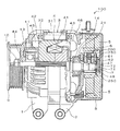
図1は、一実施形態の車両用交流発電機の全体構成を示す図である。図1に示す車両用交流発電機100は、フロント側フレーム1、リア側フレーム2、固定子3、回転子4、制御機器5、ブラシ装置6、回転位置センサ7、リアカバー8、プーリ9等を含んで構成されている。
FIG. 1 is a diagram illustrating an overall configuration of a vehicle AC generator according to an embodiment. 1 includes a
フロント側フレーム1およびリア側フレーム2は、共に椀形状を有しており、これらの開口部同士を対向させて固定子3を挟み込んだ状態で、複数本のボルトによって相互に固定されている。フロント側フレーム1には円筒状のベアリングボックス11が一体に形成されており、リア側フレーム2には鉄製のベアリングボックス21が取り付けられている。固定子3は、固定子鉄心31および固定子巻線32を備えている。
Both the
回転子4は、界磁巻線41、ポールコア42、43、回転軸44等を備えており、ベアリングボックス11、21に収納される一対のベアリング13、14により回転自在に保持されている。ポールコア42、43の軸方向端面には冷却ファン45、46が取り付けられている。また、回転軸44の前端にはプーリ9がナット10により結合されており、図示しない車両エンジンにより回転駆動される。さらに、リア側フレーム2の外側に位置する回転軸44の後端には、界磁巻線41の両端のそれぞれに接続された一対のスリップリング47、48が設けられている。
The rotor 4 includes a field winding 41,
回転位置センサ7は、回転子4の回転位置を検出するものであり、回転軸44の一端に配置されて回転子4とともに回転する円盤状の被検出部(回転位置被検出部)71と、被検出部71の回転位置を検出する検出部(回転位置検出部)72とを含んで構成されている。
The
制御機器5やブラシ装置6等のいわゆる電気部品は、リア側フレーム2の外側の軸方向端面にボルト等の固定手段によって固定されている。制御機器5は、固定子巻線32の出力電圧である三相交流電圧を整流して直流の出力電圧に変換するとともに、界磁巻線41に流れる励磁電流の通電の向きや大きさを制御することにより車両用交流発電機100の出力電圧を制御する。ブラシ装置6は、制御機器5から回転子4の界磁巻線41に励磁電流を流すためのものであり、回転子4の回転軸44に形成されたスリップリング47、48のそれぞれに押圧するブラシ61、62が備わっている。これらの電気部品は、リアカバー8によって覆われている。
So-called electrical components such as the
図2は、車両用交流発電機100をリア側から見た図であり、リアカバー8、制御機器5、回転位置センサ7を取り除いてブラシ装置6が露出した状態が示されている。固定子巻線32は、2組の三相巻線32A、32Bからなり、一方の三相巻線32Aの各相コイルX、Y、Zと他方の三相巻線32Bの各相コイルU、V、Wのそれぞれの端部がリア側フレーム2に設けられた貫通孔を通してリア側に延びている。これらの端部は、制御機器5に接続されている。
FIG. 2 is a view of the
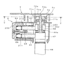
次に、ブラシ装置6と被検出部71の詳細構造について説明する。図3は、ブラシ装置6および回転位置センサ7の断面図である。ブラシ装置6は、ブラシホルダ200、ブラシ61、62、カバー部材250を含んで構成されている。
Next, the detailed structure of the
ブラシホルダ200は、箱型形状を有し、内部に正極側と負極側の2本のブラシ61、62を収納する直方体形状の収納部211、212と、ブラシ61、62のそれぞれから延びた柔軟性を有するリード部としてのピグテール63と電気的に接続されて外部に突出する一対のターミナル221、222とを備えている。ターミナル221、222は、絶縁樹脂製のブラシホルダ200にインサート成形されている。
The
また、カバー部材250は、スリップリング47、48に対して径方向外側および回転軸44の一端(スリップリング47、48側の端部)側に配置されており、ブラシホルダ200とともにスリップリング47、48を覆っている。また、カバー部材250は、回転軸44の一端に対応する位置に、被検出部71の最外径部分よりも小さい直径を有する開口部としての開放部262を有している。
Further, the
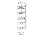
ブラシ61、62は、天然黒鉛に銅粉を含有し、フェノール樹脂などを結合材とした金属黒鉛である。例えば、図4に示す製造工程により製造される。すなわち、原料(天然黒鉛)と結合材(フェノール樹脂)を混合する粉体処理(ステップ100)、銅粉の混合(ステップ101)、ピグテール63の配置(ステップ102)、成形(ステップ103)、焼成(ステップ104)の各工程を経てブラシ61、62が製造される。なお、ブラシ61、62は同一形状であり、同じ形状のものを互いにピグテール63側が向かい合うように配置し、スプリング64を介在させた状態で収納部211、212に収納される。これらのブラシ61、62は、スプリング64によってスリップリング47、48に向けて押圧されて収納部211、212内で摺動接触している。
The
被検出部71は、回転軸44の一端(スリップリング47、48側の端部)に圧入固定されている。また、検出部72は、制御機器5の一部に固定されるとともに被検出部71に対向して配置されており、円盤状の被検出部71の外周近傍領域の回転方向の位置を検出する。具体的な検出方法としては種々の方法が考えられる。例えば、被検出部71の外周近傍に磁性体を配置し、検出部72に設けられた検出コイルでこの磁性体の回転位置を検出したり、被検出部71の外周近傍に磁石を配置し、検出部72に設けられたホール素子でこの磁石の回転位置を検出する場合などが考えられる。なお、上記以外の方法、例えば光センサ等の光学式の検出方法などを用いてもよい。
The detected
図5は、図3のV−V線断面図である。例えば、図3および図5に示すように、被検出部71は、永久磁石71aと被検出部側金属部71bが樹脂71cにより一体成形されている。この被検出部71は、回転軸44の一端を形成する回転軸側金属部44aに被検出部側金属部71bを圧入することにより固定されている。永久磁石71aは、表面に沿って一方向に着磁されたNS磁極を有する。また、検出部72は、この永久磁石71aの外周近傍であって互いに90°隔たった位置に配置された2つのホール素子72a、72bを含んで構成されている。これら2つのホール素子72a、72bの出力に基づいて永久磁石71aの回転位置、すなわち、永久磁石71aが樹脂71cや被検出部側金属部71bを介して固定された回転子4の回転位置の検出が可能になる。
5 is a cross-sectional view taken along line VV in FIG. For example, as shown in FIGS. 3 and 5, in the detected
本実施形態では、被検出部側金属部71bは回転軸44側に側に凸形状(具体的には円柱形状)を有しており、回転軸側金属部44aはこの凸形状に嵌合する、すなわち凸形状の外径よりも若干小さい内径の凹形状を有している。また、被検出部側金属部71bは、永久磁石71aの端面よりもわずかに突出している。
In the present embodiment, the detected-part-
さらに、被検出部側金属部71bと回転軸側金属部44aは、線膨張係数が同等(望ましくは同じ)であり、温度上昇時に膨張の程度が異なることによる緩みや過度の締め付けによる応力集中を防止している。また、被検出部側金属部71bと回転軸側金属部44aは、イオン化傾向が近い金属(望ましくはイオン化傾向が同じ金属)を用いて形成されており、イオン化の違いによる腐食の発生および進行を防止している。
Furthermore, the detected portion
また、回転軸側金属部44aと嵌合する被検出部側金属部71bの外周面には、溝が形成されている。例えば、外周面全体に軸方向に沿って溝(凹凸)を形成してローレットとする場合や、軸方向と垂直な複数の円形溝を形成する場合や、1本あるいは複数本の螺旋状の溝を形成する場合などが考えられる。これにより、圧入時に被検出部側金属部71bの外周面(特に溝間の頂部)が変形しやすくなるため、圧入時に回転軸44に加わる荷重を低減することができる。
In addition, a groove is formed on the outer peripheral surface of the detected portion
また、検出部72とカバー部材250は、天方向からの水やその他の異物の侵入を防止するための迷路構造を形成している。一方、空気は、水やその他の異物に比べて質量が小さいため、検出部72とカバー部材250で形成される迷路構造を通って被検出部71近傍まで到達し、開放部262を経由してスリップリング47、48近傍に導かれる。なお、迷路構造を通って水やその他の異物が被検出部71近傍に到達しても、地方向に設けられた検出部72間の隙間を通して地方向に排出される。
The
上述した回転位置センサ7の被検出部71は、ブラシ装置6を組み付けた後、すなわち、スリップリング47、48の周囲をカバー部材250で覆った状態で、回転軸44の一端に取り付け固定される。これにより、開放部262よりも大きな被検出部71の取り付けが容易となる。
The detected
また、本実施形態では、カバー部材250と検出部72は、回転軸44の径方向に沿った向きに迷路構造を形成している。具体的には、図3に示すように、カバー部材250と検出部72のそれぞれの軸方向位置を部分的に重ねることにより、径方向に沿った迷路構造が形成されている。なお、図3に示す構造では、被検出部71とカバー部材250のそれぞれの軸方向位置および径方向位置を部分的に重ねることにより、これらの間で径方向および軸方向に沿った迷路構造が形成されている。これにより、カバー部材250と検出部72の間の隙間を通して冷却風を導入しつつ(図1では省略したが、リアカバー8には冷却風導入用の貫通孔が形成されており、この貫通孔を通してリアカバー8の外部から内部に冷却風が導入され、その一部がカバー部材250と検出部72の間の隙間に導かれる)、この隙間を通して外部から水の浸入を抑制して耐水性を確保することができる。
In the present embodiment, the
このように、本実施形態の車両用交流発電機100では、被検出部側金属部71bを回転軸側金属部44aに圧入することにより、ねじ等の部品を追加することなく被検出部71の固定を確実に行うことができる。また、圧入により固定する際に被検出部71の軸方向位置や周方向位置を同時に調整することができるため、回転位置検出精度を向上させることができ、しかも、調整のための工程が不要になってコストダウンを図ることができる。さらに、永久磁石71aと被検出部側金属部71bとを樹脂71cにより一体成形することにより、別々に用意して組み付ける場合に比べて部品点数の削減によるコストダウンが可能になるとともに、高速回転時にも確実に永久磁石71aを保持して耐久保持力を増すことができる。
As described above, in the
また、被検出部側金属部71bは凸形状を有し、回転軸側金属部44aは凹形状を有しているため、被検出部側金属部71bと回転軸側金属部44aの嵌合部分を回転軸44内に設定することができ、被検出部71を固定した際の軸長を短くすることができる。
Further, since the detected portion
また、被検出部側金属部71bを永久磁石71aの端面よりも突出させているため、被検出部71を回転軸44に圧入する際に、被検出部側金属部71bの端部を押圧して被検出部71の固定を行うことができるため、永久磁石71aおよび樹脂71cへ加わるストレスを低減することができる。
Further, since the detected portion
なお、本発明は上記実施形態に限定されるものではなく、本発明の要旨の範囲内において種々の変形実施が可能である。上述した実施形態では、被検出部側金属部71bを凸形状に、回転軸側金属部44aを凹形状に形成して、これらを嵌合させたが、凹凸の関係を互いに反対にしてもよい。
In addition, this invention is not limited to the said embodiment, A various deformation | transformation implementation is possible within the range of the summary of this invention. In the above-described embodiment, the detected-part-
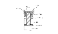
図6は、被検出部の変形例を示す図である。図6に示す被検出部171は、永久磁石171aと被検出部側金属部171bが樹脂171cにより一体成型されている基本構造は被検出部71と同じであるが、以下の点が異なっている。すなわち、図6に示す構造では、被検出部側金属部171bは凹形状を有しており、回転軸44の金属部分を突出させることで形成された凸形状の回転軸金属部144aと嵌合するようになっている。図6に示す構造では、被検出部側金属部171bは永久磁石171aの端面側に突出していないが、被検出部71と同様に、被検出部側金属部171bの一部を凸形状に形成して永久磁石171aの端面よりも突出させるようにしてもよい。また、回転軸側金属部144aの外周面に、ローレットや円形溝、螺旋溝などの溝を形成するようにしてもよい。
FIG. 6 is a diagram illustrating a modification of the detected portion. The detected
また、上述した実施形態では、発電動作を行う車両用交流発電機100について説明したが、固定子に回転磁界を発生させて回転子を駆動する発電電動機に本発明を適用することもできる。
In the above-described embodiment, the
1 フロント側フレーム
2 リア側フレーム
3 固定子
4 回転子
5 制御機器
6 ブラシ装置
7 回転位置センサ
8 リアカバー
9 プーリ
44 回転軸
44a、144a 回転軸側金属部
47、48 スリップリング
61、62 ブラシ
63 ピグテール
64 スプリング
71、171 被検出部
71a、171a 永久磁石
71b、171b 被検出部側金属部
71c、171c 樹脂
72 検出部
100 車両用交流発電機
200 ブラシホルダ
DESCRIPTION OF
Claims (6)
前記回転位置被検出部は、永久磁石と被検出部側金属部が樹脂により一体成形されており、前記回転軸の一端を形成する回転軸側金属部に前記被検出部側金属部を圧入することにより固定されていることを特徴とする車両用回転電機。 A brush holder in which a rotor including a rotating shaft having a pair of slip rings electrically connected to a field winding, a pair of brushes slidably contacting the slip rings, and a storage portion for storing the pair of brushes are formed And a brush device having a cover member that covers the slip ring together with the brush holder, a rotational position detected portion disposed at one end of the rotational shaft, and a rotational position detection that detects a rotational position of the rotational position detected portion A rotating electrical machine for a vehicle comprising:
In the rotational position detected portion, a permanent magnet and a detected portion side metal portion are integrally formed of resin, and the detected portion side metal portion is press-fitted into a rotating shaft side metal portion forming one end of the rotating shaft. A rotating electrical machine for a vehicle characterized by being fixed by
前記被検出部側金属部は凸形状を有し、前記回転軸側金属部は前記凸形状に嵌合する凹形状を有することを特徴とする車両用回転電機。 In claim 1,
The rotating electrical machine for a vehicle according to claim 1, wherein the detected portion side metal portion has a convex shape, and the rotating shaft side metal portion has a concave shape that fits into the convex shape.
前記被検出部側金属部は、前記永久磁石の端面よりも突出していることを特徴とする車両用回転電機。 In claim 1 or 2,
The rotating electrical machine for a vehicle according to claim 1, wherein the detected portion side metal portion protrudes from an end face of the permanent magnet.
前記被検出部側金属部と前記回転軸側金属部は、線膨張係数が同等であることを特徴とする車両用回転電機。 In any one of Claims 1-3,
The rotating electrical machine for vehicles, wherein the detected portion side metal portion and the rotating shaft side metal portion have the same linear expansion coefficient.
前記被検出部側金属部と前記回転軸側金属部は、イオン化傾向が近い金属を用いて形成されていることを特徴とする車両用回転電機。 In any one of Claims 1-4,
The rotating electrical machine for a vehicle according to claim 1, wherein the detected portion side metal portion and the rotating shaft side metal portion are formed using a metal having a close ionization tendency.
前記被検出部側金属部には溝が形成されていることを特徴とする車両用回転電機。 In any one of Claims 1-5,
A vehicular rotating electrical machine characterized in that a groove is formed in the detected portion side metal portion.
Priority Applications (2)
| Application Number | Priority Date | Filing Date | Title |
|---|---|---|---|
| JP2008204543A JP4941428B2 (en) | 2008-08-07 | 2008-08-07 | Rotating electric machine for vehicles |
| DE102009035368.2A DE102009035368B4 (en) | 2008-07-31 | 2009-07-30 | Rotating electric device for vehicles |
Applications Claiming Priority (1)
| Application Number | Priority Date | Filing Date | Title |
|---|---|---|---|
| JP2008204543A JP4941428B2 (en) | 2008-08-07 | 2008-08-07 | Rotating electric machine for vehicles |
Publications (2)
| Publication Number | Publication Date |
|---|---|
| JP2010041884A true JP2010041884A (en) | 2010-02-18 |
| JP4941428B2 JP4941428B2 (en) | 2012-05-30 |
Family
ID=42013842
Family Applications (1)
| Application Number | Title | Priority Date | Filing Date |
|---|---|---|---|
| JP2008204543A Expired - Fee Related JP4941428B2 (en) | 2008-07-31 | 2008-08-07 | Rotating electric machine for vehicles |
Country Status (1)
| Country | Link |
|---|---|
| JP (1) | JP4941428B2 (en) |
Cited By (6)
| Publication number | Priority date | Publication date | Assignee | Title |
|---|---|---|---|---|
| JP2012016235A (en) * | 2010-07-05 | 2012-01-19 | Denso Corp | Motor and electric power steering device using the motor |
| JP2016011628A (en) * | 2014-06-30 | 2016-01-21 | 日立オートモティブシステムズ株式会社 | Internal combustion engine valve timing control unit and variable valve gear |
| JP2017034991A (en) * | 2015-08-05 | 2017-02-09 | エルジー イノテック カンパニー リミテッド | Sensor assembly and motor including the same |
| JP2020513723A (en) * | 2016-12-01 | 2020-05-14 | イエフペ エネルジ ヌヴェルIfp Energies Nouvelles | Rotating electric machine including magnetic position sensor |
| JP2021110368A (en) * | 2020-01-09 | 2021-08-02 | 株式会社キッツ | Attachment structure of detection magnet of valve electric actuator and valve electric actuator |
| JP7090771B1 (en) * | 2021-03-29 | 2022-06-24 | 三菱電機株式会社 | Rotating electric machine |
Citations (2)
| Publication number | Priority date | Publication date | Assignee | Title |
|---|---|---|---|---|
| JP2003032988A (en) * | 2001-07-16 | 2003-01-31 | Zexel Valeo Climate Control Corp | Brushless motor, fixing structure of sensor magnet and magnetizing method of sensor magnet |
| JP2006180580A (en) * | 2004-12-20 | 2006-07-06 | Denso Corp | Rotary electric machine |
-
2008
- 2008-08-07 JP JP2008204543A patent/JP4941428B2/en not_active Expired - Fee Related
Patent Citations (2)
| Publication number | Priority date | Publication date | Assignee | Title |
|---|---|---|---|---|
| JP2003032988A (en) * | 2001-07-16 | 2003-01-31 | Zexel Valeo Climate Control Corp | Brushless motor, fixing structure of sensor magnet and magnetizing method of sensor magnet |
| JP2006180580A (en) * | 2004-12-20 | 2006-07-06 | Denso Corp | Rotary electric machine |
Cited By (9)
| Publication number | Priority date | Publication date | Assignee | Title |
|---|---|---|---|---|
| JP2012016235A (en) * | 2010-07-05 | 2012-01-19 | Denso Corp | Motor and electric power steering device using the motor |
| JP2016011628A (en) * | 2014-06-30 | 2016-01-21 | 日立オートモティブシステムズ株式会社 | Internal combustion engine valve timing control unit and variable valve gear |
| JP2017034991A (en) * | 2015-08-05 | 2017-02-09 | エルジー イノテック カンパニー リミテッド | Sensor assembly and motor including the same |
| JP7028548B2 (en) | 2015-08-05 | 2022-03-02 | エルジー イノテック カンパニー リミテッド | Sensor assembly and motors including it |
| JP2020513723A (en) * | 2016-12-01 | 2020-05-14 | イエフペ エネルジ ヌヴェルIfp Energies Nouvelles | Rotating electric machine including magnetic position sensor |
| JP7162590B2 (en) | 2016-12-01 | 2022-10-28 | イエフペ エネルジ ヌヴェル | Rotating electrical machines containing magnetic position sensors |
| JP2021110368A (en) * | 2020-01-09 | 2021-08-02 | 株式会社キッツ | Attachment structure of detection magnet of valve electric actuator and valve electric actuator |
| JP7202321B2 (en) | 2020-01-09 | 2023-01-11 | 株式会社キッツ | Mounting structure of magnet for detection of electric actuator for valve and electric actuator for valve |
| JP7090771B1 (en) * | 2021-03-29 | 2022-06-24 | 三菱電機株式会社 | Rotating electric machine |
Also Published As
| Publication number | Publication date |
|---|---|
| JP4941428B2 (en) | 2012-05-30 |
Similar Documents
| Publication | Publication Date | Title |
|---|---|---|
| JP2924729B2 (en) | Rotating electric machine | |
| JP4941428B2 (en) | Rotating electric machine for vehicles | |
| US20120043862A1 (en) | Motor | |
| JP5976217B2 (en) | Rotating electric machine | |
| JP6238054B2 (en) | Inner rotor type motor | |
| JP5901853B1 (en) | Rotating electric machine rotor and rotating electric machine | |
| JP3983690B2 (en) | Rotating electric machine | |
| CN110971033B (en) | Motor | |
| KR20190111111A (en) | motor | |
| US4763037A (en) | Flat motor having a stationary magnet | |
| JP2008017654A (en) | Rotating electric machine | |
| JP4483978B2 (en) | Rotating electric machine for vehicles | |
| JP4893706B2 (en) | Rotating electric machine for vehicles | |
| JP2010063250A (en) | Rotating electric machine for vehicle | |
| JP6045267B2 (en) | AC generator for vehicles | |
| JP3601159B2 (en) | Permanent magnet rotary motor | |
| JP5092911B2 (en) | Rotating electric machine for vehicles | |
| CN112564425A (en) | Motor and motor assembling method | |
| JP2007124828A (en) | Rotating electric machine | |
| US20220190672A1 (en) | Rolling bearing device for rotary electric machine | |
| CN111630757B (en) | Rotor of rotating electric machine for vehicle and method for manufacturing same | |
| CN117691792A (en) | Mechanical assembly with electrical insulation between a rotating electrical machine and its electronic components | |
| JP7254146B1 (en) | Rotation detection device and rotary electric machine using the same | |
| CN111052568B (en) | Rotating electrical machine with simplified retention of electronic components | |
| EP3955426A1 (en) | Rotary electric machine |
Legal Events
| Date | Code | Title | Description |
|---|---|---|---|
| A621 | Written request for application examination |
Free format text: JAPANESE INTERMEDIATE CODE: A621 Effective date: 20091126 |
|
| A977 | Report on retrieval |
Free format text: JAPANESE INTERMEDIATE CODE: A971007 Effective date: 20111115 |
|
| A131 | Notification of reasons for refusal |
Free format text: JAPANESE INTERMEDIATE CODE: A131 Effective date: 20111122 |
|
| A521 | Written amendment |
Free format text: JAPANESE INTERMEDIATE CODE: A523 Effective date: 20120110 |
|
| TRDD | Decision of grant or rejection written | ||
| A01 | Written decision to grant a patent or to grant a registration (utility model) |
Free format text: JAPANESE INTERMEDIATE CODE: A01 Effective date: 20120131 |
|
| A01 | Written decision to grant a patent or to grant a registration (utility model) |
Free format text: JAPANESE INTERMEDIATE CODE: A01 |
|
| A61 | First payment of annual fees (during grant procedure) |
Free format text: JAPANESE INTERMEDIATE CODE: A61 Effective date: 20120213 |
|
| R151 | Written notification of patent or utility model registration |
Ref document number: 4941428 Country of ref document: JP Free format text: JAPANESE INTERMEDIATE CODE: R151 |
|
| FPAY | Renewal fee payment (event date is renewal date of database) |
Free format text: PAYMENT UNTIL: 20150309 Year of fee payment: 3 |
|
| R250 | Receipt of annual fees |
Free format text: JAPANESE INTERMEDIATE CODE: R250 |
|
| R250 | Receipt of annual fees |
Free format text: JAPANESE INTERMEDIATE CODE: R250 |
|
| R250 | Receipt of annual fees |
Free format text: JAPANESE INTERMEDIATE CODE: R250 |
|
| R250 | Receipt of annual fees |
Free format text: JAPANESE INTERMEDIATE CODE: R250 |
|
| R250 | Receipt of annual fees |
Free format text: JAPANESE INTERMEDIATE CODE: R250 |
|
| R250 | Receipt of annual fees |
Free format text: JAPANESE INTERMEDIATE CODE: R250 |
|
| LAPS | Cancellation because of no payment of annual fees |