WO2021192532A1 - 車両制御装置 - Google Patents
車両制御装置 Download PDFInfo
- Publication number
- WO2021192532A1 WO2021192532A1 PCT/JP2021/001190 JP2021001190W WO2021192532A1 WO 2021192532 A1 WO2021192532 A1 WO 2021192532A1 JP 2021001190 W JP2021001190 W JP 2021001190W WO 2021192532 A1 WO2021192532 A1 WO 2021192532A1
- Authority
- WO
- WIPO (PCT)
- Prior art keywords
- source
- ecu
- control unit
- transmission unit
- energy
- Prior art date
- Legal status (The legal status is an assumption and is not a legal conclusion. Google has not performed a legal analysis and makes no representation as to the accuracy of the status listed.)
- Ceased
Links
Images



Classifications
-
- B—PERFORMING OPERATIONS; TRANSPORTING
- B60—VEHICLES IN GENERAL
- B60K—ARRANGEMENT OR MOUNTING OF PROPULSION UNITS OR OF TRANSMISSIONS IN VEHICLES; ARRANGEMENT OR MOUNTING OF PLURAL DIVERSE PRIME-MOVERS IN VEHICLES; AUXILIARY DRIVES FOR VEHICLES; INSTRUMENTATION OR DASHBOARDS FOR VEHICLES; ARRANGEMENTS IN CONNECTION WITH COOLING, AIR INTAKE, GAS EXHAUST OR FUEL SUPPLY OF PROPULSION UNITS IN VEHICLES
- B60K6/00—Arrangement or mounting of plural diverse prime-movers for mutual or common propulsion, e.g. hybrid propulsion systems comprising electric motors and internal combustion engines
- B60K6/20—Arrangement or mounting of plural diverse prime-movers for mutual or common propulsion, e.g. hybrid propulsion systems comprising electric motors and internal combustion engines the prime-movers consisting of electric motors and internal combustion engines, e.g. HEVs
- B60K6/42—Arrangement or mounting of plural diverse prime-movers for mutual or common propulsion, e.g. hybrid propulsion systems comprising electric motors and internal combustion engines the prime-movers consisting of electric motors and internal combustion engines, e.g. HEVs characterised by the architecture of the hybrid electric vehicle
- B60K6/48—Parallel type
-
- B—PERFORMING OPERATIONS; TRANSPORTING
- B60—VEHICLES IN GENERAL
- B60K—ARRANGEMENT OR MOUNTING OF PROPULSION UNITS OR OF TRANSMISSIONS IN VEHICLES; ARRANGEMENT OR MOUNTING OF PLURAL DIVERSE PRIME-MOVERS IN VEHICLES; AUXILIARY DRIVES FOR VEHICLES; INSTRUMENTATION OR DASHBOARDS FOR VEHICLES; ARRANGEMENTS IN CONNECTION WITH COOLING, AIR INTAKE, GAS EXHAUST OR FUEL SUPPLY OF PROPULSION UNITS IN VEHICLES
- B60K6/00—Arrangement or mounting of plural diverse prime-movers for mutual or common propulsion, e.g. hybrid propulsion systems comprising electric motors and internal combustion engines
- B60K6/20—Arrangement or mounting of plural diverse prime-movers for mutual or common propulsion, e.g. hybrid propulsion systems comprising electric motors and internal combustion engines the prime-movers consisting of electric motors and internal combustion engines, e.g. HEVs
- B60K6/22—Arrangement or mounting of plural diverse prime-movers for mutual or common propulsion, e.g. hybrid propulsion systems comprising electric motors and internal combustion engines the prime-movers consisting of electric motors and internal combustion engines, e.g. HEVs characterised by apparatus, components or means specially adapted for HEVs
- B60K6/38—Arrangement or mounting of plural diverse prime-movers for mutual or common propulsion, e.g. hybrid propulsion systems comprising electric motors and internal combustion engines the prime-movers consisting of electric motors and internal combustion engines, e.g. HEVs characterised by apparatus, components or means specially adapted for HEVs characterised by the driveline clutches
- B60K6/387—Actuated clutches, i.e. clutches engaged or disengaged by electric, hydraulic or mechanical actuating means
-
- B—PERFORMING OPERATIONS; TRANSPORTING
- B60—VEHICLES IN GENERAL
- B60K—ARRANGEMENT OR MOUNTING OF PROPULSION UNITS OR OF TRANSMISSIONS IN VEHICLES; ARRANGEMENT OR MOUNTING OF PLURAL DIVERSE PRIME-MOVERS IN VEHICLES; AUXILIARY DRIVES FOR VEHICLES; INSTRUMENTATION OR DASHBOARDS FOR VEHICLES; ARRANGEMENTS IN CONNECTION WITH COOLING, AIR INTAKE, GAS EXHAUST OR FUEL SUPPLY OF PROPULSION UNITS IN VEHICLES
- B60K6/00—Arrangement or mounting of plural diverse prime-movers for mutual or common propulsion, e.g. hybrid propulsion systems comprising electric motors and internal combustion engines
- B60K6/20—Arrangement or mounting of plural diverse prime-movers for mutual or common propulsion, e.g. hybrid propulsion systems comprising electric motors and internal combustion engines the prime-movers consisting of electric motors and internal combustion engines, e.g. HEVs
- B60K6/42—Arrangement or mounting of plural diverse prime-movers for mutual or common propulsion, e.g. hybrid propulsion systems comprising electric motors and internal combustion engines the prime-movers consisting of electric motors and internal combustion engines, e.g. HEVs characterised by the architecture of the hybrid electric vehicle
- B60K6/44—Series-parallel type
- B60K6/442—Series-parallel switching type
-
- B—PERFORMING OPERATIONS; TRANSPORTING
- B60—VEHICLES IN GENERAL
- B60K—ARRANGEMENT OR MOUNTING OF PROPULSION UNITS OR OF TRANSMISSIONS IN VEHICLES; ARRANGEMENT OR MOUNTING OF PLURAL DIVERSE PRIME-MOVERS IN VEHICLES; AUXILIARY DRIVES FOR VEHICLES; INSTRUMENTATION OR DASHBOARDS FOR VEHICLES; ARRANGEMENTS IN CONNECTION WITH COOLING, AIR INTAKE, GAS EXHAUST OR FUEL SUPPLY OF PROPULSION UNITS IN VEHICLES
- B60K6/00—Arrangement or mounting of plural diverse prime-movers for mutual or common propulsion, e.g. hybrid propulsion systems comprising electric motors and internal combustion engines
- B60K6/20—Arrangement or mounting of plural diverse prime-movers for mutual or common propulsion, e.g. hybrid propulsion systems comprising electric motors and internal combustion engines the prime-movers consisting of electric motors and internal combustion engines, e.g. HEVs
- B60K6/42—Arrangement or mounting of plural diverse prime-movers for mutual or common propulsion, e.g. hybrid propulsion systems comprising electric motors and internal combustion engines the prime-movers consisting of electric motors and internal combustion engines, e.g. HEVs characterised by the architecture of the hybrid electric vehicle
- B60K6/44—Series-parallel type
- B60K6/445—Differential gearing distribution type
-
- B—PERFORMING OPERATIONS; TRANSPORTING
- B60—VEHICLES IN GENERAL
- B60K—ARRANGEMENT OR MOUNTING OF PROPULSION UNITS OR OF TRANSMISSIONS IN VEHICLES; ARRANGEMENT OR MOUNTING OF PLURAL DIVERSE PRIME-MOVERS IN VEHICLES; AUXILIARY DRIVES FOR VEHICLES; INSTRUMENTATION OR DASHBOARDS FOR VEHICLES; ARRANGEMENTS IN CONNECTION WITH COOLING, AIR INTAKE, GAS EXHAUST OR FUEL SUPPLY OF PROPULSION UNITS IN VEHICLES
- B60K6/00—Arrangement or mounting of plural diverse prime-movers for mutual or common propulsion, e.g. hybrid propulsion systems comprising electric motors and internal combustion engines
- B60K6/20—Arrangement or mounting of plural diverse prime-movers for mutual or common propulsion, e.g. hybrid propulsion systems comprising electric motors and internal combustion engines the prime-movers consisting of electric motors and internal combustion engines, e.g. HEVs
- B60K6/42—Arrangement or mounting of plural diverse prime-movers for mutual or common propulsion, e.g. hybrid propulsion systems comprising electric motors and internal combustion engines the prime-movers consisting of electric motors and internal combustion engines, e.g. HEVs characterised by the architecture of the hybrid electric vehicle
- B60K6/46—Series type
-
- B—PERFORMING OPERATIONS; TRANSPORTING
- B60—VEHICLES IN GENERAL
- B60L—PROPULSION OF ELECTRICALLY-PROPELLED VEHICLES; SUPPLYING ELECTRIC POWER FOR AUXILIARY EQUIPMENT OF ELECTRICALLY-PROPELLED VEHICLES; ELECTRODYNAMIC BRAKE SYSTEMS FOR VEHICLES IN GENERAL; MAGNETIC SUSPENSION OR LEVITATION FOR VEHICLES; MONITORING OPERATING VARIABLES OF ELECTRICALLY-PROPELLED VEHICLES; ELECTRIC SAFETY DEVICES FOR ELECTRICALLY-PROPELLED VEHICLES
- B60L15/00—Methods, circuits, or devices for controlling the traction-motor speed of electrically-propelled vehicles
- B60L15/20—Methods, circuits, or devices for controlling the traction-motor speed of electrically-propelled vehicles for control of the vehicle or its driving motor to achieve a desired performance, e.g. speed, torque, programmed variation of speed
-
- B—PERFORMING OPERATIONS; TRANSPORTING
- B60—VEHICLES IN GENERAL
- B60L—PROPULSION OF ELECTRICALLY-PROPELLED VEHICLES; SUPPLYING ELECTRIC POWER FOR AUXILIARY EQUIPMENT OF ELECTRICALLY-PROPELLED VEHICLES; ELECTRODYNAMIC BRAKE SYSTEMS FOR VEHICLES IN GENERAL; MAGNETIC SUSPENSION OR LEVITATION FOR VEHICLES; MONITORING OPERATING VARIABLES OF ELECTRICALLY-PROPELLED VEHICLES; ELECTRIC SAFETY DEVICES FOR ELECTRICALLY-PROPELLED VEHICLES
- B60L3/00—Electric devices on electrically-propelled vehicles for safety purposes; Monitoring operating variables, e.g. speed, deceleration or energy consumption
- B60L3/04—Cutting off the power supply under fault conditions
-
- B—PERFORMING OPERATIONS; TRANSPORTING
- B60—VEHICLES IN GENERAL
- B60L—PROPULSION OF ELECTRICALLY-PROPELLED VEHICLES; SUPPLYING ELECTRIC POWER FOR AUXILIARY EQUIPMENT OF ELECTRICALLY-PROPELLED VEHICLES; ELECTRODYNAMIC BRAKE SYSTEMS FOR VEHICLES IN GENERAL; MAGNETIC SUSPENSION OR LEVITATION FOR VEHICLES; MONITORING OPERATING VARIABLES OF ELECTRICALLY-PROPELLED VEHICLES; ELECTRIC SAFETY DEVICES FOR ELECTRICALLY-PROPELLED VEHICLES
- B60L50/00—Electric propulsion with power supplied within the vehicle
- B60L50/10—Electric propulsion with power supplied within the vehicle using propulsion power supplied by engine-driven generators, e.g. generators driven by combustion engines
- B60L50/16—Electric propulsion with power supplied within the vehicle using propulsion power supplied by engine-driven generators, e.g. generators driven by combustion engines with provision for separate direct mechanical propulsion
-
- B—PERFORMING OPERATIONS; TRANSPORTING
- B60—VEHICLES IN GENERAL
- B60L—PROPULSION OF ELECTRICALLY-PROPELLED VEHICLES; SUPPLYING ELECTRIC POWER FOR AUXILIARY EQUIPMENT OF ELECTRICALLY-PROPELLED VEHICLES; ELECTRODYNAMIC BRAKE SYSTEMS FOR VEHICLES IN GENERAL; MAGNETIC SUSPENSION OR LEVITATION FOR VEHICLES; MONITORING OPERATING VARIABLES OF ELECTRICALLY-PROPELLED VEHICLES; ELECTRIC SAFETY DEVICES FOR ELECTRICALLY-PROPELLED VEHICLES
- B60L50/00—Electric propulsion with power supplied within the vehicle
- B60L50/50—Electric propulsion with power supplied within the vehicle using propulsion power supplied by batteries or fuel cells
- B60L50/60—Electric propulsion with power supplied within the vehicle using propulsion power supplied by batteries or fuel cells using power supplied by batteries
- B60L50/61—Electric propulsion with power supplied within the vehicle using propulsion power supplied by batteries or fuel cells using power supplied by batteries by batteries charged by engine-driven generators, e.g. series hybrid electric vehicles
-
- B—PERFORMING OPERATIONS; TRANSPORTING
- B60—VEHICLES IN GENERAL
- B60L—PROPULSION OF ELECTRICALLY-PROPELLED VEHICLES; SUPPLYING ELECTRIC POWER FOR AUXILIARY EQUIPMENT OF ELECTRICALLY-PROPELLED VEHICLES; ELECTRODYNAMIC BRAKE SYSTEMS FOR VEHICLES IN GENERAL; MAGNETIC SUSPENSION OR LEVITATION FOR VEHICLES; MONITORING OPERATING VARIABLES OF ELECTRICALLY-PROPELLED VEHICLES; ELECTRIC SAFETY DEVICES FOR ELECTRICALLY-PROPELLED VEHICLES
- B60L58/00—Methods or circuit arrangements for monitoring or controlling batteries or fuel cells, specially adapted for electric vehicles
- B60L58/10—Methods or circuit arrangements for monitoring or controlling batteries or fuel cells, specially adapted for electric vehicles for monitoring or controlling batteries
-
- B—PERFORMING OPERATIONS; TRANSPORTING
- B60—VEHICLES IN GENERAL
- B60W—CONJOINT CONTROL OF VEHICLE SUB-UNITS OF DIFFERENT TYPE OR DIFFERENT FUNCTION; CONTROL SYSTEMS SPECIALLY ADAPTED FOR HYBRID VEHICLES; ROAD VEHICLE DRIVE CONTROL SYSTEMS FOR PURPOSES NOT RELATED TO THE CONTROL OF A PARTICULAR SUB-UNIT
- B60W10/00—Conjoint control of vehicle sub-units of different type or different function
- B60W10/02—Conjoint control of vehicle sub-units of different type or different function including control of driveline clutches
-
- B—PERFORMING OPERATIONS; TRANSPORTING
- B60—VEHICLES IN GENERAL
- B60W—CONJOINT CONTROL OF VEHICLE SUB-UNITS OF DIFFERENT TYPE OR DIFFERENT FUNCTION; CONTROL SYSTEMS SPECIALLY ADAPTED FOR HYBRID VEHICLES; ROAD VEHICLE DRIVE CONTROL SYSTEMS FOR PURPOSES NOT RELATED TO THE CONTROL OF A PARTICULAR SUB-UNIT
- B60W10/00—Conjoint control of vehicle sub-units of different type or different function
- B60W10/04—Conjoint control of vehicle sub-units of different type or different function including control of propulsion units
- B60W10/06—Conjoint control of vehicle sub-units of different type or different function including control of propulsion units including control of combustion engines
-
- B—PERFORMING OPERATIONS; TRANSPORTING
- B60—VEHICLES IN GENERAL
- B60W—CONJOINT CONTROL OF VEHICLE SUB-UNITS OF DIFFERENT TYPE OR DIFFERENT FUNCTION; CONTROL SYSTEMS SPECIALLY ADAPTED FOR HYBRID VEHICLES; ROAD VEHICLE DRIVE CONTROL SYSTEMS FOR PURPOSES NOT RELATED TO THE CONTROL OF A PARTICULAR SUB-UNIT
- B60W10/00—Conjoint control of vehicle sub-units of different type or different function
- B60W10/04—Conjoint control of vehicle sub-units of different type or different function including control of propulsion units
- B60W10/08—Conjoint control of vehicle sub-units of different type or different function including control of propulsion units including control of electric propulsion units, e.g. motors or generators
-
- B—PERFORMING OPERATIONS; TRANSPORTING
- B60—VEHICLES IN GENERAL
- B60W—CONJOINT CONTROL OF VEHICLE SUB-UNITS OF DIFFERENT TYPE OR DIFFERENT FUNCTION; CONTROL SYSTEMS SPECIALLY ADAPTED FOR HYBRID VEHICLES; ROAD VEHICLE DRIVE CONTROL SYSTEMS FOR PURPOSES NOT RELATED TO THE CONTROL OF A PARTICULAR SUB-UNIT
- B60W10/00—Conjoint control of vehicle sub-units of different type or different function
- B60W10/10—Conjoint control of vehicle sub-units of different type or different function including control of change-speed gearings
-
- B—PERFORMING OPERATIONS; TRANSPORTING
- B60—VEHICLES IN GENERAL
- B60W—CONJOINT CONTROL OF VEHICLE SUB-UNITS OF DIFFERENT TYPE OR DIFFERENT FUNCTION; CONTROL SYSTEMS SPECIALLY ADAPTED FOR HYBRID VEHICLES; ROAD VEHICLE DRIVE CONTROL SYSTEMS FOR PURPOSES NOT RELATED TO THE CONTROL OF A PARTICULAR SUB-UNIT
- B60W10/00—Conjoint control of vehicle sub-units of different type or different function
- B60W10/18—Conjoint control of vehicle sub-units of different type or different function including control of braking systems
- B60W10/184—Conjoint control of vehicle sub-units of different type or different function including control of braking systems with wheel brakes
- B60W10/188—Conjoint control of vehicle sub-units of different type or different function including control of braking systems with wheel brakes hydraulic brakes
-
- B—PERFORMING OPERATIONS; TRANSPORTING
- B60—VEHICLES IN GENERAL
- B60W—CONJOINT CONTROL OF VEHICLE SUB-UNITS OF DIFFERENT TYPE OR DIFFERENT FUNCTION; CONTROL SYSTEMS SPECIALLY ADAPTED FOR HYBRID VEHICLES; ROAD VEHICLE DRIVE CONTROL SYSTEMS FOR PURPOSES NOT RELATED TO THE CONTROL OF A PARTICULAR SUB-UNIT
- B60W10/00—Conjoint control of vehicle sub-units of different type or different function
- B60W10/18—Conjoint control of vehicle sub-units of different type or different function including control of braking systems
- B60W10/184—Conjoint control of vehicle sub-units of different type or different function including control of braking systems with wheel brakes
- B60W10/192—Conjoint control of vehicle sub-units of different type or different function including control of braking systems with wheel brakes electric brakes
-
- B—PERFORMING OPERATIONS; TRANSPORTING
- B60—VEHICLES IN GENERAL
- B60W—CONJOINT CONTROL OF VEHICLE SUB-UNITS OF DIFFERENT TYPE OR DIFFERENT FUNCTION; CONTROL SYSTEMS SPECIALLY ADAPTED FOR HYBRID VEHICLES; ROAD VEHICLE DRIVE CONTROL SYSTEMS FOR PURPOSES NOT RELATED TO THE CONTROL OF A PARTICULAR SUB-UNIT
- B60W10/00—Conjoint control of vehicle sub-units of different type or different function
- B60W10/24—Conjoint control of vehicle sub-units of different type or different function including control of energy storage means
- B60W10/26—Conjoint control of vehicle sub-units of different type or different function including control of energy storage means for electrical energy, e.g. batteries or capacitors
-
- B—PERFORMING OPERATIONS; TRANSPORTING
- B60—VEHICLES IN GENERAL
- B60W—CONJOINT CONTROL OF VEHICLE SUB-UNITS OF DIFFERENT TYPE OR DIFFERENT FUNCTION; CONTROL SYSTEMS SPECIALLY ADAPTED FOR HYBRID VEHICLES; ROAD VEHICLE DRIVE CONTROL SYSTEMS FOR PURPOSES NOT RELATED TO THE CONTROL OF A PARTICULAR SUB-UNIT
- B60W20/00—Control systems specially adapted for hybrid vehicles
- B60W20/10—Controlling the power contribution of each of the prime movers to meet required power demand
- B60W20/13—Controlling the power contribution of each of the prime movers to meet required power demand in order to stay within battery power input or output limits; in order to prevent overcharging or battery depletion
- B60W20/14—Controlling the power contribution of each of the prime movers to meet required power demand in order to stay within battery power input or output limits; in order to prevent overcharging or battery depletion in conjunction with braking regeneration
-
- B—PERFORMING OPERATIONS; TRANSPORTING
- B60—VEHICLES IN GENERAL
- B60W—CONJOINT CONTROL OF VEHICLE SUB-UNITS OF DIFFERENT TYPE OR DIFFERENT FUNCTION; CONTROL SYSTEMS SPECIALLY ADAPTED FOR HYBRID VEHICLES; ROAD VEHICLE DRIVE CONTROL SYSTEMS FOR PURPOSES NOT RELATED TO THE CONTROL OF A PARTICULAR SUB-UNIT
- B60W20/00—Control systems specially adapted for hybrid vehicles
- B60W20/20—Control strategies involving selection of hybrid configuration, e.g. selection between series or parallel configuration
-
- B—PERFORMING OPERATIONS; TRANSPORTING
- B60—VEHICLES IN GENERAL
- B60W—CONJOINT CONTROL OF VEHICLE SUB-UNITS OF DIFFERENT TYPE OR DIFFERENT FUNCTION; CONTROL SYSTEMS SPECIALLY ADAPTED FOR HYBRID VEHICLES; ROAD VEHICLE DRIVE CONTROL SYSTEMS FOR PURPOSES NOT RELATED TO THE CONTROL OF A PARTICULAR SUB-UNIT
- B60W20/00—Control systems specially adapted for hybrid vehicles
- B60W20/40—Controlling the engagement or disengagement of prime movers, e.g. for transition between prime movers
-
- B—PERFORMING OPERATIONS; TRANSPORTING
- B60—VEHICLES IN GENERAL
- B60W—CONJOINT CONTROL OF VEHICLE SUB-UNITS OF DIFFERENT TYPE OR DIFFERENT FUNCTION; CONTROL SYSTEMS SPECIALLY ADAPTED FOR HYBRID VEHICLES; ROAD VEHICLE DRIVE CONTROL SYSTEMS FOR PURPOSES NOT RELATED TO THE CONTROL OF A PARTICULAR SUB-UNIT
- B60W20/00—Control systems specially adapted for hybrid vehicles
- B60W20/50—Control strategies for responding to system failures, e.g. for fault diagnosis, failsafe operation or limp mode
-
- B—PERFORMING OPERATIONS; TRANSPORTING
- B60—VEHICLES IN GENERAL
- B60W—CONJOINT CONTROL OF VEHICLE SUB-UNITS OF DIFFERENT TYPE OR DIFFERENT FUNCTION; CONTROL SYSTEMS SPECIALLY ADAPTED FOR HYBRID VEHICLES; ROAD VEHICLE DRIVE CONTROL SYSTEMS FOR PURPOSES NOT RELATED TO THE CONTROL OF A PARTICULAR SUB-UNIT
- B60W50/00—Details of control systems for road vehicle drive control not related to the control of a particular sub-unit, e.g. process diagnostic or vehicle driver interfaces
- B60W50/02—Ensuring safety in case of control system failures, e.g. by diagnosing, circumventing or fixing failures
- B60W50/029—Adapting to failures or work around with other constraints, e.g. circumvention by avoiding use of failed parts
-
- B—PERFORMING OPERATIONS; TRANSPORTING
- B60—VEHICLES IN GENERAL
- B60K—ARRANGEMENT OR MOUNTING OF PROPULSION UNITS OR OF TRANSMISSIONS IN VEHICLES; ARRANGEMENT OR MOUNTING OF PLURAL DIVERSE PRIME-MOVERS IN VEHICLES; AUXILIARY DRIVES FOR VEHICLES; INSTRUMENTATION OR DASHBOARDS FOR VEHICLES; ARRANGEMENTS IN CONNECTION WITH COOLING, AIR INTAKE, GAS EXHAUST OR FUEL SUPPLY OF PROPULSION UNITS IN VEHICLES
- B60K6/00—Arrangement or mounting of plural diverse prime-movers for mutual or common propulsion, e.g. hybrid propulsion systems comprising electric motors and internal combustion engines
- B60K6/20—Arrangement or mounting of plural diverse prime-movers for mutual or common propulsion, e.g. hybrid propulsion systems comprising electric motors and internal combustion engines the prime-movers consisting of electric motors and internal combustion engines, e.g. HEVs
- B60K6/42—Arrangement or mounting of plural diverse prime-movers for mutual or common propulsion, e.g. hybrid propulsion systems comprising electric motors and internal combustion engines the prime-movers consisting of electric motors and internal combustion engines, e.g. HEVs characterised by the architecture of the hybrid electric vehicle
- B60K6/48—Parallel type
- B60K2006/4825—Electric machine connected or connectable to gearbox input shaft
-
- B—PERFORMING OPERATIONS; TRANSPORTING
- B60—VEHICLES IN GENERAL
- B60W—CONJOINT CONTROL OF VEHICLE SUB-UNITS OF DIFFERENT TYPE OR DIFFERENT FUNCTION; CONTROL SYSTEMS SPECIALLY ADAPTED FOR HYBRID VEHICLES; ROAD VEHICLE DRIVE CONTROL SYSTEMS FOR PURPOSES NOT RELATED TO THE CONTROL OF A PARTICULAR SUB-UNIT
- B60W50/00—Details of control systems for road vehicle drive control not related to the control of a particular sub-unit, e.g. process diagnostic or vehicle driver interfaces
- B60W50/02—Ensuring safety in case of control system failures, e.g. by diagnosing, circumventing or fixing failures
- B60W50/029—Adapting to failures or work around with other constraints, e.g. circumvention by avoiding use of failed parts
- B60W2050/0295—Inhibiting action of specific actuators or systems
-
- B—PERFORMING OPERATIONS; TRANSPORTING
- B60—VEHICLES IN GENERAL
- B60W—CONJOINT CONTROL OF VEHICLE SUB-UNITS OF DIFFERENT TYPE OR DIFFERENT FUNCTION; CONTROL SYSTEMS SPECIALLY ADAPTED FOR HYBRID VEHICLES; ROAD VEHICLE DRIVE CONTROL SYSTEMS FOR PURPOSES NOT RELATED TO THE CONTROL OF A PARTICULAR SUB-UNIT
- B60W2510/00—Input parameters relating to a particular sub-units
- B60W2510/24—Energy storage means
- B60W2510/242—Energy storage means for electrical energy
- B60W2510/244—Charge state
-
- B—PERFORMING OPERATIONS; TRANSPORTING
- B60—VEHICLES IN GENERAL
- B60W—CONJOINT CONTROL OF VEHICLE SUB-UNITS OF DIFFERENT TYPE OR DIFFERENT FUNCTION; CONTROL SYSTEMS SPECIALLY ADAPTED FOR HYBRID VEHICLES; ROAD VEHICLE DRIVE CONTROL SYSTEMS FOR PURPOSES NOT RELATED TO THE CONTROL OF A PARTICULAR SUB-UNIT
- B60W2530/00—Input parameters relating to vehicle conditions or values, not covered by groups B60W2510/00 or B60W2520/00
- B60W2530/209—Fuel quantity remaining in tank
-
- B—PERFORMING OPERATIONS; TRANSPORTING
- B60—VEHICLES IN GENERAL
- B60W—CONJOINT CONTROL OF VEHICLE SUB-UNITS OF DIFFERENT TYPE OR DIFFERENT FUNCTION; CONTROL SYSTEMS SPECIALLY ADAPTED FOR HYBRID VEHICLES; ROAD VEHICLE DRIVE CONTROL SYSTEMS FOR PURPOSES NOT RELATED TO THE CONTROL OF A PARTICULAR SUB-UNIT
- B60W2710/00—Output or target parameters relating to a particular sub-units
- B60W2710/06—Combustion engines, Gas turbines
- B60W2710/0666—Engine torque
-
- B—PERFORMING OPERATIONS; TRANSPORTING
- B60—VEHICLES IN GENERAL
- B60W—CONJOINT CONTROL OF VEHICLE SUB-UNITS OF DIFFERENT TYPE OR DIFFERENT FUNCTION; CONTROL SYSTEMS SPECIALLY ADAPTED FOR HYBRID VEHICLES; ROAD VEHICLE DRIVE CONTROL SYSTEMS FOR PURPOSES NOT RELATED TO THE CONTROL OF A PARTICULAR SUB-UNIT
- B60W2710/00—Output or target parameters relating to a particular sub-units
- B60W2710/08—Electric propulsion units
- B60W2710/083—Torque
-
- Y—GENERAL TAGGING OF NEW TECHNOLOGICAL DEVELOPMENTS; GENERAL TAGGING OF CROSS-SECTIONAL TECHNOLOGIES SPANNING OVER SEVERAL SECTIONS OF THE IPC; TECHNICAL SUBJECTS COVERED BY FORMER USPC CROSS-REFERENCE ART COLLECTIONS [XRACs] AND DIGESTS
- Y02—TECHNOLOGIES OR APPLICATIONS FOR MITIGATION OR ADAPTATION AGAINST CLIMATE CHANGE
- Y02T—CLIMATE CHANGE MITIGATION TECHNOLOGIES RELATED TO TRANSPORTATION
- Y02T10/00—Road transport of goods or passengers
- Y02T10/60—Other road transportation technologies with climate change mitigation effect
- Y02T10/62—Hybrid vehicles
-
- Y—GENERAL TAGGING OF NEW TECHNOLOGICAL DEVELOPMENTS; GENERAL TAGGING OF CROSS-SECTIONAL TECHNOLOGIES SPANNING OVER SEVERAL SECTIONS OF THE IPC; TECHNICAL SUBJECTS COVERED BY FORMER USPC CROSS-REFERENCE ART COLLECTIONS [XRACs] AND DIGESTS
- Y02—TECHNOLOGIES OR APPLICATIONS FOR MITIGATION OR ADAPTATION AGAINST CLIMATE CHANGE
- Y02T—CLIMATE CHANGE MITIGATION TECHNOLOGIES RELATED TO TRANSPORTATION
- Y02T10/00—Road transport of goods or passengers
- Y02T10/60—Other road transportation technologies with climate change mitigation effect
- Y02T10/70—Energy storage systems for electromobility, e.g. batteries
-
- Y—GENERAL TAGGING OF NEW TECHNOLOGICAL DEVELOPMENTS; GENERAL TAGGING OF CROSS-SECTIONAL TECHNOLOGIES SPANNING OVER SEVERAL SECTIONS OF THE IPC; TECHNICAL SUBJECTS COVERED BY FORMER USPC CROSS-REFERENCE ART COLLECTIONS [XRACs] AND DIGESTS
- Y02—TECHNOLOGIES OR APPLICATIONS FOR MITIGATION OR ADAPTATION AGAINST CLIMATE CHANGE
- Y02T—CLIMATE CHANGE MITIGATION TECHNOLOGIES RELATED TO TRANSPORTATION
- Y02T10/00—Road transport of goods or passengers
- Y02T10/60—Other road transportation technologies with climate change mitigation effect
- Y02T10/7072—Electromobility specific charging systems or methods for batteries, ultracapacitors, supercapacitors or double-layer capacitors
-
- Y—GENERAL TAGGING OF NEW TECHNOLOGICAL DEVELOPMENTS; GENERAL TAGGING OF CROSS-SECTIONAL TECHNOLOGIES SPANNING OVER SEVERAL SECTIONS OF THE IPC; TECHNICAL SUBJECTS COVERED BY FORMER USPC CROSS-REFERENCE ART COLLECTIONS [XRACs] AND DIGESTS
- Y02—TECHNOLOGIES OR APPLICATIONS FOR MITIGATION OR ADAPTATION AGAINST CLIMATE CHANGE
- Y02T—CLIMATE CHANGE MITIGATION TECHNOLOGIES RELATED TO TRANSPORTATION
- Y02T10/00—Road transport of goods or passengers
- Y02T10/60—Other road transportation technologies with climate change mitigation effect
- Y02T10/72—Electric energy management in electromobility
Definitions
- the present invention relates to a control system, and more particularly to a control system capable of continuing operation in the event of a failure.
- operation control for example, by making it possible to move to a safe place and then stop even if a failure occurs, it is possible to ensure safety as compared with the case where the vehicle stops immediately at that place. ..
- the operation control system that realizes automatic operation is not only the upper arithmetic unit that performs operation planning (hereinafter referred to as “automatic operation control unit”), but also the engine, battery, power converter (inverter), etc. under it. It has a lower-level arithmetic unit (hereinafter referred to as “drive system control unit”) that controls a device that controls the movement of the vehicle. In order to be able to move to a safe place and then stop even if a failure occurs, not only the automatic operation control unit but also the fail operation of the drive system control unit (sustainability of operation in the event of a failure) is required.
- a hybrid drive system that combines different power (energy) sources such as an engine and a motor is also widespread.
- the series hybrid drive system will be widely used in the future because of its linear characteristics.
- Patent Document 1 discloses the possibility of continuation of operation of the electronic devices that control these automobiles in the event of a failure.
- Patent Document 1 it is possible to increase the certainty of operation continuity in the event of a failure, but it is premised on the redundancy of the control device, and further consideration is desired for cost reduction.
- a transmission unit that transmits energy to the drive wheels, a first control unit that controls the transmission unit, and a first source that inputs energy to the transmission unit.
- a second source for inputting energy to the transmission unit, a second control unit for controlling the first source, and a third control unit for controlling the second source are provided, and the first control unit has failed.
- the second control unit or the third control unit controls the transmission unit.
- Example 1 block diagram of the present invention
- Example of parallel hybrid drive system Example of parallel hybrid drive system
- Example of parallel hybrid drive system Example of parallel hybrid drive system A More Detailed Example of a Parallel Hybrid Drive System A More Detailed Example of a Parallel Hybrid Drive System
- Examples of series hybrid drive system and series parallel hybrid drive system Examples of series hybrid drive system and series parallel hybrid drive system
- Examples of series hybrid drive system and series parallel hybrid drive system More detailed examples of series hybrid drive trains More detailed examples of series hybrid drive trains More Detailed Examples of Series Parallel Hybrid Drive Systems More Detailed Examples of Series Parallel Hybrid Drive Systems
- Example in which ECU is integrated
- Example of signal flow between each ECU Operation example Example of operation of parallel hybrid drive system
- Example of operation of parallel hybrid drive system Example of operation of parallel hybrid drive system
- Example of operation of series hybrid drive system Example of operation of series hybrid drive system
- Example of operation of series hybrid drive system Example of operation of series hybrid drive system
- Example of operation of series hybrid drive system Example of operation of series hybrid drive system
- FIG. 1 is a basic embodiment 1 of the present invention.
- Power (energy) from different power (energy) sources 100 and 200 is input to the mixing transmission unit (Combiner) 300, and the mixing transmission unit 300 mixes the power (energy) from the power (energy) sources 100 and 200. Then, power (energy) is transmitted to the drive wheels 400.
- the mixing transmission unit 300 is controlled by the electronic control unit ECU 10-3, which is the first control unit.
- the power (energy) source 100 is controlled by the electronic control unit ECU 10-1 which is the second control unit
- the power (energy) source 100 is controlled by the electronic control unit ECU 10-2 which is the third control unit.
- the electronic control unit ECU 10-0 which is the fourth control unit that controls the energy management of the entire hybrid drive system, controls the mixing ratio of (energy) from the power (energy) sources 100 and 200 of the mixing transmission unit 300.
- the above is the configuration of a normal hybrid drive system.
- the ECU 10-3 is fail-operated (operation can be continued in the event of a failure).
- operation can be continued in the event of a failure.
- the ECU 10-1 and the ECU 10-2 are configured to take common cause failure countermeasures so that the control functions of both are not lost due to the same failure or the cause of the failure.
- the mixing transmission unit 300 causes the other power (for example, ECU 10-1).
- Energy is controlled to be transmitted to the drive wheels by power (energy) from a source (for example, 200).
- a source for example, 200
- different power (energy) sources 100 and 200 can be regarded as redundant power (energy) sources, and even if one fails, the other can continue to operate.
- the hybrid drive system can be made a fail operation with less redundancy.
- FIG. 2 shows an example in which the present invention is applied to a parallel hybrid drive system.
- the power (energy) source 100 in the embodiment of FIG. 1 has an engine 110
- the power (energy) source 200 has a power (energy) source 210 including a motor
- the mixing transmission unit 300 has a transmission 310.
- the power (energy) source 210 including the motor is composed of the motor (or motor generator) 211, the power converter 212, and the battery 213, and the driving force from the engine 110 and the motor 211 is input to the transmission 310.
- the driving force from the engine 110 and the motor 211 is mixed at an appropriate reduction ratio by gears, clutches and the like.
- the output shafts connected to the engine 110, the motor 211, and the drive wheels are coupled via a transmission, and the driving force of the engine 110, the motor 211, or both is used as the output shaft by a clutch inserted between them.
- the ECUs 10-3a and ECU10-3b that control the transmission 310 are redundantly provided, but as shown in FIG. 3, the solenoid 311 that drives the hydraulic valve of the transmission 310 is not redundant and is a single system. In this case, the solenoid 311 is driven via the OR or the selector circuit 312 by the redundant control signals from the ECU 10-3a and the ECU 10-3b. As shown in FIG.
- the redundant ECUs 10-3a and ECU10-3b can drive the solenoids 311a and 311b, respectively. It is also possible to configure an OR or selector circuit by a hydraulic circuit inside the transmission 310 (not shown).
- the power converter (inverter) 211 not only functions as an inverter, but also uses the power generated by the output motor as a generator during deceleration so that the motor (or motor generator) 211 can handle not only driving but also regenerative braking. It is desirable to have a four-quadrant conversion function that can convert it into DC power and return it to the battery 213.
- FIG. 5 is a more detailed example of the parallel hybrid drive system.
- the driving force output of the engine 110 is input to the automatic transmission AT via the motor (or motor generator) 211 via the clutch CL1.
- the automatic transmission AT includes the clutch CL2 and is controlled by the control valve unit CVU. It is desirable that the driving force from the automatic transmission AT is supplied to the drive wheels 400, and the speed difference (difference in rotation speed) differential gear 410 is passed through the inner and outer wheels when the vehicle turns a curve.
- the clutch CL1 is engaged when the engine 110 drives the drive wheels 400 to transmit the driving force of the engine 110 to the drive wheels 400, and when the motor (or motor generator) 211 drives the drive wheels 400, the engine 110 drives the motor (or motor). It is for disconnecting so as not to become a load of the generator) 211.
- the clutch CL2 is for generating electricity with the driving force motor (or motor generator) 211 of the engine 110 when the vehicle is stopped.
- the clutch CL2 an example is shown in which one of the friction fastening elements built in the automatic transmission AT is diverted.
- An example in which an independent clutch CL2 is arranged between the motor generator MG and the automatic transmission AT, and an example in which an independent clutch CL2 is arranged between the automatic transmission AT and the drive wheel 400 are also conceivable.
- the clutch CL2 can be omitted as shown in FIG.
- the clutch CL1 and correspond to the mixing transmission unit 300, these elements are controlled by the redundant ECUs 10-3a and 10-3b. ..
- FIG. 7 is an example in which the present invention is applied to a series hybrid drive system or a series parallel hybrid drive system.
- the engine-generator 120 is provided as the power (energy) source 100
- the battery 220 is provided as the power (energy) source 200
- the output side motor (+ power converter (inverter)) 320 is provided as the mixing transmission unit 300.
- the engine-generator 120 is composed of an engine 121, a generator 122, and a power converter 123, and an output side motor (+ power converter (inverter)) 320 is an output side motor (or motor generator) 321 and a power converter (inverter). ) Consists of 322.
- electric power (alternating current) from the engine-generator 120 and the battery 220 is input to the electric power converter (inverter) 322, and the electric power converter (inverter). ) 322 outputs a three-phase alternating current synchronized with one magnetic pole of the output side motor 321 to drive the output side motor 321 and the output side motor 321 drives the drive wheel 400.
- the driving force from the engine 121 is also input to the output side motor 321.
- the rotating shaft of the engine 121 is connected to the rotating shaft of the output-side motor 321, and the driving force generated by the output-side motor 321 and the driving force generated by the engine 121 are combined to drive the drive wheels 400.
- the power converter (inverter) 322 is not only an inverter function, but the output side motor (or motor generator) 321 operates as a generator during deceleration so that the output side motor 321 can perform not only driving but also regenerative braking. It is desirable to have a four-quadrant conversion function that converts the generated power into DC power and returns it to the battery 220.
- the ECUs 10-3a and ECU10-3b that control the output side motor (+ power converter (inverter)) 320 are redundantly provided, but as shown in FIG. 8, the power converter that drives the output side motor 321 is provided.
- (Inverter) 322 is not redundant, and in the case of a single system, the power converter (inverter) 322 uses the redundant control signals from ECU 10-3a and ECU 10-3b via OR or selector circuit 323. Driven. Further, as shown in FIG. 9, when the power converters (inverters) 322a and 322b are redundantly provided, the redundant ECUs 10-3a and ECU10-3b drive the power converters (inverters) 322a and 322b, respectively. It is also possible to make the winding inside the output side motor 321 (not shown) redundant.
- the electric power from the engine-generator 120 and the battery 220 is supplied to the electric power converter (inverter) 321 or the electric power converter (inverter) 322a and 322b via a diode OR (not shown), and the engine-generator.
- the 120, the battery 220, and the power converters (inverters) 322a and 322b may be connected to a common bus.
- the power of the engine-generator 120 is converted into power from the power converter (inverter) 322a and the battery 220.
- the SoC of the battery 220 is controlled by the output voltage of the engine-generator 120 and the output voltage of the power converters (inverters) 322a and 322b at the time of regeneration.
- ECU 10-0 outputs the command value of the output voltage of the engine-generator 120 to ECU 10-1, and the command value of the output voltage at the time of regeneration of the power converters (inverters) 322a and 322b to ECU 10-3a and 10-3b.
- the ECU 10-2 protects the battery 220 by opening a contact (switch) connecting the battery 220 and the bus when the SoC of the battery 220 is abnormal.
- FIG. 10 is a more detailed example in which the present invention is applied to a series hybrid drive system (including a range extender).
- the drive output shaft of the engine 121 is mechanically connected to the generator 122, and the power terminal of the generator 122 is connected to the battery 220 and the power converters (inverters) 322a and 322b via the power converter 123.
- the power converters (inverters) 322a and 322b convert the power (direct current) from the power converter 123 and the battery 220 into three-phase AC power to drive the output side motor (or motor generator) 321.
- the drive output shaft that mechanically connects the engine 121 and the generator 122 is mechanically connected to the drive output shaft of the output side motor (or motor generator) 321 via the clutch CL1.
- the drive output of the engine is directly transmitted to the drive wheels 400, so that the generator 122, the power converter 123, the power converter (inverter) 322a, 322b, and the output side motor (or motor generator) 321 It is also possible to eliminate the conversion loss due to the conversion to electric power once.
- the output side motor (or motor generator) 321 and the power converter (inverter) 322a and 322b correspond to the mixing transmission unit 300, so that these elements are redundant. It is controlled by the converted ECUs 10-3a and 10-3b.
- FIG. 12 is a more detailed example in which the present invention is applied to a series parallel hybrid drive system.
- the drive output of the engine 121 is mechanically transmitted to the generator 122 and the mixing transmission unit 300 via the power distribution mechanism 124.
- the output of the generator 122 is electrically transmitted to the battery 220 and the power converters 322a and 322b in the mixing transmission unit 300 (320) via the power converter 123.
- the drive output of the engine 121 transmitted via the power distribution mechanism 124 is mechanically connected to the output shaft of the output side motor (or motor generator) 321 and is connected to the output side motor (or motor).
- the generator) 321 drives the drive wheels 400.
- the power (direct current) supplied from the power converter 123 and the battery 220 is converted into three-phase AC to drive the output side motor (or motor generator) 321.
- the power distribution mechanism 124 has various implementation methods.
- the power distribution mechanism 124 uses a differential gear
- Japanese Patent Application Laid-Open No. 9-100853 uses a planetary gear
- WO2008 / 018539 uses a motor having a plurality of rotors. The method using is shown.
- the output side motor (or motor generator) 321 and the power converter (inverter) 322a and 322b correspond to the mixing transmission unit 300, so that these elements are redundant. It is controlled by the converted ECUs 10-3a and 10-3b.
- the ECU that controls the portion corresponding to the mixing transmission unit 300 is redundant with the ECUs 10-3a and 10-3b.
- the entire drive system can be continuously operated even in the event of a failure.
- FIG. 14 is an example in which the ECU is integrated, and is an example in which the ECU 10-1 and the ECU 10-3a, and the ECU 10-2 and the ECU 10-3b are configured by a common housing, a wiring board, a semiconductor chip, and the like.
- the ECU 10-1 and the ECU 10-2 are composed of separate housings, wiring boards, semiconductor chips, etc., it is possible to reduce the occurrence of common cause failures between the two.
- the redundantly configured ECUs 10-3a and ECU10-3b are composed of separate housings, wiring boards, chips, etc., it is possible to reduce the occurrence of common cause failures between the two, and enhance the effect of redundancy. be able to.
- FIG. 15 is a signal flow between each ECU. Based on the torque 11 required from the automatic operation control unit 1, the energy management ECU 10-0 sends control commands 13-1, 13-2, 13-3a, 13 to each ECU 10-1, 10-2, 10-3a, 10-3b. Output -3b.
- the energy management ECU 10-0 is based on the diagnostic results (OK / NG) 12-1, 12-2, 12-3a, 12-3b from each ECU 10-1, 10-2, 10-3a, 10-3b. , 13-1, 13-2, 13-3a, 13-3b are output, which is a feature of the present invention. That is, when the ECU 10-0 fails in one of the power (energy) sources (for example, 100) or the control unit (for example, ECU 10-1) of the power (energy) source (for example, when the diagnosis result 12-1 is NG). Controls the mixing transmission unit 300 to transmit energy to the drive wheels by the power (energy) from the other power (energy) source (for example, 200).
- the ECUs 10-1, 10-2, 10-3a, and 10-3b have a diagnostic function, and the normal / abnormal and controlled power (energy) of the ECUs 10-1, 10-2, 10-3a, and 10-3b.
- the normality / abnormality of the sources 100, 200 and the mixing transmission unit 300 is judged by the diagnostic function, and the diagnostic results (OK / NG) 12-1, 12-2, 12-3a, 12-3b are sent to the energy management ECU 10-0. ..
- the diagnosis result (OK / NG) 12-0 of the energy management ECU is sent to each ECU 10-1, 10-2, 10-3a, 10-3b, and each ECU 10-1, 10- 2, 10-3a and 10-3b operate as in the embodiment shown in FIGS. 17 to 26 based on the required torque 11 from the automatic operation control unit 1.
- the ECUs 10-1 and 10-2 are optimally controlled by energy management to control the power (energy) sources 100 and 200, respectively, and the ECU 10-3b is used. Controls the operation of the mixing transmission unit 300 with the outputs of the power (energy) sources 100 and 200.
- Figures 17 to 19 are examples of the operation of the parallel hybrid drive system.
- the output torques of the engine 110 and the motor 210 are optimally distributed according to the required torque 11 in consideration of the SoC of the battery 213 and the like, and the output torque is output from the mixing transmission unit 300.
- the engine 110 controls the mixing transmission unit 300 to output the output torque according to the required torque 11 as shown in FIG.
- braking torque is generated by mechanical braking or engine braking using the engine 110 during braking.
- braking with a mechanical brake which is simple to control, is desirable.
- the motor 210 controls the mixing transmission unit 300 to output the output torque according to the required torque 11 as shown in FIG.
- the regenerative braking by the motor 210 and the mechanical brake are coordinated to generate braking torque during braking.
- braking with a mechanical brake which is simple to control, is desirable.
- the ECU 10-1, the ECU 10-2, and the ECU 10 are based on the required torque indicated by the accelerator pedal opening of the driver in the automatic driving control unit 1 in the automatic driving vehicle and in the conventional driven driving vehicle.
- -3a and ECU 10-3b may each determine and perform the operation fixed to either FIG. 18 or FIG.
- Figures 20 to 22 are examples of the operation of the series hybrid drive system and the series parallel hybrid drive system.
- the power energy from the engine-generator 120 and the battery 220 is optimally distributed in consideration of the SoC of the battery 220 according to the required torque 11, and the output energy (torque) is output from the mixing transmission unit 300. Control to output.
- the mixing transmission unit 300 controls to output output energy (torque) by the electric power energy from the engine-generator 120 according to the required torque 11.
- torque the electric power energy from the engine-generator 120
- the energy is absorbed by the mechanical brake or the engine brake using the engine 121 during braking.
- a method of engaging the clutch CL1 to rotate the engine 121 or operating the generator 122 as a motor via the power converter 123 with the regenerative power of the motor 321 to rotate the engine 121 is conceivable. Be done.
- braking with a mechanical brake which is simple to control, is desirable.
- control is performed to output output energy (torque) from the mixing transmission unit 300 by the electric power energy from the battery 220 according to the required torque 11.
- torque output energy
- the regenerative power can be absorbed by the battery 220
- the regenerative braking by the motor 321 and the mechanical brake are coordinated to generate braking torque during braking.
- braking with a mechanical brake which is simple to control, is desirable.
- the ECU 10-1, the ECU 10-2, and the ECU 10 are based on the required torque indicated by the accelerator pedal opening of the driver in the automatic driving control unit 1 in the automatic driving vehicle and in the conventional driven driving vehicle.
- -3a and ECU 10-3b may each determine and perform the operation fixed to either FIG. 21 or FIG. 22.
- Figures 23 to 26 are examples of the operation of the range extender.
- the engine-generator 120 When the SoC of the battery 220 is low in the normal state, the engine-generator 120 generates electricity as shown in FIG. 23, but when the SoC is high, the power energy from the battery 220 outputs the power from the mixing transmission unit 300. Controls to generate energy (torque).
- the mixed transmission unit 300 controls to output the output energy (torque) by the electric power energy from the engine-generator 120 according to the required torque 11.
- torque the electric power energy from the engine-generator 120
- the energy is absorbed by the mechanical brake or the engine brake using the engine 121 during braking.
- braking with a mechanical brake which is simple to control, is desirable.
- the power energy from the battery 220 is used to control the output energy (torque) from the mixing transmission unit 300 according to the required torque 11.
- the regenerative power can be absorbed by the battery 220, the regenerative braking by the motor 321 and the mechanical brake are coordinated to generate braking torque during braking.
- braking with a mechanical brake which is simple to control, is desirable.
- the ECU 10-1, the ECU 10-2, and the ECU 10 are based on the required torque indicated by the accelerator pedal opening of the driver in the automatic driving control unit 1 in the automatic driving vehicle and in the conventional driven driving vehicle.
- -3a and ECU 10-3b may each determine and perform the operation fixed to either FIG. 25 or FIG. 26.
- Example 6 of the present invention will be described with reference to FIG. 27. The description of the same configuration as in Example 1-5 will be omitted.
- the ECU 10-3 that controls the mixing transmission unit 300 has a redundant configuration with the ECU 10-3a and the ECU 10-3b, whereas in this embodiment, the ECU 10-3 that controls the mixing transmission unit 300 is used.
- the ECU 10-3 that controls the mixing transmission unit 300 is used.
- the ECU 10-3 is set to fail operation (operation can be continued at the time of failure) without making it redundant.
- the path that the ECU 10-2 that originally controlled the power (energy) source 200 controls the mixing transmission unit 300.
- the SW1 switches the connection destination of the ECU 10-2, so that the mixing transmission unit 300 is controlled by the ECU 10-2 that controls the power (energy) source 200.
- the ECU 10-2 switches the function and executes the function of the ECU 10-3.
- the ECU 10-0 transmits a control command to the ECU 10-1 and the ECU 10-2 so as to control the drive wheels 400 by the power of the power (energy) source 100.
- the ECU 10-4 is provided as a control unit that controls the energy input from the power 100 and the power 200 to the mixing transmission unit 300, and when the ECU 10-3 fails, the ECU 10-4 is mixed.
- the transmission unit 300 is controlled so as to turn off the transmission of energy to the drive wheels.
- sudden braking may occur from the power source 100 or 200, which may cause anxiety to the driver.
- By controlling the ECU 10-4 to turn off the energy transmission of the mixing transmission unit 300 it is possible to suppress the sudden braking from being transmitted to the drive wheels, which is more preferable because smooth switching can be realized.
- Example 11 A detailed example of controlling a relay, a clutch, and a solenoid valve for driving a motor for prevention of unnecessary sudden braking and protection coordination is shown in Example 11.
- Example 7 of the present invention will be described with reference to FIGS. 28 to 32.
- Example 7 is an example in which the invention described in Example 6 is applied to a parallel hybrid drive system. The description of the same configurations as those of the second and sixth embodiments will be omitted.
- the vehicle control system in this embodiment has an engine 110 as a power (energy) source 100, a power (energy) source 210 including a motor as a power (energy) source 200, and a transmission 310 as a mixing transmission unit 300.
- an engine 110 as a power (energy) source 100
- a power (energy) source 210 including a motor as a power (energy) source 200
- a transmission 310 as a mixing transmission unit 300.
- the transmission 310 that is the mixing transmission unit 300 is connected to the ECU 10-2 that controls the motor 210 that is the power (energy) source 200 in the normal state.
- the ECU 10-2 includes a path for controlling the transmission 310 in addition to a path for controlling the motor 210, and the connection destination can be changed by SW1.
- the ECU 10-2 controls the transmission 310 when the ECU 10-3 fails.
- the method of changing the control destination is not limited to SW1, and various methods such as changing the transmission address can be considered.
- One method is to judge from the SoC (State of Charge) of the battery and the remaining amount of fuel. If the SoC (State of Charge) of the battery at the time of ECU 10-3 failure is sufficiently high and the remaining amount of fuel is low, the function of ECU 10-3 is replaced by ECU 10-1 that controls the engine 100 (110). If the SoC (State of Charge) of the battery is low and the remaining amount of fuel is sufficient, the function of the ECU 10-3 may be replaced by the ECU 10-2 that controls the motor 200 (210).
- this method requires an extra switch, wiring (network), program file to be executed, and memory so that any of the ECUs 10-1 and 10-2 can substitute the function of the ECU 10-3, resulting in an increase in cost. Invite.
- the ECU 10-2 that always controls the motor 200 (210) when the ECU 10-3 fails.
- a method of substituting the function of the ECU 10-3 can be considered. According to this method, since the ECU 10-2 may be able to substitute the function of the ECU 10-3, the changeover switch, the wiring (network), and the program file to be executed can be reduced as compared with the former, and the cost can also be reduced.
- the solenoid 311 that drives the hydraulic valve of the transmission 310 is not redundant and is a single system, the control signals from the ECU 10-3 and the ECU 10-2 are used via the OR or the selector circuit SW2. The solenoid 311 is driven.
- the ECU 10-3 can drive the solenoid 311b and the ECU 10-2 solenoid 311a. It is also possible to configure an OR or selector circuit by a hydraulic circuit inside the transmission 310 (not shown).
- the transmission unit 300 is controlled by the ECU 10-2 that controls the power source 200 when the ECU 10-3 that controls the transmission 310 fails, the ECU 10-1 or the ECU 10-1 or when the ECU 10-3 is normal even if the control target is redundant. Since the control target controlled by the ECU 10-2 does not operate and the control target controlled by the ECU 10-3 does not operate when the ECU 10-3 fails, the operation performance may deteriorate. Therefore, it is desirable that the ECU 10-3 and the ECU 10-2 drive the control targets (solenoids 311a and 311b) redundantly prepared via the selector circuit SW2, so that both reliability and operating performance can be improved.
- FIG. 31 is an example in which in the parallel hybrid drive system shown in FIG. 5, another ECU substitutes the operation without making the ECU that controls the control valve unit CVU redundant.
- the ECU 10-3 that originally controls the control valve unit CVU when the ECU 10-3 that originally controls the control valve unit CVU is normal, the ECU 10-3 controls the control valve unit CVU, and the ECU 10-2 controls the power converter 212.
- the ECU 10-2 which originally controlled the power converter 212, stops the control of the power converter 212 and controls the control valve unit CVU.
- the automatic transmission AT is controlled via the control valve unit CVU by substituting the operation by another ECU without making the ECU that controls the control valve unit CVU redundant. can do.
- the ECU 10-2 stops controlling the power converter 212 and stops driving the motor (or motor generator) 211, the driving force of the engine 100 (110) causes the clutch CL1 and the automatic transmission AT.
- the drive wheel 400 can be driven via the above.
- the clutch CL2 can be omitted as shown in FIG. 32 if the driving force motor (or motor generator) 211 of the engine 110 does not generate electricity when the vehicle is stopped.
- Example 8 of the present invention will be described with reference to FIGS. 33 to 40. The description of the same configurations as those of the third and sixth embodiments will be omitted.
- This example is an example in which the invention described in Example 6 is applied to a series hybrid drive system or a series parallel hybrid drive system.
- the engine-generator 120 is provided as the power (energy) source 100
- the battery 220 is provided as the power (energy) source 200
- the output side motor (+ power converter (inverter)) 320 is provided as the mixing transmission unit 300.
- the engine-generator 120 is composed of an engine 121, a generator 122, and a power converter 123, and an output side motor (+ power converter (inverter)) 320 is an output side motor (or motor generator) 321 and a power converter (inverter). ) Consists of 322.
- the mixing transmission unit 300 has the power converters (inverters) 322a and 322b redundantly
- the ECUs 10-3 and ECU10-2 have the power converters (inverters) 322a and 322b, respectively.
- To drive. It is also possible to make the winding inside the output side motor 321 (not shown) redundant.
- the power converter (inverter) 322 is always used regardless of whether the ECU 10-3 is normal or abnormal.
- the efficiency of using the converter (inverter) is good.
- the ECUs 10-3a and 10-3b can simultaneously control the power converters (inverters) 322a and 322b to operate the outputs of two units in parallel, so that the power conversion can be performed.
- the utilization efficiency of the device (inverter) does not deteriorate.
- FIG. 36 is an example in which the ECU 10-1 and the ECU 10-3 control the power converters (inverters) 322a and 322b, respectively, to drive the output side motor 321.
- ECU10-1 and ECU10-3 control the power converters (inverters) 322a and 322b, respectively, to drive the output side motor 321.
- ECU10-3 controls the power converters (inverters) 322b.
- the ECU 10-1 controls the power converter (inverter) 322a to drive the output side motor 321.
- the advantage of controlling the mixing transmission unit 300 by the ECU 10-1, which is a control device that controls the first power source 100 when the ECU 10-3 fails, is that the switching time can be reduced. There is a shortening. This is because the control of the power converter 123 of the engine-generator 120, which is the first power source 100, and the control of the power converter (inverter) 322a included in the mixing transmission unit 300 are very similar, so that the ECU 10-1 This is because the power converter (inverter) 322a can be controlled by the ECU 10-1, which originally controlled the power converter 123 when the ECU 10-3 fails, without switching the major functions of the above.
- FIG. 37 is a more detailed example of applying the present invention to a series hybrid drive system (including a range extender).
- the drive output shaft of the engine 121 is mechanically connected to the generator 122, and the power terminal of the generator 122 is connected to the battery 220 and the power converter (inverter) 322 via the power converter 123.
- the power converter (inverter) 322 converts the power (direct current) from the power converter 123 and the battery 220 into three-phase AC power to drive the output side motor (or motor generator) 321.
- ECU 10-1 and ECU 10-3 control the power converter (inverter) 322 via the changeover switch SW2 to drive the output side motor 321.
- ECU 10-3 converts power.
- the device (inverter) 322 is controlled, and when the ECU 10-3 fails, the ECU 10-1 controls the power converter (inverter) 322 to drive the output side motor 321.
- the drive output shaft that mechanically connects the engine 121 and the generator 122 is mechanically connected to the drive output shaft of the output side motor (or motor generator) 321 via the clutch CL1.
- the drive output of the engine is directly transmitted to the drive wheels 400, so that the generator 122, the power converter 123, the power converter (inverter) 322, and the output side motor (or motor generator) 321 are once powered. It is also possible to eliminate the conversion loss due to conversion to. Also in this case, the ECU 10-1 and the ECU 10-3 control the clutch CL1 via the changeover switch SW2.
- FIG. 39 is a more detailed example in which the present invention is applied to a series parallel hybrid drive system.
- the ECU 10-1 and the ECU 10-3 control the power converter (inverter) 322 via the changeover switch SW2 to drive the output side motor 321.
- the ECU 10-3 powers.
- the converter (inverter) 322 is controlled, and when the ECU 10-3 fails, the ECU 10-1 controls the power converter (inverter) 322 to drive the output side motor 321.
- the engine is operated by the clutch CL1 at high speed and with a light load during cruising.
- the ECU 10-1 and the ECU 10-3 control the clutch CL1 via the changeover switch SW2.
- Example 9 of the present invention will be described with reference to FIG. 41.
- FIG. 41 is an example in which the ECU is integrated, and is an example in which the ECU 10-1 and the ECU 10-3 are configured by a common housing, a wiring board, a semiconductor chip, and the like.
- the ECU 10-1 and the ECU 10-2 are composed of separate housings, wiring boards, semiconductor chips, etc., it is possible to reduce the occurrence of common cause failures between the two.
- the ECU 10-3 and the ECU 10-2, which substitutes the function in the event of a failure are composed of separate housings, wiring boards, chips, etc., it is possible to reduce the occurrence of common cause failures between the two, resulting in redundancy. The effect can be enhanced.
- FIG. 42 shows an example in which the integrated ECU 10-all in which the ECUs 10-1 to 3 for controlling the series hybrid are integrated is used.
- the microcomputer cores 10-1-1 and 2 configure the ECU 10-1 and control the power (energy) source 100.
- the microcomputer core 10-1-1 controls the engine 121
- the microcomputer core 10-1-2 controls the generator 122.
- the microcomputer core 10-2 constitutes the ECU 10-2 and controls the battery 210 which is the power (energy) source 200.
- the microcomputer core 10-3 constitutes the ECU 10-3 and controls the output side motor 321 which is the transmission unit 300.
- the microcomputer core 10-1-2 stops the generator 122 control and controls the output side motor 321 which is the transmission unit 300 instead of the microcomputer core 10-3.
- the ECUs 10-1, 2 and 3 and the sensors and drivers connected to the engine 121, the generator 122, the battery 210 and the transmission unit 300, which are the controlled objects, are connected to each other via an interface (I / F) via a network.
- the changeover switch SW2 is required for each wiring connected to the engine 121, generator 122, battery 210, and transmission unit 300, which are the control targets. As shown, the number of wiring points to be switched by SW2 can be significantly reduced.
- the microcomputer cores 10-1-1 and 2 constituting the ECU 10-1 may have the same chip configuration, but from the viewpoint of the same failure countermeasures, the ECU 10 It is desirable that the microcomputer core that constitutes -1 and the microcomputer core that constitutes ECU 10-3 are separate chips, and similarly, the microcomputer core that constitutes ECU 10-1 and the microcomputer core that constitutes ECU 10-2 are separate chips. It is desirable to do.
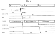
- FIGS. 43 and 44 are examples of motor control for prevention of unnecessary sudden braking and protection and coordination of control output.
- the control mode signals CNTL12-1, 2, 3 are output from the microcomputers constituting the ECUs 10-1, 2, and 3, and the abnormality detection result is OK / from the abnormality detection means.
- the microcomputer constituting the ECU 10-3 controls the transmission unit 300 (motor 321) and uses the control mode signal CNTL12-3 as the motor.
- the control mode (H) is output, and the abnormality detection means outputs OK (H) as the abnormality detection result OK / NG13-3.
- the non-motor control mode (L) is output as a control mode signal CNTL12-3 if the microcomputer can detect the failure. Even if the microcomputer cannot detect the failure, the abnormality detecting means outputs NG (L) as the abnormality detection result OK / NG13-3.
- the microcomputer constituting ECU 10-1 or 2 constantly monitors the control mode signal CNTL12-3 and the abnormality detection result OK / NG13-3, and the control mode signal CNTL12-3 is in the motor control mode (H) and the abnormality detection result OK / NG13.
- -3 OK (H)
- the originally assigned power (energy) source 100 or power (energy) source 200 is controlled (S1 in FIG. 44).
- S2 in FIG. 44 When a failure occurs in ECU 10-3 (S2 in FIG. 44) and the control mode signal CNTL12-3 becomes the non-motor control mode (L) or the abnormality detection result OK / NG13-3 becomes NG (L). Stops control of the originally assigned power (energy) source 100 or power (energy) source 200, and starts preparation for control of the transmission unit 300 (motor 321) (specifically, program download, initialization, etc.). (S3 in FIG. 44).
- the ECU 10-1 or 2 After the preparation for the transmission unit 300 (motor 321) control is completed, the ECU 10-1 or 2 starts the transmission unit 300 (motor 321) control, and the control mode signals CNTL12-1 and CNT are sent from the non-motor control mode (L) to the motor.
- the control mode (H) When the control mode (H) is set and the ECU 10-1 or 2 is normal, the abnormality detection function outputs OK (H) as the abnormality detection results OK / NG13-1 and 2 (S4 in FIG. 44).
- the SW2 that selects the control input to the converter 322 is controlled by the control mode signal CNTL12-3 and the abnormality detection result OK / NG13-3, or the control mode signal CNTL12-1, 2 and the abnormality detection result OK / NG13-1,2. , Both operate to select the output of the ECU which is H.
- the control output 11-3 is selected.
- the SW3 that opens and closes the phase output of the converter 322 and the SW4 that controls the power supply to the converter 322 are the control mode signal CNTL12-3 and the abnormality detection result OK / NG13-3 are both H, or the control mode signal CNTL12-1.
- 2 and the abnormality detection result OK / NG13-1 and 2 are both turned on when they are H, and the converter 322 can drive the output side motor 321.
- either ECU 10-3 or ECU 10-1 or 2 can drive the motor control mode, that is, the output side motor 321 and the abnormality detection result OK / NG is ON, that is, normal.
- the converter 322 can drive the output side motor 321 only when ing.
- the parallel hybrid drive system is also controlled in the same manner.
- the power converter 322 may be replaced with the solenoid driver 320, and the output side motor 321 may be replaced with the transmission 310 or the clutches CL1 and CL2 as shown in FIG.
- the control unit of the transmission unit that mixes the power (energy) from different power (energy) sources included in the hybrid drive system and transmits the energy to the drive wheels has a redundant configuration.
- the system as a whole can continue to operate.
- the transmission unit supplies energy to the drive wheels by the power (energy) from the other power (energy) source. The operation can be continued by controlling the transmission.
- control unit of the transmission unit which is a single point of failure of the entire system, with a function to continue operation in the event of a failure, control of the transmission unit can be continued even if the control unit of the transmission unit fails, and the entire system can be controlled. It is possible to continue the operation, that is, it becomes a fail operation.
Landscapes
- Engineering & Computer Science (AREA)
- Transportation (AREA)
- Mechanical Engineering (AREA)
- Combustion & Propulsion (AREA)
- Chemical & Material Sciences (AREA)
- Automation & Control Theory (AREA)
- Power Engineering (AREA)
- Human Computer Interaction (AREA)
- Life Sciences & Earth Sciences (AREA)
- Sustainable Energy (AREA)
- Sustainable Development (AREA)
- Health & Medical Sciences (AREA)
- Biomedical Technology (AREA)
- General Health & Medical Sciences (AREA)
- Electric Propulsion And Braking For Vehicles (AREA)
- Hybrid Electric Vehicles (AREA)
- Control Of Driving Devices And Active Controlling Of Vehicle (AREA)
Abstract
Description
前記伝達部へエネルギを入力する第2源と、前記第1源を制御する第2制御部と、前記第2源を制御する第3制御部と、を備え、前記第1制御部が故障した場合には、前記第2制御部もしくは前記第3制御部が前記伝達部を制御することを特徴とする。
図4に示すようにソレノイド311a、311bを冗長に持つ場合には、冗長化したECU10-3a、ECU10-3bがそれぞれソレノイド311a、311bを駆動することも可能である。なお、図示しないトランスミッション310内部の油圧回路によりORまたはセレクタ回路を構成することも可能である。
この場合にはモータ210による回生制動は可能であるため、制動時にはモータ210による回生制動と機械ブレーキを協調動作させて制動トルクを発生する。なお、安全のためには制御が単純な機械ブレーキによる制動が望ましい。
この方法によれば、ECU10-2がECU10-3の機能を代替できるようにすればよいので、切り替えスイッチ、配線(ネットワーク)や実行するプログラムファイルが前者よりも削減でき、コストも削減できる。
(インバータ)322に接続されている。電力変換器(インバータ)322は、電力変換器123、バッテリ220からの電力(直流)を3相交流電力に変換して出力側モータ(またはモータジェネレータ)321を駆動する。
Claims (15)
- 駆動輪にエネルギを伝達する伝達部と、
前記伝達部を制御する第1制御部と、
前記伝達部へエネルギを入力する第1源と、
前記伝達部へエネルギを入力する第2源と、
前記第1源を制御する第2制御部と、前記第2源を制御する第3制御部と、を備え、
前記第1制御部が故障した場合には、前記第2制御部もしくは前記第3制御部が前記伝達部を制御することを特徴とする車両制御システム。 - 前記第1源と前記第2源から前記伝達部へのエネルギ入力を制御する第4制御部を備え、
前記第4制御部は、前記第1制御部が故障した際には、第2もしくは第3制御部の機能切り替えの際に不要な制動が発生しないよう、前記伝達部へ駆動輪へのエネルギの伝達をOFFするよう指令を送信し、
前記第2制御部もしくは第3制御部は、機能が切り替わった後に前記伝達部へ駆動輪へのエネルギの伝達をONするよう指令を送信することを特徴とする請求項1に記載の車両制御システム。 - 前記第4制御部は、
前記第1源また前記は第2制御部が故障時には、前記第2源からのエネルギのみを前記伝達部へ入力する制御をし、
前記第2源また前記は第3制御部が故障時には、前記第1源からのエネルギのみを前記伝達部へ入力する制御をすることを特徴とする請求項2記載の車両制御システム。 - 前記伝達部はモータとインバータを有し、前記第1源はエンジン及び発電機を含み、前記第2源はバッテリであるシリーズハイブリッドであることを特徴とする請求項1乃至3の何れかに記載の車両制御システム。
- 前記第1の制御部が故障した際には、前記第2制御部で前記伝達部を制御し、
前記伝達部は、リレーをOFFすることで前記駆動輪へのエネルギの伝達のOFFを実現する請求項4に記載の車両制御システム - 前記第1の制御部は第1のマイコンにより実施され、前記第2の制御部はエンジンを制御する第2のマイコンと発電機を制御する第3のマイコンにより実施され、前記第1と第2と第3のマイコンを有する制御装置を備え、
前記第1のマイコンが故障した場合には、前記第3のマイコンで前記伝達部を制御する請求項5に記載の車両制御システム - 前記第1のマイコンと前記第3のマイコンは別の電源ICで駆動される等の共通原因故障対策が施されている請求項6に記載の車両制御システム
- 前記伝達部はトランスミッションであり、前記第1源はエンジンであり、前記第2源はバッテリ及びモータを含むパラレルハイブリッドであることを特徴とする請求項1乃至3の何れかに記載の車両制御システム。
- 前記第1の制御部が故障した際には、前記第3制御部で前記伝達部を制御し、
前記伝達部は、クラッチをOFFすることで前記駆動輪へのエネルギの伝達のOFFを実現する請求項8に記載の車両制御システム - 前記伝達部はモータであり、前記第1源はエンジン及び発電機を含み、前記第2源はバッテリであるシリーズパラレルハイブリッドであることを特徴とする請求項1乃至3の何れかに車両制御システム。
- 駆動輪にエネルギを伝達する伝達部と、前記伝達部を制御する第1制御部と、前記伝達部へエネルギを入力する第1源と、前記伝達部へエネルギを入力する第2源と、前記第1源を制御する第2制御部と、前記第2源を制御する第3制御部と、を備える車両に搭載される車両制御装置において、
前記第1制御部が故障した場合には、前記第2制御部もしくは前記第3制御部が前記伝達部を制御するように指令を送信する車両制御装置。 - 前記第1制御部が故障した際には、前記伝達部へ駆動輪へのエネルギの伝達をOFFするよう指令を送信する請求項1に記載の車両制御装置
- 前記第1源はエンジン及び発電機を含むシリーズハイブリッドもしくはシリーズパラレルハイブリッドの車両に搭載される場合には、
前記第1制御部が故障した場合には、前記第2制御部に対して前記伝達部を制御するように指令を送信する請求項12に記載の車両制御装置 - 前記伝達部はトランスミッションであり、前記第1源はエンジンであり、前記第2源はバッテリ及びモータを含むパラレルハイブリッドの車両に搭載される場合には、
前記第1制御部が故障した場合には、前記第3制御部に対して前記伝達部を制御するように指令を送信する請求項12に記載の車両制御装置 - 前記第1源と前記第2源から前記伝達部へのエネルギ入力を制御し、
前記第1制御部が故障した場合には、前記第2源のみで前記伝達部へエネルギ入力するように制御する請求項11乃至14の何れかに記載の車両制御装置
Priority Applications (2)
| Application Number | Priority Date | Filing Date | Title |
|---|---|---|---|
| US17/777,872 US12275392B2 (en) | 2020-03-27 | 2021-01-15 | Vehicle control device |
| CN202180007112.8A CN114787009B (zh) | 2020-03-27 | 2021-01-15 | 车辆控制装置 |
Applications Claiming Priority (2)
| Application Number | Priority Date | Filing Date | Title |
|---|---|---|---|
| JP2020057070A JP7316245B2 (ja) | 2020-03-27 | 2020-03-27 | 車両制御システム及び車両制御装置 |
| JP2020-057070 | 2020-03-27 |
Publications (1)
| Publication Number | Publication Date |
|---|---|
| WO2021192532A1 true WO2021192532A1 (ja) | 2021-09-30 |
Family
ID=77890078
Family Applications (1)
| Application Number | Title | Priority Date | Filing Date |
|---|---|---|---|
| PCT/JP2021/001190 Ceased WO2021192532A1 (ja) | 2020-03-27 | 2021-01-15 | 車両制御装置 |
Country Status (4)
| Country | Link |
|---|---|
| US (1) | US12275392B2 (ja) |
| JP (1) | JP7316245B2 (ja) |
| CN (1) | CN114787009B (ja) |
| WO (1) | WO2021192532A1 (ja) |
Cited By (1)
| Publication number | Priority date | Publication date | Assignee | Title |
|---|---|---|---|---|
| GB2619587A (en) * | 2022-03-30 | 2023-12-13 | Porsche Ag | Modular system |
Families Citing this family (2)
| Publication number | Priority date | Publication date | Assignee | Title |
|---|---|---|---|---|
| KR20220147992A (ko) * | 2021-04-28 | 2022-11-04 | 현대자동차주식회사 | 차량 전원 제어 장치 및 방법 |
| JP7721380B2 (ja) | 2021-09-22 | 2025-08-12 | 株式会社ブリヂストン | タイヤ |
Citations (6)
| Publication number | Priority date | Publication date | Assignee | Title |
|---|---|---|---|---|
| JP2002221075A (ja) * | 2001-01-25 | 2002-08-09 | Denso Corp | 車両統合制御におけるフェイルセーフシステム |
| JP2008302754A (ja) * | 2007-06-06 | 2008-12-18 | Daihatsu Motor Co Ltd | ハイブリッド自動車の制御装置 |
| WO2016156204A1 (en) * | 2015-03-30 | 2016-10-06 | Volvo Truck Corporation | Method and arrangement for providing redundancy in a vehicle electrical control system |
| WO2018229930A1 (ja) * | 2017-06-15 | 2018-12-20 | 株式会社日立製作所 | コントローラ |
| JP2019043427A (ja) * | 2017-09-05 | 2019-03-22 | トヨタ自動車株式会社 | ハイブリッド車両 |
| JP2019073204A (ja) * | 2017-10-18 | 2019-05-16 | トヨタ自動車株式会社 | ハイブリッド自動車 |
Family Cites Families (11)
| Publication number | Priority date | Publication date | Assignee | Title |
|---|---|---|---|---|
| JP4341631B2 (ja) * | 2006-01-31 | 2009-10-07 | トヨタ自動車株式会社 | 車両の異常判定装置 |
| US20130297125A1 (en) * | 2012-05-07 | 2013-11-07 | Ford Global Technologies, Llc | Torque filling and torque coordination during transients in a hybrid vehicle |
| JP6045409B2 (ja) * | 2013-03-13 | 2016-12-14 | 日立オートモティブシステムズ株式会社 | オイル供給装置 |
| US10185315B2 (en) * | 2014-02-25 | 2019-01-22 | Hitachi Automotive Systems, Ltd. | Motor control system and motor control method |
| JP6606453B2 (ja) * | 2016-03-29 | 2019-11-13 | 株式会社Subaru | ハイブリッド車両の制御システム及びモータ制御ユニット |
| JP2018016107A (ja) | 2016-07-25 | 2018-02-01 | パナソニックIpマネジメント株式会社 | 監視用ecuおよび車両 |
| JP6341238B2 (ja) * | 2016-07-29 | 2018-06-13 | トヨタ自動車株式会社 | 自動車 |
| JP7115913B2 (ja) * | 2018-06-14 | 2022-08-09 | 株式会社Subaru | 車両の制御装置及び制御方法 |
| DE102018215605A1 (de) * | 2018-09-13 | 2020-03-19 | Ford Global Technologies, Llc | Bordnetz für ein Kraftfahrzeug |
| JP7155933B2 (ja) * | 2018-11-21 | 2022-10-19 | トヨタ自動車株式会社 | プラグインハイブリッド車およびその制御方法 |
| JP7238723B2 (ja) * | 2019-10-11 | 2023-03-14 | トヨタ自動車株式会社 | 車両の制御装置 |
-
2020
- 2020-03-27 JP JP2020057070A patent/JP7316245B2/ja active Active
-
2021
- 2021-01-15 US US17/777,872 patent/US12275392B2/en active Active
- 2021-01-15 CN CN202180007112.8A patent/CN114787009B/zh active Active
- 2021-01-15 WO PCT/JP2021/001190 patent/WO2021192532A1/ja not_active Ceased
Patent Citations (6)
| Publication number | Priority date | Publication date | Assignee | Title |
|---|---|---|---|---|
| JP2002221075A (ja) * | 2001-01-25 | 2002-08-09 | Denso Corp | 車両統合制御におけるフェイルセーフシステム |
| JP2008302754A (ja) * | 2007-06-06 | 2008-12-18 | Daihatsu Motor Co Ltd | ハイブリッド自動車の制御装置 |
| WO2016156204A1 (en) * | 2015-03-30 | 2016-10-06 | Volvo Truck Corporation | Method and arrangement for providing redundancy in a vehicle electrical control system |
| WO2018229930A1 (ja) * | 2017-06-15 | 2018-12-20 | 株式会社日立製作所 | コントローラ |
| JP2019043427A (ja) * | 2017-09-05 | 2019-03-22 | トヨタ自動車株式会社 | ハイブリッド車両 |
| JP2019073204A (ja) * | 2017-10-18 | 2019-05-16 | トヨタ自動車株式会社 | ハイブリッド自動車 |
Cited By (2)
| Publication number | Priority date | Publication date | Assignee | Title |
|---|---|---|---|---|
| GB2619587A (en) * | 2022-03-30 | 2023-12-13 | Porsche Ag | Modular system |
| GB2619587B (en) * | 2022-03-30 | 2024-06-05 | Porsche Ag | Modular system |
Also Published As
| Publication number | Publication date |
|---|---|
| CN114787009A (zh) | 2022-07-22 |
| JP7316245B2 (ja) | 2023-07-27 |
| US20230076114A1 (en) | 2023-03-09 |
| US12275392B2 (en) | 2025-04-15 |
| CN114787009B (zh) | 2025-08-08 |
| JP2021154870A (ja) | 2021-10-07 |
Similar Documents
| Publication | Publication Date | Title |
|---|---|---|
| US6234930B1 (en) | Transmission and vehicle using same | |
| JP7316245B2 (ja) | 車両制御システム及び車両制御装置 | |
| JP6694325B2 (ja) | 車両制御システム | |
| US6724100B1 (en) | HEV charger/generator unit | |
| JPH11151942A (ja) | ハイブリッド車両の非常駆動装置 | |
| CN110893822A (zh) | 一种用于机动车辆的车载电网 | |
| JP7240275B2 (ja) | 車両制御装置並びに車両制御システム | |
| US6636009B2 (en) | Fault-tolerant electromechanical actuating device | |
| KR20190080260A (ko) | 병렬형 하이브리드 차량의 페일 세이프 방법 | |
| JP4162781B2 (ja) | ハイブリッド車の制御装置 | |
| US11623543B2 (en) | Method for operating an on-board electrical network of a motor vehicle | |
| CN121734270B (zh) | 动力域控制器和车辆 | |
| JP4162782B2 (ja) | ハイブリッド車の制御装置 | |
| CN114174173B (zh) | 包括辅助机械驱动系统的飞行器混合动力推进链 | |
| JP6365072B2 (ja) | ハイブリッド車両システム | |
| CN113353058A (zh) | 混合动力汽车的车辆行驶控制系统及车辆行驶控制方法 | |
| WO2024043023A1 (ja) | 電力供給網、電動車両及び電力変換装置 | |
| JP4096677B2 (ja) | ハイブリッド電気自動車の電源回路システム | |
| KR102869230B1 (ko) | 하이브리드 차량의 후진 주행 제어 방법 | |
| JP3463521B2 (ja) | 電気自動車用駆動制御装置 | |
| KR20110049157A (ko) | 하이브리드 차량의 페일 세이프 제어방법 | |
| JP2023059691A (ja) | ハイブリッド車両の電子制御装置 | |
| CN118617974A (zh) | 动力总成、控制方法和车辆 | |
| WO2025173503A1 (ja) | 小型電動車両 | |
| KR20070023116A (ko) | 하이브리드 변속기용 모터 고장 제어장치 및 그 제어방법 |
Legal Events
| Date | Code | Title | Description |
|---|---|---|---|
| 121 | Ep: the epo has been informed by wipo that ep was designated in this application |
Ref document number: 21776905 Country of ref document: EP Kind code of ref document: A1 |
|
| NENP | Non-entry into the national phase |
Ref country code: DE |
|
| 122 | Ep: pct application non-entry in european phase |
Ref document number: 21776905 Country of ref document: EP Kind code of ref document: A1 |
|
| WWG | Wipo information: grant in national office |
Ref document number: 17777872 Country of ref document: US |
|
| WWG | Wipo information: grant in national office |
Ref document number: 202180007112.8 Country of ref document: CN |