US11623543B2 - Method for operating an on-board electrical network of a motor vehicle - Google Patents
Method for operating an on-board electrical network of a motor vehicle Download PDFInfo
- Publication number
- US11623543B2 US11623543B2 US17/024,218 US202017024218A US11623543B2 US 11623543 B2 US11623543 B2 US 11623543B2 US 202017024218 A US202017024218 A US 202017024218A US 11623543 B2 US11623543 B2 US 11623543B2
- Authority
- US
- United States
- Prior art keywords
- main battery
- voltage circuit
- state
- electrical network
- board electrical
- Prior art date
- Legal status (The legal status is an assumption and is not a legal conclusion. Google has not performed a legal analysis and makes no representation as to the accuracy of the status listed.)
- Active, expires
Links
Images


Classifications
-
- B—PERFORMING OPERATIONS; TRANSPORTING
- B60—VEHICLES IN GENERAL
- B60R—VEHICLES, VEHICLE FITTINGS, OR VEHICLE PARTS, NOT OTHERWISE PROVIDED FOR
- B60R16/00—Electric or fluid circuits specially adapted for vehicles and not otherwise provided for; Arrangement of elements of electric or fluid circuits specially adapted for vehicles and not otherwise provided for
- B60R16/02—Electric or fluid circuits specially adapted for vehicles and not otherwise provided for; Arrangement of elements of electric or fluid circuits specially adapted for vehicles and not otherwise provided for electric constitutive elements
- B60R16/03—Electric or fluid circuits specially adapted for vehicles and not otherwise provided for; Arrangement of elements of electric or fluid circuits specially adapted for vehicles and not otherwise provided for electric constitutive elements for supply of electrical power to vehicle subsystems or for
- B60R16/033—Electric or fluid circuits specially adapted for vehicles and not otherwise provided for; Arrangement of elements of electric or fluid circuits specially adapted for vehicles and not otherwise provided for electric constitutive elements for supply of electrical power to vehicle subsystems or for characterised by the use of electrical cells or batteries
-
- B—PERFORMING OPERATIONS; TRANSPORTING
- B60—VEHICLES IN GENERAL
- B60L—PROPULSION OF ELECTRICALLY-PROPELLED VEHICLES; SUPPLYING ELECTRIC POWER FOR AUXILIARY EQUIPMENT OF ELECTRICALLY-PROPELLED VEHICLES; ELECTRODYNAMIC BRAKE SYSTEMS FOR VEHICLES IN GENERAL; MAGNETIC SUSPENSION OR LEVITATION FOR VEHICLES; MONITORING OPERATING VARIABLES OF ELECTRICALLY-PROPELLED VEHICLES; ELECTRIC SAFETY DEVICES FOR ELECTRICALLY-PROPELLED VEHICLES
- B60L58/00—Methods or circuit arrangements for monitoring or controlling batteries or fuel cells, specially adapted for electric vehicles
- B60L58/10—Methods or circuit arrangements for monitoring or controlling batteries or fuel cells, specially adapted for electric vehicles for monitoring or controlling batteries
- B60L58/18—Methods or circuit arrangements for monitoring or controlling batteries or fuel cells, specially adapted for electric vehicles for monitoring or controlling batteries of two or more battery modules
- B60L58/20—Methods or circuit arrangements for monitoring or controlling batteries or fuel cells, specially adapted for electric vehicles for monitoring or controlling batteries of two or more battery modules having different nominal voltages
-
- B—PERFORMING OPERATIONS; TRANSPORTING
- B60—VEHICLES IN GENERAL
- B60L—PROPULSION OF ELECTRICALLY-PROPELLED VEHICLES; SUPPLYING ELECTRIC POWER FOR AUXILIARY EQUIPMENT OF ELECTRICALLY-PROPELLED VEHICLES; ELECTRODYNAMIC BRAKE SYSTEMS FOR VEHICLES IN GENERAL; MAGNETIC SUSPENSION OR LEVITATION FOR VEHICLES; MONITORING OPERATING VARIABLES OF ELECTRICALLY-PROPELLED VEHICLES; ELECTRIC SAFETY DEVICES FOR ELECTRICALLY-PROPELLED VEHICLES
- B60L3/00—Electric devices on electrically-propelled vehicles for safety purposes; Monitoring operating variables, e.g. speed, deceleration or energy consumption
- B60L3/0023—Detecting, eliminating, remedying or compensating for drive train abnormalities, e.g. failures within the drive train
- B60L3/0046—Detecting, eliminating, remedying or compensating for drive train abnormalities, e.g. failures within the drive train relating to electric energy storage systems, e.g. batteries or capacitors
-
- B—PERFORMING OPERATIONS; TRANSPORTING
- B60—VEHICLES IN GENERAL
- B60L—PROPULSION OF ELECTRICALLY-PROPELLED VEHICLES; SUPPLYING ELECTRIC POWER FOR AUXILIARY EQUIPMENT OF ELECTRICALLY-PROPELLED VEHICLES; ELECTRODYNAMIC BRAKE SYSTEMS FOR VEHICLES IN GENERAL; MAGNETIC SUSPENSION OR LEVITATION FOR VEHICLES; MONITORING OPERATING VARIABLES OF ELECTRICALLY-PROPELLED VEHICLES; ELECTRIC SAFETY DEVICES FOR ELECTRICALLY-PROPELLED VEHICLES
- B60L3/00—Electric devices on electrically-propelled vehicles for safety purposes; Monitoring operating variables, e.g. speed, deceleration or energy consumption
- B60L3/0092—Electric devices on electrically-propelled vehicles for safety purposes; Monitoring operating variables, e.g. speed, deceleration or energy consumption with use of redundant elements for safety purposes
-
- B—PERFORMING OPERATIONS; TRANSPORTING
- B60—VEHICLES IN GENERAL
- B60R—VEHICLES, VEHICLE FITTINGS, OR VEHICLE PARTS, NOT OTHERWISE PROVIDED FOR
- B60R16/00—Electric or fluid circuits specially adapted for vehicles and not otherwise provided for; Arrangement of elements of electric or fluid circuits specially adapted for vehicles and not otherwise provided for
- B60R16/02—Electric or fluid circuits specially adapted for vehicles and not otherwise provided for; Arrangement of elements of electric or fluid circuits specially adapted for vehicles and not otherwise provided for electric constitutive elements
- B60R16/03—Electric or fluid circuits specially adapted for vehicles and not otherwise provided for; Arrangement of elements of electric or fluid circuits specially adapted for vehicles and not otherwise provided for electric constitutive elements for supply of electrical power to vehicle subsystems or for
-
- F—MECHANICAL ENGINEERING; LIGHTING; HEATING; WEAPONS; BLASTING
- F16—ENGINEERING ELEMENTS AND UNITS; GENERAL MEASURES FOR PRODUCING AND MAINTAINING EFFECTIVE FUNCTIONING OF MACHINES OR INSTALLATIONS; THERMAL INSULATION IN GENERAL
- F16H—GEARING
- F16H61/00—Control functions within control units of change-speed- or reversing-gearings for conveying rotary motion ; Control of exclusively fluid gearing, friction gearing, gearings with endless flexible members or other particular types of gearing
- F16H61/02—Control functions within control units of change-speed- or reversing-gearings for conveying rotary motion ; Control of exclusively fluid gearing, friction gearing, gearings with endless flexible members or other particular types of gearing characterised by the signals used
- F16H61/0202—Control functions within control units of change-speed- or reversing-gearings for conveying rotary motion ; Control of exclusively fluid gearing, friction gearing, gearings with endless flexible members or other particular types of gearing characterised by the signals used the signals being electric
- F16H61/0204—Control functions within control units of change-speed- or reversing-gearings for conveying rotary motion ; Control of exclusively fluid gearing, friction gearing, gearings with endless flexible members or other particular types of gearing characterised by the signals used the signals being electric for gearshift control, e.g. control functions for performing shifting or generation of shift signal
-
- F—MECHANICAL ENGINEERING; LIGHTING; HEATING; WEAPONS; BLASTING
- F16—ENGINEERING ELEMENTS AND UNITS; GENERAL MEASURES FOR PRODUCING AND MAINTAINING EFFECTIVE FUNCTIONING OF MACHINES OR INSTALLATIONS; THERMAL INSULATION IN GENERAL
- F16H—GEARING
- F16H61/00—Control functions within control units of change-speed- or reversing-gearings for conveying rotary motion ; Control of exclusively fluid gearing, friction gearing, gearings with endless flexible members or other particular types of gearing
- F16H61/12—Detecting malfunction or potential malfunction, e.g. fail safe; Circumventing or fixing failures
-
- F—MECHANICAL ENGINEERING; LIGHTING; HEATING; WEAPONS; BLASTING
- F16—ENGINEERING ELEMENTS AND UNITS; GENERAL MEASURES FOR PRODUCING AND MAINTAINING EFFECTIVE FUNCTIONING OF MACHINES OR INSTALLATIONS; THERMAL INSULATION IN GENERAL
- F16H—GEARING
- F16H63/00—Control outputs from the control unit to change-speed- or reversing-gearings for conveying rotary motion or to other devices than the final output mechanism
- F16H63/40—Control outputs from the control unit to change-speed- or reversing-gearings for conveying rotary motion or to other devices than the final output mechanism comprising signals other than signals for actuating the final output mechanisms
- F16H63/48—Signals to a parking brake or parking lock; Control of parking locks or brakes being part of the transmission
-
- H—ELECTRICITY
- H02—GENERATION; CONVERSION OR DISTRIBUTION OF ELECTRIC POWER
- H02J—CIRCUIT ARRANGEMENTS OR SYSTEMS FOR SUPPLYING OR DISTRIBUTING ELECTRIC POWER; SYSTEMS FOR STORING ELECTRIC ENERGY
- H02J1/00—Circuit arrangements for dc mains or dc distribution networks
- H02J1/10—Parallel operation of dc sources
- H02J1/109—Scheduling or re-scheduling the operation of the DC sources in a particular order, e.g. connecting or disconnecting the sources in sequential, alternating or in subsets, to meet a given demand
-
- H—ELECTRICITY
- H02—GENERATION; CONVERSION OR DISTRIBUTION OF ELECTRIC POWER
- H02J—CIRCUIT ARRANGEMENTS OR SYSTEMS FOR SUPPLYING OR DISTRIBUTING ELECTRIC POWER; SYSTEMS FOR STORING ELECTRIC ENERGY
- H02J7/00—Circuit arrangements for charging or depolarising batteries or for supplying loads from batteries
- H02J7/0029—Circuit arrangements for charging or depolarising batteries or for supplying loads from batteries with safety or protection devices or circuits
-
- F—MECHANICAL ENGINEERING; LIGHTING; HEATING; WEAPONS; BLASTING
- F16—ENGINEERING ELEMENTS AND UNITS; GENERAL MEASURES FOR PRODUCING AND MAINTAINING EFFECTIVE FUNCTIONING OF MACHINES OR INSTALLATIONS; THERMAL INSULATION IN GENERAL
- F16H—GEARING
- F16H61/00—Control functions within control units of change-speed- or reversing-gearings for conveying rotary motion ; Control of exclusively fluid gearing, friction gearing, gearings with endless flexible members or other particular types of gearing
- F16H61/12—Detecting malfunction or potential malfunction, e.g. fail safe; Circumventing or fixing failures
- F16H2061/122—Avoiding failures by using redundant parts
-
- F—MECHANICAL ENGINEERING; LIGHTING; HEATING; WEAPONS; BLASTING
- F16—ENGINEERING ELEMENTS AND UNITS; GENERAL MEASURES FOR PRODUCING AND MAINTAINING EFFECTIVE FUNCTIONING OF MACHINES OR INSTALLATIONS; THERMAL INSULATION IN GENERAL
- F16H—GEARING
- F16H61/00—Control functions within control units of change-speed- or reversing-gearings for conveying rotary motion ; Control of exclusively fluid gearing, friction gearing, gearings with endless flexible members or other particular types of gearing
- F16H61/12—Detecting malfunction or potential malfunction, e.g. fail safe; Circumventing or fixing failures
- F16H2061/1256—Detecting malfunction or potential malfunction, e.g. fail safe; Circumventing or fixing failures characterised by the parts or units where malfunctioning was assumed or detected
- F16H2061/1292—Detecting malfunction or potential malfunction, e.g. fail safe; Circumventing or fixing failures characterised by the parts or units where malfunctioning was assumed or detected the failing part is the power supply, e.g. the electric power supply
-
- Y—GENERAL TAGGING OF NEW TECHNOLOGICAL DEVELOPMENTS; GENERAL TAGGING OF CROSS-SECTIONAL TECHNOLOGIES SPANNING OVER SEVERAL SECTIONS OF THE IPC; TECHNICAL SUBJECTS COVERED BY FORMER USPC CROSS-REFERENCE ART COLLECTIONS [XRACs] AND DIGESTS
- Y02—TECHNOLOGIES OR APPLICATIONS FOR MITIGATION OR ADAPTATION AGAINST CLIMATE CHANGE
- Y02T—CLIMATE CHANGE MITIGATION TECHNOLOGIES RELATED TO TRANSPORTATION
- Y02T10/00—Road transport of goods or passengers
- Y02T10/60—Other road transportation technologies with climate change mitigation effect
- Y02T10/70—Energy storage systems for electromobility, e.g. batteries
Definitions
- the invention relates to a method for operating an on-board electrical network of a motor vehicle.
- the invention also relates to a computer program product, an on-board electrical network for a motor vehicle, and a motor vehicle having such an on-board electrical network.
- An on-board electrical network is understood to mean the totality of all electrical components in a motor vehicle, such as a car.
- a 12-Volt on-board electrical network can now barely cover the power consumption required by a modern motor vehicle for its comfort systems.
- the “static” consumers almost completely exhaust the alternator, which delivers up to 3 kW of power, especially at low temperatures.
- the battery power is not sufficient. Therefore, a second partial on-board electrical network with a voltage of 48 Volts is added, which complements the 12-Volt onboard network.
- An on-board electrical network with an operating voltage of 48 Volts also offers the possibility of implementing a simpler hybridization quickly and cost-effectively and of keeping harmful emissions below statutory limits by partial electrification of the powertrain of the motor vehicle.
- a uni- or bidirectional DC/DC converter supplies the 12-Volt on-board network from the 48-Volt onboard network.
- the powertrain has an electric motor, such as a belt-driven starter generator (BiSG) or a transmission-integrated motor generator (TiMG), an inverter, a DC/DC converter and a 48-Volt battery.
- a belt-driven starter generator BiSG
- a transmission-integrated motor generator TiMG
- an inverter inverter
- DC/DC converter DC/DC converter
- 48-Volt battery 48-Volt battery
- a 48-Volt on-board electrical network can be used to operate an electric motor as a motor with up to 15 kW.
- this requires an engine restart under all driving conditions, even at low speeds.
- a second battery is required in combination with a 12 V output of the DC/DC converter in order to stabilize the on-board supply voltage in particular when starting up the internal combustion engine.
- a 12-Volt output of the DC/DC converter cannot be regarded as stable.
- Shift-by-Wire systems or Park-by-Wire systems Special requirements on operational safety are placed by Shift-by-Wire systems or Park-by-Wire systems, in which actuating signals are only transmitted electrically. Some system redundancy is therefore required in the on-board network voltage, so that for example a motor vehicle can be safely parked with a parking system or an electric parking brake in the event of a particular fault in the on-board electrical network.
- the 48-Volt battery can be a lithium-ion battery.
- Such lithium-ion batteries do not deliver sufficient electrical current at low temperatures to start the engine. Therefore, a conventional starter is supplied with operating power from a 12-Volt lead-acid battery.
- the object of the invention is achieved by a method for operating an on-board electrical network of a motor vehicle, having a first voltage circuit and a second voltage circuit, the first voltage circuit having a first operating voltage which is higher than a second operating voltage in the second voltage circuit, the first voltage circuit being connected to the second voltage circuit via a DC/DC converter, the first voltage circuit having a battery and the second voltage circuit having at least one main battery, wherein the first main battery and the second main battery have essentially the same capacity, and wherein by means of a switch assembly, components of the motor vehicle are supplied with electrical energy from the first main battery and/or the second main battery.
- a capacity that is essentially the same means that the respective capacities of the first and second main batteries differ by manufacturing-related tolerances, for example, by 5% or 10%.
- the first and second main batteries can be identical in design.
- the first and second main batteries can be combined into one component and can be accommodated in a common housing, for example.
- a first of the two main batteries is used to supply all components of the on-board network with electrical operating energy, while the second of the two main batteries is used also to supply all components of the on-board network with electrical operating energy and additionally to provide fault management (FMEM, also known as failure mode management) or system redundancy in the event of a failure of the first main battery.
- FMEM fault management
- failure mode management failure mode management
- the fact that the first main battery and the second main battery have essentially the same capacity prevents overheating of the main battery that has the lower capacity. Measures to prevent overheating of the main battery with the smaller capacity can thus be omitted. In addition, there is no need to provide controlled charging and discharging of the lower capacity if one battery is smaller.
- a significant advantage is that the capacity of the first and second main batteries is equal to the sum of the total capacity of a single main battery.
- the invention divides the total capacity of a single main battery into two functional halves as described above, respectively into a first and a second main battery. A smaller backup battery for a single low-capacity main battery is no longer required. This invention not only improves the robustness, but also decreases the installation space and reduces the additional costs of a smaller replacement battery.
- the switch assembly has a 3-way changeover switch.
- a 3-way changeover switch is a switch in which an input is connected to one of three outputs, but a connection is always provided between the input and one of the three outputs. In other words, there is no open switching state that would disconnect the input from all outputs at the same time. This ensures that there is always a connection between the input and one of the outputs, and thus a supply of electrical operating energy is also guaranteed. In this way, a particularly reliable on-board network with a simple structure can be provided. The input is always connected to the entire on-board network at the same time as the first main battery.
- the switch assembly has a 2-way changeover switch and an isolating switch.
- the isolating switch differs from the 2-way and 3-way changeover switches in that it has an open switching state that disconnects the input from the output.
- This isolating switch performs the same function as the three functions of the 3-way changeover switch. This means that a particularly reliable on-board network can be provided with a simple, alternative design.
- a fail-safe operating mode in a fail-safe operating mode (State R) at least one of the components is a transmission control unit and/or an integrated hybrid controller and/or a gear-selection control unit.
- the main battery of the two that supplies these components is thus designed to supply all components of the on-board network with electrical operating energy and to provide the fault management. This ensures that even in the event of a fault, the transmission control unit and/or the integrated hybrid controller and/or the gear-selection control unit, such as a shift-by-wire and park-by-wire control unit, are supplied with operating energy by the fault management system and therefore function correctly.
- This output when switched, separates the first main battery from the second, the first main battery supplying the ABS system with electrical voltage. This is done independently in comparison to the second main battery, which is connected to the park-by-wire/shift-by-wire. This ensures that the park/shift-by-wire and the ABS system have a separate, guaranteed, supply of electrical operating energy.
- the first main battery and the second main battery together supply at least one of the components of the on-board network with electrical operating energy via a fuse.
- the total capacity of the two main batteries is therefore used. If the fuse opens, the first main battery is disconnected from the second main battery with a separate supply of electrical energy compared to the operating mode which can be selected externally.
- the first main battery and the second main battery together supply at least one of the components of the on-board network with electrical operating energy, bypassing the fuse, and are disconnected from the rest of the on-board network.
- Bypassing the fuse by, for example by enabling an electrically conductive bypass, ensures that the fuse is not overloaded and thereby tripped when the internal combustion engine is started. This further increases the operational safety.
- the invention also relates to a computer program product, an on-board electrical network for a motor vehicle, and a motor vehicle having such an on-board network.
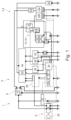
- FIG. 1 shows a schematic representation of an on-board electrical network of a motor vehicle according to a first exemplary embodiment.
- FIG. 2 shows a schematic representation of an on-board electrical network of a motor vehicle according to a second exemplary embodiment.
- FIG. 3 shows a schematic representation of an on-board electrical network of a motor vehicle according to a third exemplary embodiment.
- FIG. 4 shows a schematic representation of an on-board electrical network of a motor vehicle according to a fourth exemplary embodiment.
- FIG. 1 to explain a first exemplary embodiment.
- FIG. 1 shows an on-board electrical network 4 of a motor vehicle 2 , such as a car.
- the motor vehicle 2 in the present exemplary embodiment has a powertrain 6 .
- This powertrain 6 comprises all the components of the motor vehicle 2 that generate the power to drive the motor vehicle 2 and transfer it onto the road.
- the powertrain 6 is designed as a mild hybrid powertrain.
- the motor vehicle 2 has a hybrid drive and is implemented as a hybrid electric vehicle.
- a hybrid drive is understood to mean a combination of an internal combustion engine (not shown) and an electric motor 28 for the motor vehicle drive.
- the internal combustion engine in the present exemplary embodiment is a petrol engine. In normal operation the petrol engine is operated with an oxygen excess ( ⁇ >1). By way of deviation from this, the internal combustion engine can also be designed as a Diesel engine in lean-burn mode to increase the engine efficiency.
- the electric motor 28 is an electrical rotary motor with a rotor and a stator, which can be operated both as a motor, i.e. as a partial traction motor, and as a generator for energy recuperation.
- the electric motor 28 can be designed, for example, as a DC motor, an AC motor, a synchronous motor, an asynchronous motor, a brushless electric motor or as a combination of these motor types.
- the electric motor 28 of the powertrain 6 implemented as a mild hybrid powertrain delivers up to 15 kW per tonne of vehicle weight. In operation the electric motor 28 only assists the internal combustion engine to increase power. A purely electric driving is only possible to a limited extent, if at all.
- the internal combustion engine and the electric motor 28 can work together in different ways: in parallel (the internal combustion engine and the electric motor 28 act on the moving part at the same time), serially (only one of the motors acts directly on the moving part, while the other motor provides power which is converted and fed to the directly acting motor), or as a power-split hybrid.
- the powertrain 6 implemented as a mild hybrid powertrain in the present exemplary embodiment is implemented as a parallel hybrid powertrain.
- the on-board electrical network 4 has a first voltage circuit I and a second voltage circuit II.
- the first voltage circuit operates at a first operating voltage which is higher than a second operating voltage in the second voltage circuit II.
- the first operating voltage is 48 volts and the second operating voltage is 12 volts.
- the first voltage circuit I is connected to the second voltage circuit II via a DC/DC converter 8 .
- the DC/DC converter 8 in the present exemplary embodiment is designed for bidirectional voltage conversion, so for both stepping up and stepping down an electrical voltage.
- the first voltage circuit I in the present exemplary embodiment comprises a battery 10 and an inverter 26 .
- the battery 10 in this exemplary embodiment is a lithium-ion battery which is electrically conductively connected to the DC/DC converter 8 .
- the inverter 26 is a bi-directional inverter. In the generator mode of the electric motor 28 the inverter 26 converts an electrical AC voltage into an electrical DC voltage, and vice versa in the case of an application as an electric motor, converting an electrical DC voltage into an electrical alternating voltage. For this purpose the inverter 26 is electrically conductively connected on the input side to the electric motor 28 . The inverter 26 is additionally electrically conductively connected on the output side to the DC/DC converter 8 .
- the second voltage circuit II in the present exemplary embodiment comprises as an essential component a first main battery 12 a and a second main battery 12 b of essentially the same capacity, a switch assembly 14 with a 3-way changeover switch 16 in the present exemplary embodiment, a transmission control unit (TCM) 20 , an integrated hybrid controller (HFM) 22 , e.g. integrated in a transmission control unit, and a gear-selection control unit (GSM) 24 for gear selection between Drive/Neutral/Reverse and Park, which allows the electrically actuated parking lock/immobilizer to be engaged in the transmission and thereby secure the vehicle, and a starter 30 .
- the starter 30 in this exemplary embodiment is a conventional 12V starter.
- the gear-selection control unit 24 is actuated by the driver who thus expresses a desire to engage Drive/Neutral/Reverse or Park.
- the gear-selection control unit 24 then sends an equivalent signal to the transmission control unit 20 , which executes this command.
- ABS/EPB system 32 a powertrain control unit (PCM) 34 , an EPAS system 36 , a gateway module (GWM) 38 , an on-board network control unit (BCM) 40 , an infotainment system (IPC) 42 , a fuse assembly 44 , a first fuse 46 , a second fuse 48 , a third fuse 50 , a fourth fuse 52 , an EPB/ABS fuse 54 , a first battery management system 56 a assigned to the first main battery 12 a and a second battery management system 56 b assigned to the second main battery 12 b , as well as a third battery management system 56 c assigned to the battery 10 .
- PCM powertrain control unit
- GWM gateway module
- IPC infotainment system
- the components listed may have hardware and/or software components for their tasks and functions described below.
- the 3-way changeover switch 16 has an input-side connection E and three output-side connections L, M, R.
- the 3-way changeover switch 16 can be activated in such a way that the 3-way changeover switch 16 electrically connects the input-side connection E to the output-side connection L or the output-side connection M or the output-side connection R.
- the on-board network 4 is in a fail-safe operating mode (State R).
- the transmission control unit 20 and/or an integrated hybrid controller 22 are now supplied with electrical operating energy from the second main battery 12 b only and the first main battery 12 a is disconnected from the on-board network 4 .
- the ABS/EPB system 32 is connected to the first main battery 12 a and the transmission control unit (TCM) 20 , an integrated hybrid controller (HFM) 22 , e.g. integrated in a transmission control unit, and a gear selection control unit (GSM) 24 for gear selection between Drive/Neutral/Reverse and Park are connected independently of each other to the second main battery 12 b , thus providing a system redundancy for vehicle safety when stationary.
- TCM transmission control unit
- HARM integrated hybrid controller
- GSM gear selection control unit
- the on-board network 4 is in a standby mode (State L).
- the transmission control unit 20 and/or an integrated hybrid controller 22 as well as the gear-selection control unit 24 are now supplied with electrical operating energy from the first main battery 12 a and the second main battery 12 b via the fuse 50 and via the fuse 46 or fuse 48 respectively.
- further components of the on-board network 4 can be supplied with electrical operating energy from the first main battery 12 a and the second main battery 12 b.
- the on-board network 4 is in a starting mode (State M).
- State M a starting mode
- An electrically conductive bypass is now formed, which allows the fuse 50 to be bypassed.
- the transmission control unit 20 and/or an integrated hybrid controller 22 and the gear-selection control unit 24 can be supplied with electrical operating energy from the first main battery 12 a and the second main battery 12 b together in a parallel connection, bypassing the fuse 50 , and simultaneously disconnected from the rest of the on-board network 4 .
- the transmission control unit 20 and/or an integrated hybrid controller 22 when a fault is detected in the first main battery 12 a , upon being activated by the on-board network control unit 40 by providing appropriate activation signals, the transmission control unit 20 and/or an integrated hybrid controller 22 causes the 3-way changeover switch 16 to connect the input-side connection E to the output-side connection R in an electrically conducting manner, so that the on-board network 4 is in the fail-safe operating mode (State R).
- the powertrain control unit 34 by providing appropriate control signals, causes the 3-way changeover switch 16 to connect the input-side connection E to the output-side connection L in an electrically conducting manner, so that the on-board network 4 is in a standby mode (State L), and the 3-way changeover switch 16 to connect the input-side connection E to the output-side connection M in an electrically conducting manner, so that the on-board network 4 is in the starting mode (State M).
- the control signals can be transmitted, for example, via a CAN bus of the motor vehicle 2 .
- FIG. 2 Reference will now additionally be made to FIG. 2 to explain a second exemplary embodiment.
- the on-board network 4 according to the second exemplary embodiment differs from the on-board network 4 according to the first exemplary embodiment in that instead of the 3-way changeover switch 16 , the switch assembly 14 has a 2-way changeover switch 18 and an isolating switch 58 , and that the fuse 48 and the fuse 50 are now assigned to the fuse assembly 44 .
- the isolating switch 58 activated by the transmission control unit 20 , disconnects the second main battery 12 b connected to the fuse 46 and the transmission control unit 20 , and/or an integrated hybrid controller 22 , from the rest of the on-board network 4 . In the event of overload, the fuse 50 opens.
- the 2-way changeover switch 18 can be activated in such a way that the 2-way changeover switch 18 electrically connects the input-side connection E to the output-side connection L or the output-side connection M.
- the function of the output-side connection R, or switching to the fail-safe operating mode (State R), is effected by opening the isolating switch 58 .
- a system redundancy then exists between the transmission control unit 20 connected to the second main battery 12 b , and the ABS/EPB system 32 connected to the first main battery 12 a.
- FIG. 3 Reference will now additionally be made to FIG. 3 to explain a third exemplary embodiment.
- the on-board network 4 according to the third exemplary embodiment differs from the on-board network 4 according to the second exemplary embodiment in that the transmission control unit 20 and/or an integrated hybrid controller 22 as well as the ABS/EPB system 32 and their corresponding fuses 54 and fuse 46 have now swapped positions in the on-board network 4 .
- the same system redundancy is achieved here as in the second exemplary embodiment.
- the isolation switch 58 is controlled by the ABS/EPB system. In the event of overload, the fuse 50 opens.
- FIG. 4 Reference will now additionally be made to FIG. 4 to explain a fourth exemplary embodiment.
- the on-board network 4 according to the fourth exemplary embodiment differs from the on-board network 4 according to the third exemplary embodiment in that the transmission control unit 20 and/or an integrated hybrid controller 22 as well as the ABS/EPB system 32 and its corresponding fuses 54 and fuse 46 are now electrically connected to the second main battery 12 b and can be disconnected from the rest of the on-board network 4 via the isolating switch 58 .
- the fuse 50 opens.
- This exemplary embodiment implements a redundancy of the operating energy from either the first main battery 12 a or the second main battery 12 b for the ABS/EPB system 32 and for the transmission control unit 20 .
- the isolation switch 58 can be activated by both components.
- the second, third and fourth exemplary embodiment each have the same function, but differ in terms of the positions of the ABS/EPB system 34 , the transmission control unit 20 and the gear-selection control unit 24 with their corresponding fuse systems.
- the on-board network 4 is then in the standby mode (State L) or in the starting mode (State M).
- the powertrain control unit 34 has caused the input-side connection E to be electrically connected to the output-side connection L or to the output-side connection M.
- the first main battery 12 a and the second main battery 12 b together supply the transmission control unit 20 and/or an integrated hybrid controller 22 via the fuse 50 and the fuse 46 , and supply the gear-selection control unit 24 via the fuse 50 and the fuse 48 .
- the first main battery 12 a and the second main battery 12 b together supply the transmission control unit 20 and an integrated hybrid controller 22 as well as the gear-selection control unit 24 with electrical operating energy from the first main battery 12 a and the second main battery 12 b together in a parallel connection, bypassing the fuse 50 , while the engine is starting.
- the transmission control unit 20 and/or an integrated hybrid controller 22 Upon detecting a fault in a first step, e.g. by the on-board network control unit 40 , in a further step, for example, the transmission control unit 20 and/or an integrated hybrid controller 22 provides appropriate activation signals which cause a changeover into the fail-safe operating mode (State R), in which, for example, the transmission control unit 20 and an integrated hybrid controller 22 and a gear-selection control unit 24 are only supplied with electrical operating energy from the second main battery 12 b and the first main battery 12 a is disconnected from the on-board network 4 .
- State R fail-safe operating mode
- the transmission control unit 20 and/or a hybrid controller 22 integrated in a transmission control unit are supplied with electrical operating energy from the second main battery 12 b via the respective fuse 46 or fuse 48 . All other components of the on-board network 4 , which are electrically connected exclusively to the first main battery 12 a , then no longer receive any electrical operating energy from the second main battery 12 b.
- the second main battery 12 b supplies all components with electrical operating energy.
- the ABS/EPB system 32 is also supplied with electrical operating energy by the second main battery 12 b.
- the on-board network is in the standby mode (State L). If the fuse 50 has also failed, the second main battery 12 b supplies the transmission control unit 20 and/or a hybrid controller 22 integrated in a transmission control unit, in addition to the gear-selection control unit 24 . However, the ABS/EPB system 32 is not now supplied with electrical operating energy.
- the transmission control unit 20 and/or a hybrid controller 22 integrated in a transmission control unit can cause a changeover into the fail-safe operating mode (State R) in order to disconnect the second 12 b main battery from the first main battery 12 a.
- State R fail-safe operating mode
- both the transmission control unit 20 and/or an integrated hybrid controller 22 as well as the gear-selection control unit 24 and the ABS/EPB system 32 are supplied with electrical operating energy from both main batteries 12 a , 12 b.
- the transmission control unit 20 and/or an integrated hybrid controller 22 and the gear-selection control unit 24 are still supplied with electrical operating energy from the second main battery 12 b and the ABS/EPB system 32 is supplied from the first main battery 12 a.
- the transmission control unit 20 and/or an integrated hybrid controller 22 as well as the gear-selection control unit 24 and the ABS/EPB system 32 are still supplied with electrical operating energy from the first main battery 12 a and from the second main battery 12 b.
- the transmission control unit 20 and/or an integrated hybrid controller 22 is/are supplied with electrical operating energy from the 12-Volt side of the DC/DC converter 8 .
- an electric parking brake of the vehicle is activated by the on-board network control unit 40 :
Abstract
Description
Claims (17)
Applications Claiming Priority (2)
| Application Number | Priority Date | Filing Date | Title |
|---|---|---|---|
| DE102019125067.6 | 2019-09-18 | ||
| DE102019125067.6A DE102019125067A1 (en) | 2019-09-18 | 2019-09-18 | Method for operating an on-board network of a motor vehicle |
Publications (2)
| Publication Number | Publication Date |
|---|---|
| US20210078443A1 US20210078443A1 (en) | 2021-03-18 |
| US11623543B2 true US11623543B2 (en) | 2023-04-11 |
Family
ID=74686200
Family Applications (1)
| Application Number | Title | Priority Date | Filing Date |
|---|---|---|---|
| US17/024,218 Active 2041-02-10 US11623543B2 (en) | 2019-09-18 | 2020-09-17 | Method for operating an on-board electrical network of a motor vehicle |
Country Status (3)
| Country | Link |
|---|---|
| US (1) | US11623543B2 (en) |
| CN (1) | CN112519706A (en) |
| DE (1) | DE102019125067A1 (en) |
Families Citing this family (3)
| Publication number | Priority date | Publication date | Assignee | Title |
|---|---|---|---|---|
| DE102019125068A1 (en) * | 2019-09-18 | 2021-03-18 | Ford Global Technologies, Llc | Method for operating an on-board network of a motor vehicle |
| DE102020102591A1 (en) | 2020-02-03 | 2021-08-05 | Ford Global Technologies, Llc | Method for operating an on-board network of a motor vehicle |
| CN114290906B (en) * | 2022-01-25 | 2023-06-02 | 广东汇天航空航天科技有限公司 | High-voltage control device, control method and aircraft |
Citations (9)
| Publication number | Priority date | Publication date | Assignee | Title |
|---|---|---|---|---|
| DE102006010713A1 (en) | 2006-03-08 | 2007-09-20 | Audi Ag | Electrical system for e.g. motor vehicle, has recuperation device e.g. double layer capacitor attached to secondary system, where power stored in recuperation device is partially supplied to consumer load in situation-dependent manner |
| US20090273235A1 (en) * | 2006-04-24 | 2009-11-05 | Toyota Jidosha Kabushiki Kaisha | Power Supply System and Vehicle |
| US8412422B2 (en) | 2006-09-01 | 2013-04-02 | Toyota Jidosha Kabushiki Kaisha | Vehicle control apparatus, vehicle control method, computer program for implementing same method, and data storage medium storing same computer program |
| KR20150041729A (en) * | 2013-10-09 | 2015-04-17 | 원종문 | Massager device for finger and toe of limbs |
| US20150134231A1 (en) | 2013-11-08 | 2015-05-14 | Yazaki North America, Inc. | System and method for vehicle start-stop |
| JP2018013136A (en) | 2016-07-19 | 2018-01-25 | 株式会社オートネットワーク技術研究所 | Backup power source device and backup system |
| US20190036374A1 (en) | 2016-03-16 | 2019-01-31 | Autonetworks Technologies, Ltd. | Vehicle power supply system and vehicle drive system |
| US20190071039A1 (en) | 2015-09-25 | 2019-03-07 | Autonetworks Technologies, Ltd. | In-vehicle power supply device and control method for the same |
| US20200086762A1 (en) * | 2018-09-13 | 2020-03-19 | Ford Global Technologies, Llc | On-board electrical network for a motor vehicle |
-
2019
- 2019-09-18 DE DE102019125067.6A patent/DE102019125067A1/en active Pending
-
2020
- 2020-09-16 CN CN202010972017.9A patent/CN112519706A/en active Pending
- 2020-09-17 US US17/024,218 patent/US11623543B2/en active Active
Patent Citations (9)
| Publication number | Priority date | Publication date | Assignee | Title |
|---|---|---|---|---|
| DE102006010713A1 (en) | 2006-03-08 | 2007-09-20 | Audi Ag | Electrical system for e.g. motor vehicle, has recuperation device e.g. double layer capacitor attached to secondary system, where power stored in recuperation device is partially supplied to consumer load in situation-dependent manner |
| US20090273235A1 (en) * | 2006-04-24 | 2009-11-05 | Toyota Jidosha Kabushiki Kaisha | Power Supply System and Vehicle |
| US8412422B2 (en) | 2006-09-01 | 2013-04-02 | Toyota Jidosha Kabushiki Kaisha | Vehicle control apparatus, vehicle control method, computer program for implementing same method, and data storage medium storing same computer program |
| KR20150041729A (en) * | 2013-10-09 | 2015-04-17 | 원종문 | Massager device for finger and toe of limbs |
| US20150134231A1 (en) | 2013-11-08 | 2015-05-14 | Yazaki North America, Inc. | System and method for vehicle start-stop |
| US20190071039A1 (en) | 2015-09-25 | 2019-03-07 | Autonetworks Technologies, Ltd. | In-vehicle power supply device and control method for the same |
| US20190036374A1 (en) | 2016-03-16 | 2019-01-31 | Autonetworks Technologies, Ltd. | Vehicle power supply system and vehicle drive system |
| JP2018013136A (en) | 2016-07-19 | 2018-01-25 | 株式会社オートネットワーク技術研究所 | Backup power source device and backup system |
| US20200086762A1 (en) * | 2018-09-13 | 2020-03-19 | Ford Global Technologies, Llc | On-board electrical network for a motor vehicle |
Also Published As
| Publication number | Publication date |
|---|---|
| DE102019125067A1 (en) | 2021-03-18 |
| CN112519706A (en) | 2021-03-19 |
| US20210078443A1 (en) | 2021-03-18 |
Similar Documents
| Publication | Publication Date | Title |
|---|---|---|
| US11623543B2 (en) | Method for operating an on-board electrical network of a motor vehicle | |
| US11325500B2 (en) | On-board electrical network for a motor vehicle | |
| US9676278B2 (en) | Vehicle electrical network having at least two energy storage devices, method for operating a vehicle electrical network, and means for the implementation thereof | |
| US9481354B2 (en) | Emergency operation method of hybrid vehicle | |
| US9428063B2 (en) | Mild hybrid system and method for controlling the same | |
| KR102419697B1 (en) | A storage battery charging device for a vehicle, a method of operating an onboard storage battery charging device, a high voltage vehicle electrical system, and use of the storage battery charging device | |
| US6930460B2 (en) | Load driver with power storage unit | |
| US7436080B2 (en) | Device for supplying power to a two-voltage vehicle electrical system equipped with safety-relevant components | |
| US11884221B2 (en) | On-board electrical network of a motor vehicle | |
| US10065632B2 (en) | Method and arrangement for operating a hybrid electrical vehicle | |
| CN104972886A (en) | Electrical Power System For Hybrid Vehicles | |
| JP2007131134A (en) | Power source device for vehicle | |
| US20230076114A1 (en) | Vehicle control device | |
| JP2001037247A (en) | Power supply unit, equipment and motor drive provided therewith, and electric vehicle | |
| JPH10191503A (en) | Control device of hybrid automobile | |
| CN113199940A (en) | Method for operating an onboard power supply system of a motor vehicle | |
| JP2020100259A (en) | Power supply device for vehicle | |
| US20190232793A1 (en) | Electric power system for an autonomous vehicle | |
| US11378030B2 (en) | Engine start system of hybrid vehicle and method for controlling the same | |
| JPH0424758Y2 (en) | ||
| WO2020209132A1 (en) | Control device for power supply device | |
| EP3930132A1 (en) | A connection interface between a high voltage network and a low voltage network of a hybrid electric vehicle | |
| JP2011234471A (en) | Vehicle charging device | |
| US10742156B2 (en) | Control apparatus of rotating electrical machine | |
| JP7283553B2 (en) | power system |
Legal Events
| Date | Code | Title | Description |
|---|---|---|---|
| FEPP | Fee payment procedure |
Free format text: ENTITY STATUS SET TO UNDISCOUNTED (ORIGINAL EVENT CODE: BIG.); ENTITY STATUS OF PATENT OWNER: LARGE ENTITY |
|
| STPP | Information on status: patent application and granting procedure in general |
Free format text: APPLICATION DISPATCHED FROM PREEXAM, NOT YET DOCKETED |
|
| AS | Assignment |
Owner name: FORD GLOBAL TECHNOLOGIES, LLC, MICHIGAN Free format text: ASSIGNMENT OF ASSIGNORS INTEREST;ASSIGNOR:KIRCHHOFFER, JOHANN;REEL/FRAME:054177/0697 Effective date: 20200917 |
|
| STPP | Information on status: patent application and granting procedure in general |
Free format text: DOCKETED NEW CASE - READY FOR EXAMINATION |
|
| STPP | Information on status: patent application and granting procedure in general |
Free format text: NON FINAL ACTION MAILED |
|
| STPP | Information on status: patent application and granting procedure in general |
Free format text: RESPONSE TO NON-FINAL OFFICE ACTION ENTERED AND FORWARDED TO EXAMINER |
|
| STPP | Information on status: patent application and granting procedure in general |
Free format text: NOTICE OF ALLOWANCE MAILED -- APPLICATION RECEIVED IN OFFICE OF PUBLICATIONS |
|
| STCF | Information on status: patent grant |
Free format text: PATENTED CASE |