WO2021187614A1 - 物品取得ゲーム装置 - Google Patents
物品取得ゲーム装置 Download PDFInfo
- Publication number
- WO2021187614A1 WO2021187614A1 PCT/JP2021/011272 JP2021011272W WO2021187614A1 WO 2021187614 A1 WO2021187614 A1 WO 2021187614A1 JP 2021011272 W JP2021011272 W JP 2021011272W WO 2021187614 A1 WO2021187614 A1 WO 2021187614A1
- Authority
- WO
- WIPO (PCT)
- Prior art keywords
- crane
- plate
- prize
- game device
- unit
- Prior art date
- Legal status (The legal status is an assumption and is not a legal conclusion. Google has not performed a legal analysis and makes no representation as to the accuracy of the status listed.)
- Ceased
Links
Images


Classifications
-
- G—PHYSICS
- G07—CHECKING-DEVICES
- G07F—COIN-FREED OR LIKE APPARATUS
- G07F17/00—Coin-freed apparatus for hiring articles; Coin-freed facilities or services
- G07F17/32—Coin-freed apparatus for hiring articles; Coin-freed facilities or services for games, toys, sports, or amusements
- G07F17/3286—Type of games
- G07F17/3297—Fairground games, e.g. Tivoli, coin pusher machines, cranes
-
- A—HUMAN NECESSITIES
- A63—SPORTS; GAMES; AMUSEMENTS
- A63F—CARD, BOARD, OR ROULETTE GAMES; INDOOR GAMES USING SMALL MOVING PLAYING BODIES; VIDEO GAMES; GAMES NOT OTHERWISE PROVIDED FOR
- A63F9/00—Games not otherwise provided for
- A63F9/30—Capturing games for grabbing or trapping objects, e.g. fishing games
Definitions
- the present invention relates to an article acquisition game in which an article such as a prize is moved and acquired.
- a stage game field
- prizes particles
- the player operates the crane by making full use of the operating rod or various buttons. If the prize can be grasped by the crane and moved to the drop opening, the player can obtain the prize (see Patent Document 1).
- the present invention has been completed after reexamining the interests peculiar to the crane game, and its main purpose is to further enhance the interests when the crane approaches the drop port (the destination for moving the prize) in the crane game device.
- the purpose is to provide technology for deepening.
- the article acquisition game device of the present invention is provided in a play space, has a game field having a first area on which an article to be acquired is placed and a second area as a destination for moving the article, and a crane for gripping the article. It also includes an operation unit that receives an operation from the player, a crane control unit that drives the crane according to the operation, and a boundary detection unit that detects the boundary position of the second region. The crane control unit changes the gripping force of the crane according to the boundary position of the second region.
- the article acquisition game device of the present invention is provided in a play space, has a game field having a first area on which an article to be acquired is placed and a second area as a destination for moving the article, and a crane for gripping the article. And an operation unit that receives an operation from the player, and a crane control unit that drives the crane according to the operation.
- the shape of the second area can be changed.
- the crane control unit changes the gripping force of the crane according to the shape of the second region.
- FIG. 14A is a top view of the crane at the time of initial setting.
- FIG. 14B is a front view of the crane at the time of initial setting.
- FIG. 15A is a top view of the crane when rotated by 30 degrees.
- FIG. 15B is a front view of the crane when rotated by 30 degrees.
- FIG. 16A is a top view of the crane when the design cover is adjusted.
- FIG. 16B is a front view of the crane when the design cover is adjusted. It is an exploded perspective view around the design cover of the crane. It is a side sectional view around the design cover of the crane. It is a side sectional view of a storage box.
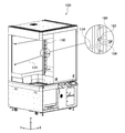
- FIG. 1 is a perspective view of the crane game device 100.
- the crane game device 100 is generally installed in an amusement park, a game center, or other amusement facility.
- the left-right direction of the crane game device 100 when viewed from the player will be the X direction
- the front-back direction will be the Y direction
- the up-down direction will be the Z direction.
- the crane game device 100 includes a rectangular parallelepiped base 102 and a box-shaped prize accommodating portion 104 provided on the base 102.
- a play space S is formed inside the prize accommodating portion 104, and a prize mounting stand 106 (game field) is provided.
- a prize mounting stand 106 (game field) is provided on the prize stand 106.
- On the prize stand 106 in addition to prizes such as stuffed animals and miscellaneous goods, color balls for decorating the prize stand 106 are arranged (described later).
- a crane 108 is provided above the prize mounting table 106. The crane 108 can move back and forth, left and right, and up and down in the play space S to grip / release the prize.
- the front surface and left and right sides of the prize storage unit 104 are covered with transparent glass. The visibility of the prize from the outside is taken into consideration.
- a camera that captures the prize mounting table 106 from above may be installed on the ceiling surface of the prize storage unit 104.
- a glass door 110 is provided on the front surface of the prize storage unit 104, and an operator (clerk) can open the door 110 to arrange the prize in the prize storage unit 104.
- the prize mounting table 106 is divided into a mounting area 112 (first area) and a drop port 114 (second area). If the prize is placed in the mounting area 112 and the player can carry the prize from the mounting area 112 to the drop port 114, the prize can be obtained.
- a shielding plate 128 is installed between the mounting area 112 and the drop port 114. The shielding plate 128 prevents the prize or the color ball in the mounting area 112 from rolling down to the drop port 114.
- a prize outlet 116 for taking out the prize that has fallen from the drop port 114 is formed on the front surface of the base 102.
- An operation unit 118 and a setting display unit 120 are provided on the front side of the base 102.
- the player inserts a coin into the coin slot or touches an IC card charged with electronic money to the IC card reader.
- the surface on which the operation unit 118 and the like are installed in other words, the surface on the side where the player is located is referred to as "front”, and is on the back side (Y-axis positive direction side) when viewed from the player.
- the surface is called the "back”.
- the operation unit 118 includes an operation rod 122 for the player to move the crane 108 back and forth and left and right to determine the descent point, and a grip button 124 for lowering the crane 108 to grip the prize.
- a touch panel is installed on the setting display unit 120.
- the setting display unit 120 functions as a "setting input unit” for the operator (clerk) to input game setting information, and is an “information display unit” for displaying information related to the game such as the operation method of the operation unit 118 and the game result. Also works as.
- the crane game device 100 also includes a speaker (not shown), an external connection terminal, and the like.
- the crane 108 has three arms 126 capable of gripping and releasing the prize.
- the crane 108 includes a motor that opens and closes the arm 126.
- the crane 108 grips and releases the prize by opening and closing the arm 126.
- the crane 108 can be moved along a guide rail (not shown) installed above the prize accommodating portion 104, and is driven by the crane driving unit 130 (described later).
- the crane driving unit 130 includes a moving mechanism that drives the crane 108 in the lateral direction (X direction) and the vertical direction (Y direction), and an elevating mechanism that drives the crane 108 in the vertical direction (Z direction).
- the moving mechanism includes an X-direction motor and a Y-direction motor.
- the elevating mechanism includes a Z-direction motor.
- the crane drive unit 130 can move the crane 108 to an arbitrary position in the play space S.
- the crane 108 in this embodiment is a so-called "triple catcher type" having three arms 126.
- the player can freely move the crane 108 back and forth and left and right by the operating rod 122 within the time limit.
- the player presses the grip button 124 after moving the crane 108 above the prize.
- the grip button 124 is pressed, the crane 108 is lowered.
- the arm 126 is automatically moved in the closing direction (hereinafter, referred to as "grasping” or “grasping operation”). At this time, the crane 108 can grab a relatively large prize at the drop zone by the arm 126. If the grip button 124 is pressed again while the crane 108 is descending, the arm 126 can be gripped at the time of pressing.
- the crane 108 rises while maintaining the gripping operation, and then automatically moves toward the drop port 114.
- the crane 108 moves the arm 126 in the release direction on the drop port 114 (hereinafter, referred to as "release” or “release operation”). If the prize is firmly grasped, the prize is carried by the crane 108 to the drop port 114 and dropped from above the drop port 114 (success of the crane game). On the other hand, when the arm 126 is not able to firmly grip the prize, the prize falls from the crane 108 before the crane 108 reaches directly above the drop port 114 (crane game failure).
- the operator can also rotate the crane 108 horizontally (rotate around the Z axis). As shown in FIG. 1, the home position is a state in which one of the three arms 126 is on the player side, but the operator can adjust the horizontal rotation angle of the crane 108 in consideration of the arrangement of prizes.
- a design cover 132 is installed on the front surface of the crane 108.
- a logo (advertising information) indicating a product name is described on the design cover 132 in this embodiment.
- the direction of the design cover 132 can also be adjusted in response to the horizontal rotation of the crane 108, but details will be described later in relation to FIG. 14 and the like.
- a plurality of optical sensors are installed inside the drop port 114. This optical sensor detects the fall of the prize into the drop port 114 (hereinafter, also simply referred to as "premium acquisition"). Further, these optical sensors are configured so as to be able to distinguish which of the color ball and the prize has fallen, and the details will be described later in relation to FIG. 8 and the like.
- One or more display bars 134 are installed on the back surface of the prize storage unit 104.
- the display bar 134 is a metal rod material extending in the X direction, and a prize for display can be sandwiched therein.
- the operator opens the door 110, enters the drop port 114, and installs the display bar 134 on the back surface.
- the number and height of the display bars 134 are arbitrary. The method of installing the display bar 134 will be described later in relation to FIGS. 11 and 11.
- a storage box for storing equipment such as colored balls is provided at the back of the drop port 114. This storage box will be described in detail later in relation to FIG.
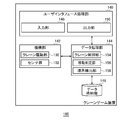
- FIG. 2 is a functional block diagram of the crane game device 100.
- Each component of the crane game device 100 includes a CPU (Central Processing Unit), a computing unit such as various coprocessors, a storage device such as a memory and a storage device, hardware including a wired or wireless communication line connecting them, and a storage device. It is stored in and realized by software that supplies processing instructions to the arithmetic unit.
- a computer program may be composed of a device driver, an operating system, various application programs located on the upper layers thereof, and a library that provides common functions to these programs.
- Each block described below shows a block for each function, not a configuration for each hardware.
- the crane game device 100 includes a user interface processing unit 140, a mechanism unit 142, a data processing unit 144, and a data storage unit 146.
- the user interface processing unit 140 accepts operations from the player via various input devices, and is in charge of processing related to the user interface such as image display and audio output.
- the mechanism unit 142 drives various mechanisms such as the crane 108.
- the data storage unit 146 stores various data.
- the data processing unit 144 executes various processes based on the input from the user interface processing unit 140 and the data stored in the data storage unit 146.
- the data processing unit 144 also functions as an interface for the mechanism unit 142, the user interface processing unit 140, and the data storage unit 146.
- the user interface processing unit 140 includes an input unit 148 and an output unit 150 that outputs various information such as images and sounds.
- the input unit 148 receives the setting input from the operator via the setting display unit 120. Further, the input unit 148 receives an operation input from the player via the operation unit 118.
- the crane game device 100 has a setting mode and a play mode. In the setting mode, the operator makes various settings described later. The delivery of prizes or the attachment of the display bar 134 is also performed during the setting mode. In the play mode, the player operates the operation unit 118 to play the crane game.
- the mechanism unit 142 includes the crane drive unit 130 and the sensor group 152. As described above, the crane driving unit 130 moves the crane 108 and grips and releases the arm 126.
- the sensor group 152 corresponds to an optical sensor (described later) at the drop port 114, an optical sensor that detects the position of the plate (described later) in the mounting area 112, and the like.
- the data processing unit 144 includes a crane control unit 154, a movement determination unit 156, and a boundary detection unit 158.
- the crane control unit 154 instructs the crane 108 to move, grip, and release according to the operation instruction by the operation unit 118.
- the movement determination unit 156 determines whether the prize has fallen into the drop port 114, in other words, the success or failure of the crane game.
- the boundary detection unit 158 detects the boundary position between the drop port 114 and the placement area 112. The details of the boundary position detection method will be described later.
- the data storage unit 146 stores information such as a crane game game program, a crane game setting, and a game play result (payout rate).
- a crane game game program such as a crane game program, a crane game setting, and a game play result (payout rate).
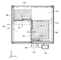
- FIG. 3 is a top view of the prize mounting table 106.
- the prize mounting table 106 includes the mounting area 112 and the drop port 114.
- the mounting area 112 further includes a first mounting area 112a located on the Y-axis positive direction side (back side) of the drop port 114, a second mounting area 112b located on the X-axis positive direction side (right side), and a drop. It is composed of a third mounting area 112c located diagonally behind the mouth 114.
- the upper part of the first mounting area 112a is covered with the Y plate 160 (first plate).
- the upper part of the second mounting area 112b is covered with the X plate 162 (second plate).
- the upper surface of the Y plate 160 in the first mounting region 112a, the upper surface of the X plate 162 in the second mounting region 112b, and the upper surface of the third mounting region 112c are formed so as to be flush with each other.
- the Y plate 160 (covering the first mounting area 112a), the X plate 162 (covering the second mounting area 112b), and the third mounting area 112c (exposed) have steps on their respective upper surfaces. It is configured not to.
- the X plate 162 can move horizontally in the negative direction of the X axis. By horizontally moving the X plate 162, the operator can reduce the size (width) of the drop port 114.
- a shielding plate 128 is fixed to the end of the X plate 162. As the X plate 162 moves, the shielding plate 128 also moves in the direction of narrowing the drop port 114.
- the second mounting area 112b is provided with a position detection sensor 164 (optical sensor) for detecting the amount of movement of the X plate 162, in other words, the position of the X plate 162. The details of the detection method will be described later in relation to FIGS. 4 and later.
- the Y plate 160 can move horizontally in the negative direction of the Y axis. By horizontally moving the Y plate 160, the operator can reduce the size (vertical width) of the drop port 114. Since the shielding plate 128 is also fixed to the end of the Y plate 160, the shielding plate 128 also moves in the direction of narrowing the drop port 114 as the Y plate 160 moves. Although not shown, the amount of movement of the Y plate 160 can also be detected by the same method as that of the X plate 162.
- the Y plate 160 and the X plate 162 cannot be moved at the same time.
- the Y plate 160 is moved in the negative direction on the Y axis to narrow the drop port 114 in the Y direction
- the X plate 162 cannot be moved.
- the Y plate 160 cannot be moved. This is because the upper surfaces of the Y plate 160 and the X plate 162 are made to have the same height, instead of intersecting the Y plate 160 and the X plate 162 with a step.
- the prize or the arm 126 may be caught in the step and the play may be hindered.
- the Y plate 160, the X plate 162, and the third mounting region 112c are formed so as to be flush with each other.
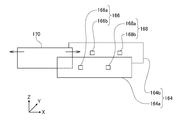
- FIG. 4 is a configuration diagram of the position detection sensor 164.
- a detection plate 170 projecting in the negative direction of the Z axis is fixed to the lower surface of the X plate 162.
- the position detection sensor 164 includes a transmission plate 164a and a reception plate 164b.
- the transmitting plate 164a and the receiving plate 164b project in the positive direction of the Z axis on the upper surface of the second mounting region 112b.
- the detection plate 170 moves between the transmission plate 164a and the reception plate 164b as the X plate 162 moves in the X direction.
- the position detection sensor 164 includes a first optical sensor 166 and a second optical sensor 168.
- the first optical sensor 166 has a first transmitter 166a that emits optical signals such as infrared rays and laser light on the transmitter plate 164a, and a first receiver 166b that receives optical signals from the first transmitter 166a on the receiver plate 164b.
- the second optical sensor 168 includes a second oscillator 168a that emits an optical signal on the transmitting plate 164a and a second receiver 168b that receives an optical signal from the second oscillator 168a on the receiving plate 164b.
- the amount of movement m of the X plate 162 in the negative direction of the X axis is set in three stages.
- the X coordinate of the boundary position of the tip of the X plate 162 (hereinafter referred to as "X boundary coordinate") is registered.
- the boundary detection unit 158 detects the X boundary coordinates by measuring the movement amount m with the position detection sensor 164.
- both the first optical sensor 166 and the second optical sensor 168 are shielded by the detection plate 170, so that both the first receiver 166b and the second receiver 168b are both. Does not detect optical signals.
- the boundary detection unit 158 determines that the movement amount m of the X plate 162 is zero when the light detection signal is not received from both the first receiver 166b and the second receiver 168b.
- only the first optical sensor 166 is shielded by the detection plate 170, so that the first receiver 166b does not detect the optical signal and the second receiver 168b does not detect the optical signal. Is detected.
- the boundary detection unit 158 receives the light detection signal only from the second receiver 168b, the boundary detection unit 158 determines that the movement amount m of the X plate 162 is the intermediate value X1.
- neither the first optical sensor 166 nor the second optical sensor 168 is shielded by the detection plate 170, so that both the first receiver 166b and the second receiver 168b are light.
- Detect the signal the boundary detection unit 158 receives the light detection signal from both the first receiver 166b and the second receiver 168b
- the boundary detection unit 158 determines that the movement amount m of the X plate 162 is the maximum value X2.
- the amount n of movement of the Y plate 160 in the negative direction of the Y axis can be detected in the same manner.
- Y boundary coordinate the Y coordinate of the boundary position of the tip of the Y plate 160 (hereinafter referred to as "Y boundary coordinate" is registered.
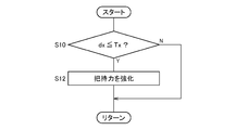
- FIG. 6 is a flowchart showing the gripping force adjusting process of the arm 126.
- the crane control unit 154 increases the gripping force of the arm 126 when the crane 108 approaches the drop port 114.
- the crane 108 grabs the prize, the player expects the prize to be carried to the drop port 114 without falling in the middle. Therefore, in the present embodiment, when the distance dx between the X coordinate of the crane 108 (hereinafter referred to as “X crane coordinate”) and the X boundary coordinate becomes equal to or less than a predetermined threshold value Tx (Y in S10), the crane control unit 154 increases the gripping force of the arm 126 (S12). When the distance dx is larger than the threshold value Tx (N in S10), the gripping force is not changed.
- the boundary detection unit 158 specifies the movement amount m of the X plate 162 in advance by the position detection sensor 164.
- the boundary detection unit 158 specifies the X boundary coordinates depending on which of the three stages of movement amount m.
- the crane control unit 154 calculates the distance dx based on the X boundary coordinates and the X crane coordinates.
- the movement determination unit 156 may detect the X crane coordinates by a rotary encoder (not shown) mounted on the crane 108. Not limited to this, the movement determination unit 156 may calculate the X crane coordinates by a known technique such as laser measurement or image recognition by a camera.
- the Y coordinate may be determined in the same manner.
- the crane control unit 154 increases the gripping force of the arm 126 even when the distance dy between the Y boundary coordinates and the Y coordinates of the crane 108 (hereinafter referred to as "Y crane coordinates") is equal to or less than a predetermined threshold value Ty. May be good.
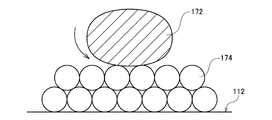
- FIG. 7 is a schematic view showing a placement state of the prize 172 in the placement area 112.
- a plurality of color balls 174 are spread over the mounting area 112.
- Various prizes 172 such as stuffed animals are placed on the layer of the color balls 174.
- the color ball 174 is an elastic vinyl ball.
- One of the purposes of laying out the color balls 174 is to enhance the decorativeness of the play space S.
- the arm 126 directly touches the mounting area 112, the arm 126 or the mounting area 112 may be scratched. Therefore, the mounting area 112 and the arm 126 are formed by forming a layer of the color balls 174. Prevent contact.
- the layer of the color ball 174 creates a gap under the prize 172, it becomes easy to insert the arm 126 into the lower part of the prize 172. Therefore, by forming the layer of the color ball 174, the arm 126 can easily grasp the prize 172 firmly.
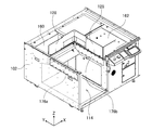
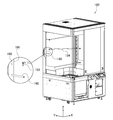
- FIG. 8 is a perspective view of the base 102.
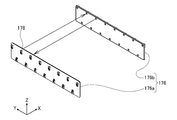
- FIG. 9 is a perspective view of the price sensor 176.
- a price sensor 176 is arranged on the inner wall surface of the drop port 114.
- the price sensor 176 includes a first detection plate 176a and a second detection plate 176b that face each other.
- a total of 30 optical sensors 178 are arranged on the first detection plate 176a and the second detection plate 176b, 15 each.
- optical sensors 178 are arranged on the upper stage of the first detection plate 176a and seven optical sensors 178 are arranged on the lower stage, and the same applies to the second detection plate 176b. Fifteen optical sensors 178 arranged on each of the first detection plate 176a and the second detection plate 176b are arranged so as to face each other, forming a total of 15 pairs. Similar to the position detection sensor 164, one optical sensor 178 functions as a photodetector and the other optical sensor 178 facing it functions as an optical receiver. An optical signal is constantly transmitted from one of the two paired optical sensors 178 to the other.
- the movement determination unit 156 receives an optical detection signal from each pair of optical sensors 178.
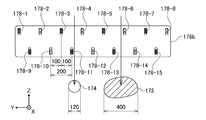
- FIG. 10 is a schematic diagram for explaining a method of detecting the prize 172 and the color ball 174.
- the second detection version 176b eight optical sensors 178 from the optical sensor 178-1 to the optical sensor 178-8 are arranged in the upper stage, and seven optical sensors 178 from the optical sensor 178-9 to the optical sensor 178-15 are arranged. Is placed in the lower row. The upper and lower optical sensors are offset by the Y coordinate of each 178 installation position.
- the distance between the upper optical sensor 178 (for example, the optical sensor 178-3) and the lower optical sensor 178 (for example, the optical sensor 178-11) next to it in the Y direction is 100 mm. Further, it is assumed that the distance between the lower optical sensor 178 (for example, the optical sensor 178-10) and the lower optical sensor 178 (for example, the optical sensor 178-11) adjacent thereto in the Y direction is 200 mm. It is assumed that the diameter of the color ball 174 in this embodiment is 120 mm. Further, it is assumed that the width of the prize 172 is at least 400 mm or more.
- the optical signal of the lower optical sensor 178-11 is temporarily cut off (hereinafter referred to as "passing reaction").
- passing reaction the optical signal of the lower optical sensor 178-11
- the diameter of the color ball 174 is 120 mm, and the distance from the optical sensor 178-11 to the optical sensor 178-12 next to it is 200 mm. Therefore, when the color ball 174 is dropped, the passing reaction is not detected from the optical sensors other than the optical sensor 178-11 in the lower stage. The same applies to the upper row. Therefore, in the movement determination unit 156, when the passing reaction is detected by any of the optical sensors 178 and the number of passing reactions in the upper stage is 1 or less and the number of passing reactions in the lower stage is 1 or less, the color ball 174 has fallen. Is determined.
- a passing reaction is detected by one or more optical sensors 178.
- the passing reaction is detected by the upper optical sensor 178-6 and the lower optical sensor 178-13 and the optical sensor 178-14. Since the prize 172 is larger than the color ball 174, a passing reaction is detected by two or more adjacent optical sensors 178 in the same stage. Therefore, the movement determination unit 156 determines that the prize 172 has fallen when the passing reaction is generated by the upper and lower optical sensors 178 and the number of passing reactions in either the upper or lower stage is 2 or more.
- FIG. 11 is a first exploded perspective view of the crane game device 100 showing a state when the display bar 134 is installed.
- the display bar 134 is a metal rod-shaped member whose one end is bent at a right angle.
- the operator first installs the display bar 134 on the first support column 180 at the back of the crane game device 100 (on the positive direction side of the X axis).
- a plurality of lateral grooves 182 are formed in the first support column 180.
- the operator inserts the insertion portion 184 at the tip of the display bar 134 into the lateral groove 182 of the first support column 180 from the horizontal direction. Details of the fitting structure of the insertion portion 184 and the lateral groove 182 will be described later in relation to FIG.
- FIG. 12 is a second exploded perspective view of the crane game device 100 showing a state when the display bar 134 is installed. Also in FIG. 12, some members such as the door 110 are deleted and drawn. A plurality of insertion holes 188 are formed in advance in the second support column 186 on the front side (X-axis negative direction side) of the back surface of the crane game device 100. The position of the insertion hole 188 is the same height as the position of the lateral groove 182 of the first support column 180.
- the operator inserts the support rod 190 into an arbitrary insertion hole 188.
- the operator inserts one end (back side) of the display bar 134 into the lateral groove 182 of the first support column 180, and then hooks the hook 192 at the other end (front side) of the display bar 134 on the support rod 190 to lock the display bar 134.
- the operator inserts one end of the display bar 134 into the first support column 180, and then hooks the other end of the display bar 134 on the support rod 190 to attach the display bar 134 to the second support column 186 and the first support column 180. Fix it.
- the work of installing the display bar 134 on the first column 180 has been a heavy burden.
- the operator opens the door in front of the prize outlet 116 and the glass door 110 of the prize storage unit 104 to enter the prize drop space (the space where the drop port 114 is formed).
- the prize drop space is located on the left side (X-axis negative direction) of the housing, so the right back of the housing (X-axis positive direction and) Many operators cannot reach the first column 180 located in the positive direction of the Y-axis).
- the hook 192 is hooked on the support rod 190 and locked on the front side, so that the display bar 134 can be easily installed.
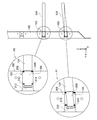
- FIG. 13 is an enlarged view of the fitting portion between the display bar 134 and the first support column 180.
- a plurality of lateral grooves 182 are formed in the first support column 180.
- the operator inserts a relatively small-diameter insertion portion 184 at the tip of the display bar 134 into the lateral groove 182 from the horizontal direction.
- a plate-shaped first support member 208 is formed on the front side (Y-axis negative direction side), and a plate-shaped second support member 210 is also formed on the back side (Y-axis positive direction side). Will be done.
- the first support member 208 is formed so as to be higher (relatively protruding) in the Z-axis direction than the second support member 210. Further, on the upper side of the lateral groove 182, the second support member 210 is formed so as to be lower (relatively protruding) than the first support member 208 in the Z-axis direction.
- the operator inserts the display bar 134 into the lateral groove 182 with the display bar 134 tilted slightly upward. Can be done.
- the back side of the insertion portion 184 is regulated by the relatively protruding second support member 210, and the front side is regulated by the relatively protruding first support member 208. Will be done.
- the regulating member 212 having a relatively large diameter is provided on the back side of the insertion portion 184, even if the display bar 134 is pulled in the front direction (Y-axis negative direction), the regulating member 210 is provided by the second support member 210. 212 is regulated. Due to such a structure, the display bar 134 is more difficult to come off.
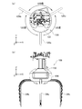
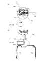
- FIG. 14A is a top view of the crane 108 at the time of initial setting.
- FIG. 14B is a front view of the crane 108 at the time of initial setting.
- the crane 108 has three arms 126 (first arm 126a, second arm 126b and third arm 126c).
- the first arm 126a, the second arm 126b, and the third arm 126c are each deviated by 120 degrees.
- the first arm 126a is usually provided at a position facing the player (see also FIG. 1).
- a design cover 132 is installed on the first arm 126a.
- a logo plate 194 is fixed to the design cover 132.
- the logo plate 194 functions as an advertisement or decoration for attracting the player to the crane game device 100.
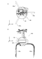
- FIG. 15A is a top view of the crane 108 when rotated by 30 degrees.
- FIG. 15B is a front view of the crane 108 when rotated by 30 degrees.
- the layout of the plurality of prizes 172 also changes. For example, if one prize 172 is near the drop port 114, it is considered that the player operates the crane 108 with the prize 172 as a target (acquisition target).
- the arm 126 may hit the shield plate 128 near the boundary of the drop port 114, making it difficult to grasp the prize 172. Therefore, usually, the operator may adjust the horizontal rotation angle of the crane 108 so that the arm 126 does not hit the shielding plate 128 while observing the arrangement state of the prize 172. Further, depending on the orientation of the prize 172, it may be easier to obtain the prize 172 by changing the position of the arm 126. The operator may rotate the crane 108 horizontally to make it easier to obtain the prize 172 in order to motivate the customer to play.
- the crane 108 is rotated 30 degrees clockwise when viewed from above.
- the design cover 132 and the logo plate 194 also face to the left when viewed from the player.
- the horizontal rotation angles of the cranes 108 often do not match.
- a large number of logo plates 194 are oriented in different directions, which may spoil the aesthetic appearance of the amusement facility.
- the logo plate 194 which should originally function as an advertisement when starting the crane game, is not facing the front (player side), some players may feel uncomfortable.
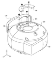
- FIG. 16A is a top view of the crane 108 when the design cover 132 is adjusted.
- FIG. 16B is a front view of the crane 108 when the design cover 132 is adjusted.
- the design cover 132 is configured to be horizontally rotatable independently of the crane 108 by the structure described later. The operator can adjust the logo plate 194 to face the front (player side) by rotating the crane 108 body clockwise and then rotating only the design cover 132 counterclockwise.
- FIG. 17 is an exploded perspective view of the crane 108 around the design cover 132.
- FIG. 18 is a side sectional view of the crane 108 around the design cover 132.
- a guide groove 204 is formed in the cover member 200 which is the outer wall of the crane 108, and the design cover holder 196 is sandwiched between the guide groove 204 and the lock plate 198.
- the lock plate 198 is fixed to the cover member 200 by screws.
- the design cover holder 196 can rotate horizontally along the guide groove 204 while being guided by the lock plate 198 in the horizontal plane (XY plane).
- the design cover 132 (logo plate 194) is fixed to the rotatable design cover holder 196 with screws.
- the operator holds the crane 108 with one hand and grabs and rotates the design cover 132 with the other hand to rotate the design cover 132 as shown in FIGS. 16A and 16B.
- the orientation can be adjusted manually.
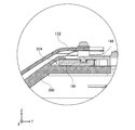
- FIG. 19 is a side sectional view of the storage box 206.
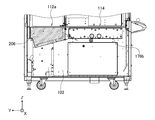
- FIG. 19 shows a cross section when the crane game device 100 is cut along the line AA of FIG. 1 and the line-of-sight direction is the positive direction of the X-axis.
- the storage box 206 is formed in the lower part of the first mounting area 112a.
- the storage box 206 forms a space for storing equipment such as a support rod 190 (see FIG. 12), a color ball 174, and various screws and tools.
- the lower surface of the storage box 206 is inclined.
- the tilt angle is 10 to 30 degrees, more preferably 12 to 20 degrees.
- the operator opens the door 110 of the prize storage unit 104 and the front door of the prize outlet 116, enters the fall port 114 (premium fall space), and uses the storage box 206. Since the lower surface of the storage box 206 is tilted, the operator can easily see the storage box 206 to the back without crouching excessively. In other words, by inclining the lower surface of the storage box 206 so as to approach the line-of-sight direction (looking down direction) of the operator during work, the operator can relatively easily check the depth of the storage box 206. Further, the storage size of the storage box 206 can be increased by providing the inclination angle.
- the crane game device 100 has been described above based on the embodiment.
- the gripping force of the arm 126 is strengthened. Therefore, when the crane 108 approaches the drop port 114, the possibility that the crane 108 will drop the prize 172 is reduced.
- the gripping force of the arm 126 becomes stronger, so that the player can further increase the expectation for the prize acquisition.
- the prize 172 is brought close to the drop opening 114 by playing a plurality of times, the possibility of acquiring the prize is increased, so that the player's motivation to continue the game is easily increased.
- the operator can freely change the shape of the drop port 114 by horizontally moving the Y plate 160 or the X plate 162.
- the "shape" here may be any one or more of the opening size (area) of the drop port 114, the X boundary coordinates, and the Y boundary coordinates.
- the X boundary coordinates and the Y boundary coordinates when the X plate 162 or the like is horizontally moved are automatically detected by the position detection sensor 164 and the boundary detection unit 158.
- the crane control unit 154 can appropriately change the strengthening timing of the gripping force of the arm 126 based on the detection result. In this way, the operator can automatically and appropriately adjust the gripping force of the arm 126 by simply moving the X plate 162 or the like without making other settings.
- the mounting area 112 is covered with colorful colored balls 174, and the prize 172 is placed on the layer of the colored balls 174. Therefore, it is conceivable that the color ball 174, instead of the prize 172, falls into the drop port 114.
- the price sensor 176 formed on the inner wall of the drop port 114 includes a plurality of optical sensors 178. Depending on the number of passing reactions of the optical sensor 178, the movement determination unit 156 can determine in a simple configuration whether the prize 172 or the color ball 174 has fallen.
- the crane game device 100 has a structure in which the display bar 134 can be easily fitted into the first support column 180 on the back side, which is particularly difficult to attach when the display bar 134 is attached.
- the operator can stabilize the display bar 134 in the first support column 180 by inserting the display bar 134 into the lateral groove 182 formed in the first support column 180 from the side. After inserting the display bar 134 into the first support column 180, the operator can easily fix the display bar 134 by hooking the hook 192 of the display bar 134 on the support rod 190. Therefore, the display bar 134 can be easily installed even when the first support column 180 cannot be reached.
- the crane 108 in this embodiment can rotate horizontally depending on the situation of the crane game. Since the design cover 132 can be rotated horizontally relative to the crane 108, the design cover 132 (logo plate 194) can be adjusted to face the player regardless of the orientation of the crane 108. In particular, when arranging a plurality of crane game devices 100, if the logo plates 194 of all the crane game devices 100 are oriented in the same direction, not only the visibility of the logo plates 194 is improved, but also a sense of unity in the amusement facility is achieved. It is also effective for making.
- the storage box 206 is further formed in a part of the base 102.
- the workability of the operator can be improved. Further, this can effectively expand the storage space of the storage box 206.
- the present invention is not limited to the above-described embodiment or modification, and the components can be modified and embodied within a range that does not deviate from the gist.
- Various inventions may be formed by appropriately combining a plurality of components disclosed in the above embodiments and modifications.
- some components may be deleted from all the components shown in the above embodiments and modifications.
- the distance dx is calculated based on the X boundary coordinates and the X crane coordinates, and when the distance dx is equal to or less than the threshold value Tx, the crane control unit 154 strengthens the gripping force of the arm 126.
- the crane control unit 154 may set the gripping force of the arm 126 to "normal” regardless of the X crane coordinates.
- the crane control unit 154 sets the gripping force of the arm 126 to "strong (for example, 130% of the normal time)" regardless of the X crane coordinates. It may be set.
- the gripping force is weak, and when the opening size of the fall port 114 is small, the gripping force is set large. Can be stabilized. The same applies when adjusting the opening size of the drop port 114 with the Y plate 160.
- the difficulty level may be greatly changed in conjunction with the opening size by weakening the gripping force when the opening size of the falling port 114 is small and increasing the gripping force when the opening size of the falling port 114 is large.
- the gripping force may be adjusted according to the opening size of the drop port 114, not limited to the distance between the drop port 114 and the crane 108.
- the X boundary coordinates and the Y boundary coordinates have been described as being detected by the boundary detection unit 158 based on the movement amount of the X plate 162 and the Y plate 160.
- the operator may horizontally move the X plate 162 or the like and then input the X boundary coordinates or the like as setting information via the setting display unit 120.
- the boundary detection unit 158 may specify the X boundary coordinates of the drop port 114 based on this setting information.
- the gripping force when the crane 108 approaches the X boundary coordinates, the gripping force is strengthened to raise the expectation of the player to acquire the prize.
- the gripping force may be weakened when the crane 108 approaches the X boundary coordinates.
- the gripping force of the arm 126 is set to "strong" at the initial stage, and when the distance dx between the X boundary coordinates and the X crane coordinates becomes equal to or less than the threshold value Tx, the crane control unit 154 sets the gripping force of the arm 126. It may be set to "medium” or "weak". According to such a control method, since the arm 126 has a strong initial gripping force, it is less likely that the prize 172 will fail to be lifted.
- the difficulty level of the crane game is excessively lowered, and the expectation of obtaining a prize is excessively increased. Can be prevented.
- the disappointment caused by the arm 126 not being able to grab the prize 172 is less likely to occur at an early stage, and the crane 108 is tense when carrying the prize 172. It makes it easier for more players to experience the feeling. The same applies to the distance dy between the Y boundary coordinates and the Y crane coordinates.
- the crane control unit 154 when the distance dx is equal to or less than a predetermined threshold value Tx, the crane control unit 154 weakens the gripping force of the arm 126.
- the crane control unit 154 may gradually (continuously) weaken the gripping force of the arm 126 as the distance dx decreases.
- the gripping force of the arm 126 may be gradually increased as the distance dx becomes smaller. The same applies to the distance dy.
- the gripping force of the arm 126 may be discontinuously changed according to the distance dx.
- the gripping force of the arm 126 when the distance dx is larger than the threshold value T1 (long distance), the gripping force of the arm 126 is set to "normal", and when the distance dx is equal to or less than the threshold value T1 and larger than the threshold value T2 ( ⁇ T1) (medium distance).
- the gripping force of the arm 126 may be set to "weak", and when the distance dx is equal to or less than the threshold value T2 (short distance), the gripping force of the arm 126 may be set to "strong".
- the crane control unit 154 may control the gripping force of the arm 126 according to the shape of the drop port 114, the distance dx, the distance dy, and the operating time of the crane 108.
- the timer may be started at the start of the crane game, and as time elapses, the crane control unit 154 may weaken or strengthen the gripping force of the arm 126.
- the game components other than the gripping force of the arm 126 may be controlled based on the shape of the drop port 114, the distance between the drop port 114 and the crane 108, and the like. For example, when the distance dx becomes equal to or less than a predetermined threshold value, the output unit 150 may change the BGM (background music) or change the volume of the BGM. Further, when the monitor is installed in the crane game device 100, the output unit 150 may change the image to be displayed on the monitor according to the distance dx.
- BGM background music
- the output unit 150 may change the image to be displayed on the monitor according to the distance dx.
- the crane control unit 154 may change the moving speed of the crane 108 when the distance dx becomes equal to or less than a predetermined threshold value. For example, the crane control unit 154 reduces the moving speed of the crane 108 before the crane 108 grabs the prize 172 to make it easier to grab the prize 172, and increases the moving speed of the crane 108 after the crane 108 grabs the prize 172. The tension of the game may be increased by making the prize 172 easy to drop.
- the design cover 132 may mount a monitor instead of the logo plate 194.
- the output unit 150 may change the image to be displayed on the monitor of the design cover 132 according to the distance dx.
- the prize 172 and the color ball 174 are discriminated by the price sensor 176.
- a plurality of types of prizes 172 having different sizes may be placed in the mounting area 112.
- the movement determination unit 156 may determine which of the plurality of types of prizes 172 the prize 172 has fallen into the drop port 114.
- the price sensor 176 has been described as having a plurality of optical sensors 178 arranged in two rows, an upper row and a lower row, the plurality of optical sensors 178 may be arranged in one row or three or more rows. .. The interval between the optical sensors 178 may be adjusted so that the number of passing reactions of the optical sensor 178 differs according to the size of the falling object.
- the crane game device 100 can also be applied to a so-called net catcher.
- the net catcher is a crane game in which a player operates a crane 108 of a crane game device 100 at a remote location by transmitting operation information while confirming the state of prize acquisition on a PC in real time by a camera image. The prize acquired by the player is mailed to the player.
- the prize placing table 106 is provided with a first area for placing the prize 172 and a second area for moving the prize 172.
- the second region may be formed as a drop port 114 or may be a simple panel.
- Crane game device 102 base, 104 prize storage, 106 prize mounting table, 108 crane, 110 door, 112 mounting area, 112a 1st mounting area, 112b 2nd mounting area, 112c 3rd mounting area , 114 drop port, 116 prize outlet, 118 operation unit, 120 setting display unit, 122 operation rod, 124 grip button, 126 arm, 126a 1st arm, 126b 2nd arm, 126c 3rd arm, 128 shielding plate, 130 Crane drive unit, 132 design cover, 134 display bar, 140 user interface processing unit, 142 mechanism unit, 144 data processing unit, 146 data storage unit, 148 input unit, 150 output unit, 152 sensor group, 154 crane control unit, 156 Movement judgment unit, 158 boundary detection unit, 160 Y plate, 162 X plate, 164 position detection sensor, 164a transmitter plate, 164b receiver plate, 166 first optical sensor, 166a first transmitter, 166b first receiver, 168th 2 optical sensor, 168a second oscillator
Landscapes
- Engineering & Computer Science (AREA)
- Multimedia (AREA)
- Physics & Mathematics (AREA)
- General Physics & Mathematics (AREA)
- Pinball Game Machines (AREA)
- Toys (AREA)
Priority Applications (4)
| Application Number | Priority Date | Filing Date | Title |
|---|---|---|---|
| CN202180022480.XA CN115315295A (zh) | 2020-03-19 | 2021-03-18 | 物品取得游戏装置 |
| CN202411548901.4A CN119455369A (zh) | 2020-03-19 | 2021-03-18 | 物品取得游戏装置 |
| CN202411551110.7A CN119455370A (zh) | 2020-03-19 | 2021-03-18 | 物品取得游戏装置 |
| CN202411548884.4A CN119455368A (zh) | 2020-03-19 | 2021-03-18 | 物品取得游戏装置 |
Applications Claiming Priority (2)
| Application Number | Priority Date | Filing Date | Title |
|---|---|---|---|
| JP2020049275A JP7396145B2 (ja) | 2020-03-19 | 2020-03-19 | 物品取得ゲーム装置 |
| JP2020-049275 | 2020-03-19 |
Publications (1)
| Publication Number | Publication Date |
|---|---|
| WO2021187614A1 true WO2021187614A1 (ja) | 2021-09-23 |
Family
ID=77768172
Family Applications (1)
| Application Number | Title | Priority Date | Filing Date |
|---|---|---|---|
| PCT/JP2021/011272 Ceased WO2021187614A1 (ja) | 2020-03-19 | 2021-03-18 | 物品取得ゲーム装置 |
Country Status (3)
| Country | Link |
|---|---|
| JP (3) | JP7396145B2 (enExample) |
| CN (4) | CN115315295A (enExample) |
| WO (1) | WO2021187614A1 (enExample) |
Families Citing this family (5)
| Publication number | Priority date | Publication date | Assignee | Title |
|---|---|---|---|---|
| JP7331183B1 (ja) * | 2022-03-18 | 2023-08-22 | スタンバイ株式会社 | クレーンゲーム装置 |
| JP7454151B2 (ja) * | 2022-07-26 | 2024-03-22 | 株式会社サファリゲームズ | 景品把持ゲーム機及び把持力設定方法 |
| JP2024068283A (ja) * | 2022-11-08 | 2024-05-20 | 株式会社セガ | 物品取得ゲーム装置 |
| JP7479021B1 (ja) | 2023-05-12 | 2024-05-08 | 株式会社サファリゲームズ | 景品獲得ゲーム機 |
| JP2025060284A (ja) * | 2023-09-29 | 2025-04-10 | 株式会社セガ | 景品取得ゲーム装置 |
Citations (5)
| Publication number | Priority date | Publication date | Assignee | Title |
|---|---|---|---|---|
| JP2002239209A (ja) * | 2001-02-16 | 2002-08-27 | Aruze Corp | クレーンゲーム機 |
| JP3183726U (ja) * | 2013-03-15 | 2013-05-30 | 株式会社バンダイナムコゲームス | 景品獲得ゲーム装置用の景品載置部 |
| JP2017093645A (ja) * | 2015-11-19 | 2017-06-01 | 株式会社タイトー | ゲーム装置 |
| JP2017184939A (ja) * | 2016-04-04 | 2017-10-12 | 株式会社セガゲームス | 景品取得ゲーム装置 |
| JP2019098076A (ja) * | 2017-12-07 | 2019-06-24 | 株式会社セガゲームス | 景品取得ゲーム装置 |
Family Cites Families (12)
| Publication number | Priority date | Publication date | Assignee | Title |
|---|---|---|---|---|
| JPH11226240A (ja) * | 1998-02-17 | 1999-08-24 | Sega Enterp Ltd | クレーンゲーム装置 |
| JP2004180137A (ja) * | 2002-11-28 | 2004-06-24 | Sony Corp | 撮像装置 |
| JP3095324U (ja) * | 2003-01-17 | 2003-07-31 | 株式会社日本アミューズメント | クレーンゲーム機における景品キャッチャーのカバー |
| JP3916075B2 (ja) * | 2003-09-10 | 2007-05-16 | 株式会社タイトー | クレーンゲーム機 |
| JP2005323788A (ja) * | 2004-05-14 | 2005-11-24 | Taito Corp | クレーンゲーム機の景品キャッチャー制御方法 |
| JP3838254B2 (ja) * | 2004-10-29 | 2006-10-25 | 株式会社セガ | 景品取得ゲーム装置 |
| JP5191277B2 (ja) * | 2008-05-21 | 2013-05-08 | 株式会社タイトー | Pop表示機能を有するクレーンゲーム機 |
| AU2010216749B2 (en) * | 2009-02-19 | 2015-07-16 | Bandai Namco Entertainment Inc. | Prize winning game device |
| JP5429532B2 (ja) * | 2009-06-10 | 2014-02-26 | 株式会社セガ | 景品取得装置 |
| JP2016140723A (ja) * | 2015-02-05 | 2016-08-08 | 株式会社エンハート | 景品取得ゲーム装置および景品取得ゲームプログラム |
| CN107198874A (zh) * | 2017-06-08 | 2017-09-26 | 车青山 | 一种可多区域抓取的娃娃机及其实现和抓取方法 |
| CN107773978B (zh) * | 2017-10-26 | 2020-12-18 | 广州市雷军游乐设备有限公司 | 控制抓取道具模型的方法、装置、终端设备及存储介质 |
-
2020
- 2020-03-19 JP JP2020049275A patent/JP7396145B2/ja active Active
-
2021
- 2021-03-18 CN CN202180022480.XA patent/CN115315295A/zh active Pending
- 2021-03-18 CN CN202411548884.4A patent/CN119455368A/zh active Pending
- 2021-03-18 CN CN202411548901.4A patent/CN119455369A/zh active Pending
- 2021-03-18 CN CN202411551110.7A patent/CN119455370A/zh active Pending
- 2021-03-18 WO PCT/JP2021/011272 patent/WO2021187614A1/ja not_active Ceased
-
2023
- 2023-11-29 JP JP2023201185A patent/JP7662012B2/ja active Active
-
2025
- 2025-03-25 JP JP2025049464A patent/JP2025085846A/ja active Pending
Patent Citations (5)
| Publication number | Priority date | Publication date | Assignee | Title |
|---|---|---|---|---|
| JP2002239209A (ja) * | 2001-02-16 | 2002-08-27 | Aruze Corp | クレーンゲーム機 |
| JP3183726U (ja) * | 2013-03-15 | 2013-05-30 | 株式会社バンダイナムコゲームス | 景品獲得ゲーム装置用の景品載置部 |
| JP2017093645A (ja) * | 2015-11-19 | 2017-06-01 | 株式会社タイトー | ゲーム装置 |
| JP2017184939A (ja) * | 2016-04-04 | 2017-10-12 | 株式会社セガゲームス | 景品取得ゲーム装置 |
| JP2019098076A (ja) * | 2017-12-07 | 2019-06-24 | 株式会社セガゲームス | 景品取得ゲーム装置 |
Also Published As
| Publication number | Publication date |
|---|---|
| JP2024009303A (ja) | 2024-01-19 |
| JP2021145937A (ja) | 2021-09-27 |
| JP2025085846A (ja) | 2025-06-05 |
| CN119455370A (zh) | 2025-02-18 |
| JP7662012B2 (ja) | 2025-04-15 |
| JP7396145B2 (ja) | 2023-12-12 |
| CN119455368A (zh) | 2025-02-18 |
| CN115315295A (zh) | 2022-11-08 |
| CN119455369A (zh) | 2025-02-18 |
Similar Documents
| Publication | Publication Date | Title |
|---|---|---|
| JP7662012B2 (ja) | 物品取得ゲーム装置 | |
| CN104274970B (zh) | 游戏机 | |
| JP5647960B2 (ja) | ゲームシステム | |
| US20100248833A1 (en) | Game apparatus and game program | |
| JP7260048B2 (ja) | 物品取得ゲーム装置 | |
| JP2004141265A (ja) | 遊技機 | |
| JP2005177116A (ja) | 弾球遊技機 | |
| JP7509264B2 (ja) | 物品取得ゲーム装置 | |
| JP2009078029A (ja) | 遊技機用表示ユニット及び遊技機 | |
| JP6685711B2 (ja) | 遊技機 | |
| JP6840027B2 (ja) | 景品獲得ゲーム機及び昇降装置 | |
| JP5088838B1 (ja) | 遊技機 | |
| JP2009201846A (ja) | 遊技機 | |
| JP4329154B2 (ja) | 遊技機 | |
| US20250265909A1 (en) | Article-winning game device | |
| GB2448337A (en) | Capture assembly including an image capture means | |
| JP2024089710A (ja) | 物品取得ゲーム装置 | |
| JP5420954B2 (ja) | ゲーム装置及びゲームプログラム | |
| JP2009072281A (ja) | ゲーム装置、及びゲーム制御方法 | |
| JP7683770B2 (ja) | 景品取得ゲーム装置 | |
| JP2025045521A (ja) | 物品取得ゲーム装置 | |
| CN119672863A (zh) | 取物游戏机台 | |
| CN110870978A (zh) | 游戏程序、计算机装置以及游戏执行方法 | |
| JP2023071224A (ja) | プログラム及び情報処理装置 | |
| US20090247279A1 (en) | Gaming Machine Accepting Side Bet And Control Method Thereof |
Legal Events
| Date | Code | Title | Description |
|---|---|---|---|
| 121 | Ep: the epo has been informed by wipo that ep was designated in this application |
Ref document number: 21770721 Country of ref document: EP Kind code of ref document: A1 |
|
| NENP | Non-entry into the national phase |
Ref country code: DE |
|
| 122 | Ep: pct application non-entry in european phase |
Ref document number: 21770721 Country of ref document: EP Kind code of ref document: A1 |