WO2021182132A1 - ダイヘッド - Google Patents
ダイヘッド Download PDFInfo
- Publication number
- WO2021182132A1 WO2021182132A1 PCT/JP2021/007360 JP2021007360W WO2021182132A1 WO 2021182132 A1 WO2021182132 A1 WO 2021182132A1 JP 2021007360 W JP2021007360 W JP 2021007360W WO 2021182132 A1 WO2021182132 A1 WO 2021182132A1
- Authority
- WO
- WIPO (PCT)
- Prior art keywords
- lip
- die head
- coating
- land
- coating liquid
- Prior art date
- Legal status (The legal status is an assumption and is not a legal conclusion. Google has not performed a legal analysis and makes no representation as to the accuracy of the status listed.)
- Ceased
Links
Images


Classifications
-
- B—PERFORMING OPERATIONS; TRANSPORTING
- B05—SPRAYING OR ATOMISING IN GENERAL; APPLYING FLUENT MATERIALS TO SURFACES, IN GENERAL
- B05C—APPARATUS FOR APPLYING FLUENT MATERIALS TO SURFACES, IN GENERAL
- B05C5/00—Apparatus in which liquid or other fluent material is projected, poured or allowed to flow on to the surface of the work
- B05C5/02—Apparatus in which liquid or other fluent material is projected, poured or allowed to flow on to the surface of the work the liquid or other fluent material being discharged through an outlet orifice by pressure, e.g. from an outlet device in contact or almost in contact, with the work
-
- B—PERFORMING OPERATIONS; TRANSPORTING
- B05—SPRAYING OR ATOMISING IN GENERAL; APPLYING FLUENT MATERIALS TO SURFACES, IN GENERAL
- B05C—APPARATUS FOR APPLYING FLUENT MATERIALS TO SURFACES, IN GENERAL
- B05C11/00—Component parts, details or accessories not specifically provided for in groups B05C1/00 - B05C9/00
- B05C11/02—Apparatus for spreading or distributing liquids or other fluent materials already applied to a surface ; Controlling means therefor; Control of the thickness of a coating by spreading or distributing liquids or other fluent materials already applied to the coated surface
Definitions
- This disclosure relates to die heads.
- a coating device provided with a die head is used.
- the die head is a member that discharges a material that forms a coating layer.
- Japanese Patent Application Laid-Open No. 2002-248399 describes a coating member in which a discharge port for a coating liquid is formed between a pair of lip tips and a coating film is formed on the surface of a member to be coated that moves relative to the discharge port.
- a coating member in which the tip of the downstream lip located on the coating film forming side has a larger contact angle with water than the tip of the upstream lip.
- Japanese Unexamined Patent Publication No. 2016-068047 describes a die coating apparatus used when a coating liquid for forming a transparent conductive layer containing at least a metal material is applied onto a transparent substrate to form a transparent conductive layer, and is transparent.
- a die head that discharges a coating liquid for forming a conductive layer, a coating liquid tank that houses a coating liquid for forming a transparent conductive layer, and a liquid feeding path that sends a coating liquid for forming a transparent conductive layer from the coating liquid tank to the die head.
- a die coating device in which a liquid-repellent region is formed on a surface located at least in a direction opposite to the coating direction is described.
- An object to be solved by one aspect of the present disclosure is to provide a die head that can be quickly applied and can suppress the occurrence of coating defects.
- “fast coating” means that in coating using a die head, it takes a short time to form a coating film on the object to be coated to a width corresponding to the slot width of the die head. ..
- the present disclosure includes the following aspects. ⁇ 1> Arranged in parallel, it has at least two lips that define a slot for transferring and discharging the coating liquid between adjacent lips.
- a first having at least two lips located at one end in the parallel direction of the lips, having a land surface, a slot forming surface connected to the land surface, and an outer surface opposite to the slot forming surface and connected to the land surface.
- Including the lip The dynamic contact angle hysteresis of methyl ethyl ketone with respect to the land surface of the first lip is 20 ° or less.
- a die head having a curved surface at a portion connected to the land surface on the outer surface of the first lip in a side view along the parallel direction.
- ⁇ 2> The die head according to ⁇ 1>, wherein the curved surface of the first lip is a curved surface having a radius of curvature of 0.5 mm or more.
- ⁇ 3> The die head according to ⁇ 1> or ⁇ 2>, wherein the dynamic contact angle hysteresis of methyl ethyl ketone with respect to the curved surface of the first lip is 20 ° or less.
- the at least two lips are located at the other ends of the lips in the parallel direction, and are a land surface, a slot forming surface connected to the land surface, and an outer surface connected to the land surface on the opposite side of the slot forming surface.
- the ten-point average roughness Rzjis of at least one surface selected from the group consisting of the land surface and the curved surface of the first lip and the outer surface of the second lip is 1.0 ⁇ m or less.
- the surface of the methyl ethyl ketone having a dynamic contact angle hysteresis of 20 ° or less contains a fluorine-containing compound.
- ⁇ 7> The die head according to ⁇ 6>, wherein the fluorine-containing compound is a compound having a perfluoropolyether group.
- a die head die head that can be quickly applied and can suppress the occurrence of coating defects.
- one direction in the width direction of the die head is the direction X
- one direction in the length direction of the die head is the direction Y
- one direction in the height direction of the die head is the direction Z.
- Direction X, direction Y, and direction Z are orthogonal to each other.
- the numerical range indicated by using "-" indicates a range including the numerical values before and after "-" as the lower limit value and the upper limit value, respectively.
- the upper limit value or the lower limit value described in a certain numerical range may be replaced with the upper limit value or the lower limit value of another numerical range described stepwise.
- the upper limit value or the lower limit value described in a certain numerical range may be replaced with the value shown in the examples.
- the amount of each component in the composition means the total amount of the plurality of substances present in the composition when a plurality of substances corresponding to each component are present in the composition, unless otherwise specified. ..
- the predicates are terms used to distinguish a plurality of components, and limit the number of components and the superiority or inferiority of the components. is not it.
- process is included in the term “process” as long as the intended purpose of the process is achieved, not only in an independent process but also in cases where it cannot be clearly distinguished from other processes. ..
- (meth) acrylic means acrylic, methacryl, or both acrylic and methacryl.
- the "solid content” means a component obtained by removing a solvent (for example, water, an organic solvent, etc.) from all the components of the object.
- a solvent for example, water, an organic solvent, etc.
- the die heads according to the present disclosure are arranged in parallel and have at least two lips that define a slot for transferring and discharging the coating liquid between adjacent lips.
- a first having at least two lips located at one end in the parallel direction of the lips, having a land surface, a slot forming surface connected to the land surface, and an outer surface opposite to the slot forming surface and connected to the land surface.
- the dynamic contact angle hysteresis of methyl ethyl ketone with respect to the land surface of the first lip is 20 ° or less, and the outer surface of the first lip is viewed from the side along the parallel direction.
- the formation of the coating layer using the die head includes, for example, a step of discharging the coating liquid from the die head with respect to the object to be continuously conveyed.
- the coating liquid discharged from the die head forms a bead (also referred to as a liquid pool) between the tip of the die head and the object to be coated.
- a part of the coating liquid forming the bead moves to the side to be coated, so that a coating film is formed on the object to be coated.
- the coating liquid separated from the bead may stay in a part of the die head in the length direction (that is, the coating width direction) around the tip end portion of the die head, particularly around the land surface of the lip.
- the coating amount at the moved portion locally increases, and the coating film becomes uneven in film thickness.
- the film thickness unevenness of the coating film caused here is observed in the coating film having a size of, for example, about 0.1 mm to 5 mm in width and 100 mm to 10000 mm in length, which extends along the transport direction of the object to be coated.
- the thickness is uneven.
- the film thickness unevenness observed with such a size is referred to as a "coating defect" in the present disclosure.
- the above-mentioned coating defects are particularly noticeable when the step of discharging the coating liquid from the die head is as follows. That is, as shown in FIG. 1, the lateral side of the backup roll 200 with respect to the base material F (that is, the object to be coated) that is wound around the backup roll 200 and conveyed along the rotation of the backup roll in the arrow direction.
- This is a mode in which the coating liquid is discharged from the die head 100 arranged in.
- the coating liquid dripping from the die head 10 is applied to the land surface of the lip on the upstream side of the die head 10. The contact surface of the upstream lip with the coating liquid is covered with the coating liquid.
- FIG. 1 is a schematic side view showing an example of a step of discharging the coating liquid from the die head.
- the dynamic contact angle hysteresis of methyl ethyl ketone with respect to the land surface is set to 20 ° or less in the first lip located at one end in the parallel direction of the lip. Even if the land surface having a dynamic contact angle hysteresis of 20 ° or less for methyl ethyl ketone is covered by contact with the coating liquid, the surface covered with the coating liquid is exposed again to form a three-phase interface.
- the three-phase interface is an interface composed of a solid (that is, a land surface), a liquid (that is, a coating liquid that constitutes a bead), and a gas (that is, the atmosphere).
- the coating liquid separated from the bead does not easily stay on the land surface and is easily separated.
- the first lip has a land surface, a slot forming surface connected to the land surface, and an outer surface connected to the land surface on the opposite side of the slot forming surface, and the land surface on this outer surface.
- the part connected to is a curved surface.
- the portion connected to the land surface is curved so that the coating liquid separated from the bead does not easily stay at the portion connected to the land surface and the outer surface. You can also do it. From the above, it is presumed that according to the die head of the present disclosure, the amount of the coating liquid remaining on the land surface of the first lip can be reduced, and as a result, the occurrence of coating defects is suppressed.
- the wettability of the coating liquid to the land surface is lower than when the dynamic contact angle hysteresis is larger than 20 °. Therefore, it takes time for the beads to wet and spread in the length direction of the die head (that is, in the coating width direction), and as a result, a long coating time may be required.
- this coating liquid hinders the spread of wetness in the length direction (that is, the coating width direction) of the bead die head.
- the coating time is increased.
- the portion connected to the land surface in the first lip as the upstream lip, the portion connected to the land surface is curved so that the coating liquid separated from the bead connects the land surface and the outer surface. It is quick to move away from the die head (specifically, the first lip), not just the part. Therefore, according to the die head according to the present disclosure, as described above, it is presumed that the application is accelerated because the bead does not hinder the wetting and spreading of the bead in the length direction (that is, the coating width direction) of the bead. NS.
- the dynamic contact angle hysteresis of the lip with respect to the land surface is not 20 ° or less, and the land surface is once in contact with the coating liquid. If this happens, the land surface will not be exposed again, so the above three-phase interface will not be formed.
- the "parallel direction of lips” means the direction in which a plurality of lips constituting the die head are lined up.
- the dynamic contact angle hysteresis of methyl ethyl ketone with respect to the land surface of the first lip is 20 ° or less, but the dynamic contact angle hysteresis of methyl ethyl ketone with respect to the land surface is preferably 18 ° or less. It is more preferably 16 ° or less.
- the lower limit of the dynamic contact angle hysteresis of methyl ethyl ketone with respect to the land surface of the first lip is not particularly limited, but may be 1 ° from the viewpoint of the measurement limit.
- the dynamic contact angle hysteresis of methyl ethyl ketone with respect to the land surface of the first lip is 20 ° or less, it is possible to suppress the occurrence of coating defects due to the coating liquid separated from the bead staying on the land surface. .. Further, since the dynamic contact angle hysteresis of methyl ethyl ketone with respect to the land surface of the first lip is 20 ° or less, the occurrence of coating streaks caused by the shape of the bead in contact with the first lip side is suppressed. You can also do it.
- coating streaks as used herein means that linear film thickness unevenness (that is, streaks) extending along the transport direction of the object to be coated appears individually or continuously, and its width is 0.1 mm. It is about 5 mm.
- the dynamic contact angle hysteresis refers to the difference ( ⁇ a ⁇ r) between the forward contact angle ( ⁇ a) and the receding contact angle ( ⁇ r) when the droplet slides down the surface of the solid wall.
- a droplet a droplet of methyl ethyl ketone is used.
- the die head itself may be used as the solid wall.
- a plate-like object having the same surface as the target surface (for example, the land surface) may be used.
- the forward contact angle ( ⁇ a) and the backward contact angle ( ⁇ r) are measured by the sliding-down method.
- a droplet is plucked on the surface of a horizontally arranged solid wall, and then the solid wall is gradually tilted so that the forward contact angle ( ⁇ a) when the droplet starts to slide. , And the receding contact angle ( ⁇ r) is measured.
- the forward contact angle ( ⁇ a) is the contact angle on the downstream side in the sliding direction of the droplet.
- the receding contact angle ( ⁇ r) is the contact angle on the upstream side in the sliding direction of the droplet.
- the forward contact angle ( ⁇ a) and the backward contact angle ( ⁇ r) are measured in an environment of room temperature of 25 ° C. and humidity of 50%.
- the surface temperature of the solid wall is 25 ° C.
- the temperature of the droplet is 25 ° C.
- the amount of droplets is usually in the range of 1 ⁇ L to 4 ⁇ L. However, the amount of droplets is not limited to the above numerical range from the viewpoint of reproducing a situation close to an actual phenomenon.
- the curved surface on the outer surface of the first lip is preferably a curved surface having a radius of curvature of 0.3 mm or more, and more preferably a curved surface having a radius of curvature of 0.5 mm or more.
- the upper limit of the radius of curvature of the curved surface is, for example, 10 mm. That is, the curved surface on the outer surface of the first lip is preferably a curved surface having a radius of curvature of 0.3 mm to 10 mm.
- the radius of curvature of the curved surface is measured by the following method. Observe from the side with a microscope (for example, manufactured by KEYENCE CORPORATION), and obtain the radius of curvature from the observed image. The radius of curvature is obtained for 10 points on the curved surface, and the arithmetic mean value at 10 points is taken as the radius of curvature of the curved surface on the outer surface.
- the dynamic contact angle hysteresis of methyl ethyl ketone with respect to the curved surface on the outer surface of the first lip Is preferably 20 ° or less.
- the dynamic contact angle hysteresis of methyl ethyl ketone with respect to the curved surface on the outer surface of the first lip is more preferably 18 ° or less, further preferably 16 ° or less.
- the lower limit of the dynamic contact angle hysteresis of methyl ethyl ketone with respect to the curved surface on the outer surface of the first lip is not particularly limited, but may be 1 ° from the viewpoint of the measurement limit.
- the die head according to the present disclosure preferably has the following aspects. That is, in the die head according to the present disclosure, at least two lips are located at the other end in the parallel direction of the lips, and the land surface, the slot forming surface connected to the land surface, and the land opposite to the slot forming surface. It is preferable that the dynamic contact angle hysteresis of the methyl ethyl ketone with respect to the outer surface including the second lip having the outer surface connected to the surface is 20 ° or less.
- the dynamic contact angle hysteresis of methyl ethyl ketone with respect to the outer surface of the second lip is 20 ° or less
- the region where the dynamic contact angle hysteresis of the methyl ethyl ketone is 20 ° or less preferably includes at least a region in contact with the coating liquid.
- the region in contact with the coating liquid is also referred to as a “wet contact portion”.
- the dynamic contact angle hysteresis of methyl ethyl ketone with respect to the outer surface of the second lip is 20 ° or less, the occurrence of coating streaks due to the shape of the bead in contact with the second lip side is deformed. It can also be suppressed.
- the dynamic contact angle hysteresis of methyl ethyl ketone with respect to the outer surface of the second lip is more preferably 18 ° or less, further preferably 16 ° or less.
- the lower limit of the dynamic contact angle hysteresis of methyl ethyl ketone with respect to the outer surface of the second lip is not particularly limited, but may be 1 ° from the viewpoint of the measurement limit.
- the die head at least one surface selected from the group consisting of the land surface and curved surface of the first lip and the outer surface of the second lip from the viewpoint of reducing the dynamic contact angle hysteresis of methyl ethyl ketone.
- the ten-point average roughness Rzjis is preferably 2.0 or less, more preferably 1.5 ⁇ m or less, and further preferably 1.0 ⁇ m or less.
- the lower limit of the ten-point average roughness Rzjis of the above surface is, for example, 0.001 ⁇ m or more from the viewpoint of the measurement limit.
- the ten-point average roughness Rzjis is measured by the method described in "JIS B 0601: 2001".
- a stylus type surface roughness measuring machine for example, Surfcom, Tokyo Seimitsu Co., Ltd.
- the surface on which the dynamic contact angle hysteresis of methyl ethyl ketone is 20 ° or less is the surface layer containing the fluorine-containing compound. It is preferable to provide. Further, it is preferable that the fluorine-containing compound contained in the surface layer is a compound having a perfluoropolyether group. The details of the surface layer and the fluorine-containing compound contained in the surface layer will be described later.
- FIG. 2 is a schematic perspective view showing a first embodiment of the die head according to the present disclosure.
- FIG. 3 is a schematic cross-sectional view showing an example of a coating layer forming step using the first embodiment of the die head according to the present disclosure.
- the contact portion 20Cz is described so as to have a step with respect to the surface 20C of the second lip 20 which is the downstream lip, but this notation is for convenience of explanation and is a contact portion.
- 20Cz does not have a configuration in which there is a step with respect to the surface 20C of the second lip 20. This also applies to the contact portion 20Cz on the surface 20C of the second lip 20, which is the downstream lip shown in FIG. 5, which will be described later.
- the die head 100A shown in FIGS. 2 and 3 is a die head for single-layer coating.
- the die head 100A has a first lip 10 and a second lip 20. Further, in the coating layer forming step shown in FIG. 3, the first lip 10 corresponds to the upstream lip and the second lip 20 corresponds to the downstream lip.
- the die head 100A is made of metal. Examples of the metal include stainless steel.
- the die head 100A may be formed of a plurality of metals.
- the tip of the first lip 10 and the tip of the second lip 20 are an ultrafine alloy (for example, TF15, Mitsubishi Materials Corporation) or a cemented carbide (for example, Nippon Tungsten).
- the portion other than the tip portion of the first lip 10 and the tip portion of the second lip 20 may be formed of stainless steel.
- the first lip 10 is a member that defines the slot 30 together with the second lip 20.
- the first lip 10 is arranged side by side in the direction X along with the second lip 20. That is, the first lip 10 is arranged at one end of the lip in the parallel direction.
- the first lip 10 is formed of the above-mentioned metal.
- the shape of the first lip 10 may be a columnar shape having a direction Y as a length direction, and may have a recess for forming a manifold described later.
- the first lip 10 has a land surface 10A, a slot forming surface 10B, and an outer surface 10C.
- each surface constituting the first lip 10 will be described.
- the land surface 10A is a surface facing the direction Z.
- the land surface 10A faces the surface of the base material F, which is the object to be coated, in the process of discharging the coating liquid L from the die head 100A, for example.
- the dynamic contact angle hysteresis of methyl ethyl ketone with respect to the land surface 10A is 20 ° or less. Since the dynamic contact angle hysteresis of methyl ethyl ketone with respect to the land surface 10A is 20 ° or less, it is possible to suppress the occurrence of coating defects caused by the coating liquid separated from the bead staying on the land surface 10A, and already The occurrence of the above-mentioned coating streaks can also be suppressed.
- the dynamic contact angle hysteresis of methyl ethyl ketone with respect to the land surface 10A is preferably 18 ° or less, more preferably 16 ° or less.
- the lower limit of the dynamic contact angle hysteresis of methyl ethyl ketone with respect to the land surface 10A is not limited, but 1 ° can be mentioned from the viewpoint of the measurement limit.
- the land surface 10A has a surface layer containing a fluorine-containing compound. According to the surface layer containing the fluorine-containing compound, the dynamic contact angle hysteresis of methyl ethyl ketone with respect to the land surface 10A can be set to 20 ° or less.
- the type of fluorine-containing compound is not limited as long as it is a compound containing a fluorine atom in the molecule.
- the fluorine-containing compound is preferably a compound capable of adjusting the land surface 10A (specifically, the surface layer of the land surface 10A) so that the dynamic contact angle hysteresis due to methyl ethyl ketone is 20 ° or less.
- the fluorine-containing compound is preferably a compound having a perfluoropolyether group.
- the perfluoropolyether group include-(OCF 2 ) n1 -,-(OC 2 F 4 ) n2 -,-(OC 3 F 6 ) n3 -,-(OC 4 F 8 ) n4- , and these. Examples include groups in which two or more are linked.
- n1 to n4 independently represents an integer of 1 or more.
- n1 to n4 are each independently preferably 20 to 200, more preferably 30 to 200.
- the fluorine-containing compound contains-(OCF 2 ) n1 -,-(OC 2 F 4 ) n 2 -,-(OC 3 F 6 ) n 3-, or-(OC 4 F 8 ) n 4- , n1 , N2, n3, or n4 represent an integer greater than or equal to 2.
- the perfluoro group at ⁇ (OC 3 F 6 ) n3 ⁇ and ⁇ (OC 4 F 8 ) n4 ⁇ may be a straight chain or a branched chain, and is preferably a straight chain.
- the fluorine-containing compound is preferably a compound having a hydrolyzable group or a group containing a silicon atom to which a hydroxy group is bonded, in addition to a perfluoropolyether group.
- the hydrolyzable group or the group containing a silicon atom to which a hydroxy group is bonded is preferably a group represented by ⁇ Si (Ra ) m (R b ) 3-m.
- R a is a hydroxy group, or represents a hydrolyzable group
- R b represents a hydrogen atom, carbon atoms in from 1 to 22 It represents a certain alkyl group, or —Y—Si (R c ) p (R d ) 3-p , where m represents an integer of 1 to 3.
- Y is a divalent organic group
- R c has the same meaning as R a
- R d has the same meaning as R b
- p is an integer of 0-3.
- hydrolyzable group examples include a group that imparts a hydroxy group by hydrolysis.
- a silanol group (Si—OH) is formed by converting a hydrolyzable group bonded to a silicon atom into a hydroxy group by hydrolysis.
- Specific examples of the hydrolyzable group include an alkoxy group having 1 to 6 carbon atoms, a cyano group, an acetoxy group, a chlorine atom, and an isocyanate group.
- the hydrolyzable group is preferably an alkoxy group having 1 to 6 (preferably 1 to 4) carbon atoms or a cyano group, and an alkoxy group having 1 to 6 carbon atoms (preferably 1 to 4). Is more preferable.
- Examples of the divalent organic group represented by Y include an alkylene group, a group in which an alkylene group and an ether bond (—O—) are combined, and a group in which an alkylene group and an arylene group are combined.
- fluorine-containing compound For details of the fluorine-containing compound, refer to the fluorine-containing silane compound described in paragraphs 0033 to 0103 of JP-A-2015-200884, and the formulas (1a), (1b) and (1b) described in International Publication No. 2018/012344.
- the description of the compound (perfluoropolyether-based compound) represented by 2a), (2b), (3a), or (3b) can be taken into consideration. These contents are incorporated herein by reference.
- the fluorine-containing compound may be a commercially available product.
- examples of commercially available products of compositions containing fluorine-containing compounds (for example, coating agents) include "fluorine-based ultrathin film coat MX-031" (Surf Industry Co., Ltd.).
- Commercially available products of compositions (for example, coating agents) containing a fluorine-containing compound having a perfluoropolyether group include, for example, "Optur (registered trademark) DSX" (Daikin Industries, Ltd.), "Optur DSX-E".
- the surface layer containing the fluorine-containing compound is formed, for example, by surface treatment using the fluorine-containing compound.
- the surface treatment method include a method in which a composition containing a fluorine-containing compound is applied to a surface to be treated, and then the composition containing the fluorine-containing compound is dried and cured.
- the means for applying the composition containing the fluorine-containing compound include brush coating, dip coating, and spray coating.
- the surface to be treated may be pretreated before the surface treatment using the fluorine-containing compound.
- the pretreatment include acid treatment, alkali treatment, primer treatment, rough surface treatment, and surface modification treatment by plasma.
- the ten-point average roughness Rzjis of the land surface 10A is preferably 2.0 ⁇ m or less, more preferably 1.5 ⁇ m or less, and 1.0 ⁇ m from the viewpoint of further reducing the dynamic contact angle hysteresis of methyl ethyl ketone. The following is more preferable.
- the lower limit of the ten-point average roughness Rzjis of the land surface 10A is, for example, 0.001 ⁇ m or more from the viewpoint of the measurement limit.
- the ten-point average roughness Rzjis of the land surface 10A may be the ten-point average roughness Rzjis of the surface layer containing the above-mentioned fluorine-containing compound.
- the slot forming surface 10B is a surface that defines the slot 30 together with the slot forming surface 20B of the second lip 20.
- the slot forming surface 10B is connected to the land surface 10A on the opposite side of the outer surface 10C.
- the slot forming surface 10B faces the slot forming surface 20B of the second lip 20.
- the slot forming surface 10B is a surface extending in the direction Z.
- the outer side surface 10C is a surface facing the side opposite to the direction in which the slot forming surface 10B is facing.
- the outer surface 10C is connected to the land surface 10A on the opposite side of the slot forming surface 10B.
- the outer surface 10C is inclined with respect to the direction Z. Specifically, the outer surface 10C extends closer to the slot forming surface 10B in the direction Z.
- the outer side surface 10C has a curved surface 12 having a convex portion connected to the land surface 10A in a cross-sectional view as shown in FIG.
- the convex curved surface 12 on the outer side surface 10C is preferably an arc curved surface from the viewpoint of processing accuracy.
- the convex curved surface 12 on the outer surface 10C is preferably a curved surface having a radius of curvature of 0.3 mm or more, and preferably a curved surface having a radius of curvature of 0.5 mm or more.
- the upper limit of the radius of curvature of the convex curved surface 12 is, for example, 10 mm.
- the convex curved surface 12 on the outer side surface 10C has a dynamic contact angle hysteresis of 20 ° or less due to methyl ethyl ketone from the viewpoint of making it difficult for the coating liquid separated from the bead to stay at the portion where the land surface and the outer surface are connected. Is preferable.
- the second lip 20 is a member that defines the slot 30 together with the first lip 10.
- the second lip 20 is arranged side by side in the direction X together with the first lip 10.
- the second lip 20 is formed of the above-mentioned metal.
- the shape of the second lip 20 may be a columnar shape having a direction Y as a length direction, and may have a recess for forming a manifold described later.
- the second lip 20 has a land surface 20A, a slot forming surface 20B, and an outer surface 20C.
- each surface constituting the second lip 20 will be described.
- the land surface 20A is a surface facing the direction Z.
- the land surface 20A faces the surface of the base material F, which is the object to be coated, in the process of discharging the coating liquid L from the die head 100A, for example.
- the slot forming surface 20B is a surface that defines the slot 30 together with the slot forming surface 10B of the first lip 10.
- the slot forming surface 20B is connected to the land surface 20A on the opposite side of the outer surface 20C.
- the slot forming surface 20B faces the slot forming surface 10B.
- the slot forming surface 20B is a surface extending in the direction Z.
- the outer side surface 20C is a surface facing the side opposite to the direction in which the slot forming surface 20B is facing.
- the outer surface 20C is connected to the land surface 20A on the opposite side of the slot forming surface 20B.
- the outer surface 20C is inclined with respect to the direction Z. Specifically, the outer surface 20C extends closer to the slot forming surface 20B in the direction Z.
- the wetted portion 20Cz which is a part of the outer side surface 20C, preferably has a dynamic contact angle hysteresis of 20 ° or less due to methyl ethyl ketone from the viewpoint of suppressing the occurrence of coating streaks.
- the dynamic contact angle hysteresis of methyl ethyl ketone with respect to the wetted portion 20 Cz is preferably 18 ° or less, and more preferably 16 ° or less.
- the lower limit of the dynamic contact angle hysteresis of methyl ethyl ketone with respect to the wetted portion 20 Cz is not limited, but 1 ° can be mentioned from the viewpoint of the measurement limit.
- the wetted portion 20 Cz preferably has a surface layer containing a fluorine-containing compound.
- the surface layer containing the fluorine-containing compound has the same meaning as the surface layer containing the fluorine-containing compound described in the section of the land surface of the “first lip 10”, and the preferred embodiment is also the same. Further, as a method for forming the surface layer containing the fluorine-containing compound, the same method as described in the section of "First lip 10" is used.
- the slot 30 is a space for transferring and discharging the coating liquid L.
- the slot 30 is formed between the first lip 10 and the second lip 20 that are adjacent to each other in the direction X. Specifically, the slot 30 is formed by the slot forming surface 10B of the first lip 10 and the slot forming surface 20B of the second lip 20.
- Slot 30 extends in direction Z.
- the slot 30 communicates with the manifold 50.
- the manifold 50 is a space extending along the length direction of the die head 100A (that is, the Y direction in FIG. 2), and the coating liquid L supplied to the die head 100A is applied in the coating width direction (that is, the length direction of the die head 100A). , In the Y direction in FIG. 2), and the coating liquid L is temporarily stored.
- the manifold 50 is formed between the first lip 10 and the second lip 20.
- the die head 100A in the step of forming the coating layer using the die head 100A, has a land surface 10A of the first lip 10 and a second lip with respect to the base material F to be coated.
- the 20 land surfaces 20A are arranged so as to face each other.
- the die head 100A is on the lateral side of the backup roll 200 and is the first lip 10 from the viewpoint that the application is quick and the effect of suppressing the occurrence of coating defects can be efficiently obtained.
- Is preferably arranged so as to be located on the upstream side in the transport direction of the base material F.
- the distance between the land surface 10A of the first lip 10 and the base material is not limited, and may be determined, for example, according to the viscosity of the coating liquid L and the thickness of the coating film to be formed.
- the distance between the land surface 10A of the first lip 10 and the base material F is, for example, in the range of 50 ⁇ m to 500 ⁇ m.
- the distance between the land surface 10A of the first lip 10 and the base material F may be determined, for example, in the range of 100 ⁇ m to 300 ⁇ m.
- the "distance between the land surface and the base material" refers to the shortest distance between the land surface and the base material.
- the distance between the land surface and the base material can be measured using, for example, a taper gauge.
- the distance between the land surface 20A of the second lip 20 and the base material F is not limited and may be determined according to, for example, the viscosity of the coating liquid L and the thickness of the coating film to be formed.
- the distance between the land surface 20A of the second lip 20 and the base material F is, for example, in the range of 50 ⁇ m to 500 ⁇ m.
- the distance between the land surface 20A of the second lip 20 and the base material F may be determined, for example, in the range of 100 ⁇ m to 300 ⁇ m.
- the distance between the land surface 20A of the second lip 20 and the base material F may be the same as the distance between the land surface of the first lip and the base material F.
- the distance between the land surface 20A of the second lip 20 and the base material F may be different from the distance between the land surface 10A of the first lip 10 and the base material F.
- the base material F is conveyed in the direction X with respect to the die head 100A.
- the coating liquid L supplied to the die head 100A is discharged through the slot 30.
- the coating liquid L discharged from the die head 100A forms a bead B between the die head 100A and the base material F.
- the coating liquid L forming the bead B moves onto the base material F and forms a coating film on the base material F. be able to.
- the target coating is applied on the base material F to be coated by appropriately undergoing a necessary step (for example, a step of drying the coating film). A work layer is formed.
- the method of forming the coating layer to which the die head 100A is applied is not limited to the following contents.
- the type of the base material is not limited, and for example, a known base material may be appropriately selected depending on the intended use.
- the base material include polyester-based base materials (for example, polyethylene terephthalate and polyethylene naphthalate), cellulose-based base materials (for example, diacetyl cellulose and triacetyl cellulose (TAC)), polycarbonate-based base materials, and polymers (meth).
- Acrylic base material for example, polymethylmethacrylate
- polystyrene-based base material for example, polystyrene and acrylonitrile styrene copolymer
- olefin-based base material for example, polyethylene, polypropylene, polyolefin having a cyclic structure, norbornene structure
- Polyamide and ethylene-propylene copolymer for example, polyamide-based base material (for example, polyvinyl chloride, nylon, and aromatic polyamide), polyimide-based base material, polysulfone-based base material, polyether sulfone-based base material, polyether ether Ketone-based base material, polyphenylene sulfide-based base material, vinyl alcohol-based base material, polyvinylidene chloride-based base material, polyvinyl butyral-based base material, poly (meth) acrylate-based base material, polyoxymethylene-based base material, epoxy resin-based base material Examples thereof include a material and
- the base material is preferably a polymer film from the viewpoint of transportability.
- the light transmittance of the base material is preferably 80% or more.
- the polymer film is preferably an optically isotropic polymer film.
- the shape of the base material is not limited.
- the shape of the base material may be, for example, a film or a sheet.
- a layer may be formed in advance on the surface of the base material.
- the above-mentioned layer include an adhesive layer, a barrier layer, a refractive index adjusting layer, and an orientation layer.
- the barrier layer include a barrier layer against water or oxygen.
- the means for transporting the base material is not limited.
- a backup roll is preferable from the viewpoint that the base material can be transported in a stretched state and the coating accuracy is improved.
- the backup roll is a rotatable member. By rotating the backup roll, the base material can be conveyed.
- the backup roll can also be transported by wrapping a base material around it.
- the backup roll may be heated from the viewpoint of promoting the drying of the coating film and suppressing brushing of the coating film due to a decrease in the film surface temperature (that is, whitening of the coating film due to the occurrence of fine dew condensation).
- the surface temperature of the backup roll is preferably controlled by the temperature control means. It is more preferable that the surface temperature of the backup roll is controlled by the temperature control means based on the detected surface temperature.
- Examples of the temperature control means include a heating means and a cooling means.
- the heating means for example, induction heating, water heating, or oil heating is used.
- the cooling means for example, cooling with cooling water is used.
- the diameter of the backup roll is preferably 100 mm to 1,000 mm, preferably 100 mm to 800 mm, from the viewpoint of easy wrapping of the base material, easy application by the die head, and the manufacturing cost of the backup roll. More preferably, it is 200 mm to 700 mm, which is particularly preferable.
- the transfer speed of the base material by the backup roll is preferably, for example, 10 m / min to 100 m / min.
- the lap angle of the base material with respect to the backup roll is preferably 60 ° or more, and more preferably 90 ° or more, from the viewpoint of stabilizing the base material transport during coating and suppressing the occurrence of uneven thickness of the coating film.
- the upper limit of the lap angle can be set to, for example, 180 °.
- the lap angle refers to an angle including a transport direction of the base material when the base material comes into contact with the backup roll and a transport direction of the base material when the base material separates from the backup roll.
- the type of coating liquid is not limited as long as it is a fluid liquid material.
- the coating liquid may be, for example, a curable coating liquid containing a polymerizable or crosslinkable compound, or a non-curable coating liquid.
- the coating liquid may contain an organic solvent.
- an organic solvent Generally, when a coating liquid containing an organic solvent is used, coating streaks tend to occur easily.
- the second lip of the die head according to the present disclosure by setting the dynamic contact angle hysteresis of methyl ethyl ketone with respect to the outer surface to 20 ° or less, the generation of coating streaks is suppressed even in the coating liquid containing an organic solvent. The effect is easy to appear.
- the organic solvent may be any organic solvent that dissolves or disperses the components contained in the coating liquid. Further, the content of the organic solvent in the coating liquid is not limited.
- the coating liquid is a coating liquid that forms an optically anisotropic layer.
- the coating liquid contains, for example, one or more kinds of polymerizable liquid crystal compounds, a polymerization initiator, a leveling agent, and an organic solvent, and has a solid content concentration of 20% by mass to 40% by mass. Examples include coating liquids.
- the coating liquid may further contain a liquid crystal compound other than the polymerizable liquid crystal compound, an orientation control agent, a surfactant, a tilt angle control agent, an orientation aid, a plasticizer, or a cross-linking agent.
- the coating liquid is a coating liquid that forms a polarizing layer.
- the coating liquid contains, for example, a liquid crystal polymer, a dichroic compound, and an organic solvent that dissolves the liquid crystal polymer and the dichroic compound, and has a solid content concentration of 1% by mass to 7% by mass. Examples include coating liquids.
- the coating liquid may further contain an interface improver, a polymerization initiator, or various additives.
- the coating liquid is a coating liquid that forms a hard coat layer.
- the coating liquid contains, for example, a polymerizable compound (preferably a polyfunctional polymerizable compound), inorganic particles (preferably silica particles), a polymerization initiator, and an organic solvent, and has a solid content concentration of 40% by mass. Examples thereof include a coating liquid having a content of% to 60% by mass.
- the coating liquid may further contain a monomer or various additives.
- the coating liquid is a coating liquid that forms an alignment layer.
- the coating liquid include a coating liquid containing polyvinyl alcohol (preferably modified polyvinyl alcohol having an acryloyl group), water, and an organic solvent and having a solid content concentration of 1% by mass to 10% by mass. Be done.
- the coating liquid may further contain a cross-linking agent.
- the type of coating layer formed on the object to be coated is not limited.
- Examples of the coating layer in the application of the optical film include a hard coat layer, an optically anisotropic layer, a polarizing layer, and a refractive index adjusting layer.
- the thickness of the coating layer is not limited and may be determined according to the application, for example.
- the thickness of the coating layer may be, for example, in the range of 0.1 ⁇ m to 100 ⁇ m, and more preferably 5 ⁇ m or less (more preferably 0.1 ⁇ m to 5 ⁇ m).
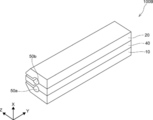
- FIG. 4 is a schematic perspective view showing a second embodiment of the die head according to the present disclosure.
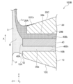
- FIG. 5 is a schematic cross-sectional view showing an example of a coating layer forming step using the second embodiment of the die head according to the present disclosure.
- the same components as those in the first embodiment are designated by the same reference numerals as those in the first embodiment, and detailed description thereof will be omitted.
- the second embodiment differs from the first embodiment in the following matters. That is, the die head according to the second embodiment has a third lip 40 in addition to the first lip 10 and the second lip 20.
- the die head 100B shown in FIGS. 4 and 5 is a die head for multi-layer coating.
- the die head 100B can discharge two types of coating liquids.
- the die head 100B has a first lip 10, a second lip 20, and a third lip 40. Further, in the coating layer forming step shown in FIG. 5, the first lip 10 corresponds to the most upstream side lip, and the second lip 20 corresponds to the most downstream side lip.
- the die head 100B is made of metal. Examples of the metal include stainless steel.
- the die head 100B may be formed of a plurality of metals.
- the tip of the first lip 10, the tip of the second lip 20, and the tip of the third lip 40 are cemented carbide (for example, TF15 (Mitsubishi Materials Co., Ltd.)) or cemented carbide.
- TF15 Mitsubishi Materials Co., Ltd.
- cemented carbide for example, TF15 (Mitsubishi Materials Co., Ltd.)
- cemented carbide for example, TF15 (Mitsubishi Materials Co., Ltd.)
- cemented carbide for example, TF15 (Mitsubishi Materials Co., Ltd.)
- cemented carbide for example, TF15 (Mitsubishi Materials Co., Ltd.)
- cemented carbide for example, TF15 (Mitsubishi Materials Co., Ltd.)
- cemented carbide for example, TF15 (Mitsubishi Materials Co., Ltd.)
- cemented carbide
- the third lip 40 is a member that defines the slot 30a and the slot 30b, respectively.
- the third lip 40 is arranged side by side in direction X along with the first lip 10 and the second lip 20.
- the third lip 40 is arranged between the first lip 10 and the second lip 20.
- the third lip 40 is formed of the above-mentioned metal.
- the shape of the third lip 40 is a columnar shape having the width direction Y as the length direction, and may have a recess for forming a manifold described later.
- the third lip 40 has a land surface 40A, a slot forming surface 40B 1, and a slot forming surface 40B 2 .
- each surface constituting the third lip 40 will be described.
- the land surface 40A is a surface facing the direction Z.
- the land surface 40A faces the surface of the base material F, which is the object to be coated, in the process of discharging the coating liquid L 1 and the coating liquid L 2 from the die head 100B, for example.
- the slot forming surface 40B 1 is a surface that defines the slot 30a together with the slot forming surface 10B of the first lip 10.
- the slot forming surface 40B 1 is connected to the land surface 40A on the opposite side of the slot forming surface 40B 2.
- the slot forming surface 40B 1 faces the slot forming surface 10B.
- the slot forming surface 40B 1 is a surface extending in the direction Z.
- the slot forming surface 40B 2 is a surface that defines the slot 30b together with the slot forming surface 20B of the second lip 20.
- the slot forming surface 40B 2 is connected to the land surface 40A on the opposite side of the slot forming surface 40B 1.
- the slot forming surface 40B 2 faces the slot forming surface 20B.
- the slot forming surface 40B 2 is a surface extending in the direction Z.
- Slot 30a is a space for transporting and discharging the coating liquid L 1.
- the slot 30a is formed between the first lip 10 and the third lip 40 that are adjacent to each other in the direction X. Specifically, the slot 30a is formed by the slot forming surface 10B of the first lip 10 and the slot forming surface 40B 1 of the third lip 40.
- Slot 30a extends in direction Z.
- the slot 30a communicates with the first manifold 50a.
- First manifold 50a is die head 100B in the longitudinal direction (i.e., Y direction in FIG. 4) is a space extending along the, coating solution L 1 which is supplied to the die head 100B coating width direction (i.e., die head 100B longitudinal and ⁇ the Y direction) in FIG. 4, for temporarily storing the application liquid L 1.
- the first manifold 50a is formed between the first lip 10 and the third lip 40.
- the slot 30b is a space for transferring and discharging the coating liquid L 2.
- the slot 30b is formed between the second lip 20 and the third lip 40 that are adjacent to each other in the direction X. Specifically, the slot 30b is formed by the slot forming surface 20B of the second lip 20 and the slot forming surface 40B 2 of the third lip 40.
- Slot 30b extends in direction Z.
- the slot 30b communicates with the second manifold 50b.
- the second manifold 50b is a space extending along the length direction of the die head 100B (that is, the Y direction in FIG. 4), and the coating liquid L 2 supplied to the die head 100B is applied in the coating width direction (that is, the die head 100B). (Y direction in FIG. 4), the coating liquid L 2 is temporarily stored.
- the second manifold 50b is formed between the second lip 20 and the third lip 40.
- the die head 100B has a land surface 10A of the first lip 10 and a second lip with respect to the base material F to be coated.
- the land surface 20A of the 20 and the land surface 40A of the third lip 40 are arranged so as to face each other.
- the die head 100B is on the lateral side of the backup roll 200 and is the first lip 10 from the viewpoint that the application is quick and the effect of suppressing the occurrence of coating defects can be efficiently obtained.
- Is preferably arranged so as to be located on the upstream side in the transport direction of the base material F.
- the distance between the land surface 40A of the third lip 40 and the base material F is not limited and is determined according to, for example, the viscosity of the coating liquid L 1 , the viscosity of the coating liquid L 2 , and the thickness of the coating film to be formed. do it.
- the distance between the land surface 40A of the third lip 40 and the base material F is in the range of 50 ⁇ m to 500 ⁇ m.
- the distance between the land surface 40A of the third lip 40 and the base material F may be determined, for example, in the range of 100 ⁇ m to 300 ⁇ m.
- the distance between the land surface 40A of the third lip 40 and the base material F is the distance between the land surface of the other lip (referred to as the first lip or the second lip; the same shall apply hereinafter in this paragraph) and the base material. It may be the same as the distance of.
- the distance between the land surface 40A of the third lip 40 and the base material F may be different from the distance between the land surface of the other lip and the base material F.
- the base material F is conveyed in the direction X with respect to the die head 100B.
- the coating solution L 1 which is supplied to the die head 100B is discharged through the slot 30a.
- the coating liquid L 2 supplied to the die head 100B is discharged through the slot 30b.
- the type of the coating liquid L 1 may be the same as or different from the type of the coating liquid L 2.
- the coating liquid L 1 and the coating liquid L 2 discharged from the die head 100A form a bead B between the die head 100B and the base material F.
- the coating liquids L 1 and L 2 forming the bead B move onto the base material F.
- a coating film can be formed on the base material F.
- the target coating is applied on the base material F to be coated by appropriately undergoing a necessary step (for example, a step of drying the coating film).
- a work layer is formed.
- the same method as the method for forming the coating layer to which the die head 100A is applied as described in the section of the above "first embodiment" is applied.
- the present disclosure is not limited to the above embodiments.
- the present disclosure includes embodiments in which the above embodiments are appropriately modified within the scope of the purposes of the present disclosure.
- a base material As a base material, a long triacetyl cellulose film (TD40UL, FUJIFILM Corporation, refractive index: 1.48, thickness: 60 ⁇ m, width: 1,340 mm) was prepared. Hereinafter, it is also referred to as TAC film.
- the coating liquid A was prepared by mixing the following components. -The following polymerizable liquid crystal compound L-9: 47.50 parts by mass-The following polymerizable liquid crystal compound L-10: 47.50 parts by mass-The following polymerizable liquid crystal compound L-3: 5.00 parts by mass-The following Polymerization initiator PI-1: 0.50 parts by mass ⁇ The following leveling agent T-1 (weight average molecular weight: 10,000): 0.20 parts by mass ⁇ Methyl ethyl ketone: 235.00 parts by mass
- one of R 1 and R 2 represents a methyl group and the other represents a hydrogen atom
- R 3 and R 4 represent one of them.
- the coating liquid B was prepared by mixing the following components. -The following liquid crystal polymer LP1 (weight average molecular weight: 13,300): 4.011 parts by mass-The following bicolor compound D1: 0.792 parts by mass-The following bicolor compound D2: 0.963 parts by mass ⁇
- the following interface improver F2 weight average molecular weight: 10,000
- the following interface improver F3 0.073 parts by mass ⁇
- the following interface improver F4 0.073 parts by mass ⁇ tetrahydrofuran (Organic solvent with a boiling point of 80 ° C or less): 37.6004 parts by mass ⁇ Cyclopentanone: 56.4006 parts by mass
- the liquid crystal polymer LP1 contains the structural unit (1) and the structural unit (2) in a molecule at a mass ratio of 80:20 ((1): (2)).
- IPA isopropanol, 500 parts by mass
- partially caprolactone-modified polyfunctional acrylate (KAYARAD DPCA-20, Nippon Kayaku Co., Ltd., 750 parts by mass)
- silica sol (MIBK-ST,) with respect to methyl ethyl ketone (500 parts by mass).
- a photopolymerization initiator Omnirad 184, IGM Resins BV, 50 parts by mass
- Glutaraldehyde bridge agent, 1 part by mass
- water 378 parts by mass
- methanol 120 parts by mass
- PVA modified polyvinyl alcohol
- the numerical value added to each structural unit of the main chain is the molar ratio.
- a die head a having the same configuration as the die head 100A shown in FIG. 3 was produced.
- the die head a is provided with a convex curved surface 12 having a radius of curvature of 0.4 mm at a portion of the outer surface 10C of the first lip 10 connected to the land surface 10A.
- a surf containing a fluorine-containing compound also referred to as an F-based compound with respect to the land surface 10A and the outer surface 10C of the first lip 10 and the land surface 20A and the outer surface 20C of the second lip 20 of the die head a.
- a die head b having the same configuration as the die head a was produced except that a convex curved surface 12 having a radius of curvature of 0.5 mm was provided at a portion of the outer surface 10C of the first lip 10 connected to the land surface 10A.
- the die head b was surface-treated in the same manner as the preparation of the die head 1 to obtain a die head 2.
- the dynamic contact angle hysteresis of the surface layer of the die head 2 due to methyl ethyl ketone was measured by the method described above and found to be 18 °. Further, the surface layer Rzjis was measured by the method described above and found to be 1.1 ⁇ m.
- the die head c was surface-treated in the same manner as the preparation of the die head 1 to obtain a die head 3.
- the dynamic contact angle hysteresis of the surface layer of the die head 3 due to methyl ethyl ketone was measured by the method described above and found to be 15 °. Further, the surface layer Rzjis was measured by the method described above and found to be 0.9 ⁇ m.
- a die head d having the same configuration as the die head 100C shown in FIG. 5 was produced.
- the die head d is provided with a convex curved surface 12 having a radius of curvature of 0.4 mm at a portion of the outer surface 10C of the first lip 10 connected to the land surface 10A.
- Fluorine-containing compound with respect to the land surface 10A and outer surface 10C of the first lip 10, the land surface 20A and outer surface 20C of the second lip 20, and the land surface 40A of the third lip 40 of the die head d.
- the die head 5 was produced in the same manner as the die head 1 except that the surface treatment was changed to the following method. That is, with respect to the land surface 10A and the outer surface 10C of the first lip 10 and the land surface 20A and the outer surface 20C of the second lip 20 of the die head a, a tetrafluoroethylene resin (F-based resin) manufactured by DuPont. Fluororesin coating was performed using (also referred to as). Further, the surface layer Rzjis obtained as described above was measured by the method described above and found to be 1.1 ⁇ m.
- F-based resin tetrafluoroethylene resin
- the die head 6 was produced in the same manner as the die head 1 except that the surface treatment was changed to the following method. That is, the land surface 10A and the outer surface 10C of the first lip 10 and the land surface 20A and the outer surface 20C of the second lip 20 of the die head a are electrolessly plated with nickel and polytetrafluoroethylene. A composite plating layer (also referred to as F-based plating) was formed. Further, the surface layer Rzjis obtained as described above was measured by the method described above and found to be 1.1 ⁇ m.
- a die head e having the same configuration as the die head a was produced except that the portion of the outer surface 10C of the first lip 10 connected to the land surface 10A was a flat surface.
- the die head e was surface-treated in the same manner as the preparation of the die head 1 to obtain a die head 7.
- the dynamic contact angle hysteresis of the surface layer of the die head 7 due to methyl ethyl ketone was measured by the method described above and found to be 18 °. Further, the surface layer Rzjis was measured by the method described above and found to be 1.1 ⁇ m.
- Example 1 The die head 1 was arranged as shown in FIG. 1, and the coating liquid A was applied onto the TAC film to form a coating film having a width of 200 mm. Specifically, the TAC film is conveyed on a backup roll having a surface temperature of 60 ° C. and an outer diameter of 300 mm, wound around the backup roll, and the side of the backup roll with respect to the conveyed TAC film. The coating liquid A was applied using the die head 1 arranged in. When the coating liquid A was applied, the lap angle of the TAC film was 150 °. The transport speed of the TAC film was 30 m / min. When the coating liquid A was applied, the distance between the land surface 10A of the first lip 10 and the TAC film was 100 ⁇ m, and the distance between the land surface 20A of the second lip 20 and the TAC film was 100 ⁇ m. ..
- Examples 2 to 4> A coating film was formed by the same procedure as in Example 1 except that the type of coating liquid was changed according to the description in Table 1.
- the coating streaks 1 caused by the most upstream lip that is, the first lip
- the coating streaks 2 caused by the most downstream lip that is, the second lip
Landscapes
- Coating Apparatus (AREA)
Priority Applications (3)
| Application Number | Priority Date | Filing Date | Title |
|---|---|---|---|
| KR1020227029047A KR102693598B1 (ko) | 2020-03-11 | 2021-02-26 | 다이 헤드 |
| JP2022505915A JP7266746B2 (ja) | 2020-03-11 | 2021-02-26 | ダイヘッド |
| CN202180017103.7A CN115175772B (zh) | 2020-03-11 | 2021-02-26 | 模头 |
Applications Claiming Priority (2)
| Application Number | Priority Date | Filing Date | Title |
|---|---|---|---|
| JP2020-042282 | 2020-03-11 | ||
| JP2020042282 | 2020-03-11 |
Publications (1)
| Publication Number | Publication Date |
|---|---|
| WO2021182132A1 true WO2021182132A1 (ja) | 2021-09-16 |
Family
ID=77671444
Family Applications (1)
| Application Number | Title | Priority Date | Filing Date |
|---|---|---|---|
| PCT/JP2021/007360 Ceased WO2021182132A1 (ja) | 2020-03-11 | 2021-02-26 | ダイヘッド |
Country Status (4)
| Country | Link |
|---|---|
| JP (1) | JP7266746B2 (https=) |
| KR (1) | KR102693598B1 (https=) |
| CN (1) | CN115175772B (https=) |
| WO (1) | WO2021182132A1 (https=) |
Citations (3)
| Publication number | Priority date | Publication date | Assignee | Title |
|---|---|---|---|---|
| JP2002248399A (ja) * | 2001-02-27 | 2002-09-03 | Toray Ind Inc | 塗布部材の製造方法及び装置 |
| JP2004216298A (ja) * | 2003-01-16 | 2004-08-05 | Mitsubishi Chemicals Corp | 塗布方法およびスリットダイノズル |
| JP2016068047A (ja) * | 2014-09-30 | 2016-05-09 | 大日本印刷株式会社 | ダイコート装置および透明導電基材の製造方法 |
Family Cites Families (13)
| Publication number | Priority date | Publication date | Assignee | Title |
|---|---|---|---|---|
| US5998549A (en) * | 1996-05-31 | 1999-12-07 | 3M Innovative Properties Company | Durable, low surface energy compounds and articles, apparatuses, and methods for using the same |
| JP2003266001A (ja) * | 2002-03-15 | 2003-09-24 | Seiko Epson Corp | 成膜装置、デバイスの製造方法及び電子機器 |
| JP4353681B2 (ja) * | 2002-07-18 | 2009-10-28 | 大日本印刷株式会社 | 塗工用ダイヘッド |
| JP2005040979A (ja) * | 2003-07-22 | 2005-02-17 | Seiko Epson Corp | 液滴吐出ヘッド、液滴吐出装置、及び機能性膜 |
| JP2007144362A (ja) * | 2005-11-30 | 2007-06-14 | Toppan Printing Co Ltd | ダイヘッドの製造方法 |
| BRPI0819558A2 (pt) | 2007-12-31 | 2015-05-05 | 3M Innovative Properties Co | "método para aplicação de um material revestidor" |
| JP5220667B2 (ja) * | 2009-03-25 | 2013-06-26 | 株式会社日本触媒 | マイクロカプセル含有塗料の塗工方法、塗工装置、および該塗工方法により製造された塗工シート |
| JP5621310B2 (ja) | 2010-05-06 | 2014-11-12 | 東洋紡株式会社 | 溶液製膜用コーティングダイおよび溶液製膜方法 |
| JP2014026107A (ja) | 2012-07-26 | 2014-02-06 | Asahi Kasei E-Materials Corp | 感光性エレメントの製造方法 |
| KR102182155B1 (ko) * | 2013-09-30 | 2020-11-24 | 미쯔비시 케미컬 주식회사 | 이방성 색소막의 제조 방법, 그 제조 방법에 의해 제조된 이방성 색소막, 그 이방성 색소막을 포함하는 광학 소자, 및 그 광학 소자를 포함하는 액정 소자 |
| JP2017148763A (ja) | 2016-02-26 | 2017-08-31 | 東レ株式会社 | 塗布装置、塗布方法、及びそれを用いた積層フィルムの製造方法 |
| JP2018134576A (ja) * | 2017-02-21 | 2018-08-30 | 東レフィルム加工株式会社 | 塗布装置、塗布方法、およびそれらを用いた積層フィルムの製造方法 |
| JP2018183762A (ja) | 2017-04-27 | 2018-11-22 | 株式会社ヒラノテクシード | 塗工装置及びその塗工方法 |
-
2021
- 2021-02-26 JP JP2022505915A patent/JP7266746B2/ja active Active
- 2021-02-26 CN CN202180017103.7A patent/CN115175772B/zh active Active
- 2021-02-26 WO PCT/JP2021/007360 patent/WO2021182132A1/ja not_active Ceased
- 2021-02-26 KR KR1020227029047A patent/KR102693598B1/ko active Active
Patent Citations (3)
| Publication number | Priority date | Publication date | Assignee | Title |
|---|---|---|---|---|
| JP2002248399A (ja) * | 2001-02-27 | 2002-09-03 | Toray Ind Inc | 塗布部材の製造方法及び装置 |
| JP2004216298A (ja) * | 2003-01-16 | 2004-08-05 | Mitsubishi Chemicals Corp | 塗布方法およびスリットダイノズル |
| JP2016068047A (ja) * | 2014-09-30 | 2016-05-09 | 大日本印刷株式会社 | ダイコート装置および透明導電基材の製造方法 |
Also Published As
| Publication number | Publication date |
|---|---|
| JP7266746B2 (ja) | 2023-04-28 |
| CN115175772A (zh) | 2022-10-11 |
| KR102693598B1 (ko) | 2024-08-08 |
| JPWO2021182132A1 (https=) | 2021-09-16 |
| CN115175772B (zh) | 2024-06-18 |
| KR20220126298A (ko) | 2022-09-15 |
Similar Documents
| Publication | Publication Date | Title |
|---|---|---|
| US7713579B2 (en) | Coating apparatus, coating method, and method for manufacturing optical film | |
| CN100460896C (zh) | 光学薄膜和抗反射薄膜的生产方法,光学薄膜、抗反射薄膜、偏振片以及包含它们的图像显示装置 | |
| US20080250955A1 (en) | Fluoropolymer Film Made by Printing | |
| JP2003222704A (ja) | 反射防止フィルム、偏光板およびディスプレイ装置 | |
| JP7270757B2 (ja) | ダイヘッド | |
| WO2021182132A1 (ja) | ダイヘッド | |
| JP6968290B2 (ja) | 積層体の製造方法 | |
| JP7273242B2 (ja) | ダイヘッド | |
| JP2022502246A (ja) | 基板を処理する装置及び方法 | |
| JP4828191B2 (ja) | 塗布方法、装置、光学フィルムの製造方法、及び反射防止フィルムの製造方法 | |
| WO2017122561A1 (ja) | 滑水性コート材料 | |
| JP2006072320A (ja) | 反射防止フィルムの製造方法、反射防止フィルム、偏光板、および画像表示装置 | |
| JP4759283B2 (ja) | 光学機能層の製造方法 | |
| JP2023085992A (ja) | ダイヘッド及び塗膜の製造方法 | |
| JP5322478B2 (ja) | スロットダイコーター及び塗工方法 | |
| JP2017148763A (ja) | 塗布装置、塗布方法、及びそれを用いた積層フィルムの製造方法 | |
| WO2021246336A1 (ja) | ダイヘッド | |
| JP5087230B2 (ja) | 塗布方法及び光学フィルムの製造方法 | |
| JP2006272130A (ja) | 塗布液の塗布方法、塗布液の塗布装置、光学フィルム、および反射防止フィルム | |
| JP2006285221A (ja) | 反射防止フィルム、反射防止フィルムの製造方法、偏光板、それを用いた画像表示装置 | |
| JP2007268384A (ja) | 塗布装置、塗布方法、および光学フィルムの製造方法 | |
| JP5899916B2 (ja) | 薄膜の形成方法 |
Legal Events
| Date | Code | Title | Description |
|---|---|---|---|
| 121 | Ep: the epo has been informed by wipo that ep was designated in this application |
Ref document number: 21768231 Country of ref document: EP Kind code of ref document: A1 |
|
| ENP | Entry into the national phase |
Ref document number: 2022505915 Country of ref document: JP Kind code of ref document: A |
|
| ENP | Entry into the national phase |
Ref document number: 20227029047 Country of ref document: KR Kind code of ref document: A |
|
| NENP | Non-entry into the national phase |
Ref country code: DE |
|
| 122 | Ep: pct application non-entry in european phase |
Ref document number: 21768231 Country of ref document: EP Kind code of ref document: A1 |