WO2021171715A1 - 熱交換器の流路構造、及び熱交換器 - Google Patents
熱交換器の流路構造、及び熱交換器 Download PDFInfo
- Publication number
- WO2021171715A1 WO2021171715A1 PCT/JP2020/043467 JP2020043467W WO2021171715A1 WO 2021171715 A1 WO2021171715 A1 WO 2021171715A1 JP 2020043467 W JP2020043467 W JP 2020043467W WO 2021171715 A1 WO2021171715 A1 WO 2021171715A1
- Authority
- WO
- WIPO (PCT)
- Prior art keywords
- heat exchanger
- inner cylinder
- outer cylinder
- flow path
- cylinder
- Prior art date
Links
- 239000012530 fluid Substances 0.000 claims abstract description 97
- 238000011084 recovery Methods 0.000 claims abstract description 46
- 230000002093 peripheral effect Effects 0.000 claims description 51
- 238000011144 upstream manufacturing Methods 0.000 claims description 42
- 238000004891 communication Methods 0.000 claims description 21
- 238000005192 partition Methods 0.000 claims description 15
- 238000000638 solvent extraction Methods 0.000 claims 1
- 239000000463 material Substances 0.000 description 20
- 229910052751 metal Inorganic materials 0.000 description 13
- 239000002184 metal Substances 0.000 description 13
- 238000000034 method Methods 0.000 description 12
- 239000003054 catalyst Substances 0.000 description 10
- 239000000919 ceramic Substances 0.000 description 7
- 230000004323 axial length Effects 0.000 description 6
- 239000007789 gas Substances 0.000 description 5
- 239000010935 stainless steel Substances 0.000 description 4
- 229910001220 stainless steel Inorganic materials 0.000 description 4
- 238000003466 welding Methods 0.000 description 4
- 239000000498 cooling water Substances 0.000 description 3
- 230000007423 decrease Effects 0.000 description 3
- 238000010304 firing Methods 0.000 description 3
- 238000004519 manufacturing process Methods 0.000 description 3
- 230000008646 thermal stress Effects 0.000 description 3
- 229910000838 Al alloy Inorganic materials 0.000 description 2
- 229910001369 Brass Inorganic materials 0.000 description 2
- 229910000881 Cu alloy Inorganic materials 0.000 description 2
- XEEYBQQBJWHFJM-UHFFFAOYSA-N Iron Chemical compound [Fe] XEEYBQQBJWHFJM-UHFFFAOYSA-N 0.000 description 2
- PXHVJJICTQNCMI-UHFFFAOYSA-N Nickel Chemical compound [Ni] PXHVJJICTQNCMI-UHFFFAOYSA-N 0.000 description 2
- KDLHZDBZIXYQEI-UHFFFAOYSA-N Palladium Chemical compound [Pd] KDLHZDBZIXYQEI-UHFFFAOYSA-N 0.000 description 2
- 229910052772 Samarium Inorganic materials 0.000 description 2
- 229910001069 Ti alloy Inorganic materials 0.000 description 2
- MCMNRKCIXSYSNV-UHFFFAOYSA-N Zirconium dioxide Chemical compound O=[Zr]=O MCMNRKCIXSYSNV-UHFFFAOYSA-N 0.000 description 2
- 230000005540 biological transmission Effects 0.000 description 2
- 239000010951 brass Substances 0.000 description 2
- 238000005219 brazing Methods 0.000 description 2
- 238000006555 catalytic reaction Methods 0.000 description 2
- 239000004927 clay Substances 0.000 description 2
- 238000009792 diffusion process Methods 0.000 description 2
- 230000000694 effects Effects 0.000 description 2
- 239000000446 fuel Substances 0.000 description 2
- 238000005470 impregnation Methods 0.000 description 2
- 238000005304 joining Methods 0.000 description 2
- 239000007788 liquid Substances 0.000 description 2
- BASFCYQUMIYNBI-UHFFFAOYSA-N platinum Chemical compound [Pt] BASFCYQUMIYNBI-UHFFFAOYSA-N 0.000 description 2
- 239000000843 powder Substances 0.000 description 2
- 230000001737 promoting effect Effects 0.000 description 2
- KZUNJOHGWZRPMI-UHFFFAOYSA-N samarium atom Chemical compound [Sm] KZUNJOHGWZRPMI-UHFFFAOYSA-N 0.000 description 2
- 239000007787 solid Substances 0.000 description 2
- 239000000126 substance Substances 0.000 description 2
- 238000009423 ventilation Methods 0.000 description 2
- RYGMFSIKBFXOCR-UHFFFAOYSA-N Copper Chemical compound [Cu] RYGMFSIKBFXOCR-UHFFFAOYSA-N 0.000 description 1
- FYYHWMGAXLPEAU-UHFFFAOYSA-N Magnesium Chemical compound [Mg] FYYHWMGAXLPEAU-UHFFFAOYSA-N 0.000 description 1
- KJTLSVCANCCWHF-UHFFFAOYSA-N Ruthenium Chemical compound [Ru] KJTLSVCANCCWHF-UHFFFAOYSA-N 0.000 description 1
- BQCADISMDOOEFD-UHFFFAOYSA-N Silver Chemical compound [Ag] BQCADISMDOOEFD-UHFFFAOYSA-N 0.000 description 1
- ATJFFYVFTNAWJD-UHFFFAOYSA-N Tin Chemical compound [Sn] ATJFFYVFTNAWJD-UHFFFAOYSA-N 0.000 description 1
- RTAQQCXQSZGOHL-UHFFFAOYSA-N Titanium Chemical compound [Ti] RTAQQCXQSZGOHL-UHFFFAOYSA-N 0.000 description 1
- HCHKCACWOHOZIP-UHFFFAOYSA-N Zinc Chemical compound [Zn] HCHKCACWOHOZIP-UHFFFAOYSA-N 0.000 description 1
- QCWXUUIWCKQGHC-UHFFFAOYSA-N Zirconium Chemical compound [Zr] QCWXUUIWCKQGHC-UHFFFAOYSA-N 0.000 description 1
- 230000003213 activating effect Effects 0.000 description 1
- 229910052782 aluminium Inorganic materials 0.000 description 1
- XAGFODPZIPBFFR-UHFFFAOYSA-N aluminium Chemical compound [Al] XAGFODPZIPBFFR-UHFFFAOYSA-N 0.000 description 1
- PNEYBMLMFCGWSK-UHFFFAOYSA-N aluminium oxide Inorganic materials [O-2].[O-2].[O-2].[Al+3].[Al+3] PNEYBMLMFCGWSK-UHFFFAOYSA-N 0.000 description 1
- 229910052788 barium Inorganic materials 0.000 description 1
- DSAJWYNOEDNPEQ-UHFFFAOYSA-N barium atom Chemical compound [Ba] DSAJWYNOEDNPEQ-UHFFFAOYSA-N 0.000 description 1
- 239000011230 binding agent Substances 0.000 description 1
- 229910052797 bismuth Inorganic materials 0.000 description 1
- JCXGWMGPZLAOME-UHFFFAOYSA-N bismuth atom Chemical compound [Bi] JCXGWMGPZLAOME-UHFFFAOYSA-N 0.000 description 1
- 238000009835 boiling Methods 0.000 description 1
- CETPSERCERDGAM-UHFFFAOYSA-N ceric oxide Chemical compound O=[Ce]=O CETPSERCERDGAM-UHFFFAOYSA-N 0.000 description 1
- 229910000422 cerium(IV) oxide Inorganic materials 0.000 description 1
- 238000006243 chemical reaction Methods 0.000 description 1
- 229910017052 cobalt Inorganic materials 0.000 description 1
- 239000010941 cobalt Substances 0.000 description 1
- GUTLYIVDDKVIGB-UHFFFAOYSA-N cobalt atom Chemical compound [Co] GUTLYIVDDKVIGB-UHFFFAOYSA-N 0.000 description 1
- 239000002131 composite material Substances 0.000 description 1
- 229910052802 copper Inorganic materials 0.000 description 1
- 239000010949 copper Substances 0.000 description 1
- 230000006866 deterioration Effects 0.000 description 1
- 238000007599 discharging Methods 0.000 description 1
- PCHJSUWPFVWCPO-UHFFFAOYSA-N gold Chemical compound [Au] PCHJSUWPFVWCPO-UHFFFAOYSA-N 0.000 description 1
- 229910052737 gold Inorganic materials 0.000 description 1
- 239000010931 gold Substances 0.000 description 1
- 238000005338 heat storage Methods 0.000 description 1
- 238000010438 heat treatment Methods 0.000 description 1
- 229910052738 indium Inorganic materials 0.000 description 1
- APFVFJFRJDLVQX-UHFFFAOYSA-N indium atom Chemical compound [In] APFVFJFRJDLVQX-UHFFFAOYSA-N 0.000 description 1
- 239000011261 inert gas Substances 0.000 description 1
- 229910052742 iron Inorganic materials 0.000 description 1
- 229910052749 magnesium Inorganic materials 0.000 description 1
- 239000011777 magnesium Substances 0.000 description 1
- WPBNNNQJVZRUHP-UHFFFAOYSA-L manganese(2+);methyl n-[[2-(methoxycarbonylcarbamothioylamino)phenyl]carbamothioyl]carbamate;n-[2-(sulfidocarbothioylamino)ethyl]carbamodithioate Chemical compound [Mn+2].[S-]C(=S)NCCNC([S-])=S.COC(=O)NC(=S)NC1=CC=CC=C1NC(=S)NC(=O)OC WPBNNNQJVZRUHP-UHFFFAOYSA-L 0.000 description 1
- 150000002736 metal compounds Chemical class 0.000 description 1
- 229910044991 metal oxide Inorganic materials 0.000 description 1
- 150000004706 metal oxides Chemical class 0.000 description 1
- 239000000203 mixture Substances 0.000 description 1
- 239000010705 motor oil Substances 0.000 description 1
- 238000000465 moulding Methods 0.000 description 1
- 229910052759 nickel Inorganic materials 0.000 description 1
- 229910052758 niobium Inorganic materials 0.000 description 1
- 239000010955 niobium Substances 0.000 description 1
- GUCVJGMIXFAOAE-UHFFFAOYSA-N niobium atom Chemical compound [Nb] GUCVJGMIXFAOAE-UHFFFAOYSA-N 0.000 description 1
- 229910000510 noble metal Inorganic materials 0.000 description 1
- 239000003960 organic solvent Substances 0.000 description 1
- 229910052763 palladium Inorganic materials 0.000 description 1
- 229910052697 platinum Inorganic materials 0.000 description 1
- 239000010970 precious metal Substances 0.000 description 1
- 238000000746 purification Methods 0.000 description 1
- 229910052703 rhodium Inorganic materials 0.000 description 1
- 239000010948 rhodium Substances 0.000 description 1
- MHOVAHRLVXNVSD-UHFFFAOYSA-N rhodium atom Chemical compound [Rh] MHOVAHRLVXNVSD-UHFFFAOYSA-N 0.000 description 1
- 229910052707 ruthenium Inorganic materials 0.000 description 1
- 229910052709 silver Inorganic materials 0.000 description 1
- 239000004332 silver Substances 0.000 description 1
- 125000006850 spacer group Chemical group 0.000 description 1
- 229910052718 tin Inorganic materials 0.000 description 1
- 239000011135 tin Substances 0.000 description 1
- 229910052719 titanium Inorganic materials 0.000 description 1
- 239000010936 titanium Substances 0.000 description 1
- XLYOFNOQVPJJNP-UHFFFAOYSA-N water Substances O XLYOFNOQVPJJNP-UHFFFAOYSA-N 0.000 description 1
- 229910052725 zinc Inorganic materials 0.000 description 1
- 239000011701 zinc Substances 0.000 description 1
- 229910052726 zirconium Inorganic materials 0.000 description 1
Images


Classifications
-
- F—MECHANICAL ENGINEERING; LIGHTING; HEATING; WEAPONS; BLASTING
- F01—MACHINES OR ENGINES IN GENERAL; ENGINE PLANTS IN GENERAL; STEAM ENGINES
- F01N—GAS-FLOW SILENCERS OR EXHAUST APPARATUS FOR MACHINES OR ENGINES IN GENERAL; GAS-FLOW SILENCERS OR EXHAUST APPARATUS FOR INTERNAL COMBUSTION ENGINES
- F01N13/00—Exhaust or silencing apparatus characterised by constructional features ; Exhaust or silencing apparatus, or parts thereof, having pertinent characteristics not provided for in, or of interest apart from, groups F01N1/00 - F01N5/00, F01N9/00, F01N11/00
- F01N13/08—Other arrangements or adaptations of exhaust conduits
-
- F—MECHANICAL ENGINEERING; LIGHTING; HEATING; WEAPONS; BLASTING
- F01—MACHINES OR ENGINES IN GENERAL; ENGINE PLANTS IN GENERAL; STEAM ENGINES
- F01N—GAS-FLOW SILENCERS OR EXHAUST APPARATUS FOR MACHINES OR ENGINES IN GENERAL; GAS-FLOW SILENCERS OR EXHAUST APPARATUS FOR INTERNAL COMBUSTION ENGINES
- F01N3/00—Exhaust or silencing apparatus having means for purifying, rendering innocuous, or otherwise treating exhaust
- F01N3/08—Exhaust or silencing apparatus having means for purifying, rendering innocuous, or otherwise treating exhaust for rendering innocuous
- F01N3/10—Exhaust or silencing apparatus having means for purifying, rendering innocuous, or otherwise treating exhaust for rendering innocuous by thermal or catalytic conversion of noxious components of exhaust
- F01N3/24—Exhaust or silencing apparatus having means for purifying, rendering innocuous, or otherwise treating exhaust for rendering innocuous by thermal or catalytic conversion of noxious components of exhaust characterised by constructional aspects of converting apparatus
-
- F—MECHANICAL ENGINEERING; LIGHTING; HEATING; WEAPONS; BLASTING
- F01—MACHINES OR ENGINES IN GENERAL; ENGINE PLANTS IN GENERAL; STEAM ENGINES
- F01N—GAS-FLOW SILENCERS OR EXHAUST APPARATUS FOR MACHINES OR ENGINES IN GENERAL; GAS-FLOW SILENCERS OR EXHAUST APPARATUS FOR INTERNAL COMBUSTION ENGINES
- F01N5/00—Exhaust or silencing apparatus combined or associated with devices profiting by exhaust energy
- F01N5/02—Exhaust or silencing apparatus combined or associated with devices profiting by exhaust energy the devices using heat
-
- F—MECHANICAL ENGINEERING; LIGHTING; HEATING; WEAPONS; BLASTING
- F28—HEAT EXCHANGE IN GENERAL
- F28D—HEAT-EXCHANGE APPARATUS, NOT PROVIDED FOR IN ANOTHER SUBCLASS, IN WHICH THE HEAT-EXCHANGE MEDIA DO NOT COME INTO DIRECT CONTACT
- F28D1/00—Heat-exchange apparatus having stationary conduit assemblies for one heat-exchange medium only, the media being in contact with different sides of the conduit wall, in which the other heat-exchange medium is a large body of fluid, e.g. domestic or motor car radiators
- F28D1/06—Heat-exchange apparatus having stationary conduit assemblies for one heat-exchange medium only, the media being in contact with different sides of the conduit wall, in which the other heat-exchange medium is a large body of fluid, e.g. domestic or motor car radiators with the heat-exchange conduits forming part of, or being attached to, the tank containing the body of fluid
-
- F—MECHANICAL ENGINEERING; LIGHTING; HEATING; WEAPONS; BLASTING
- F28—HEAT EXCHANGE IN GENERAL
- F28D—HEAT-EXCHANGE APPARATUS, NOT PROVIDED FOR IN ANOTHER SUBCLASS, IN WHICH THE HEAT-EXCHANGE MEDIA DO NOT COME INTO DIRECT CONTACT
- F28D7/00—Heat-exchange apparatus having stationary tubular conduit assemblies for both heat-exchange media, the media being in contact with different sides of a conduit wall
- F28D7/10—Heat-exchange apparatus having stationary tubular conduit assemblies for both heat-exchange media, the media being in contact with different sides of a conduit wall the conduits being arranged one within the other, e.g. concentrically
Definitions
- the present invention relates to a flow path structure of a heat exchanger and a heat exchanger.
- the heat exchanger is a device that exchanges heat between the first fluid and the second fluid by circulating the first fluid inside and the second fluid outside.
- heat can be effectively utilized by exchanging heat from a high-temperature fluid (for example, exhaust gas) to a low-temperature fluid (for example, cooling water).
- a heat collecting portion including a honeycomb structure having a plurality of cells through which a first fluid (for example, exhaust gas) can flow and a heat collecting portion are arranged so as to cover the outer peripheral surface of the heat collecting portion to collect heat.
- Patent Document 2 includes heat including a covering member (inner cylinder) that covers the outer peripheral wall of the columnar honeycomb structure and a frame (outer cylinder) that forms a flow path of a second fluid between the covering member. Exchanges have been proposed.
- the present invention has been made to solve the above problems, and can suppress stagnation around the joints of the supply pipe and the discharge pipe of the second fluid flowing between the first inner cylinder and the outer cylinder. It is an object of the present invention to provide a flow path structure of a heat exchanger and a heat exchanger having the flow path structure.
- the present inventors have adjusted the flow of the second fluid to the joint of the outer cylinder to which at least one of the supply pipe and the discharge pipe is joined. It has been found that the flow of the second fluid around the supply pipe and the discharge pipe can be improved by providing the portion, and the present invention has been completed.
- the first inner cylinder capable of circulating the first fluid and accommodating the heat recovery member and the first inner cylinder
- An outer cylinder arranged at a distance outside in the radial direction of the first inner cylinder so that a second fluid can flow between the first inner cylinder and the outer cylinder.
- the second fluid supply pipe and the discharge pipe joined to the outer cylinder are provided.
- the outer cylinder is a flow path structure of a heat exchanger having a flow adjusting portion for adjusting the flow of the second fluid at at least one joint of the supply pipe and the discharge pipe.
- the present invention is a heat exchanger including a flow path structure of the heat exchanger and a heat recovery member housed in the first inner cylinder.
- a flow path structure of a heat exchanger capable of suppressing stagnation around a joint of a second fluid supply pipe and a discharge pipe flowing between the first inner cylinder and the outer cylinder, and a heat exchanger are provided. Can be provided.
- FIG. 5 is a cross-sectional view parallel to the flow direction of the first fluid of the heat exchanger including the flow path structure of the heat exchanger and the heat recovery member of FIG. It is a perspective view of the flow path structure of the heat exchanger which has another structure which concerns on Embodiment 1 of this invention. It is a perspective view of the flow path structure of the heat exchanger which has another structure which concerns on Embodiment 1 of this invention. It is a perspective view of the flow path structure of the heat exchanger which has another structure which concerns on Embodiment 1 of this invention. It is a perspective view of the flow path structure of the heat exchanger which has another structure which concerns on Embodiment 1 of this invention.
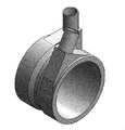
- FIG. 1 is a perspective view of the flow path structure of the heat exchanger according to the first embodiment of the present invention.
- FIG. 2 is a cross-sectional view parallel to the flow direction of the first fluid of the heat exchanger provided with the flow path structure of the heat exchanger of FIG. 1 and the heat recovery member (cross-sectional view of lines AA'in FIG. 1).
- FIGS. 3 to 8 are perspective views of a flow path structure of a heat exchanger having another structure according to the first embodiment of the present invention.
- the outer cylinder 20 arranged at intervals on the radial outer side of the first inner cylinder 10 so that the second fluid can flow, and a second fluid supply pipe 21 and a discharge pipe joined to the outer cylinder 20. 22 and. Further, the outer cylinder 20 has a flow adjusting portion 30 for adjusting the flow of the second fluid at at least one joint portion of the supply pipe 21 and the discharge pipe 22.
- the first inner cylinder 10 and the outer cylinder 20 are connected by the upstream side connecting member 50 and the downstream side connecting member 60, but the upstream side and the downstream side of the first inner cylinder 10 are connected.
- the first inner cylinder 10 and the outer cylinder 20 may be directly connected by increasing the diameter and / or reducing the diameter of the upstream side and the downstream side of the outer cylinder 20.
- the heat exchanger according to the first embodiment of the present invention includes the above-mentioned flow path structure of the heat exchanger and the heat recovery member 40 housed in the first inner cylinder 10.
- FIGS. 1 to 8 show an example in which the flow adjusting portion 30 is provided at the joint portion of both the supply pipe 21 and the discharge pipe 22, one of the joint portion of the supply pipe 21 or the discharge pipe 22 is provided.
- the flow adjusting unit 30 may be provided.
- the supply pipe 21 and the discharge pipe 22 are directly joined to the outer cylinder 20, the second fluid stagnates and boils around the joint portion of the supply pipe 21 and the discharge pipe 22. Therefore, the following problems (1) to (3) may occur.
- the structure of the flow adjusting unit 30 is not particularly limited as long as it can adjust the flow of the second fluid, but as shown in FIGS. 1 and 3 to 8, a part of the outer cylinder 20 in the outer peripheral direction. It is preferable to have a structure that is provided in the outer cylinder 20 and extends outward in the radial direction of the outer cylinder 20. With such a structure, the stagnation of the second fluid around the joint between the supply pipe 21 and the discharge pipe 22 can be stably suppressed.
- the flow adjusting unit 30 has at least one plane region 31 and a joint portion of the supply pipe 21 and / or the discharge pipe 22 is provided in the plane region 31 (FIGS. 1 and 3 to 8). With such a configuration, the supply pipe 21 and / or the discharge pipe 22 can be easily joined to the flow adjusting unit 30.
- the plane region 31 preferably includes a first plane region 31a parallel to the tangent plane of the outer peripheral surface of the outer cylinder 20 and / or a second plane region 31b perpendicular to the axial direction of the outer cylinder 20 (FIGS. 1 and 3 to 3). 8).
- the supply pipe 21 and / or the discharge pipe 22 can be joined in a direction perpendicular to and / or parallel to the axial direction of the outer cylinder 20.
- the outer cylinder 20 preferably has a flow adjusting portion 30 at the joint portion of both the supply pipe 21 and the discharge pipe 22 (FIGS. 1 and 3 to 8). With such a configuration, the stagnation of the second fluid around the joints of both the supply pipe 21 and the discharge pipe 22 is suppressed, so that the flow adjusting unit is connected to one of the joints of the supply pipe 21 and the discharge pipe 22.
- the heat exchange performance can be improved as compared with the case of having 30.
- the joints of both the supply pipe 21 and the discharge pipe 22 can be provided in the first plane region 31a of the flow adjusting portion 30 parallel to the tangent plane of the outer peripheral surface of the outer cylinder 20 (FIGS. 1 and 3 to 6). With such a configuration, when the connection destinations of the supply pipe 21 and the discharge pipe 22 are located in the direction perpendicular to the axial direction of the outer cylinder 20, the directions of the supply pipe 21 and the discharge pipe 22 (particularly, The axial direction at the joint between the supply pipe 21 and the discharge pipe 22) can be directed in that direction.
- both the supply pipe 21 and the discharge pipe 22 are provided in the first plane region 31a of the flow adjusting portion 30 parallel to the tangent plane of the outer peripheral surface of the outer cylinder 20, both the supply pipe 21 and the discharge pipe 22 are joined.
- the portions are preferably located on the same plane (FIGS. 1 and 4). With such a configuration, the axial direction at the joint portion of the supply pipe 21 and the discharge pipe 22 can be made the same direction.
- the supply pipe 21 is provided on the second end surface 23b side of the outer cylinder 20 and the discharge pipe 22 is provided on the first end surface 23a of the outer cylinder 20. It is preferable that the joint portion of the supply pipe 21 and the joint portion of the discharge pipe 22 provided on the side are located diagonally on the same plane (FIG. 4). With such a configuration, the axial direction at the joint portion of the supply pipe 21 and the discharge pipe 22 becomes a direction perpendicular to the axial direction of the outer cylinder 20. Further, the flow of the second fluid flowing between the first inner cylinder 10 and the outer cylinder 20 can be smoothed.
- the joints of both the supply pipe 21 and the discharge pipe 22 can be provided in the second plane region 31b of the flow adjusting portion 30 perpendicular to the axial direction of the outer cylinder 20 (FIG. 8).
- the axial direction at the joint between the supply pipe 21 and the discharge pipe 22 can be made parallel to the axial direction of the outer cylinder 20. Therefore, when the connection destinations of the supply pipe 21 and the discharge pipe 22 are located in a direction parallel to the axial direction of the outer cylinder 20, the directions of the supply pipe 21 and the discharge pipe 22 (particularly, the supply pipe 21 and the discharge pipe 22). (Axial direction at the joint of) can be directed in that direction.
- One of the joints of the supply pipe 21 and the discharge pipe 22 is provided in the first plane region 31a of the flow adjusting portion 30 parallel to the tangent plane of the outer peripheral surface of the outer cylinder 20, and of the supply pipe 21 and the discharge pipe 22.
- the other joint portion can be provided in the second plane region 31b of the flow adjusting portion 30 perpendicular to the axial direction of the outer cylinder 20 (FIG. 7).
- the axial direction at the joint portion of one of the supply pipe 21 and the discharge pipe 22 is set to be perpendicular to the axial direction of the outer cylinder 20, and of the supply pipe 21 and the discharge pipe 22.
- the axial direction at the other joint portion of the outer cylinder 20 can be made parallel to the axial direction of the outer cylinder 20.
- connection destinations of the supply pipe 21 and the discharge pipe 22 when one of the connection destinations of the supply pipe 21 and the discharge pipe 22 is located in a direction parallel to the axial direction of the outer cylinder 20, and the other connection destination is located in a direction perpendicular to the axial direction of the outer cylinder 20.
- the direction of the supply pipe 21 and the discharge pipe 22 (particularly, the axial direction at the joint between the supply pipe 21 and the discharge pipe 22) can be directed to the direction.
- the first inner cylinder 10 is a tubular member arranged on the outer peripheral surface of the heat recovery member 40 in the axial direction (flow direction of the first fluid).
- the shape of the first inner cylinder 10 is not particularly limited, and the cross section perpendicular to the axial direction is a circular cylinder, the cross section is a square cylinder such as a triangle, a quadrangle, a pentagon, or a hexagon, and the cross section is an ellipse. It can be in the shape of an elliptical cylinder.
- the first inner cylinder 10 is preferably cylindrical.
- the inner peripheral surface of the first inner cylinder 10 may be in direct contact with or indirectly in contact with the axial outer peripheral surface of the heat recovery member 40, but from the viewpoint of thermal conductivity, the heat recovery member 40 It is preferable that it is in direct contact with the outer peripheral surface in the axial direction.
- the cross-sectional shape of the inner peripheral surface of the first inner cylinder 10 matches the cross-sectional shape of the outer peripheral surface of the heat recovery member 40.
- the axial direction of the first inner cylinder 10 coincides with the axial direction of the heat recovery member 40, and the central axis of the first inner cylinder 10 coincides with the central axis of the heat recovery member 40.
- the axial length of the first inner cylinder 10 is preferably set longer than the axial length of the heat recovery member 40. Further, it is preferable that the central position of the first inner cylinder 10 coincides with the central position of the heat recovery member 40 in the axial direction of the first inner cylinder 10.
- the diameter (outer diameter and inner diameter) of the first inner cylinder 10 is not particularly limited, but it is preferable that both ends in the axial direction are enlarged. With such a configuration, it can be directly joined to the outer cylinder 20. Further, when the inner cylinder is provided between the first inner cylinder 10 and the outer cylinder 20, the inner cylinder can be directly provided on the outer peripheral surface of the first inner cylinder 10 having an enlarged diameter in the axial direction.
- the diameter (outer diameter and inner diameter) of the first inner cylinder 10 may be uniform over the entire axial direction, or both ends in the axial direction may be reduced in diameter. In this case, spacers may be provided at both ends of the inner cylinder in the axial direction to hold the inner cylinder in the first inner cylinder 10.
- the first inner cylinder 10 is formed of a material having excellent thermal conductivity. Is preferable.
- the material used for the first inner cylinder 10 for example, metal, ceramics, or the like can be used. Examples of the metal include stainless steel, titanium alloy, copper alloy, aluminum alloy, brass and the like.
- the material of the first inner cylinder 10 is preferably stainless steel because of its high durability and reliability.
- the outer cylinder 20 is a tubular member arranged at intervals on the outer side in the radial direction of the first inner cylinder 10.
- the shape of the outer cylinder 20 is not particularly limited, and is a cylinder having a circular cross section perpendicular to the axial direction, a square cylinder having a cross section such as a triangle, a quadrangle, a pentagon, or a hexagon, and an ellipse having an elliptical cross section. It can be tubular or the like.
- the outer cylinder 20 is preferably cylindrical.
- the outer cylinder 20 is preferably arranged coaxially with the first inner cylinder 10.
- the axial direction of the outer cylinder 20 coincides with the axial direction of the heat recovery member 40 and the first inner cylinder 10
- the central axis of the outer cylinder 20 is the center of the heat recovery member 40 and the first inner cylinder 10. It is preferable to coincide with the axis.
- the axial length of the outer cylinder 20 is preferably set longer than the axial length of the heat recovery member 40. Further, it is preferable that the central position of the outer cylinder 20 coincides with the central position of the heat recovery member 40 and the first inner cylinder 10 in the axial direction of the outer cylinder 20.
- the supply pipe 21 and the discharge pipe 22 connected to the outer cylinder 20 are preferably provided at positions corresponding to both ends in the axial direction of the heat recovery member 40. Further, the supply pipe 21 and the discharge pipe 22 may be extended in the same direction or may be extended in different directions.
- the diameter (outer diameter and inner diameter) of the outer cylinder 20 may be uniform over the axial direction, but at least a part (for example, the central portion in the axial direction, both ends in the axial direction, etc.) is reduced or expanded in diameter. May be good.
- the outer cylinder 20 can be directly joined to the first inner cylinder 10, and an inner cylinder is provided between the outer cylinder 20 and the first inner cylinder 10.
- the inner cylinder can be directly provided on the inner peripheral surface of the reduced diameter outer cylinder 20 in the axial direction.
- the second fluid can be distributed in the entire outer cylinder 10 in the outer peripheral direction. Therefore, the amount of the second fluid that does not contribute to heat exchange is reduced in the central portion in the axial direction, so that the heat recovery performance can be improved.
- the material used for the outer cylinder 20 for example, metal, ceramics, or the like can be used.
- the metal include stainless steel, titanium alloy, copper alloy, aluminum alloy, brass and the like.
- the material of the outer cylinder 20 is preferably stainless steel because of its high durability and reliability.
- the upstream side connecting member 50 is a tubular member that connects the upstream side of the first inner cylinder 10 and the upstream side of the outer cylinder 20.
- the downstream side connecting member 60 is a tubular member that connects the downstream side of the first inner cylinder 10 and the downstream side of the outer cylinder 20.
- the upstream side connecting member 50 and the downstream side connecting member 60 are arranged coaxially with the first inner cylinder 10 and the outer cylinder 20 in the axial direction.
- the axial directions of the upstream connecting member 50 and the downstream connecting member 60 coincide with the axial directions of the heat recovery member 40, the first inner cylinder 10 and the outer cylinder 20, and the upstream connecting member 50 and the downstream connecting member 50 and the downstream side.
- the central axis of the connecting member 60 coincides with the central axes of the heat recovery member 40, the first inner cylinder 10 and the outer cylinder 20.
- the upstream side connecting member 50 and the downstream side connecting member 60 have a flange portion for connecting between the first inner cylinder 10 and the outer cylinder 20.
- the shape of the flange portion is not particularly limited, and various known shapes can be used.
- the material used for the upstream side connecting member 50 and the downstream side connecting member 60 is not particularly limited, and the same materials as those exemplified in the first inner cylinder 10 and the outer cylinder 20 can be used.
- the middle cylinder can be provided between the first inner cylinder 10 and the outer cylinder 20 as needed.
- the shape of the middle cylinder is not particularly limited, and is a cylinder having a circular cross section perpendicular to the axial direction, a square cylinder having a cross section such as a triangle, a quadrangle, a pentagon, or a hexagon, and an elliptical cylinder having an elliptical cross section. It can be shaped like a cylinder.
- the inner cylinder is preferably cylindrical.
- the axial direction of the middle cylinder coincides with the axial direction of the heat recovery member 40, and the central axis of the middle cylinder coincides with the central axis of the heat recovery member 40.
- the axial length of the middle cylinder is preferably set longer than the axial length of the heat recovery member 40.
- the central position of the middle cylinder preferably coincides with the central position of the heat recovery member 40, the first inner cylinder 10 and the outer cylinder 20.
- the middle cylinder is arranged between the first inner cylinder 10 and the outer cylinder 20, and the first flow path through which the second fluid can flow between the outer cylinder 20 and the middle cylinder, and the first inner cylinder 10 and the middle cylinder.
- a second flow path through which the second fluid can flow is formed between the cylinder and the cylinder.
- the inner cylinder has a communication hole through which a second fluid can flow between the first flow path and the second flow path. With such a configuration, the second fluid can be circulated in the second flow path.
- the shape of the communication hole is not particularly limited as long as it allows the second fluid to pass through, and may be various shapes such as a circular shape, an elliptical shape, and a polygonal shape.
- a slit may be provided as a communication hole along the axial direction or the circumferential direction of the inner cylinder.
- the number of communication holes is not particularly limited, and there may be a plurality of communication holes in the axial direction of the inner cylinder, and in general, the number of communication holes may be appropriately set according to the shape of the communication holes.
- the heat of the first fluid transferred from the heat recovery member 40 to the first inner cylinder 10 is transferred to the first inner cylinder 10 via the second fluid of the second flow path. It is transmitted to the second fluid in one flow path.
- the second fluid is passed through the second flow path. Heat conduction to the second fluid in one flow path is suppressed. This is because the thermal conductivity of a gaseous fluid is lower than that of a liquid fluid.
- a state in which heat exchange is promoted and a state in which heat exchange is suppressed depending on whether or not a second fluid in a gaseous state is generated in the second flow path.
- This heat exchange state does not require external control. Therefore, by providing the inner cylinder, it is possible to easily switch between promoting and suppressing heat exchange between the first fluid and the second fluid without external control.
- the second fluid a fluid having a boiling point in a temperature range in which heat exchange is desired to be suppressed may be used.
- the heat recovery member 40 is not particularly limited as long as it can recover heat.
- a honeycomb structure can be used as the heat recovery member 40.
- the honeycomb structure is generally a columnar structure.
- the cross-sectional shape perpendicular to the axial direction of the honeycomb structure is not particularly limited, and may be a circle, an ellipse, a square, or another polygon.
- the honeycomb structure has a partition wall and an outer peripheral wall that partition and form a plurality of cells extending from the first end face to the second end face.
- the partition wall and the outer peripheral wall are made of a material containing ceramics as a main component.
- "having ceramics as a main component” means that the mass ratio of ceramics to the mass of all components is 50% by mass or more.
- Each cell penetrates the inside of the honeycomb structure from the first end face to the second end face of the honeycomb structure.
- the first end face and the second end face are end faces on both sides in the axial direction (direction in which the cell extends) of the honeycomb structure.
- each cell (the shape of the cross section perpendicular to the direction in which the cell extends) is not particularly limited, and may be any shape such as a circle, an ellipse, a fan, a triangle, a quadrangle, and a polygon of pentagon or more. can. Further, each cell may be formed radially in a cross section perpendicular to the axial direction of the honeycomb structure. With such a configuration, the heat of the first fluid flowing through the cell can be efficiently transferred toward the outer side in the radial direction of the honeycomb structure.
- the outer peripheral wall of the honeycomb structure is preferably thicker than the partition wall. With such a configuration, the strength of the outer peripheral wall that is easily broken (for example, cracks, cracks, etc.) due to an external impact, thermal stress due to a temperature difference between the first fluid and the second fluid, etc. is increased. Can be done.
- the thickness of the partition wall is not particularly limited and may be adjusted as appropriate according to the application.
- the thickness of the partition wall is preferably 0.1 to 1 mm, more preferably 0.2 to 0.6 mm.
- the thickness of the partition wall is preferably 0.1 to 1 mm, more preferably 0.2 to 0.6 mm.
- the heat exchanger As a method for manufacturing the heat exchanger, it can be manufactured according to a method known in the art.
- the heat exchanger can be manufactured as follows. First, the clay containing the ceramic powder is extruded into a desired shape to prepare a honeycomb molded body.
- the material of the honeycomb structure is not particularly limited, and known materials can be used.
- a binder and water or an organic solvent are added to a predetermined amount of SiC powder, and the obtained mixture is kneaded to form a clay.
- honeycomb molded body having a desired shape can be obtained. Then, the obtained honeycomb molded body is dried, and the honeycomb molded body is impregnated with metallic Si and fired in an inert gas under reduced pressure or in a vacuum. A partitioned honeycomb structure can be obtained. Examples of the method for impregnating and firing metal Si include a method in which the mass 70 containing metal Si and the honeycomb molded body 100 are arranged and fired so as to be in contact with each other, as shown in FIGS. 9 (a) to 9 (l). ..
- the contact point of the mass 70 containing the metal Si in the honeycomb molded body 100 may be the end face or the surface of the outer peripheral wall, and when the honeycomb molded body 100 is a hollow honeycomb molded body, the surface of the inner peripheral wall. It may be. Further, when a plurality of honeycomb molded bodies 100 are laminated and impregnated and fired, as shown in FIGS. 9 (g) and 9 (j), a support member 80 such as a support column or the like is formed between the two honeycomb molded bodies 100 to be laminated. May be provided. Further, as shown in FIGS. 9D and 9F, the two honeycomb molded bodies 100 may be brought into contact with each other without providing the support member 80.
- the metal Si is impregnated by impregnation firing.
- Honeycomb fired bodies can be joined to each other. Further, from the viewpoint of the productivity of the honeycomb molded bodies 100 having various shapes, as shown in FIG. 9 (m), the hollow honeycomb molded body 100a and the solid honeycomb molded body 100b are arranged in the hollow region. Then, the compacts may be arranged so as to be in contact with the mass 70 containing the metal Si, and impregnated and fired.
- the honeycomb structure is inserted into the first inner cylinder 10, and the first inner cylinder 10 is arranged so as to fit into the honeycomb structure by shrink fitting.
- shrink fitting press fitting, brazing, diffusion joining, or the like may be used to fit the honeycomb structure to the first inner cylinder 10.
- the middle cylinder is arranged on the first inner cylinder 10 as needed.
- the first inner cylinder 10 and the middle cylinder may be fixed by welding or the like.
- the structure produced above is placed inside the outer cylinder 20 provided with the flow adjusting portion 30 at the joint portion of the supply pipe 21 and / or the discharge pipe 22, and fixed by welding or the like.
- the method for forming the flow adjusting portion 30 is not particularly limited, and the flow adjusting portion 30 may be separately manufactured and joined to the outer cylinder 20, or the flow adjusting portion 30 is formed by molding the outer cylinder 20. You may.
- the flow of the second fluid is allowed to flow at the joint portion of the outer cylinder 20 to which at least one of the supply pipe 21 and the discharge pipe 22 is joined. Since the flow adjusting unit 30 for adjusting is provided, it is possible to suppress stagnation around the joint portion of the second fluid supply pipe 21 and the discharge pipe 22 flowing between the first inner cylinder 10 and the outer cylinder 20.
- the heat exchanger according to the second embodiment of the present invention includes a flow path structure of the heat exchanger according to the first embodiment of the present invention.
- FIG. 10 is a cross-sectional view parallel to the flow direction of the first fluid of the heat exchanger according to the second embodiment of the present invention.
- components having the same reference numerals as those appearing in the flow path structure of the heat exchanger and the description of the heat exchanger according to the first embodiment of the present invention are described in the second embodiment of the present invention. Since it is the same as the component of the heat exchanger, the description thereof will be omitted.
- the heat exchanger according to the second embodiment of the present invention is arranged as a heat recovery member 40 between the inner peripheral wall, the outer peripheral wall, and the inner peripheral wall and the outer peripheral wall, and extends from the first end surface 201 to the second end surface 202.
- a hollow honeycomb structure 200 having a partition forming a plurality of cells is provided. Further, this heat exchanger has a communication hole 211 that is fitted to the surface of the inner peripheral wall of the hollow honeycomb structure 200 and is provided on the upstream side of the first end surface 201 of the hollow honeycomb structure 200.
- the two inner cylinder 210 and the on-off valve 220 arranged at the downstream end of the second inner cylinder 210 are provided.
- this heat exchanger includes an upstream tubular connecting member 230 connecting between the upstream end side of the first inner cylinder 10 and the upstream end side of the second inner cylinder 210, and the first inner cylinder 10. It is provided with a downstream tubular member 240 connected to the downstream end side of the.
- fitting means that they are fixed in a state of being fitted to each other. Therefore, in the fitting of the hollow honeycomb structure 200 and the second inner cylinder 210, in addition to the fixing method by fitting such as clearance fitting, tight fitting, shrink fitting, brazing, welding, diffusion joining, etc. The case where the hollow honeycomb structure 200 and the second inner cylinder 210 are fixed to each other is also included.
- the heat exchanger having the above structure can switch between promoting and suppressing heat recovery (heat exchange) by opening and closing the on-off valve 220. Specifically, by closing the on-off valve 220, the ventilation resistance of the second inner cylinder 210 increases, and the first fluid selectively flows into the hollow honeycomb structure 200 through the communication hole 211. Therefore, heat recovery (heat exchange) can be promoted. On the other hand, by opening the on-off valve 220, the ventilation resistance of the second inner cylinder 210 is reduced, and the first fluid flows through the second inner cylinder 210 and is discharged to the outside, so that heat recovery (heat exchange) Can be suppressed.
- each component of the heat exchanger according to the second embodiment of the present invention will be described in detail for each component.
- the partition wall, the outer peripheral wall, and the inner peripheral wall constituting the hollow honeycomb structure 200 are generally made of a material containing ceramics as a main component.
- the term "hollow honeycomb structure 200" as used herein refers to a honeycomb structure having a hollow region at the center in a cross section of the hollow honeycomb structure 200 perpendicular to the flow path direction of the first fluid. Means.
- the shape (outer shape) of the hollow honeycomb structure 200 is not particularly limited, and may be, for example, a cylinder, an elliptical pillar, a square pillar, or other polygonal pillar. Further, the shape of the hollow region in the hollow honeycomb structure 200 is not particularly limited, and may be, for example, a cylinder, an elliptical pillar, a square pillar, or other polygonal pillar. The shape of the hollow honeycomb structure 200 and the shape of the hollow region may be the same or different, but they may be the same from the viewpoint of resistance to external impact, thermal stress, and the like. preferable.
- the shape of the cell is not particularly limited, and may be a circle, an ellipse, a triangle, a quadrangle, a hexagon, or another polygon in the cross section in the direction perpendicular to the flow path direction of the first fluid. Further, the cells are preferably provided radially in a cross section in a direction perpendicular to the flow path direction of the first fluid. With such a configuration, the heat of the first fluid flowing through the cell can be efficiently transferred to the outside of the hollow honeycomb structure 200.
- the thickness of the inner peripheral wall and the outer peripheral wall is not particularly limited, but is preferably larger than the thickness of the partition wall. With such a configuration, the inner peripheral wall and the outer peripheral wall are liable to be destroyed (for example, cracks, cracks, etc.) due to an external impact, thermal stress due to a temperature difference between the first fluid and the second fluid, and the like. The strength can be increased.
- the thickness of the inner peripheral wall and the outer peripheral wall is not particularly limited, and may be appropriately adjusted according to the intended use.
- the thickness of the inner peripheral wall and the outer peripheral wall is preferably 0.3 mm to 10 mm, more preferably 0.5 mm to 5 mm, still more preferably 1 mm to 3 mm when the heat exchanger is used for general heat exchange applications. be.
- the heat capacity of the outer peripheral wall may be increased by setting the thickness of the outer peripheral wall to 10 mm or more.
- the catalyst When exhaust gas is flowed through the cell of the hollow honeycomb structure 200 as the first fluid, the catalyst may be supported on the partition wall of the hollow honeycomb structure 200.
- CO, NOx, HC, etc. in the exhaust gas can be made into harmless substances by the catalytic reaction, and the heat of reaction generated during the catalytic reaction can be used for heat exchange. Become.
- precious metals platinum, rhodium, palladium, ruthenium, indium, silver, and gold
- It preferably contains at least one element selected from the group consisting of samarium, bismuth, and barium.
- the above element may be contained as a simple substance of a metal, a metal oxide, or another metal compound.
- the amount of the catalyst (catalyst metal + carrier) supported is not particularly limited, but is preferably 10 to 400 g / L. When a catalyst containing a noble metal is used, the amount of the catalyst supported is not particularly limited, but is preferably 0.1 to 5 g / L.
- the carrier is a carrier on which the catalyst metal is supported. As the carrier, a carrier containing at least one selected from the group consisting of alumina, ceria, and zirconia can be used.
- the second inner cylinder 210 is fitted to the surface of the inner peripheral wall of the hollow honeycomb structure 200.
- the fitting may be either direct or indirect.
- the second inner cylinder 210 and the hollow honeycomb structure 200 may be in direct contact with each other, or may be indirectly in contact with each other via another member (for example, a heat insulating mat). good.
- the second inner cylinder 210 is a tubular member having an upstream side end portion 212 and a downstream side end portion 213. It is preferable that the axial direction of the second inner cylinder 210 coincides with the axial direction of the hollow honeycomb structure 200, and the central axis of the second inner cylinder 210 coincides with the central axis of the hollow honeycomb structure 200.
- the second inner cylinder 210 has a communication hole 211 provided on the upstream side of the first end surface 201 of the hollow honeycomb structure 200.
- the communication hole 211 serves as an inlet for a flow path for introducing the first fluid into the cell of the hollow honeycomb structure 200 when the on-off valve 220 is closed.
- the number of communication holes 211 is not particularly limited, and may be singular or plural. Further, the communication hole 211 may be formed on the entire circumference of the second inner cylinder 210, or may be formed at a partial position (for example, only the upper part, the central part or the lower part) of the communication hole 211. .. Further, the shape of the communication hole 211 can be various shapes such as a circle, an ellipse, and a quadrangle.
- An on-off valve 220 described below is arranged at the downstream end 213 of the second inner cylinder 210.
- the conventional heat exchanger since the flow path cross-sectional area of the second inner cylinder 210 is uniform, when the on-off valve 220 is opened, the high-speed first fluid collides with the shaft 221 that drives the on-off valve 220.
- the pressure loss tends to be large. Since the pressure loss increases as the flow velocity of the first fluid increases, the flow velocity of the first fluid at the position A1 where the on-off valve 220 is arranged may be slowed down in order to reduce the pressure loss.
- the flow path cross-sectional area of the second inner cylinder 210 at the position A1 where the on-off valve 220 is arranged is the second inner cylinder at the position A0 where the communication hole 211 is provided. It is preferably larger than the flow path cross-sectional area of 210.
- the "flow path cross-sectional area of the second inner cylinder 210" refers to the flow path of the first fluid in the direction perpendicular to the flow path direction of the first fluid (axial direction of the second inner cylinder 210). It means the cross-sectional area (inside of the second inner cylinder 210).
- the method of increasing the flow path cross-sectional area of the second inner cylinder 210 at the position A1 to be larger than the flow path cross-sectional area of the second inner cylinder 210 at the position A0 is not particularly limited, but for example, the second inner cylinder 210 at the position A1.
- the inner diameter of the second inner cylinder 210 at position A0 may be larger than the inner diameter of the second inner cylinder 210.
- the tapered portion 214 whose diameter increases toward the downstream end portion 213 may be formed in the second inner cylinder 210.
- the inner diameter of the second inner cylinder 210 at the position A1 is preferably smaller than the inner diameter of the first inner cylinder 10 from the viewpoint of securing the flow path of the first fluid when the on-off valve 220 is closed.
- the material of the second inner cylinder 210 is not particularly limited, and examples thereof include the same materials as those described for the material of the first inner cylinder 10 described above.
- the thickness of the second inner cylinder 210 is not particularly limited, and examples thereof include the same thickness as described for the thickness of the first inner cylinder 10 described above.
- the on-off valve 220 is arranged at the downstream end 213 of the second inner cylinder 210.
- the on-off valve 220 is fixed to the shaft 221 and can be opened and closed by driving (rotating) the shaft 221 by an actuator (not shown).
- the on-off valve 220 is configured so that the flow of the first fluid in the second inner cylinder 210 can be adjusted. Specifically, the on-off valve 220 can be closed when heat recovery is promoted so that the first fluid can flow from the communication hole 211 to the hollow honeycomb structure 200. Further, by opening the on-off valve 220 when heat recovery is suppressed, the first fluid is circulated from the downstream end portion 213 of the second inner cylinder 210 to the downstream tubular member 240 and discharged to the outside of the heat exchanger. can do.
- the shape of the on-off valve 220 is not particularly limited, and an appropriate one may be selected according to the shape of the second inner cylinder 210 on which the on-off valve 220 is provided.
- the upstream-side tubular connecting member 230 has a tubular shape that connects between the upstream end side of the first inner cylinder 10 and the upstream end side of the second inner cylinder 210 so as to form a flow path for the first fluid. It is a member.
- the connection may be either direct or indirect.
- the axial direction of the upstream tubular connecting member 230 coincides with the axial direction of the hollow honeycomb structure 200, and the central axis of the upstream tubular connecting member 230 coincides with the central axis of the hollow honeycomb structure 200. Is preferable.
- the upstream side tubular shape is formed. It is also possible to omit the connecting member 230.
- the material of the upstream side tubular connecting member 230 is not particularly limited, and examples thereof include the same materials as those described for the material of the first inner cylinder 10 described above.
- the thickness of the upstream tubular connecting member 230 is not particularly limited, and examples thereof include the same thickness as described for the thickness of the first inner cylinder 10 described above.
- the downstream tubular member 240 is connected to the downstream end side of the first inner cylinder 10.
- the connection may be either direct or indirect.
- the downstream tubular member 240 has a portion arranged at intervals so as to form a flow path of the first fluid on the radial outer side of the second inner cylinder 210.
- the axial direction of the downstream tubular member 240 may coincide with the axial direction of the hollow honeycomb structure 200, and the central axis of the downstream tubular member 240 may coincide with the central axis of the hollow honeycomb structure 200. preferable. If the downstream end side of the first inner cylinder 10 is stretched to reduce the diameter, the downstream side tubular member 240 can be omitted.
- the diameter (outer diameter and inner diameter) of the downstream tubular member 240 may be uniform over the axial direction, but at least a part of the diameter may be reduced or expanded.
- the material of the downstream tubular member 240 is not particularly limited, and examples thereof include the same materials as those described for the material of the first inner cylinder 10 described above.
- the thickness of the downstream tubular member 240 is not particularly limited, and examples thereof include the same thickness as described for the thickness of the first inner cylinder 10 described above.
- the heat exchanger according to the second embodiment of the present invention can be manufactured according to a method known in the art, similarly to the heat exchanger according to the first embodiment.
- a hollow honeycomb structure 200 is manufactured according to the above-mentioned method for manufacturing a honeycomb structure.
- the hollow honeycomb structure 200 is inserted into the first inner cylinder 10, and the first inner cylinder 10 is arranged so as to fit into the honeycomb structure by shrink fitting.
- the structure produced above is placed inside the outer cylinder 20 provided with the flow adjusting portion 30 at the joint portion of the supply pipe 21 and / or the discharge pipe 22, and fixed by welding or the like.
- the second inner cylinder 210 is fitted to the surface of the inner peripheral wall of the hollow honeycomb structure 200.
- the upstream tubular connecting member 230 is arranged inside the second inner cylinder 210 in the radial direction to connect between the upstream end side of the first inner cylinder 10 and the upstream end side of the second inner cylinder 210. do.
- the on-off valve 220 is attached to the downstream end 213 of the second inner cylinder 210.
- the downstream tubular member 240 is arranged and connected to the downstream end side of the first inner cylinder 10.
- the order of arrangement and fixing (fitting) of each member is not limited to the above, and may be appropriately changed within a manufacturable range. Further, as the fixing (fitting) method, the above-mentioned method may be used.
- the heat exchanger according to the first embodiment of the present invention since the heat exchanger according to the first embodiment of the present invention has a flow path structure, it flows between the first inner cylinder 10 and the outer cylinder 20. It is possible to suppress stagnation around the joint portion of the supply pipe 21 and the discharge pipe 22 of the second fluid. Further, in the heat exchanger according to the second embodiment of the present invention, the inner diameter of the second inner cylinder 210 at the position A1 where the on-off valve 220 is arranged is the inner diameter of the second inner cylinder 210 at the position A0 where the communication hole 211 is provided. Since it is made larger than the above, the pressure loss can also be reduced.
- the heat exchanger according to the second embodiment of the present invention may be configured to include a flow path structure of a conventional heat exchanger instead of the flow path structure of the heat exchanger according to the first embodiment of the present invention.
- a flow path structure of a conventional heat exchanger instead of the flow path structure of the heat exchanger according to the first embodiment of the present invention.
Landscapes
- Engineering & Computer Science (AREA)
- Mechanical Engineering (AREA)
- General Engineering & Computer Science (AREA)
- Chemical & Material Sciences (AREA)
- Combustion & Propulsion (AREA)
- Physics & Mathematics (AREA)
- Thermal Sciences (AREA)
- Chemical Kinetics & Catalysis (AREA)
- Health & Medical Sciences (AREA)
- Toxicology (AREA)
- Heat-Exchange Devices With Radiators And Conduit Assemblies (AREA)
Abstract
第1流体が流通可能であり、熱回収部材40を収容可能な第1内筒10と、第1内筒10との間を第2流体が流通可能となるように、第1内筒10の径方向外側に間隔をおいて配置される外筒20と、外筒20に接合される第2流体の供給管21及び排出管22とを備える。外筒20は、供給管21及び排出管22の少なくとも一方の接合部に、第2流体の流れを調整する流れ調整部30を有する。
Description
本発明は、熱交換器の流路構造、及び熱交換器に関する。
近年、自動車の燃費改善が求められている。特に、エンジン始動時などのエンジンが冷えている時の燃費悪化を防ぐため、冷却水、エンジンオイル、オートマチックトランスミッションフルード(ATF:Automatic Transmission Fluid)などを早期に暖めて、フリクション(摩擦)損失を低減するシステムが期待されている。また、排ガス浄化用触媒を早期に活性化するために触媒を加熱するシステムが期待されている。
上記のようなシステムとして、例えば、熱交換器がある。熱交換器は、内部に第1流体を流通させるとともに外部に第2流体を流通させることにより、第1流体と第2流体との間で熱交換を行う装置である。このような熱交換器では、高温の流体(例えば、排ガスなど)から低温の流体(例えば、冷却水など)へ熱交換することにより、熱を有効利用することができる。例えば、特許文献1には、第1流体(例えば、排ガス)が流通可能な複数のセルを有するハニカム構造体を含む集熱部と、集熱部の外周面を覆うように配置され、集熱部との間に第2流体(例えば、冷却水)が流通可能なケーシング(外筒)とを備える熱交換器が提案されている。また、特許文献2には、柱状ハニカム構造体の外周壁を被覆する被覆部材(内筒)と、被覆部材との間に第2流体の流路を形成するフレーム(外筒)とを備える熱交換器が提案されている。
特許文献1及び2に記載の熱交換器は、第2流体を内部に供給するための供給管及び流体を外部に排出するための排出管が外筒に直接接合されているため、供給管及び排出管の接合部周辺において第2流体が淀んで沸騰してしまい、以下の(1)~(3)などの問題が生じることがある。
(1)熱交換器が局所的に高温となって熱交換器自体に不具合が生じる。
(2)熱が過剰に回収される。
(3)発生した気泡(蒸気)が他部品の特性を低下させる。
(1)熱交換器が局所的に高温となって熱交換器自体に不具合が生じる。
(2)熱が過剰に回収される。
(3)発生した気泡(蒸気)が他部品の特性を低下させる。
本発明は、上記のような問題を解決するためになされたものであり、第1内筒と外筒との間を流れる第2流体の供給管及び排出管の接合部周辺における淀みを抑制可能な熱交換器の流路構造、及びその流路構造を備えた熱交換器を提供することを目的とする。
本発明者らは、上記のような問題を解決すべく鋭意研究を行った結果、供給管及び排出管の少なくとも一方が接合される外筒の接合部に第2流体の流れを調整する流れ調整部を設けることにより、供給管及び排出管の周辺における第2流体の流れを改善し得ることを見出し、本発明を完成するに至った。
すなわち、本発明は、第1流体が流通可能であり、熱回収部材を収容可能な第1内筒と、
前記第1内筒との間を第2流体が流通可能となるように、前記第1内筒の径方向外側に間隔をおいて配置される外筒と、
前記外筒に接合される前記第2流体の供給管及び排出管と
を備え、
前記外筒は、前記供給管及び前記排出管の少なくとも一方の接合部に、前記第2流体の流れを調整する流れ調整部を有する、熱交換器の流路構造である。
前記第1内筒との間を第2流体が流通可能となるように、前記第1内筒の径方向外側に間隔をおいて配置される外筒と、
前記外筒に接合される前記第2流体の供給管及び排出管と
を備え、
前記外筒は、前記供給管及び前記排出管の少なくとも一方の接合部に、前記第2流体の流れを調整する流れ調整部を有する、熱交換器の流路構造である。
また、本発明は、前記熱交換器の流路構造と、前記第1内筒内に収容される熱回収部材と
を備える熱交換器である。
を備える熱交換器である。
本発明によれば、第1内筒と外筒との間を流れる第2流体の供給管及び排出管の接合部周辺における淀みを抑制可能な熱交換器の流路構造、及び熱交換器を提供することができる。
以下、本発明の実施形態について、図面を参照しながら具体的に説明する。本発明は以下の実施形態に限定されるものではなく、本発明の趣旨を逸脱しない範囲で、当業者の通常の知識に基づいて、以下の実施形態に対し変更、改良などが適宜加えられたものも本発明の範囲に入ることが理解されるべきである。
(実施形態1)
図1は、本発明の実施形態1に係る熱交換器の流路構造の斜視図である。また、図2は、図1の熱交換器の流路構造及び熱回収部材を備える熱交換器の第1流体の流通方向に平行な断面図(図1のA-A’線の断面図)である。さらに、図3~8は、本発明の実施形態1に係る別の構造を有する熱交換器の流路構造の斜視図である。
図1は、本発明の実施形態1に係る熱交換器の流路構造の斜視図である。また、図2は、図1の熱交換器の流路構造及び熱回収部材を備える熱交換器の第1流体の流通方向に平行な断面図(図1のA-A’線の断面図)である。さらに、図3~8は、本発明の実施形態1に係る別の構造を有する熱交換器の流路構造の斜視図である。
本発明の実施形態1に係る熱交換器の流路構造は、第1流体が流通可能であり、熱回収部材40を収容可能な第1内筒10と、第1内筒10との間を第2流体が流通可能となるように、第1内筒10の径方向外側に間隔をおいて配置される外筒20と、外筒20に接合される第2流体の供給管21及び排出管22とを備える。また、外筒20は、供給管21及び排出管22の少なくとも一方の接合部に、第2流体の流れを調整する流れ調整部30を有する。なお、図2では、第1内筒10と外筒20との間が上流側接続部材50及び下流側接続部材60によって接続されているが、第1内筒10の上流側と下流側とを拡径すること及び/又は外筒20の上流側と下流側とを縮径することによって、第1内筒10と外筒20とを直接接続してもよい。
また、本発明の実施形態1に係る熱交換器は、上記の熱交換器の流路構造と、第1内筒10内に収容される熱回収部材40とを備える。
なお、図1~8では、供給管21及び排出管22の両方の接合部に流れ調整部30が設けられている例を示しているが、供給管21又は排出管22の一方の接合部に流れ調整部30が設けられていてもよい。
なお、図1~8では、供給管21及び排出管22の両方の接合部に流れ調整部30が設けられている例を示しているが、供給管21又は排出管22の一方の接合部に流れ調整部30が設けられていてもよい。
従来の熱交換器の流路構造は、供給管21及び排出管22が外筒20に直接接合されているため、供給管21及び排出管22の接合部周辺において第2流体が淀んで沸騰してしまい、以下の(1)~(3)などの問題が生じることがある。
(1)熱交換器が局所的に高温となって熱交換器自体に不具合が生じる。
(2)熱が過剰に回収される。
(3)発生した気泡(蒸気)が他部品の特性を低下させる。
そこで、本発明の実施形態1に係る熱交換器の流路構造は、供給管21及び/又は排出管22の接合部に流れ調整部30を設けることにより、供給管21及び/又は排出管22の接合部周辺における第2流体の淀みを抑制することを可能にしている。
(1)熱交換器が局所的に高温となって熱交換器自体に不具合が生じる。
(2)熱が過剰に回収される。
(3)発生した気泡(蒸気)が他部品の特性を低下させる。
そこで、本発明の実施形態1に係る熱交換器の流路構造は、供給管21及び/又は排出管22の接合部に流れ調整部30を設けることにより、供給管21及び/又は排出管22の接合部周辺における第2流体の淀みを抑制することを可能にしている。
流れ調整部30の構造は、第2流体の流れを調整することが可能な構造であれば特に限定されないが、図1及び3~8に示されるように、外筒20の外周方向の一部に設けられ、外筒20の径方向外側に拡張した構造を有することが好ましい。このような構造とすることにより、供給管21及び排出管22の接合部周辺における第2流体の淀みを安定して抑制することができる。
流れ調整部30は、少なくとも1つの平面領域31を有し、平面領域31に供給管21及び/又は排出管22の接合部を設けることが好ましい(図1及び3~8)。このような構成とすることにより、流れ調整部30に供給管21及び/又は排出管22を接合し易くすることができる。
平面領域31は、外筒20の外周面の接平面と平行な第1平面領域31a及び/又は外筒20の軸方向に垂直な第2平面領域31bを含むことが好ましい(図1及び3~8)。このような構成とすることにより、外筒20の軸方向に対して垂直な方向及び/又は平行な方向に供給管21及び/又は排出管22を接合することができる。
外筒20は、供給管21及び排出管22の両方の接合部に流れ調整部30を有することが好ましい(図1及び3~8)。このような構成とすることにより、供給管21及び排出管22の両方の接合部周辺における第2流体の淀みが抑制されるため、供給管21又は排出管22の一方の接合部に流れ調整部30を有する場合に比べて熱交換性能を向上させることができる。
供給管21及び排出管22の両方の接合部は、外筒20の外周面の接平面と平行な流れ調整部30の第1平面領域31aに設けることができる(図1及び3~6)。このような構成とすることにより、供給管21及び排出管22の接続先が外筒20の軸方向に対して垂直な方向に位置する場合に、供給管21及び排出管22の向き(特に、供給管21及び排出管22の接合部における軸方向)を当該方向に向けることができる。
供給管21及び排出管22の両方の接合部を外筒20の外周面の接平面と平行な流れ調整部30の第1平面領域31aに設ける場合、供給管21及び排出管22の両方の接合部が、同一平面上に位置することが好ましい(図1及び4)。このような構成とすることにより、供給管21及び排出管22の接合部における軸方向を同一方向にすることができる。
供給管21及び排出管22の両方の接合部が同一平面上に位置する場合、供給管21が外筒20の第2端面23b側に設けられるとともに排出管22が外筒20の第1端面23a側に設けられ、供給管21の接合部と排出管22の接合部とが、同一平面の対角線上に位置することが好ましい(図4)。このような構成とすることにより、供給管21及び排出管22の接合部における軸方向が外筒20の軸方向と垂直な方向となる。また、第1内筒10と外筒20との間を流通する第2流体の流れをスムーズにすることができる。
供給管21及び排出管22の両方の接合部は、外筒20の軸方向に垂直な流れ調整部30の第2平面領域31bに設けることができる(図8)。このような構成とすることにより、供給管21及び排出管22の接合部における軸方向を外筒20の軸方向と平行な方向にすることができる。そのため、供給管21及び排出管22の接続先が外筒20の軸方向に対して平行な方向に位置する場合に、供給管21及び排出管22の向き(特に、供給管21及び排出管22の接合部における軸方向)を当該方向に向けることができる。
供給管21及び排出管22のうちの一方の接合部は、外筒20の外周面の接平面と平行な流れ調整部30の第1平面領域31aに設け、供給管21及び排出管22のうちの他方の接合部は、外筒20の軸方向に垂直な流れ調整部30の第2平面領域31bに設けることができる(図7)。このような構成とすることにより、供給管21及び排出管22のうちの一方の接合部における軸方向を外筒20の軸方向と垂直な方向にするとともに、供給管21及び排出管22のうちの他方の接合部における軸方向を外筒20の軸方向と平行な方向にすることができる。そのため、供給管21及び排出管22の一方の接続先が外筒20の軸方向に対して平行な方向、他方の接続先が外筒20の軸方向に対して垂直な方向にそれぞれ位置する場合に、供給管21及び排出管22の向き(特に、供給管21及び排出管22の接合部における軸方向)を当該方向に向けることができる。
以下、熱交換器の各構成部材について、更に、構成部材ごとに詳細に説明する。
<第1内筒10>
第1内筒10は、熱回収部材40の軸方向(第1流体の流通方向)外周面に配置される筒状の部材である。
第1内筒10の形状としては、特に限定されず、軸方向に垂直な断面が円形である円筒状、当該断面が三角形、四角形、五角形、六角形などの角筒状、当該断面が楕円形の楕円筒状などにすることができる。その中でも第1内筒10は、円筒状であることが好ましい。
第1内筒10の内周面は、熱回収部材40の軸方向外周面と直接的に接していても間接的に接していてもよいが、熱伝導性の観点から、熱回収部材40の軸方向外周面と直接的に接していることが好ましい。この場合、第1内筒10の内周面の断面形状は、熱回収部材40の外周面の断面形状と一致する。また、第1内筒10の軸方向は、熱回収部材40の軸方向と一致し、第1内筒10の中心軸は熱回収部材40の中心軸と一致することが好ましい。
第1内筒10の軸方向長さは、熱回収部材40の軸方向長さよりも長く設定されていることが好ましい。また、第1内筒10の軸方向において、第1内筒10の中央位置は、熱回収部材40の中央位置と一致することが好ましい。
第1内筒10の径(外径及び内径)は、特に限定されないが、軸方向両端部が拡径していることが好ましい。このような構成とすることにより、外筒20と直接接合することができる。また、第1内筒10と外筒20との間に中筒を設ける場合に、拡径した第1内筒10の軸方向外周面に中筒を直接設けることができる。
なお、第1内筒10の径(外径及び内径)は、軸方向全体にわたって一様であってもよく、軸方向両端部が縮径していてもよい。この場合、中筒の軸方向両端部にスペーサーを設けて第1内筒10に保持すればよい。
なお、第1内筒10の径(外径及び内径)は、軸方向全体にわたって一様であってもよく、軸方向両端部が縮径していてもよい。この場合、中筒の軸方向両端部にスペーサーを設けて第1内筒10に保持すればよい。
熱回収部材40を通り抜ける第1流体の熱は、熱回収部材40を介して第1内筒10に伝達されるため、第1内筒10は、熱伝導性に優れた材料から形成されていることが好ましい。第1内筒10に用いられる材料としては、例えば、金属、セラミックスなどを用いることができる。金属としては、ステンレス鋼、チタン合金、銅合金、アルミ合金、真鍮などが挙げられる。耐久信頼性が高いという理由により、第1内筒10の材料はステンレス鋼であることが好ましい。
<外筒20>
外筒20は、第1内筒10の径方向外側に間隔をおいて配置された筒状の部材である。
外筒20の形状としては、特に限定されず、軸方向に垂直な断面が円形である円筒状、当該断面が三角形、四角形、五角形、六角形などの角筒状、当該断面が楕円形の楕円筒状などにすることができる。その中でも外筒20は、円筒状であることが好ましい。
外筒20は、第1内筒10と同軸に配置されていることが好ましい。具体的には、外筒20の軸方向は、熱回収部材40及び第1内筒10の軸方向と一致し、外筒20の中心軸は、熱回収部材40及び第1内筒10の中心軸と一致することが好ましい。
外筒20の軸方向長さは、熱回収部材40の軸方向長さよりも長く設定されていることが好ましい。また、外筒20の軸方向において、外筒20の中央位置は、熱回収部材40及び第1内筒10の中央位置と一致することが好ましい。
外筒20に接続される供給管21及び排出管22は、熱回収部材40の軸方向両端部に対応する位置に設けられていることが好ましい。
また、供給管21及び排出管22は、同じ方向に向けて延出されていても、異なる方向に向けて延出されていてもよい。
また、供給管21及び排出管22は、同じ方向に向けて延出されていても、異なる方向に向けて延出されていてもよい。
外筒20の径(外径及び内径)は、軸方向にわたって一様であってよいが、少なくとも一部(例えば、軸方向中央部、軸方向両端部など)が縮径又は拡径していてもよい。例えば、外筒20の軸方向両端部を縮径させることにより、第1内筒10と直接接合することができるとともに、外筒20と第1内筒10との間に中筒を設ける場合に、縮径した外筒20の軸方向内周面に中筒を直接設けることができる。また、外筒20の軸方向中央部を縮径させることにより、外筒20内で第2流体を第1内筒10の外周方向全体に行き渡らせることができる。そのため、軸方向中央部で熱交換に寄与しない第2流体が低減するため、熱回収性能を向上させることができる。
外筒20に用いられる材料としては、例えば、金属、セラミックスなどを用いることができる。金属としては、ステンレス鋼、チタン合金、銅合金、アルミ合金、真鍮などが挙げられる。耐久信頼性が高いという理由により、外筒20の材料はステンレス鋼であることが好ましい。
<上流側接続部材50及び下流側接続部材60>
上流側接続部材50は、第1内筒10の上流側と外筒20の上流側とを接続する筒状部材である。また、下流側接続部材60は、第1内筒10の下流側と外筒20の下流側とを接続する筒状部材である。
なお、上記でも説明しているが、第1内筒10の上流側及び下流側を拡径すること及び/又は外筒20の上流側及び下流側を縮径することによって第1内筒10と外筒20とが直接接続されていれば、上流側接続部材50及び下流側接続部材60を設ける必要はないことに留意すべきである。
上流側接続部材50は、第1内筒10の上流側と外筒20の上流側とを接続する筒状部材である。また、下流側接続部材60は、第1内筒10の下流側と外筒20の下流側とを接続する筒状部材である。
なお、上記でも説明しているが、第1内筒10の上流側及び下流側を拡径すること及び/又は外筒20の上流側及び下流側を縮径することによって第1内筒10と外筒20とが直接接続されていれば、上流側接続部材50及び下流側接続部材60を設ける必要はないことに留意すべきである。
上流側接続部材50及び下流側接続部材60の軸方向は、第1内筒10及び外筒20と同軸に配置されていることが好ましい。具体的には、上流側接続部材50及び下流側接続部材60の軸方向は、熱回収部材40、第1内筒10及び外筒20の軸方向と一致し、上流側接続部材50及び下流側接続部材60の中心軸は、熱回収部材40、第1内筒10及び外筒20の中心軸と一致することが好ましい。
上流側接続部材50及び下流側接続部材60は、第1内筒10と外筒20との間を接続するために、フランジ部を有する。フランジ部の形状は、特に限定されず、各種公知の形状とすることができる。
上流側接続部材50及び下流側接続部材60に用いられる材料としては、特に限定されず、第1内筒10及び外筒20で例示した材料と同じものを用いることができる。
上流側接続部材50及び下流側接続部材60に用いられる材料としては、特に限定されず、第1内筒10及び外筒20で例示した材料と同じものを用いることができる。
<中筒>
中筒は、必要に応じて、第1内筒10と外筒20との間に設けることができる。
中筒の形状としては、特に限定されず、軸方向に垂直な断面が円形である円筒状、当該断面が三角形、四角形、五角形、六角形などの角筒状、当該断面が楕円形の楕円筒状などにすることができる。その中でも中筒は、円筒状であることが好ましい。
中筒の軸方向は、熱回収部材40の軸方向と一致し、中筒の中心軸は熱回収部材40の中心軸と一致することが好ましい。
中筒の軸方向長さは、熱回収部材40の軸方向長さよりも長く設定されていることが好ましい。また、中筒の軸方向において、中筒の中央位置は、熱回収部材40、第1内筒10及び外筒20の中央位置と一致することが好ましい。
中筒は、第1内筒10と外筒20との間に配置され、外筒20と中筒との間に第2流体が流通可能な第1流路、及び第1内筒10と中筒との間に第2流体が流通可能な第2流路を形成する。
中筒は、第1流路と第2流路との間を第2流体が流通可能な連通孔を有する。このような構成とすることにより、第2流路内に第2流体を流通させることができる。
連通孔の形状としては、第2流体が通過可能な形状であれば特に限定されず、例えば、円形状、楕円形状、多角形状などの各種形状とすることができる。また、中筒の軸方向又は周方向に沿ってスリットを連通孔として設けてもよい。
連通孔の数は、特に限定されず、中筒の軸方向に複数あってもよく、一般には、連通孔の形状に応じて適宜設定すればよい。
中筒は、第1流路と第2流路との間を第2流体が流通可能な連通孔を有する。このような構成とすることにより、第2流路内に第2流体を流通させることができる。
連通孔の形状としては、第2流体が通過可能な形状であれば特に限定されず、例えば、円形状、楕円形状、多角形状などの各種形状とすることができる。また、中筒の軸方向又は周方向に沿ってスリットを連通孔として設けてもよい。
連通孔の数は、特に限定されず、中筒の軸方向に複数あってもよく、一般には、連通孔の形状に応じて適宜設定すればよい。
第2流路が液体の第2流体で満たされているとき、熱回収部材40から第1内筒10に伝えられた第1流体の熱が、第2流路の第2流体を介して第1流路の第2流体に伝えられる。一方、第1内筒10の温度が高く、第2流路内で気体状態の第2流体(第2流体の蒸気(気泡))が発生したとき、第2流路の第2流体を介する第1流路の第2流体への熱伝導が抑制される。これは、液体の流体に比べて気体の流体の熱伝導率が低いためである。すなわち、第2流路内で気体状態の第2流体が発生するか否かにより、熱交換を促進する状態と熱交換を抑制する状態とを切り替えることができる。この熱交換の状態は、外部からの制御を必要としない。したがって、中筒を設けることにより、外部から制御することなく、第1流体と第2流体との間の熱交換の促進と抑制との切り替えを容易に行うことが可能になる。
なお、第2流体は、熱交換を抑制したい温度域に沸点を有する流体を使用すればよい。
なお、第2流体は、熱交換を抑制したい温度域に沸点を有する流体を使用すればよい。
<熱回収部材40>
熱回収部材40としては、熱を回収できるものであれば特に限定されない。例えば、熱回収部材40としてハニカム構造体を用いることができる。
ハニカム構造体は、一般的に柱状の構造体である。ハニカム構造体の軸方向に垂直な断面形状は、特に限定されず、円、楕円又は四角若しくはその他の多角形とすることができる。
熱回収部材40としては、熱を回収できるものであれば特に限定されない。例えば、熱回収部材40としてハニカム構造体を用いることができる。
ハニカム構造体は、一般的に柱状の構造体である。ハニカム構造体の軸方向に垂直な断面形状は、特に限定されず、円、楕円又は四角若しくはその他の多角形とすることができる。
ハニカム構造体は、第1端面から第2端面まで延びる複数のセルを区画形成する隔壁及び外周壁を有する。隔壁及び外周壁は、セラミックスを主成分とする材料から構成される。ここで、本明細書において「セラミックスを主成分とする」とは、全成分の質量に占めるセラミックスの質量比率が50質量%以上であることをいう。
各セルは、ハニカム構造体の第1端面から第2端面までハニカム構造体の内部を貫通している。第1端面及び第2端面は、ハニカム構造体の軸方向(セルが延びる方向)の両側の端面である。
各セルの断面形状(セルが延びる方向に垂直な断面の形状)は、特に限定されず、円形、楕円形、扇形、三角形、四角形、五角角形以上の多角形等の任意の形状とすることができる。
また、各セルは、ハニカム構造体の軸方向に垂直な断面において放射状に形成されていてもよい。このような構成とすることにより、セルを流通する第1流体の熱をハニカム構造体の径方向外側に向けて効率良く伝達させることができる。
各セルは、ハニカム構造体の第1端面から第2端面までハニカム構造体の内部を貫通している。第1端面及び第2端面は、ハニカム構造体の軸方向(セルが延びる方向)の両側の端面である。
各セルの断面形状(セルが延びる方向に垂直な断面の形状)は、特に限定されず、円形、楕円形、扇形、三角形、四角形、五角角形以上の多角形等の任意の形状とすることができる。
また、各セルは、ハニカム構造体の軸方向に垂直な断面において放射状に形成されていてもよい。このような構成とすることにより、セルを流通する第1流体の熱をハニカム構造体の径方向外側に向けて効率良く伝達させることができる。
ハニカム構造体の外周壁は、隔壁よりも厚いことが好ましい。このような構成とするにより、外部からの衝撃、第1流体と第2流体との間の温度差による熱応力などによって破壊(例えば、ひび、割れなど)が起こり易い外周壁の強度を高めることができる。
隔壁の厚みは、特に限定されず、用途などに応じて適宜調整すればよい。例えば、隔壁の厚みは、0.1~1mmとすることが好ましく、0.2~0.6mmとすることがより好ましい。隔壁の厚みを0.1mm以上とすることにより、ハニカム構造体の機械的強度を十分に確保することができる。また、隔壁の厚さを1mm以下とすることにより、開口面積の低下によって圧力損失が大きくなったり、第1流体との接触面積の低下によって熱回収効率が低下したりする問題を抑制することができる。
次に、熱交換器の製造方法について説明する。
熱交換器の製造方法としては、当該技術分野において公知の方法に準じて製造することができる。例えば、熱回収部材40としてハニカム構造体を用いる場合、熱交換器は、以下のようにして製造することができる。
まず、セラミックス粉末を含む坏土を所望の形状に押し出し、ハニカム成形体を作製する。ハニカム構造体の材料としては、特に限定されず、公知のものを用いることができる。例えば、Si含浸SiC複合材料を主成分とするハニカム構造体を製造する場合、所定量のSiC粉末に、バインダーと、水又は有機溶媒とを加え、得られた混合物を混練し坏土とし、成形して所望形状のハニカム成形体を得ることができる。そして、得られたハニカム成形体を乾燥し、減圧の不活性ガス又は真空中で、ハニカム成形体中に金属Siを含浸焼成することによって、隔壁によって第1流体の流路となる複数のセルが区画形成されたハニカム構造体を得ることができる。金属Siの含浸焼成方法としては、図9(a)~(l)に示されるように、金属Siを含む塊70とハニカム成形体100とが接触するように配置して焼成する方法が挙げられる。ハニカム成形体100における金属Siを含む塊70の接触箇所は、端面であっても外周壁の表面であってもよく、ハニカム成形体100が中空状のハニカム成形体の場合は、内周壁の表面であってもよい。また、複数のハニカム成形体100を積層して含浸焼成する場合は、図9(g)及び(j)に示されるように、積層する2つのハニカム成形体100の間に支柱などの支持部材80を設けてもよい。また、図9(d)及び(f)に示されるように、支持部材80を設けることなく2つのハニカム成形体100同士を接触させてもよく、この場合、含浸焼成により、金属Siが含浸したハニカム焼成体同士を接合することができる。また、各種形状のハニカム成形体100の生産性の観点から、図9(m)に示されるように、中空状のハニカム成形体100aと、その中空領域に中実状のハニカム成形体100bとを配置し、それらの成形体と金属Siを含む塊70とが接触するように配置して含浸焼成してもよい。
次に、ハニカム構造体を第1内筒10に挿入して、焼き嵌めにより、ハニカム構造体に嵌合するように第1内筒10を配置する。なお、ハニカム構造体と第1内筒10との嵌合は、焼き嵌め以外に、圧入やろう付け、拡散接合などを用いてもよい。
次に、必要に応じて中筒を第1内筒10上に配置する。第1内筒10と中筒との間は溶接などによって固定すればよい。
次に、供給管21及び/又は排出管22の接合部に流れ調整部30を設けた外筒20の内部に、上記で作製した構造体を配置し、溶接などによって固定する。流れ調整部30の形成方法としては、特に限定されず、流れ調整部30を別途作製して外筒20に接合してもよいし、外筒20を成形加工することによって流れ調整部30を形成してもよい。
次に、必要に応じて中筒を第1内筒10上に配置する。第1内筒10と中筒との間は溶接などによって固定すればよい。
次に、供給管21及び/又は排出管22の接合部に流れ調整部30を設けた外筒20の内部に、上記で作製した構造体を配置し、溶接などによって固定する。流れ調整部30の形成方法としては、特に限定されず、流れ調整部30を別途作製して外筒20に接合してもよいし、外筒20を成形加工することによって流れ調整部30を形成してもよい。
本発明の実施形態1に係る熱交換器の流路構造及び熱交換器によれば、供給管21及び排出管22の少なくとも一方が接合される外筒20の接合部に第2流体の流れを調整する流れ調整部30を設けているため、第1内筒10と外筒20との間を流れる第2流体の供給管21及び排出管22の接合部周辺における淀みを抑制することができる。
(実施形態2)
本発明の実施形態2に係る熱交換器は、本発明の実施形態1に係る熱交換器の流路構造を備える。
図10は、本発明の実施形態2に係る熱交換器の第1流体の流通方向に平行な断面図である。なお、図10において、本発明の実施形態1に係る熱交換器の流路構造及び熱交換器の説明の中で登場した符号と同一の符号を有する構成要素は、本発明の実施形態2に係る熱交換器の構成要素と同一であるため、説明を省略する。
本発明の実施形態2に係る熱交換器は、本発明の実施形態1に係る熱交換器の流路構造を備える。
図10は、本発明の実施形態2に係る熱交換器の第1流体の流通方向に平行な断面図である。なお、図10において、本発明の実施形態1に係る熱交換器の流路構造及び熱交換器の説明の中で登場した符号と同一の符号を有する構成要素は、本発明の実施形態2に係る熱交換器の構成要素と同一であるため、説明を省略する。
本発明の実施形態2に係る熱交換器は、熱回収部材40として、内周壁、外周壁、及び内周壁と外周壁との間に配設され、第1端面201から第2端面202まで延びる複数のセルを区画形成する隔壁を有する中空状のハニカム構造体200を備える。また、この熱交換器は、中空状のハニカム構造体200の内周壁の表面に嵌合され、中空状のハニカム構造体200の第1端面201よりも上流側に設けられる連通孔211を有する第2内筒210と、第2内筒210の下流側端部に配置される開閉弁220とを備える。さらに、この熱交換器は、第1内筒10の上流端部側と、第2内筒210の上流端部側との間を接続する上流側筒状接続部材230と、第1内筒10の下流端部側に接続される下流側筒状部材240とを備える。
ここで、本明細書において「嵌合」とは、相互に嵌まり合った状態で固定されていることをいう。したがって、中空状のハニカム構造体200と第2内筒210との嵌合においては、すきま嵌め、締まり嵌め、焼き嵌めなどの嵌め合いによる固定方法の他、ろう付け、溶接、拡散接合などにより、中空状のハニカム構造体200と第2内筒210とが相互に固定されている場合なども含まれる。
ここで、本明細書において「嵌合」とは、相互に嵌まり合った状態で固定されていることをいう。したがって、中空状のハニカム構造体200と第2内筒210との嵌合においては、すきま嵌め、締まり嵌め、焼き嵌めなどの嵌め合いによる固定方法の他、ろう付け、溶接、拡散接合などにより、中空状のハニカム構造体200と第2内筒210とが相互に固定されている場合なども含まれる。
上記のような構造を有する熱交換器は、開閉弁220の開閉によって熱回収(熱交換)の促進と抑制との切替えを行うことができる。具体的には、開閉弁220を閉とすることにより、第2内筒210の通気抵抗が上昇し、連通孔211を介して中空状のハニカム構造体200に第1流体が選択的に流入するため、熱回収(熱交換)を促進させることができる。一方、開閉弁220を開とすることにより、第2内筒210の通気抵抗が低下し、第1流体が第2内筒210内を流れて外部に排出されるため、熱回収(熱交換)を抑制することができる。
以下、本発明の実施形態2に係る熱交換器の各構成部材について、更に、構成部材ごとに詳細に説明する。
以下、本発明の実施形態2に係る熱交換器の各構成部材について、更に、構成部材ごとに詳細に説明する。
<中空状のハニカム構造体200>
中空状のハニカム構造体200を構成する隔壁、外周壁及び内周壁は、一般的にセラミックスを主成分とする材料から構成される。ここで、本明細書において「中空状のハニカム構造体200」とは、第1流体の流路方向に垂直な中空状のハニカム構造体200の断面において、中心部に中空領域を有するハニカム構造体を意味する。
中空状のハニカム構造体200を構成する隔壁、外周壁及び内周壁は、一般的にセラミックスを主成分とする材料から構成される。ここで、本明細書において「中空状のハニカム構造体200」とは、第1流体の流路方向に垂直な中空状のハニカム構造体200の断面において、中心部に中空領域を有するハニカム構造体を意味する。
中空状のハニカム構造体200の形状(外形)としては、特に限定されず、例えば、円柱、楕円柱、四角柱又はその他の多角柱などとすることができる。
また、中空状のハニカム構造体200における中空領域の形状についても、特に限定されず、例えば、円柱、楕円柱、四角柱又はその他の多角柱などとすることができる。
なお、中空状のハニカム構造体200の形状と、中空領域の形状とは同一であっても異なっていてもよいが、外部からの衝撃、熱応力などに対する耐性の観点から、同一であることが好ましい。
また、中空状のハニカム構造体200における中空領域の形状についても、特に限定されず、例えば、円柱、楕円柱、四角柱又はその他の多角柱などとすることができる。
なお、中空状のハニカム構造体200の形状と、中空領域の形状とは同一であっても異なっていてもよいが、外部からの衝撃、熱応力などに対する耐性の観点から、同一であることが好ましい。
セルの形状としては、特に限定されず、第1流体の流路方向に垂直な方向の断面において、円形、楕円形、三角形、四角形、六角形、又はその他の多角形などとすることができる。また、セルは、第1流体の流路方向に垂直な方向の断面において、放射状に設けられていることが好ましい。このような構成とすることにより、セルを流通する第1流体の熱を中空状のハニカム構造体200の外部に効率良く伝達することができる。
内周壁及び外周壁の厚みは、特に限定されないが、隔壁の厚みよりも大きいことが好ましい。このような構成とすることにより、外部からの衝撃、第1流体と第2流体との間の温度差による熱応力などによって破壊(例えば、ひび、割れなど)が起こり易い内周壁及び外周壁の強度を高めることができる。
なお、内周壁及び外周壁の厚みは、特に限定されず、用途などに応じて適宜調整すればよい。例えば、内周壁及び外周壁の厚みは、熱交換器を一般的な熱交換用途に用いる場合は、好ましくは0.3mm~10mm、より好ましくは0.5mm~5mm、更に好ましくは1mm~3mmである。また、熱交換器を蓄熱用途に用いる場合は、外周壁の厚みを10mm以上として外周壁の熱容量を増大させてもよい。
なお、内周壁及び外周壁の厚みは、特に限定されず、用途などに応じて適宜調整すればよい。例えば、内周壁及び外周壁の厚みは、熱交換器を一般的な熱交換用途に用いる場合は、好ましくは0.3mm~10mm、より好ましくは0.5mm~5mm、更に好ましくは1mm~3mmである。また、熱交換器を蓄熱用途に用いる場合は、外周壁の厚みを10mm以上として外周壁の熱容量を増大させてもよい。
中空状のハニカム構造体200のセルに、第1流体として排ガスを流す場合、中空状のハニカム構造体200の隔壁に触媒を担持させてもよい。隔壁に触媒を担持させると、排ガス中のCO、NOx、HCなどを触媒反応によって無害な物質にすることが可能になるとともに、触媒反応の際に生じる反応熱を熱交換に用いることも可能になる。触媒としては、貴金属(白金、ロジウム、パラジウム、ルテニウム、インジウム、銀、及び金)、アルミニウム、ニッケル、ジルコニウム、チタン、セリウム、コバルト、マンガン、亜鉛、銅、スズ、鉄、ニオブ、マグネシウム、ランタン、サマリウム、ビスマス、及びバリウムからなる群から選択された元素を少なくとも一種を含有するものであることが好ましい。上記元素は、金属単体、金属酸化物、又はそれ以外の金属化合物として含有されていてもよい。
触媒(触媒金属+担持体)の担持量としては、特に限定されないが、好ましくは10~400g/Lである。また、貴金属を含む触媒を用いる場合、その担持量は、特に限定されないが、好ましくは0.1~5g/Lである。担持体とは、触媒金属が担持される担体のことである。担持体としては、アルミナ、セリア、及びジルコニアからなる群より選択される少なくとも一種を含有するものを用いることができる。
<第2内筒210>
第2内筒210は、中空状のハニカム構造体200の内周壁の表面に嵌合される。嵌合は、直接的又は間接的のいずれであってもよい。具体的には、第2内筒210と中空状のハニカム構造体200とは、直接的に接していてもよく、他の部材(例えば、断熱マットなど)を介して間接的に接していてもよい。
第2内筒210は、上流側端部212及び下流側端部213を有する筒状部材である。 第2内筒210の軸方向は、中空状のハニカム構造体200の軸方向と一致し、第2内筒210の中心軸は中空状のハニカム構造体200の中心軸と一致することが好ましい。
第2内筒210は、中空状のハニカム構造体200の内周壁の表面に嵌合される。嵌合は、直接的又は間接的のいずれであってもよい。具体的には、第2内筒210と中空状のハニカム構造体200とは、直接的に接していてもよく、他の部材(例えば、断熱マットなど)を介して間接的に接していてもよい。
第2内筒210は、上流側端部212及び下流側端部213を有する筒状部材である。 第2内筒210の軸方向は、中空状のハニカム構造体200の軸方向と一致し、第2内筒210の中心軸は中空状のハニカム構造体200の中心軸と一致することが好ましい。
第2内筒210は、中空状のハニカム構造体200の第1端面201よりも上流側に設けられる連通孔211を有する。連通孔211は、開閉弁220を閉とした場合に、第1流体を中空状のハニカム構造体200のセルに導入するための流路の入口となる。
連通孔211の数は、特に限定されず、単数であっても複数であってよい。また、連通孔211は、第2内筒210の全周に形成されていてもよいし、連通孔211の部分的な位置(例えば、上部、中央部又は下部のみ)に形成されていてもよい。また、連通孔211の形状も、円形、楕円形、四角形などの各種形状とすることができる。
連通孔211の数は、特に限定されず、単数であっても複数であってよい。また、連通孔211は、第2内筒210の全周に形成されていてもよいし、連通孔211の部分的な位置(例えば、上部、中央部又は下部のみ)に形成されていてもよい。また、連通孔211の形状も、円形、楕円形、四角形などの各種形状とすることができる。
第2内筒210の下流側端部213には、下記に説明する開閉弁220が配置される。
従来の熱交換器では、第2内筒210の流路断面積が均一であるため、開閉弁220を開とした場合に、高速の第1流体が、開閉弁220を駆動するシャフト221と衝突し、圧力損失が大きくなり易いという問題がある。
圧力損失は第1流体の流速が速いほど増大することから、圧力損失を小さくするためには、開閉弁220が配置される位置A1における第1流体の流速を遅くすればよい。そこで、本発明の実施形態2に係る熱交換器では、開閉弁220が配置される位置A1における第2内筒210の流路断面積を、連通孔211が設けられる位置A0における第2内筒210の流路断面積よりも大きくすることが好ましい。このような構成とすることにより、開閉弁220が配置される位置A1における第1流体の流速を遅くすることができるため、圧力損失を低減することができる。
ここで、本明細書において「第2内筒210の流路断面積」とは、第1流体の流路方向(第2内筒210の軸方向)に垂直な方向の第1流体の流路(第2内筒210の内部)の断面積のことを意味する。
位置A1における第2内筒210の流路断面積を位置A0における第2内筒210の流路断面積よりも大きくする方法としては、特に限定されないが、例えば、位置A1における第2内筒210の内径を位置A0における第2内筒210の内径よりも大きくすればよい。具体的には、下流側端部213に向かって拡径するテーパ部214を第2内筒210に形成すればよい。
位置A1における第2内筒210の内径は、開閉弁220を閉とした場合の第1流体の流路を確保する観点から、第1内筒10の内径よりも小さいことが好ましい。
位置A1における第2内筒210の内径は、開閉弁220を閉とした場合の第1流体の流路を確保する観点から、第1内筒10の内径よりも小さいことが好ましい。
第2内筒210の材料としては、特に限定されず、上記の第1内筒10の材料について述べた内容と同様の材料が挙げられる。
第2内筒210の厚みとしては、特に限定されず、上記の第1内筒10の厚みについて述べた内容と同様の厚みが挙げられる。
<開閉弁220>
開閉弁220は、第2内筒210の下流側端部213に配置される。開閉弁220は、シャフト221に固定されており、アクチュエータ(図示せず)によってシャフト221を駆動(回転)させることにより、開閉弁220の開閉を行うことができる。
開閉弁220は、第2内筒210内における第1流体の流れを調整可能に構成される。具体的には、開閉弁220は、熱回収促進時に閉とすることにより、連通孔211から中空状のハニカム構造体200に第1流体を流通させることができる。また、開閉弁220は、熱回収抑制時に開とすることにより、第2内筒210の下流側端部213から下流側筒状部材240に第1流体を流通させて熱交換器の外部に排出することができる。
開閉弁220の形状は、特に限定されず、開閉弁220が設けられる第2内筒210の形状などに応じて適切なものを選択すればよい。
<上流側筒状接続部材230>
上流側筒状接続部材230は、第1流体の流路を構成するように、第1内筒10の上流端部側と第2内筒210の上流端部側との間を接続する筒状部材である。接続は、直接的又は間接的のいずれであってもよい。
上流側筒状接続部材230の軸方向は、中空状のハニカム構造体200の軸方向と一致し、上流側筒状接続部材230の中心軸は中空状のハニカム構造体200の中心軸と一致することが好ましい。
なお、第1内筒10の上流端部側を延伸して縮径させ、第1内筒10の上流端部側を第2内筒210の上流端部側と接続すれば、上流側筒状接続部材230を省略することも可能である。
上流側筒状接続部材230は、第1流体の流路を構成するように、第1内筒10の上流端部側と第2内筒210の上流端部側との間を接続する筒状部材である。接続は、直接的又は間接的のいずれであってもよい。
上流側筒状接続部材230の軸方向は、中空状のハニカム構造体200の軸方向と一致し、上流側筒状接続部材230の中心軸は中空状のハニカム構造体200の中心軸と一致することが好ましい。
なお、第1内筒10の上流端部側を延伸して縮径させ、第1内筒10の上流端部側を第2内筒210の上流端部側と接続すれば、上流側筒状接続部材230を省略することも可能である。
上流側筒状接続部材230の材料としては、特に限定されず、上記の第1内筒10の材料について述べた内容と同様の材料が挙げられる。
上流側筒状接続部材230の厚みとしては、特に限定されず、上記の第1内筒10の厚みについて述べた内容と同様の厚みが挙げられる。
<下流側筒状部材240>
下流側筒状部材240は、第1内筒10の下流端部側に接続される。接続は、直接的又は間接的のいずれであってもよい。また、下流側筒状部材240は、第2内筒210の径方向外側に第1流体の流路を構成するように間隔をもって配置される部分を有する。
下流側筒状部材240の軸方向は、中空状のハニカム構造体200の軸方向と一致し、下流側筒状部材240の中心軸は中空状のハニカム構造体200の中心軸と一致することが好ましい。
なお、第1内筒10の下流端部側を延伸して縮径させれば、下流側筒状部材240を省略することも可能である。
下流側筒状部材240の径(外径及び内径)は、軸方向にわたって一様であってよいが、少なくとも一部が縮径又は拡径していてもよい。
下流側筒状部材240の材料としては、特に限定されず、上記の第1内筒10の材料について述べた内容と同様の材料が挙げられる。
下流側筒状部材240の厚みとしては、特に限定されず、上記の第1内筒10の厚みについて述べた内容と同様の厚みが挙げられる。
本発明の実施形態2に係る熱交換器は、実施形態1に係る熱交換器と同様に、当該技術分野において公知の方法に準じて製造することができる。
まず、上述のハニカム構造体の製造方法に準じて中空状のハニカム構造体200を作製する。次に、中空状のハニカム構造体200を第1内筒10に挿入して、焼き嵌めにより、ハニカム構造体に嵌合するように第1内筒10を配置する。次に、供給管21及び/又は排出管22の接合部に流れ調整部30を設けた外筒20の内部に、上記で作製した構造体を配置し、溶接などによって固定する。次に、中空状のハニカム構造体200の内周壁の表面に第2内筒210を嵌合させる。次に、第2内筒210の径方向内側に上流側筒状接続部材230を配置し、第1内筒10の上流端部側と第2内筒210の上流端部側との間を接続する。次に、第2内筒210の下流側端部213に開閉弁220を取り付ける。次に、第1内筒10の下流端部側に下流側筒状部材240を配置して接続する。
なお、各部材の配置及び固定(嵌合)の順番は上記に限定されず、製造可能な範囲で適宜変更してもよい。また、固定(嵌合)方法は、上述した方法を用いればよい。
本発明の実施形態2に係る熱交換器によれば、本発明の実施形態1に係る熱交換器の流路構造を備えているため、第1内筒10と外筒20との間を流れる第2流体の供給管21及び排出管22の接合部周辺における淀みを抑制することができる。また、本発明の実施形態2に係る熱交換器は、開閉弁220が配置される位置A1における第2内筒210の内径を、連通孔211が設けられる位置A0における第2内筒210の内径よりも大きくしているため、圧力損失を低減することもできる。
なお、本発明の実施形態2に係る熱交換器は、本発明の実施形態1に係る熱交換器の流路構造の代わりに従来の熱交換器の流路構造を備える構成としてもよい。この場合、本発明の実施形態1に係る熱交換器の流路構造による効果は得られないものの、圧力損失を低減する効果を得ることができる。
10 第1内筒
20 外筒
21 供給管
22 排出管
23a 第1端面
23b 第2端面
30 流れ調整部
31 平面領域
31a 第1平面領域
31b 第2平面領域
40 熱回収部材
50 上流側接続部材
60 下流側接続部材
70 金属Siを含む塊
80 支持部材
100 ハニカム成形体
100a 中空状のハニカム成形体
100b 中実状のハニカム成形体
200 中空状のハニカム構造体
201 第1端面
202 第2端面
210 第2内筒
211 連通孔
212 上流側端部
213 下流側端部
214 テーパ部
220 開閉弁
221 シャフト
230 上流側筒状接続部材
240 下流側筒状部材
20 外筒
21 供給管
22 排出管
23a 第1端面
23b 第2端面
30 流れ調整部
31 平面領域
31a 第1平面領域
31b 第2平面領域
40 熱回収部材
50 上流側接続部材
60 下流側接続部材
70 金属Siを含む塊
80 支持部材
100 ハニカム成形体
100a 中空状のハニカム成形体
100b 中実状のハニカム成形体
200 中空状のハニカム構造体
201 第1端面
202 第2端面
210 第2内筒
211 連通孔
212 上流側端部
213 下流側端部
214 テーパ部
220 開閉弁
221 シャフト
230 上流側筒状接続部材
240 下流側筒状部材
Claims (19)
- 第1流体が流通可能であり、熱回収部材を収容可能な第1内筒と、
前記第1内筒との間を第2流体が流通可能となるように、前記第1内筒の径方向外側に間隔をおいて配置される外筒と、
前記外筒に接合される前記第2流体の供給管及び排出管と
を備え、
前記外筒は、前記供給管及び前記排出管の少なくとも一方の接合部に、前記第2流体の流れを調整する流れ調整部を有する、熱交換器の流路構造。 - 前記流れ調整部は、前記外筒の外周方向の一部に設けられ、前記外筒の径方向外側に拡張した構造を有する、請求項1に記載の熱交換器の流路構造。
- 前記流れ調整部は、少なくとも1つの平面領域を有し、前記平面領域に前記接合部が設けられる、請求項1又は2に記載の熱交換器の流路構造。
- 前記平面領域が、前記外筒の外周面の接平面と平行な第1平面領域及び/又は前記外筒の軸方向に垂直な第2平面領域を含む、請求項3に記載の熱交換器の流路構造。
- 前記外筒は、前記供給管及び前記排出管の両方の前記接合部に前記流れ調整部を有する、請求項1~4のいずれか一項に記載の熱交換器の流路構造。
- 前記供給管及び前記排出管の両方の前記接合部が、前記外筒の外周面の接平面と平行な前記流れ調整部の第1平面領域に設けられる、請求項5に記載の熱交換器の流路構造。
- 前記供給管及び前記排出管の両方の前記接合部が同一平面上に位置する、請求項6に記載の熱交換器の流路構造。
- 前記供給管が前記外筒の第2端面側に設けられるとともに前記排出管が前記外筒の第1端面側に設けられ、前記供給管の前記接合部と前記排出管の前記接合部とが前記同一平面の対角線上に位置する、請求項7に記載の熱交換器の流路構造。
- 前記供給管及び前記排出管の前記接合部における軸方向が、前記外筒の軸方向と垂直な方向である、請求項8に記載の熱交換器の流路構造。
- 前記供給管及び前記排出管の両方の前記接合部が、前記外筒の軸方向に垂直な前記流れ調整部の第2平面領域に設けられる、請求項5に記載の熱交換器の流路構造。
- 前記供給管及び前記排出管の前記接合部における軸方向が、前記外筒の軸方向と平行な方向である、請求項10に記載の熱交換器の流路構造。
- 前記供給管及び前記排出管のうちの一方の前記接合部が、前記外筒の外周面の接平面と平行な前記流れ調整部の第1平面領域に設けられ、前記供給管及び前記排出管のうちの他方の前記接合部が、前記外筒の軸方向に垂直な前記流れ調整部の第2平面領域に設けられる、請求項5に記載の熱交換器の流路構造。
- 前記供給管及び前記排出管のうちの一方の前記接合部における軸方向が、前記外筒の軸方向と垂直な方向であり、前記供給管及び前記排出管のうちの他方の前記接合部における軸方向が、前記外筒の軸方向と平行な方向である、請求項12に記載の熱交換器の流路構造。
- 前記外筒は、前記第1内筒と同軸に配置されている、請求項1~13のいずれか一項に記載の熱交換器の流路構造。
- 前記第1内筒及び前記外筒は円筒状である、請求項1~14のいずれか一項に記載の熱交換器の流路構造。
- 請求項1~15のいずれか一項に記載の熱交換器の流路構造と、
前記第1内筒内に収容される熱回収部材と
を備える熱交換器。 - 前記熱回収部材が、第1端面から第2端面まで延びる複数のセルを区画形成する隔壁及び外周壁を有するハニカム構造体である、請求項16に記載の熱交換器。
- 前記熱回収部材が、内周壁、外周壁、及び前記内周壁と前記外周壁との間に配設され、第1端面から第2端面まで延びる複数のセルを区画形成する隔壁を有する中空状のハニカム構造体であり、
前記熱交換器が、
前記ハニカム構造体の前記内周壁の表面に嵌合され、前記ハニカム構造体の前記第1端面よりも上流側に設けられる連通孔を有する第2内筒と、
前記第2内筒の下流側端部に配置される開閉弁と
を更に備え、
前記開閉弁が配置される位置における前記第2内筒の流路断面積が、前記連通孔が設けられる位置における前記第2内筒の流路断面積よりも大きい、請求項16に記載の熱交換器。 - 前記第1内筒の上流端部側と、第2内筒の上流端部側との間を接続する上流側筒状接続部材と、
前記第1内筒の下流端部側に接続される下流側筒状部材と
を更に備える、請求項18に記載の熱交換器。
Priority Applications (1)
| Application Number | Priority Date | Filing Date | Title |
|---|---|---|---|
| JP2021522103A JP7146085B2 (ja) | 2020-02-25 | 2020-11-20 | 熱交換器の流路構造、及び熱交換器 |
Applications Claiming Priority (4)
| Application Number | Priority Date | Filing Date | Title |
|---|---|---|---|
| JP2020029798 | 2020-02-25 | ||
| JP2020-029798 | 2020-02-25 | ||
| JP2020075012 | 2020-04-20 | ||
| JP2020-075012 | 2020-04-20 |
Publications (1)
| Publication Number | Publication Date |
|---|---|
| WO2021171715A1 true WO2021171715A1 (ja) | 2021-09-02 |
Family
ID=77491398
Family Applications (1)
| Application Number | Title | Priority Date | Filing Date |
|---|---|---|---|
| PCT/JP2020/043467 WO2021171715A1 (ja) | 2020-02-25 | 2020-11-20 | 熱交換器の流路構造、及び熱交換器 |
Country Status (2)
| Country | Link |
|---|---|
| JP (1) | JP7146085B2 (ja) |
| WO (1) | WO2021171715A1 (ja) |
Citations (6)
| Publication number | Priority date | Publication date | Assignee | Title |
|---|---|---|---|---|
| JPS62156270U (ja) * | 1986-03-26 | 1987-10-03 | ||
| JP2006162238A (ja) * | 2004-11-09 | 2006-06-22 | Denso Corp | 二重管 |
| JP2008069750A (ja) * | 2006-09-15 | 2008-03-27 | Toyota Motor Corp | 排気熱回収装置 |
| JP2012057573A (ja) * | 2010-09-10 | 2012-03-22 | Futaba Industrial Co Ltd | 排気熱回収装置 |
| JP2013053620A (ja) * | 2011-08-10 | 2013-03-21 | Usui Kokusai Sangyo Kaisha Ltd | 多管式熱交換器 |
| WO2019135312A1 (ja) * | 2018-01-05 | 2019-07-11 | 日本碍子株式会社 | 熱交換部材、熱交換器及び浄化手段付き熱交換器 |
-
2020
- 2020-11-20 JP JP2021522103A patent/JP7146085B2/ja active Active
- 2020-11-20 WO PCT/JP2020/043467 patent/WO2021171715A1/ja active Application Filing
Patent Citations (6)
| Publication number | Priority date | Publication date | Assignee | Title |
|---|---|---|---|---|
| JPS62156270U (ja) * | 1986-03-26 | 1987-10-03 | ||
| JP2006162238A (ja) * | 2004-11-09 | 2006-06-22 | Denso Corp | 二重管 |
| JP2008069750A (ja) * | 2006-09-15 | 2008-03-27 | Toyota Motor Corp | 排気熱回収装置 |
| JP2012057573A (ja) * | 2010-09-10 | 2012-03-22 | Futaba Industrial Co Ltd | 排気熱回収装置 |
| JP2013053620A (ja) * | 2011-08-10 | 2013-03-21 | Usui Kokusai Sangyo Kaisha Ltd | 多管式熱交換器 |
| WO2019135312A1 (ja) * | 2018-01-05 | 2019-07-11 | 日本碍子株式会社 | 熱交換部材、熱交換器及び浄化手段付き熱交換器 |
Also Published As
| Publication number | Publication date |
|---|---|
| JP7146085B2 (ja) | 2022-10-03 |
| JPWO2021171715A1 (ja) | 2021-09-02 |
Similar Documents
| Publication | Publication Date | Title |
|---|---|---|
| JP7166246B2 (ja) | 熱交換部材、熱交換器及び浄化手段付き熱交換器 | |
| WO2017069265A1 (ja) | 排熱回収器 | |
| JP7250514B2 (ja) | 熱交換部材及び熱交換器 | |
| US20220390181A1 (en) | Heat exchanger | |
| JP7062621B2 (ja) | 熱交換器 | |
| JP7217654B2 (ja) | 熱交換器 | |
| JP7046039B2 (ja) | 熱交換器 | |
| WO2021171715A1 (ja) | 熱交換器の流路構造、及び熱交換器 | |
| WO2021171668A1 (ja) | 熱交換器 | |
| JP7014759B2 (ja) | 熱交換器及びその製造方法 | |
| CN114909932A (zh) | 热交换部件、热交换器及热传导部件 | |
| JP6793078B2 (ja) | 熱交換器 | |
| US20240151311A1 (en) | Butterfly valve and heat exhanger | |
| US20230296324A1 (en) | Heat conductive member and heat exchanger | |
| JP2022124893A (ja) | 熱交換器 | |
| JP2023140156A (ja) | 熱伝導部材の製造方法及び熱交換器 | |
| JP7418221B2 (ja) | 熱交換器の流路構造、及び熱交換器 | |
| JP2022127427A (ja) | 熱交換部材及び熱交換器 | |
| JP2022122241A (ja) | 熱交換部材、熱交換器及び熱伝導部材 | |
| JP2023132253A (ja) | 熱交換器 | |
| JP2022132034A (ja) | 熱交換部材、熱交換器及び熱伝導部材 | |
| JP2023132252A (ja) | 流路構造体及び熱交換器 | |
| JP2022191094A (ja) | 熱交換器、熱交換システム及び熱交換器の制御方法 |
Legal Events
| Date | Code | Title | Description |
|---|---|---|---|
| ENP | Entry into the national phase |
Ref document number: 2021522103 Country of ref document: JP Kind code of ref document: A |
|
| 121 | Ep: the epo has been informed by wipo that ep was designated in this application |
Ref document number: 20921797 Country of ref document: EP Kind code of ref document: A1 |
|
| NENP | Non-entry into the national phase |
Ref country code: DE |
|
| 122 | Ep: pct application non-entry in european phase |
Ref document number: 20921797 Country of ref document: EP Kind code of ref document: A1 |