WO2021171544A1 - 回転電機 - Google Patents
回転電機 Download PDFInfo
- Publication number
- WO2021171544A1 WO2021171544A1 PCT/JP2020/008259 JP2020008259W WO2021171544A1 WO 2021171544 A1 WO2021171544 A1 WO 2021171544A1 JP 2020008259 W JP2020008259 W JP 2020008259W WO 2021171544 A1 WO2021171544 A1 WO 2021171544A1
- Authority
- WO
- WIPO (PCT)
- Prior art keywords
- flexible lead
- rotor
- layer side
- electric machine
- plate thickness
- Prior art date
- Legal status (The legal status is an assumption and is not a legal conclusion. Google has not performed a legal analysis and makes no representation as to the accuracy of the status listed.)
- Ceased
Links
Images


Classifications
-
- H—ELECTRICITY
- H02—GENERATION; CONVERSION OR DISTRIBUTION OF ELECTRIC POWER
- H02K—DYNAMO-ELECTRIC MACHINES
- H02K3/00—Details of windings
- H02K3/46—Fastening of windings on the stator or rotor structure
- H02K3/50—Fastening of winding heads, equalising connectors, or connections thereto
- H02K3/51—Fastening of winding heads, equalising connectors, or connections thereto applicable to rotors only
-
- H—ELECTRICITY
- H02—GENERATION; CONVERSION OR DISTRIBUTION OF ELECTRIC POWER
- H02K—DYNAMO-ELECTRIC MACHINES
- H02K2203/00—Specific aspects not provided for in the other groups of this subclass relating to the windings
- H02K2203/06—Machines characterised by the wiring leads, i.e. conducting wires for connecting the winding terminations
Definitions
- This application relates to a rotary electric machine.
- a rotating electric machine such as a turbine generator has a rotor and a stator.
- a field winding is wound around the rotor.
- a rotating magnetic field is generated by passing a current through this field winding and rotating the rotor with the power of the prime mover, and an output current is generated in the stator winding.
- the rotor usually has two-pole or four-pole field poles, and the poles are electrically connected to each other by a crossover wire attached to the end of the rotor.
- This crossover between poles is annular and has a flexible lead in the center of the poles.
- the flexible lead has a structure in which a plurality of copper plates having the same curved shape and the same thickness are laminated, and has flexibility.
- Both ends of the flexible lead are connected to the crossover between poles by brazing.
- the outer diameter side of the crossover wire and the flexible lead is covered with an annular holding ring fitted to the rotor end.
- An insulating block is sandwiched between the pole crossover and the flexible lead and the holding ring.
- the radius of the ring of the holding ring expands due to the centrifugal force during rotation, and the insulating block moves to the outer diameter side.
- the radius of the ring of the crossover between poles expands along the insulating block, and the flexible leads absorb the elongation in the circumferential direction.
- a bending moment is generated at the center of the flexible lead. Due to the bending moment, bending stress of inner diameter side tension and outer diameter side compression is generated in the central part of each flexible lead layer. In this case, the bending stress is larger on the inner layer side having a larger curvature, and the location where the maximum stress is generated is the central portion of the innermost layer. If this maximum stress becomes excessive, repeated start and stop may cause fatigue fracture in extreme cases.
- a deformation prevention member is brought into contact with the flexible lead to reduce the stress generated in the central portion of the flexible lead (Patent Document 1). .. Further, as another example, there is a case in which the length of the flexible lead in the radial direction is increased to reduce the stress generated in the central portion of the flexible lead (Patent Document 2).
- Japanese Patent Application Laid-Open No. 62-104446 (Page 2, lines 37-42, Fig. 2) Japanese Patent Application Laid-Open No. 62-031577 (page 2, lines 48-57, Fig. 8)
- the present application discloses a technique for solving the above-mentioned problems, and maintains the conventional cooling performance and the maximum stress generated in the flexible lead without changing the space given to the flexible lead.
- the purpose is to improve the strength reliability by reducing the amount of stress.
- the rotary electric machine disclosed in the present application is A holding ring that fits into the rotor and holds the rotor coil of the rotor, A crossover wire formed by laminating conductive metal plates and a metal wire connected to the flexible lead, and electrically connecting the field poles of the rotor.
- the cooling performance as before is maintained, and the maximum stress generated in the flexible lead is reduced without changing the space given to the flexible lead to improve the strength reliability. Can be realized.
- FIG. It is sectional drawing of the generator by Embodiment 1.
- FIG. It is sectional drawing for demonstrating the structure of the rotor end part of FIG. It is an enlarged schematic view of the axial cross section of the rotor end part of FIG. It is an enlarged view of a part (B part) of the plane orthogonal to the axis of the rotor end part of FIG. It is a figure for demonstrating the deformed state of a flexible lead.
- FIG. It is a front view of the flexible lead according to Embodiment 2.
- FIG. It is a front view of the flexible lead according to Embodiment 4.
- the present application relates to a rotary electric machine (for example, a turbo generator), and relates to a rotary electric machine having an interpole crossing wire that electrically connects the poles of field windings.
- a rotary electric machine for example, a turbo generator
- a rotary electric machine having an interpole crossing wire that electrically connects the poles of field windings.
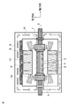
- FIG. 1 is a cross-sectional view showing the overall configuration of the generator according to the first embodiment.
- the rotor 1 has a rotor shaft 2 and a rotor main body 3 provided on the rotor shaft 2.
- the rotor body 3 has a rotor core 4, a plurality of rotor coils (not shown), and a pair of holding rings 5.
- the rotor core 4 is provided with a plurality of rotor slots (not shown).
- the rotor coil is provided in this rotor slot.
- the holding ring 5 surrounds both ends of the rotor core 4 and holds the rotor coil.
- the rotor 1 is converted into an electromagnet by passing a field current through the rotor coil, and is rotated by a prime mover connected to the rotor shaft 2. As a result, power is generated by taking out the output current flowing through the stator coil.
- the rotor shaft 2 is rotatably supported by the frame body 6.
- a pair of blower fans 7 are provided on the rotor shaft 2.
- the blower fans 7 are arranged at both ends of the rotor body 3 in the axial direction so as to face the holding ring 5, and rotate integrally with the rotor shaft 2.
- a stator 8 is installed inside the frame body 6.
- the stator 8 has a cylindrical stator core 9 and a plurality of stator coils 10 provided on the stator core 9.
- the stator 8 is arranged so as to surround the rotor core 4.
- the inner peripheral surface of the stator 8 faces the outer peripheral surface of the rotor 1.
- Cooling gas 11 is sealed in the frame body 6.
- the cooling gas 11 for example, hydrogen or air is used.
- a gas cooler 12 is provided on the radial outer side of the stator 8 in the frame body 6. When the rotor 1 rotates, the blower fan 7 rotates, and the cooling gas 11 circulates in the frame body 6. As a result, each part in the frame body 6 is cooled.
- the cooling gas 11 is sent out by the blower fan 7, passes through the rotor body 3 and the stator 8, and becomes hot. After that, the cooling gas 11 passes through the gas cooler 12, becomes cold, and returns to the blower fan 7.
- FIG. 2A is a cross-sectional view showing the configuration of the rotor end portion of the generator according to the first embodiment
- FIG. 2B is a cross-sectional view taken along the line AA of FIG. 2A
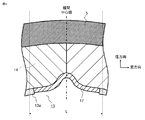
- FIG. 3 is a schematic view showing an enlarged view of FIG. 2 (a).
- a holding ring is shrink-fitted on the rotor shaft 2.
- an end ring 16 is internally fitted at the outer end of the holding ring 5 to prevent deformation of the outer side of the holding ring 5.
- a rotor coil 15, an interpole crossover wire 13, and an insulating block 14 are arranged on the inner diameter side of the holding ring 5.
- An interpole crossover wire 13 is attached to the inner diameter side of the outside of the machine of the holding ring 5 at the end of the rotor.
- the crossover wire 13 has a role of electrically connecting the poles of the rotor.
- the number of poles of the rotor is 2 poles or 4 poles.
- the holding ring 5 and the crossover wire 13 between the poles are insulated by an insulating block 14.
- the rotor shafts 2 of the generator are connected to the prime mover and the exciter at both ends thereof, respectively.
- the interpole crossover wire 13 is provided on the inner diameter side of the holding ring 5 at the rotor end on the exciter side.
- the number of crossovers between poles is one for each generator, and no crossovers between poles are provided on the inner diameter side of the holding ring on the prime mover side.
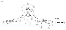
- FIG. 4 is an enlarged cross-sectional view of the rotor end portion of the generator according to the first embodiment as viewed from the axial direction, and is an enlarged view of the portion B surrounded by a broken line, which is a part of FIG. 2B described above.
- the interpole crossing wire 13 has an annular shape, is a region in the interpole center portion 1a of the rotor (a region in the B portion surrounded by the broken line shown in FIG. 2B above, and is the interpole center shown in FIG. A region that is line-symmetric with respect to the line (the range indicated by the length L sandwiched between the two dotted lines in the figure), and a part of the following metal wire is included on both the left and right sides of the interpole center line).
- the interpole crossovers have flexible leads at two locations on the circumference.
- the flexible lead 17 has a structure in which a plurality of copper plates, which are conductive metal plates having a curved shape convex toward the outer diameter side of the rotor, are laminated, and have flexibility. ..
- a tough pitch copper material is used.
- the metal wire 13a is not a laminated structure but a single conductive wire made of the same material.
- the material of the flexible lead is not limited to a copper alloy typified by tough pitch copper or the like, and may be any material having conductivity.
- the shape of the curved portion of the flexible lead 17 is substantially symmetrical with the center line between the poles as the axis of symmetry (this portion is hereinafter referred to as the shape center portion 17a, which will be described in detail later). Further, the layers adjacent to each other in the radial direction of the flexible leads 17 are in contact with each other, and slippage and separation are allowed on the contact surface. Further, both ends of the flexible lead 17 are fixed to the metal wire 13a by brazing or welding. This is to prevent stress from being generated at the manufacturing stage. Further, in the above, although it has been described that there are two flexible leads, it may be one.
- the insulating block 14 is in contact with the outer diameter side of the metal wire 13a of the crossover wire and the flexible lead 17.
- the outer diameter side of the insulating block 14 is covered with an annular holding ring 5 that is shrink-fitted to the rotor end.
- a plurality of insulating blocks 14 are arranged in the circumferential direction. Due to the centrifugal force during rotation, the radius of the ring 5 of the holding ring 5 expands. Along with this, a plurality of insulating blocks 14 arranged in the circumferential direction between the holding ring 5 and the interpole crossover wire 13 move to the outer diameter side. At this time, the radius of the ring of the crossover wire 13 increases along the inner diameter surface of the insulating block 14, but the flexible lead 17 absorbs the elongation of the metal wire 13a in the circumferential direction.
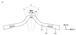
- FIG. 5 is a diagram for explaining a deformed state of the flexible lead.
- both ends of the flexible leads are displaced by ⁇ in the circumferential direction when the rotor is rotated.
- the shape center portion 17a including the convex center line between the poles of each layer of the flexible lead (the region indicated by the angle ⁇ sandwiched between the two two-dot chain lines in the figure.
- each layer The signs of the curvatures of the above are the same.
- the curvature referred to here is a signed curvature. The same applies hereinafter), a bending moment M is generated.
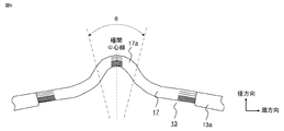
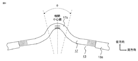
- FIG. 6 is a front view showing an example of the configuration of the flexible lead 17 according to the first embodiment.
- the flexible lead 17 according to the first embodiment when the inner layer side and the outer layer side are divided by half of the total number of laminated layers, the average value of the plate thickness on the inner layer side is smaller than that on the outer layer side.
- the layer on the inner diameter side of the central layer is set as the inner layer side
- the layer on the outer diameter side of the central layer is set as the outer layer side, except for the central layer.
- the thickness of the layers constituting the flexible lead 17 is two or more. Further, the plate thickness of the entire flexible lead is uniform in the circumferential direction. Further, the plate width of the flexible lead 17 in the axial direction is the same as that of the conventional flexible lead, and the conductor cross-sectional area is also the same as that of the conventional one.
- a rotor shaft (not shown) is arranged on the inner diameter side of the interpole crossover wire 13 (composed of the metal wire 13a and the flexible lead 17). A gap is provided between the pole crossover line 13 and the rotor shaft. Similarly, a gap is provided between the shape center of the flexible lead 17 and the rotor shaft. Then, while the rotary electric machine is operating, cooling gas is sent from the outside of the machine to the inside of the machine by a ventilation fan into the gap between the pole crossover line 13 and the rotor shaft.
- the effect of the cooling gas due to ventilation maintains the conventional cooling performance and reduces the maximum stress generated in the flexible lead compared to the conventional one without changing the space given to the flexible lead. , Strength reliability can be improved.
- FIG. 7 is a front view showing an example of the configuration of the flexible lead 17 of the generator according to the second embodiment.
- the thickness of the flexible lead 17 according to the second embodiment gradually decreases from the outer layer side to the inner layer side.
- the number of layers constituting the flexible lead 17 is two or more.
- the type of plate thickness of the layers constituting the flexible lead 17 is the same as the total number of laminated layers.
- the plate thickness of the entire flexible lead is the same in the circumferential direction.
- the other configurations are the same as those in the first embodiment.
- the plate width of the flexible lead 17 in the axial direction is the same as that of the conventional flexible lead, and the conductor cross-sectional area is also the same as that of the conventional one.
- a gap is provided between the pole crossover line 13 and the rotor shaft. Further, a gap is similarly provided between the convex portion of the flexible lead 17 and the rotor shaft.
- cooling gas is sent from the outside of the machine to the inside of the machine by a ventilation fan into the gap between the pole crossover line 13 and the rotor shaft.
- the flexible lead 17 has a structure in which a plurality of copper plates, which are conductive metal plates having a curved shape convex toward the outer diameter side of the rotor, are laminated, and have flexibility.
- a tough pitch copper material is used.
- the metal wire 13a is not a laminated structure but an integral wire.
- the material of the flexible lead 17 is not limited to the copper alloy such as the tough pitch copper, and may be any material having conductivity. The same applies to the material of the metal wire.
- the flexible lead 17 has a curved shape that is convex on the outer diameter side at the center of the shape indicated by the angle ⁇ in the figure, and is substantially symmetrical with the center line between the poles as the axis of symmetry.
- the layers adjacent to each other in the radial direction of the flexible leads 17 are in contact with each other, and slippage and separation are allowed on the contact surface.
- Both ends of the flexible lead 17 are fixed to the metal wire 13a of the crossover wire 13 by brazing or welding. This is to prevent stress from being generated at the manufacturing stage.
- the effect of the cooling gas due to ventilation maintains the conventional cooling performance and reduces the maximum stress generated in the flexible lead compared to the conventional one without changing the space given to the flexible lead. , Strength reliability can be improved.
- FIG. 8 is a front view showing the configuration of the flexible lead 17 of the generator according to the third embodiment.
- the flexible lead 17 according to the third embodiment when the inner layer side and the outer layer side are divided by half of the total number of laminated layers, the area where the average value of the plate thickness on the inner layer side is smaller than that on the outer layer side in the shape center portion 17a is formed. Have. For example, the apex portion including the interpole center line is applicable.
- the layer on the inner diameter side of the central layer is set as the inner layer side
- the layer on the outer diameter side of the central layer is set as the outer layer side, except for the central layer.
- the flexible lead 17 has a substantially symmetrical shape with the center line between the poles as the axis of symmetry.
- the number of layers constituting the flexible lead 17 is two or more.
- the plate thickness of the entire flexible lead is uniform in the circumferential direction.
- Other configurations are the same as those in the first embodiment.
- the plate width of the flexible lead 17 in the axial direction is the same as that of the conventional flexible lead, and the conductor cross-sectional area is also the same as that of the conventional one.
- a gap is provided between the pole crossover line 13 and the rotor shaft (not shown). Further, a gap is similarly provided between the shape center portion 17a of the flexible lead 17 and the rotor shaft.
- cooling gas is sent from the outside of the machine to the inside of the machine by a ventilation fan into the gap between the pole crossover line 13 and the rotor shaft.
- the flexible lead 17 has a structure in which a plurality of copper plates, which are conductive metal plates having a curved shape that is convex on the outer diameter side of the rotor, are laminated to provide flexibility. Have.
- a tough pitch copper material is used.
- a single (thick) wire, a metal wire, and a peripheral portion of the flexible lead are connected to each other, and both of them form an interpole crossover wire 13.
- the structure, configuration, or material of the flexible lead of the third embodiment other than the above is the same as that of the first embodiment or the second embodiment, and thus the description thereof will be omitted here.
- the maximum stress generated in the flexible lead can be maintained without changing the space given to the flexible lead while maintaining the conventional cooling performance. It can be reduced compared to the conventional method and the strength reliability can be improved.
- FIG. 9 is a front view showing the configuration of the flexible lead 17 of the generator according to the fourth embodiment.
- the thickness of the flexible lead 17 according to the fourth embodiment gradually decreases from the outer layer side to the inner layer side at the apex portion of the shape center portion curved in a convex shape. Copper plates of uniform thickness are laminated except for the central part of the shape of the flexible lead 17. Then, the plate thickness of each layer of the flexible lead 17 continuously changes from the convexly curved apex portion toward the end portion of the shape center portion.
- the number of layers constituting the flexible lead 17 is two or more.
- the type of plate thickness at the apex of each layer of the flexible lead 17 is the same as the total number of laminated sheets.
- the plate thickness of the entire flexible lead is uniform in the circumferential direction. Other configurations are the same as those in the first embodiment. Further, the plate width of the flexible lead 17 in the axial direction is the same as that of the conventional flexible lead, and the conductor cross-sectional area is also the same as that of the conventional one.
- a gap is provided between the pole crossover line 13 and the rotor shaft (not shown). Further, a gap is similarly provided between the shape center portion 17a of the flexible lead 17 and the rotor shaft. Then, while the rotary electric machine is in operation, cooling gas is sent from the outside of the machine to the inside of the machine by a ventilation fan into the gap between the pole crossover line 13 and the rotor shaft.
- the layers adjacent to each other in the radial direction of the flexible lead 17 are in contact with each other, and slippage and separation are allowed on the contact surface. Both ends of the flexible lead 17 are fixed to the crossover wire 13 by brazing or welding. This is to prevent stress from being generated at the manufacturing stage.
- the structure or material of the flexible lead 17 other than the above is the same as in the other embodiments.
- the maximum stress generated in the flexible lead can be maintained without changing the space given to the flexible lead while maintaining the conventional cooling performance. It can be reduced compared to the conventional method and the strength reliability can be improved.
- the larger the number of copper plates constituting the flexible lead the larger the surface area where heat transfer occurs with the cooling gas per the cross-sectional area of the conductor through which the current flows, and the flexible lead becomes large. Since the heat generation of the material is reduced, the decrease in the tensile strength and the fatigue strength of the material due to the temperature rise is suppressed, and the strength reliability is improved.
- the layer having the thinnest plate thickness of the flexible lead shown in each of the above embodiments has a plate thickness that does not cause buckling at least by its own weight or centrifugal force.
- a turbine generator has been described as an example of a rotary electric machine, but it can also be applied to other generators and electric motors.
- stator 1 rotor, 1a center between poles, 2 rotor shaft, 3 rotor body, 4 rotor core, 5 holding ring, 6 frame, 7 blower fan, 8 stator, 9 stator core, 10 stator coil , 11 cooling gas, 12 gas cooler, 13 pole crossing wire, 13a metal wire, 14 insulation block, 15 rotor coil, 16 end ring, 17 flexible lead, 17a shape center
Landscapes
- Engineering & Computer Science (AREA)
- Power Engineering (AREA)
- Windings For Motors And Generators (AREA)
- Insulation, Fastening Of Motor, Generator Windings (AREA)
Priority Applications (5)
| Application Number | Priority Date | Filing Date | Title |
|---|---|---|---|
| JP2022502766A JP7270830B2 (ja) | 2020-02-28 | 2020-02-28 | 回転電機 |
| PCT/JP2020/008259 WO2021171544A1 (ja) | 2020-02-28 | 2020-02-28 | 回転電機 |
| CN202080097295.2A CN115176402B (zh) | 2020-02-28 | 2020-02-28 | 旋转电机 |
| US17/781,744 US11742712B2 (en) | 2020-02-28 | 2020-02-28 | Rotary electric machine |
| DE112020006819.6T DE112020006819T5 (de) | 2020-02-28 | 2020-02-28 | Rotierende elektrische maschine |
Applications Claiming Priority (1)
| Application Number | Priority Date | Filing Date | Title |
|---|---|---|---|
| PCT/JP2020/008259 WO2021171544A1 (ja) | 2020-02-28 | 2020-02-28 | 回転電機 |
Publications (1)
| Publication Number | Publication Date |
|---|---|
| WO2021171544A1 true WO2021171544A1 (ja) | 2021-09-02 |
Family
ID=77491265
Family Applications (1)
| Application Number | Title | Priority Date | Filing Date |
|---|---|---|---|
| PCT/JP2020/008259 Ceased WO2021171544A1 (ja) | 2020-02-28 | 2020-02-28 | 回転電機 |
Country Status (5)
| Country | Link |
|---|---|
| US (1) | US11742712B2 (https=) |
| JP (1) | JP7270830B2 (https=) |
| CN (1) | CN115176402B (https=) |
| DE (1) | DE112020006819T5 (https=) |
| WO (1) | WO2021171544A1 (https=) |
Families Citing this family (1)
| Publication number | Priority date | Publication date | Assignee | Title |
|---|---|---|---|---|
| EP4510429A1 (en) * | 2023-08-16 | 2025-02-19 | GE Aviation Systems LLC | Method and apparatus for cooling a rotor assembly |
Citations (3)
| Publication number | Priority date | Publication date | Assignee | Title |
|---|---|---|---|---|
| JPS58182441A (ja) * | 1982-04-19 | 1983-10-25 | Hitachi Ltd | 回転子の界磁巻線装置 |
| JPS6026425A (ja) * | 1983-07-22 | 1985-02-09 | Hitachi Ltd | 回転界磁巻線の極間接続装置 |
| JPS63103636A (ja) * | 1986-10-20 | 1988-05-09 | Toshiba Corp | 回転子のスロツトア−マ |
Family Cites Families (9)
| Publication number | Priority date | Publication date | Assignee | Title |
|---|---|---|---|---|
| JPS55144737A (en) | 1979-04-26 | 1980-11-11 | Hitachi Ltd | Interpole connecting device for field coil |
| JPS62104446A (ja) | 1985-10-30 | 1987-05-14 | Hitachi Ltd | 回転電機の極間接続構造 |
| US4870308A (en) * | 1988-06-17 | 1989-09-26 | Westinghouse Electric Corp. | Flexible conductor and dynamoelectric machine incorporating the same |
| US5111097A (en) * | 1990-11-30 | 1992-05-05 | Westinghouse Electric Corp. | Rotor pole crossover |
| US7247966B2 (en) * | 2004-06-24 | 2007-07-24 | Siemens Power Generation, Inc. | Flexible rotor pole crossover for a generator |
| US6930434B1 (en) * | 2004-11-04 | 2005-08-16 | Siemens Westinghouse Power Corporation | Generator rotor pole crossover |
| EP2608367B1 (en) * | 2010-08-18 | 2020-01-15 | Mitsubishi Electric Corporation | Fixation structure of radial lead of rotating electrical machine |
| JP5554383B2 (ja) * | 2012-09-11 | 2014-07-23 | 三菱電機株式会社 | 回転電機の固定子、及びその固定子の製造方法 |
| JP5662523B2 (ja) * | 2013-06-20 | 2015-01-28 | 株式会社神戸製鋼所 | 発電機 |
-
2020
- 2020-02-28 DE DE112020006819.6T patent/DE112020006819T5/de active Pending
- 2020-02-28 CN CN202080097295.2A patent/CN115176402B/zh active Active
- 2020-02-28 WO PCT/JP2020/008259 patent/WO2021171544A1/ja not_active Ceased
- 2020-02-28 JP JP2022502766A patent/JP7270830B2/ja active Active
- 2020-02-28 US US17/781,744 patent/US11742712B2/en active Active
Patent Citations (3)
| Publication number | Priority date | Publication date | Assignee | Title |
|---|---|---|---|---|
| JPS58182441A (ja) * | 1982-04-19 | 1983-10-25 | Hitachi Ltd | 回転子の界磁巻線装置 |
| JPS6026425A (ja) * | 1983-07-22 | 1985-02-09 | Hitachi Ltd | 回転界磁巻線の極間接続装置 |
| JPS63103636A (ja) * | 1986-10-20 | 1988-05-09 | Toshiba Corp | 回転子のスロツトア−マ |
Also Published As
| Publication number | Publication date |
|---|---|
| US20230014443A1 (en) | 2023-01-19 |
| JP7270830B2 (ja) | 2023-05-10 |
| CN115176402B (zh) | 2025-08-05 |
| CN115176402A (zh) | 2022-10-11 |
| US11742712B2 (en) | 2023-08-29 |
| JPWO2021171544A1 (https=) | 2021-09-02 |
| DE112020006819T5 (de) | 2022-12-15 |
Similar Documents
| Publication | Publication Date | Title |
|---|---|---|
| US7619332B2 (en) | Permanent magnet type electric rotating machine and wind turbine electric power generation system | |
| JP5842856B2 (ja) | 回転電機の固定子 | |
| EP2136455A1 (en) | An electric motor provided with a cooling arrangement | |
| JP5038595B2 (ja) | 積層界磁巻線のホットスポット温度を低下させる方法及び装置 | |
| JP2013188034A (ja) | 回転電機 | |
| JP7046155B2 (ja) | 固定子、電動機、圧縮機および空気調和装置 | |
| JP6469964B2 (ja) | 永久磁石式回転電機 | |
| CN101151781B (zh) | 单相电动机及密闭式压缩机 | |
| JP7270830B2 (ja) | 回転電機 | |
| JP6169496B2 (ja) | 永久磁石式回転電機 | |
| CN112655141B (zh) | 笼型转子及旋转电机 | |
| WO2024204184A1 (ja) | ラジアル磁気軸受、圧縮機、及び冷凍機 | |
| JP2004282858A (ja) | 固定子及びそれを用いた回転機 | |
| WO2023106338A1 (ja) | モータ | |
| JP5129518B2 (ja) | 回転電機 | |
| JP7609922B2 (ja) | 回転電機 | |
| JP2008043026A (ja) | 車両用回転電機 | |
| JP7590918B2 (ja) | 回転電機および突極形回転子 | |
| JP7415188B2 (ja) | 電磁装置、回転電機、スラスト磁気軸受、送風機、圧縮機、冷凍装置、車両 | |
| JP2024131969A (ja) | 超電導回転電機およびそれを構成する超電導コイル | |
| JP2019050698A (ja) | 回転電機 | |
| EP4092885A1 (en) | Cooling at the axial ends of an electric generator | |
| JP2025154123A (ja) | ロータ、回転電機、圧縮機、および、冷凍装置 | |
| WO2026088672A1 (ja) | 回転電機の固定子コアおよび回転電機 | |
| WO2025262944A1 (ja) | 固定子鉄心、回転電機、および固定子の製造方法 |
Legal Events
| Date | Code | Title | Description |
|---|---|---|---|
| 121 | Ep: the epo has been informed by wipo that ep was designated in this application |
Ref document number: 20920861 Country of ref document: EP Kind code of ref document: A1 |
|
| ENP | Entry into the national phase |
Ref document number: 2022502766 Country of ref document: JP Kind code of ref document: A |
|
| 122 | Ep: pct application non-entry in european phase |
Ref document number: 20920861 Country of ref document: EP Kind code of ref document: A1 |
|
| WWG | Wipo information: grant in national office |
Ref document number: 202080097295.2 Country of ref document: CN |