WO2021166823A1 - 薬剤識別装置、及び薬剤識別方法 - Google Patents
薬剤識別装置、及び薬剤識別方法 Download PDFInfo
- Publication number
- WO2021166823A1 WO2021166823A1 PCT/JP2021/005416 JP2021005416W WO2021166823A1 WO 2021166823 A1 WO2021166823 A1 WO 2021166823A1 JP 2021005416 W JP2021005416 W JP 2021005416W WO 2021166823 A1 WO2021166823 A1 WO 2021166823A1
- Authority
- WO
- WIPO (PCT)
- Prior art keywords
- drug
- storage case
- packaging bag
- drug identification
- packaging
- Prior art date
- Legal status (The legal status is an assumption and is not a legal conclusion. Google has not performed a legal analysis and makes no representation as to the accuracy of the status listed.)
- Ceased
Links
Images


Classifications
-
- G—PHYSICS
- G16—INFORMATION AND COMMUNICATION TECHNOLOGY [ICT] SPECIALLY ADAPTED FOR SPECIFIC APPLICATION FIELDS
- G16H—HEALTHCARE INFORMATICS, i.e. INFORMATION AND COMMUNICATION TECHNOLOGY [ICT] SPECIALLY ADAPTED FOR THE HANDLING OR PROCESSING OF MEDICAL OR HEALTHCARE DATA
- G16H40/00—ICT specially adapted for the management or administration of healthcare resources or facilities; ICT specially adapted for the management or operation of medical equipment or devices
- G16H40/20—ICT specially adapted for the management or administration of healthcare resources or facilities; ICT specially adapted for the management or operation of medical equipment or devices for the management or administration of healthcare resources or facilities, e.g. managing hospital staff or surgery rooms
-
- G—PHYSICS
- G16—INFORMATION AND COMMUNICATION TECHNOLOGY [ICT] SPECIALLY ADAPTED FOR SPECIFIC APPLICATION FIELDS
- G16H—HEALTHCARE INFORMATICS, i.e. INFORMATION AND COMMUNICATION TECHNOLOGY [ICT] SPECIALLY ADAPTED FOR THE HANDLING OR PROCESSING OF MEDICAL OR HEALTHCARE DATA
- G16H20/00—ICT specially adapted for therapies or health-improving plans, e.g. for handling prescriptions, for steering therapy or for monitoring patient compliance
- G16H20/10—ICT specially adapted for therapies or health-improving plans, e.g. for handling prescriptions, for steering therapy or for monitoring patient compliance relating to drugs or medications, e.g. for ensuring correct administration to patients
-
- G—PHYSICS
- G06—COMPUTING OR CALCULATING; COUNTING
- G06V—IMAGE OR VIDEO RECOGNITION OR UNDERSTANDING
- G06V10/00—Arrangements for image or video recognition or understanding
- G06V10/10—Image acquisition
-
- G—PHYSICS
- G06—COMPUTING OR CALCULATING; COUNTING
- G06V—IMAGE OR VIDEO RECOGNITION OR UNDERSTANDING
- G06V20/00—Scenes; Scene-specific elements
-
- G—PHYSICS
- G16—INFORMATION AND COMMUNICATION TECHNOLOGY [ICT] SPECIALLY ADAPTED FOR SPECIFIC APPLICATION FIELDS
- G16H—HEALTHCARE INFORMATICS, i.e. INFORMATION AND COMMUNICATION TECHNOLOGY [ICT] SPECIALLY ADAPTED FOR THE HANDLING OR PROCESSING OF MEDICAL OR HEALTHCARE DATA
- G16H40/00—ICT specially adapted for the management or administration of healthcare resources or facilities; ICT specially adapted for the management or operation of medical equipment or devices
- G16H40/60—ICT specially adapted for the management or administration of healthcare resources or facilities; ICT specially adapted for the management or operation of medical equipment or devices for the operation of medical equipment or devices
- G16H40/63—ICT specially adapted for the management or administration of healthcare resources or facilities; ICT specially adapted for the management or operation of medical equipment or devices for the operation of medical equipment or devices for local operation
-
- A—HUMAN NECESSITIES
- A61—MEDICAL OR VETERINARY SCIENCE; HYGIENE
- A61J—CONTAINERS SPECIALLY ADAPTED FOR MEDICAL OR PHARMACEUTICAL PURPOSES; DEVICES OR METHODS SPECIALLY ADAPTED FOR BRINGING PHARMACEUTICAL PRODUCTS INTO PARTICULAR PHYSICAL OR ADMINISTERING FORMS; DEVICES FOR ADMINISTERING FOOD OR MEDICINES ORALLY; BABY COMFORTERS; DEVICES FOR RECEIVING SPITTLE
- A61J1/00—Containers specially adapted for medical or pharmaceutical purposes
- A61J1/03—Containers specially adapted for medical or pharmaceutical purposes for pills or tablets
-
- B—PERFORMING OPERATIONS; TRANSPORTING
- B65—CONVEYING; PACKING; STORING; HANDLING THIN OR FILAMENTARY MATERIAL
- B65B—MACHINES, APPARATUS OR DEVICES FOR, OR METHODS OF, PACKAGING ARTICLES OR MATERIALS; UNPACKING
- B65B9/00—Enclosing successive articles, or quantities of material, e.g. liquids or semiliquids, in flat, folded, or tubular webs of flexible sheet material; Subdividing filled flexible tubes to form packages
- B65B9/06—Enclosing successive articles, or quantities of material, in a longitudinally-folded web, or in a web folded into a tube about the articles or quantities of material placed upon it
- B65B9/08—Enclosing successive articles, or quantities of material, in a longitudinally-folded web, or in a web folded into a tube about the articles or quantities of material placed upon it in a web folded and sealed transversely to form pockets which are subsequently filled and then closed by sealing
-
- G—PHYSICS
- G01—MEASURING; TESTING
- G01N—INVESTIGATING OR ANALYSING MATERIALS BY DETERMINING THEIR CHEMICAL OR PHYSICAL PROPERTIES
- G01N21/00—Investigating or analysing materials by the use of optical means, i.e. using sub-millimetre waves, infrared, visible or ultraviolet light
- G01N21/84—Systems specially adapted for particular applications
- G01N21/88—Investigating the presence of flaws or contamination
- G01N21/95—Investigating the presence of flaws or contamination characterised by the material or shape of the object to be examined
- G01N21/9508—Capsules; Tablets
Definitions
- the present invention relates to a drug identification device and a drug identification method.
- a packaging device is used to store the drug in a packaging bag based on the prescription data.
- the auditing device carries out an audit work to inspect whether the drug is stored in the packing bag discharged from the packing device according to the prescription data.
- the drugs may overlap each other. If there is overlap between drugs, the auditing device may not be able to perform an accurate audit.
- the packaging paper is provided in the vibration space provided between the vibration means and the transfer path by the vibration means provided above on the upstream side of the transfer path. Disclose that the plurality of tablets are properly separated by shaking up and down.
- Patent Document 1 in the vibration space downstream of the vibrating means, the drug is in a state of being closer to the front side in the traveling direction in the sachet. Therefore, since the drugs overlap in the sachet, it is difficult to separate the drugs even if vibration is applied. Further, on the upstream side of the vibrating means, the packaging bag is supplied from the lower side to the upper vibrating means, and on the downstream side of the vibrating means, it is supplied to the transport path from the upper side to the lower side. Therefore, the tension of the packaging bag acts on the drug in the packaging bag, and it is difficult for the drug to move.
- the present invention has been made in view of such circumstances, and an object of the present invention is to provide a drug identification device capable of dispersing the overlap of drugs in a sachet, and a drug identification method.
- the drug identification device of the first aspect has a charging port for loading a packaging bag containing a drug, a transport path for transporting the packaging bag loaded from the loading port, and a drug on the transport path.
- An image sensor that images the image
- a processor that identifies the drug based on the image of the drug imaged by the image sensor
- a storage case that houses the packaging bag placed upstream of the inlet, and vibration that vibrates the storage case. It has a device and. According to the first aspect, the overlap of the drugs in the sachet can be dispersed.
- the vibrating device vibrates the storage case in the horizontal direction.
- the packaging bag can be vibrated in the horizontal direction, and the drug can be dispersed in the packaging bag in the horizontal direction.
- the vibrating device vibrates the storage case in a direction orthogonal to the transport direction of the packaging bag.
- the sachet can be vibrated in the width direction, and the drug can be dispersed in the sachet in the width direction.
- the vibration device includes a motor and a cam attached to the motor.
- the storage case can be easily vibrated.
- the storage case is provided with a horizontal guide path whose position is adjusted at the position of the inlet.
- the horizontal transport path to the inlet can be lengthened, and the drug can be easily dispersed in the transport direction.
- the drug identification device of the sixth aspect is provided with a disperser for spreading the drug in the sachet on the transport path.
- the drug can be dispersed on the transport path.
- the drug identification method of the seventh aspect is a transport step of transporting the packaged bag in which the drug is packaged, which is loaded from the charging port, on the transport path, and an imaging step of imaging the drug on the transport path.
- This is a drug identification method comprising an identification step of identifying a drug based on an image of the image of the drug captured, in which a packaging bag is housed in a storage case arranged upstream of the inlet and the storage case is vibrated. It is provided with a vibrating process.
- the overlap of the drugs in the sachet can be dispersed.
- the storage case is vibrated in the horizontal direction in the vibration step.
- the packaging bag can be vibrated in the horizontal direction, and the drug can be dispersed in the packaging bag in the horizontal direction.
- the storage case in the vibration step, is vibrated in a direction orthogonal to the transport direction of the sachet.
- the sachet can be vibrated in the width direction, and the drug can be dispersed in the sachet in the width direction.
- the storage case is vibrated before the packaging bag is put into the charging port.
- the storage case in the vibration step, is vibrated after the packaging bag is put into the inlet.
- the tenth aspect and the eleventh aspect define a preferable aspect when vibrating the storage case.
- the overlap of drugs in the sachet can be dispersed.
- FIG. 1 is a schematic diagram showing the configuration of the drug audit support system of the embodiment.
- FIG. 2 is a block diagram showing a configuration of a receipt computer.
- FIG. 3 is an enlarged view of a packaging mechanism provided in the packaging machine.
- FIG. 4 is a partially enlarged view of the drug identification device.
- FIG. 5 is a partially enlarged view including a vibrating device.
- FIG. 6 is a schematic configuration diagram of a drug identification device.
- FIG. 7 is a diagram showing a state in which the packaging bag is discharged from the discharge port of the packaging device.
- FIG. 8 is a diagram showing the state of the drug in the sachet before and after the vibration.
- FIG. 9 is a diagram showing a modified example of the storage case.
- Drug prescription work performed in hospitals and pharmacies is roughly divided into prescription data input work, picking work, automatic packaging work, audit work, medication guidance and prescription work.
- the pharmacist gives the patient medication instruction and prescription of the packaged drug after the audit.
- FIG. 1 is a schematic configuration diagram of the drug audit support system.
- the drug audit support system 10 includes a packaging device 100, a drug identification device 300, and a receipt computer 500.
- prescription data input work the pharmacist inputs the prescription data described in the prescription into the receipt computer 500.
- prescription data include patient name, age, drug type or drug name, drug dosage, drug usage, or drug dose.
- the term of a drug type of a drug is synonymous with the type of drug or the type of drug.
- the pharmacist operates the receipt computer 500 to print the prescription data from a printer (not shown) connected to the receipt computer 500.
- the pharmacist picks the medicine corresponding to the prescription data from the medicine rack based on the prescription data described in the printed matter output from the printer.
- the drug include tablets, capsules and the like.
- an automatic picking device that automatically picks the drug based on the prescription data input to the receipt computer may be used.
- “upper” and “lower” indicating the direction mean “upper” and “lower” when the drug audit support system is installed in a normally used state.
- “Vertical” and “horizontal” mean that the vertical (V) direction is “vertical”, and the vertical includes substantially vertical. For example, when the vertical direction is 0 °, the range of ⁇ 20 ° is included. ..
- the horizontal (H) direction means “horizontal”, and horizontal includes substantially horizontal. For example, when the horizontal direction is 0 °, a range of ⁇ 20 ° is included.
- the “vertical posture” and the “horizontal posture” determine “vertical” and “horizontal” based on the lateral direction (or width direction) of the continuous packaging bag.
- "Upstream” and “downstream” are related to the transport direction of the packaging paper or the packaging bag, and the side in the transport direction is “downstream” and the side opposite to the transport direction is “upstream” with respect to a certain standard. Means.
- the receipt computer 500 includes a control device 501 including a processor and the like, a display device 502 composed of a display device, and an input device 504 composed of a keyboard.
- the receipt computer 500 is connected to, for example, the network 20 in the hospital.
- FIG. 2 is a block diagram showing the configuration of the receipt computer 500.
- the control device 501 of the receipt computer 500 includes a processor 506 that performs various controls, a storage device 508 that stores various data, and a communication interface 510 that performs data communication between an external network. ..
- the control device 501 is electrically connected to the display device 502 and the input device 504.
- the control device 501 of the receipt computer 500 is connected to the network 20 in the hospital via the communication interface 510.
- the packaging device 100 has a packaging machine controller 101 connected to the network 20 and a housing 102 controlled by the packaging machine controller 101 to perform packaging work.
- the packaging device 100 includes a plurality of feeders 104 for storing a plurality of drugs.
- the plurality of feeders 104 are arranged vertically and horizontally.
- the plurality of feeders 104 can be arranged on the back side when viewed from the front.
- the feeder 104 can drop the stored drug one tablet at a time.
- the packaging machine controller 101 includes a processor (not shown).
- the processor can select the required feeder 104 based on the prescription data from the receipt computer 500 and drop the stored drug downward from the feeder 104. A packet of medicine is dropped down.
- the feeder 104 can be composed of a cassette for accommodating the drug, a shooter for guiding the drug downward from the cassette, and the like.
- the packaging device 100 includes a hopper 106 under the feeder 104.
- the hopper 106 is a tubular member having a wide opening on the upper side and a narrower opening on the lower side than the upper side.
- the hopper 106 collects the drug 50 that falls from the upper feeder 104 (see FIG. 1) and collects the drug in one place on the lower side.
- a charging pipe 108 is provided below the hopper 106.
- a packaging mechanism 110 is provided under the input pipe 108.
- the medicine 50 collected by the hopper 106 is guided to the packaging mechanism 110 by the input pipe 108.
- the input pipe 108 is a tubular member that penetrates vertically.
- the input pipe 108 may have a circular cross section or an elliptical cross section. Further, the input pipe 108 may have a cylindrical shape or a frustum shape.
- the shape of the input pipe 108 is not particularly limited as long as the medicine 50 can be guided to the packaging mechanism 110.
- the drug 50 is, for example, a tablet, a capsule, or the like.
- the wrapping mechanism 110 includes a supply mechanism 114 for sending out the packaging paper 112, and a heat sealing mechanism 116 for heat-sealing the packaging paper 112.
- the packaging paper 112 is made of a heat-sealing material.
- the packaging paper 112 is a state in which a long sheet is folded in half in the lateral direction and rolled into a roll shape.
- the heat seal mechanism 116 has, for example, a vertically arranged vertical heat head 116A and a horizontally arranged horizontal heat head 116B.
- the heat seal mechanism 116 can form a vertical seal portion 118A and a horizontal seal portion 118B on the packaged paper 112 to be conveyed.
- the supply mechanism 114 is composed of, for example, a shaft that holds the roll-shaped packaging paper 112, a drive motor that rotates the shaft, and the like.
- the packaging machine controller 101 can rotate and drive the drive motor intermittently and continuously.
- the packaging paper 112 is conveyed in a vertical posture in which the folded portion is located on the lower side.
- the vertical sealing portion 118A is formed on the packaging paper 112 by the vertical heating head 116A of the heat sealing mechanism 116.
- a perforation forming machine (not shown) is provided on the vertical heat head 116A of the heat sealing mechanism 116.
- the perforation forming machine includes, for example, a plurality of blades capable of penetrating the packing paper 112.
- the perforation 118C is formed on the vertical seal portion 118A by the perforation forming machine.
- the packing paper 112 is in a half-closed state.
- the half-closed packing paper 112 passes through the input pipe 108.
- One packet of the drug 50 is supplied from the charging tube 108 to the semi-closed packing paper 112.
- the lateral heat head 116B of the heat seal mechanism 116 forms the lateral seal portion 118B.
- the packaging paper 112 is a packaging bag 118 divided into individual packages by a heat-sealing portion (vertical sealing portion 118A and horizontal sealing portion 118B) and perforations 118C. By separating the continuous packaging bag 118 along the perforation 118C, the continuous packaging bag 118 is separated into individual packaging bags 118.
- the packaging mechanism 110 can include a print head 122.
- the print head 122 prints on the packaging paper 112.
- the printed information includes, for example, patient names, drug names, usage, and the like.
- the packaging device 100 discharges a continuous packaging bag 118 from the discharge port 120.
- the outlet 120 is a rectangular opening.
- the discharge port 120 is configured such that its long side is inclined by approximately 45 ° to the right in front view with respect to the vertical direction.
- the packaging bag 118 discharged from the discharge port 120 is stored in the storage case 124 arranged below the discharge port 120.
- the drug identification device 300 has a housing 301.
- the housing 301 includes an input port 302 for inserting the continuous packaging bag 118 and an discharge port 334 for discharging the continuous packaging bag 118.
- the drug identification device 300 according to this aspect can be applied to, for example, drug discrimination and drug audit support.
- a display device 336 is provided on the housing 301.
- Various types of information are displayed on the display device 336.
- the various types of information include, for example, information such as patient prescription information, packaging information, and collation results input from the receipt computer 500 or the packaging machine controller 101.
- the inlet 302 and the outlet 334 are arranged vertically along the vertical direction. In the embodiment, the inlet 302 is located above and the outlet 334 is located below.
- a storage box 400 is arranged downstream of the discharge port 334. The storage box 400 stores the packaging bag 118 discharged from the discharge port 334.
- a storage case 200 for accommodating the pre-audit packaging bag 118, a frame 210 for supporting the storage case 200, and a vibrating device 220 for vibrating the storage case 200 are provided.
- the frame 210 and the vibrating device 220 are separable from the housing 301.
- the storage case 200 may be the storage case 124 used in the packaging device 100, or may be different.
- the frame 210 includes a base 210A composed of four sides provided so as to surround the storage box 400, and two columns 210B extending vertically from the base 210A.
- the frame 210 includes a guide rail 212 and a base plate 214 attached to the guide rail 212.
- FIG. 4 is an enlarged view of the drug identification device 300.
- the upper base 210C is provided with two sides extending in the horizontal direction from the tip side of the two columns 210B and one side connecting the two sides, respectively.
- the upper base 210C has a U-shape on three sides. The two sides extending in the horizontal direction are orthogonal to the transport direction F of the packaging bag 118.
- a guide rail 212 parallel to each side is provided on the two horizontally extending sides of the upper base 210C.
- the base plate 214 is slidably attached to the two guide rails 212.
- An opening is formed in the base plate 214, and the storage case 200 is inserted into the opening.
- a step is formed on the wall surface of the storage case 200. Since the step of the storage case 200 is in contact with the peripheral edge of the base plate 214 that defines the opening, the base plate 214 can support the storage case 200.
- the base plate 214 can move along the guide rail 212 while supporting the storage case 200.
- the movement is in the horizontal direction and in the direction orthogonal to the transport direction of the packaging bag 118.
- the movement can be a reciprocating linear motion.
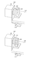
- the vibrating device 220 is composed of a motor 221 and a cam 222 attached to the motor 221.
- the motor 221 is held by the upper base 210C of the frame 210 via the bracket 224.
- the cam 222 rotates.
- the base plate 214 is provided with a U-shaped connecting member 226 extending upward in the vertical direction with respect to the base plate 214.
- the cam 222 is housed in the space of the U-shaped connecting member 226.
- FIG. 5 is a partially enlarged view including the vibrating device 220.
- a cam 222 is attached to the motor 221.
- the cam 222 is eccentric from the axial center of the motor 221.
- the rotation of the cam 222 causes the connecting member 226 to reciprocate.
- the connecting member 226 is connected to the base plate 214, the base plate 214 reciprocates along the guide rail 212.
- the storage case 200 inserted into the base plate 214 reciprocates in synchronization with the movement of the base plate 214.
- a vibrating device 220 composed of a motor 221 and a cam 222 can vibrate the housing case 200 (not shown) via the connecting member 226 and the base plate 214. The vibration can be controlled by the rotation speed of the motor 221 and the size of the cam 222.
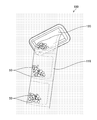
- FIG. 6 is a schematic configuration diagram of the drug identification device 300.
- the drug identification device 300 includes the above-mentioned storage case 200, a frame 210 that supports the storage case 200, and a vibrating device 220 that vibrates the storage case 200, upstream of the inlet 302.
- the housing 301 is provided with a processor 303 that controls the entire drug identification device 300.
- the processor 303 of the drug identification device 300 is connected to the network 20 (see FIG. 1), and prescription information can be obtained from the receipt computer 500 and the packaging machine controller 101.
- a pair of upstream first transport rollers 304 and a pair of downstream second transport rollers 306 are provided downstream of the inlet 302.
- the loading port 302 is oriented so that the packaging bag 118 can be loaded in a lateral posture (horizontal state).
- the first transfer roller 304 and the second transfer roller 306 sandwich the continuous packaging bag 118 from the vertical direction and the horizontal seal portion 118B. By sandwiching the lateral seal portion 118B, it is possible to prevent the drug 50 from being sandwiched between the first transport roller 304 and the second transport roller 306 and being damaged. Note that in FIG. 6, the drug 50 is not shown.
- An imaging region is provided in the transport path between the first transport roller 304 and the second transport roller 306.
- the first camera 308 is arranged on the upper side of the transport path
- the second camera 310 is arranged on the lower side of the transport path.
- the first camera 308 and the second camera 310 are, for example, digital cameras.
- the digital camera includes an image sensor composed of a CCD (Charge Coupled Device), a CMOS (Complementary Metal Oxide Semiconductor), and the like.
- a plurality of light sources 312 are arranged on the upper side and the lower side of the transport path. On the upper side of the transport path, four light sources 312 are arranged at equal intervals on the same circumference around the imaging optical axis of the first camera 308. Similarly, four light sources 312 are arranged at equal intervals on the same circumference around the imaging optical axis of the second camera 310 on the lower side of the transport path.
- the imaging area of the transport path is composed of transparent members.
- the first camera 308 and the second camera 310 take an image of the packaged drug 50 in the packaged bag 118 to be transported from the vertical direction.
- the packaging bag 118 is in a horizontal state.
- the surface surrounded by the vertical seal portion 118A, the horizontal seal portion 118B, and the folded portion of the packaging bag 118 is in a horizontal state. It is preferable to provide a disperser (not shown) in the imaging region.
- the first camera 308 and the second camera 310 image the drug 50 for each packet. From the captured image data, the processor 303 uses the image recognition technology to determine whether or not the agents 50 overlap.
- the processor 303 When it is determined that there is an overlap, the processor 303 operates the disperser to eliminate the overlap of the plurality of drugs 50 in the packaging bag 118. By operating the disperser, the first camera 308 and the second camera 310 can accurately image the drug 50 in the sachet 118.
- a known technique for example, Japanese Patent Application Laid-Open No. 2018-029949
- the disperser In a known technique, for example, in order to image the drug 50 in the imaging region, the transport of the packaging bag 118 is temporarily stopped, and the disperser is moved between the upstream and the downstream along the transport direction until the overlap of the drug 50 is eliminated. Reciprocate.
- the first camera 308 and the second camera 310 image the drug 50 again.
- the disperser is not operated, and the first camera 308 and the second camera 310 do not image the drug 50 again.
- the presence or absence of overlap can be determined as "no overlap" when, for example, the number of drugs 50 having a specific shape is counted and the number matches the number registered in the prescription data.
- the processor 303 uses image recognition technology to extract drug information such as the number, shape, size, color, engraving, and characters of the drug 50 in the sachet 118. ..
- the processor 303 collates the prescription information with the extracted drug information from the receipt computer 500, and displays the collation result on the display device 336. Drug 50 is identified.
- a guide 314 is arranged downstream of the imaging region.
- the guide 314 guides the packing bag 118 to the lower transport path.
- the drug identification device 300 can be provided with a label printer mechanism 316.
- the third camera 330 is arranged at a position facing the label printer mechanism 316 with the transport path in between.
- the third camera 330 takes an image of the perforation 118C formed in the vertical seal portion 118A of the packaging bag 118, and detects the position.
- the label affixing position is adjusted based on the detection position of the perforation 118C.
- the label printer mechanism 316 includes a supply mechanism 320 that sends out a backing sheet 318 with a label, a label printer 322, a label peeling mechanism 324, and a winding mechanism 326 that winds up the backing sheet.
- the supply mechanism 320 is composed of, for example, a shaft that holds a roll-shaped label mount 318, a drive motor that rotates the shaft, and the like.
- the label printer 322 is composed of, for example, a thermal head printer.
- the winding mechanism 326 is composed of a shaft for winding the unlabeled mount 318, a drive motor for rotating the shaft, and the like.
- the print head 122 of the packaging mechanism 110 and the label printer mechanism 316 of the drug identification device 300 can be used in combination, or only one of them can be used.
- a pair of third transport rollers 332 are arranged downstream of the label printer mechanism 316.
- the third transport roller 332 discharges the continuous packaging bag 118 to which the label is attached from the discharge port 334.
- the sachet bag 118 discharged from the discharge port 334 is housed in the storage box 400.
- the storage box 400 is shown, but a winding device may be arranged instead of the storage box 400.
- the take-up device is composed of a take-up shaft, a drive motor for driving the take-up shaft, and the like.
- FIG. 7 shows a state in which the packaging bag 118 is discharged from the discharge port 120 of the packaging device 100.
- the discharge port 120 is tilted by approximately 45 °, when discharged from the packaging device 100, the drug 50 in the packaging bag 118 is one of the packaging bags 118 due to gravity. It is biased to the corner of. A plurality of drugs 50 are overlapped.
- the drug 50 is transported to the drug identification device 300 in a state of being biased to one corner in the packaging bag 118. Even if the disperser is provided in the imaging region of the drug identification device 300, there is a concern that it may take time to disperse the drug 50. When the disperser is operated with the packaging bag 118 stopped, shortening the dispersal time is important for improving the throughput of the drug identification device 300.
- the packaging bag 118 discharged from the discharge port 120 of the packaging device 100 is housed in the storage case 200.
- the tip of the packaging bag 118 is inserted into the drug identification device 300 into the charging port 302.
- the cam 222 is rotated by rotating the motor 221.
- the connecting member 226 reciprocates linearly due to the rotation of the cam 222. Since the connecting member 226 is attached to the base plate 214 that can move along the guide rail 212, the base plate 214 reciprocates in a direction orthogonal to the transport direction, and the storage case 200 supported by the base plate 214 is moved in the transport direction. It vibrates in the orthogonal direction.
- the rotational motion of the cam 222 is converted into a reciprocating linear motion by the connecting member 226, the base plate 214, and the guide rail 212.
- the sachet bag 118 is arranged horizontally in the state where the storage case 200 is housed.
- the storage case 200 is vibrated in the horizontal direction and in the direction orthogonal to the transport direction, and the packaging bag 118 is vibrated in the storage case 200 in the horizontal direction and in the direction orthogonal to the transport direction.
- the drug 50 is in a state of being biased to one corner of the sachet 118.
- the drug 50 is separated in the packaging bag 118 by vibrating the packaged bag 118 contained in the storage case 200 in a direction orthogonal to the transport direction. It can be dispersed in the width direction of the packaging bag 118.
- the storage case 200 contains a continuous packaging bag 118, all the agents 50 in the continuous packaging bag 118 can be dispersed at the same time by vibrating the storage case 200.
- the packaging bag 118 in which the drug 50 is dispersed in the width direction is conveyed into the housing 301 from the charging port 302.
- the storage case 200 may be vibrated before the tip of the packaging bag 118 is inserted into the charging port 302, and then the tip of the packaging bag 118 may be inserted into the charging port 302.
- the storage case 200 may be vibrated while feeding the packaging bag 118 from the charging port 302.
- the storage case 200 can be vibrated periodically or irregularly until the packing bag 118 housed in the storage case 200 is discharged to the storage box 400.
- FIG. 9 shows a modified example of the storage case 200.
- a horizontal guide path 240 is installed on the storage case 200.
- the horizontal guide path 240 includes legs 242.
- the legs 242 are placed on the edge of the opening of the storage case 200.
- the height is adjusted by the legs 242, and the horizontal guide path 240 is adjusted to the position of the input port 302.
- the position of the input port 302 is a position in the height direction, and the input port 302 and the horizontal guide path 240 are located at the same height.
- the same height includes substantially the same height, and the horizontal guide path 240 may be located within a range of about ⁇ 50 mm with respect to the input port 302.
- the packaging bag 118 can be vibrated by the vibrating device 220 in a state where the packaging bag 118 is located on the horizontal guide path 240.
- the drug 50 (not shown) in the packaging bag 118 can be easily dispersed in the transport direction.
- the processor 506 that realizes the receipt computer 500 according to the embodiment, the processor of the packaging machine controller 101, and the processor 303 of the drug identification device 300 can be configured by the following processors.
- Various processors include programmable logic devices (Programmable), which are processors whose circuit configurations can be changed after manufacturing, such as CPUs (Central Processing Units) and FPGAs (Field Programmable Gate Arrays), which are general-purpose processors that execute programs and function.
- a dedicated electric circuit which is a processor having a circuit configuration specially designed for executing a specific process such as Logic Device (PLD) or ASIC (Application Specific Integrated Circuit), is included.
- PLD Logic Device
- ASIC Application Specific Integrated Circuit
- One processor may be composed of one of the above-mentioned various processors, or may be composed of two or more processors of the same type or different types.
- one processor may be composed of a plurality of FPGAs or a combination of a CPU and an FPGA.
- a plurality of processors may be configured by one processor.
- configuring a plurality of processors with one processor first, as represented by a computer such as a client or a server, one processor is configured by a combination of one or more CPUs and software, and this processor is configured. There is a form in which is functioning as a plurality of processing units.
- SoC System On Chip
- various processors are configured by using one or more of the above-mentioned various processors as a hardware structure.
- the hardware structure of these various processors is, more specifically, an electric circuit (circuitry) in which circuit elements such as semiconductor elements are combined.
- the storage case 200 is vibrated in the horizontal direction and the direction orthogonal to the transport direction F is shown, but if the drug 50 in the packaging bag 118 can be dispersed, the storage case 200 can be dispersed in another direction. 200 can be vibrated.
- the storage case 200 can be vibrated in the same direction as the transport direction F, and the drug 50 in the packaging bag 118 can be dispersed in the longitudinal direction of the packaging bag 118.
- Drug audit support system 20 Network 50 Drug 100 packaging device 101 Packaging machine controller 102 Housing 104 Feeder 106 Hopper 108 Input pipe 110 Packaging mechanism 112 Packaging paper 114 Supply mechanism 116 Heat seal mechanism 116A Vertical heat head 116B Horizontal heat head 118 Packaging bag 118A Vertical seal 118B Horizontal seal 118C Perforation 120 Discharge port 122 Print head 124 Storage case 200 Storage case 210 Frame 210A Base 210B Support 210C Upper stand 212 Guide rail 214 Base plate 220 Vibration device 221 Motor 222 Cam 224 Bracket 226 Connecting member 240 Horizontal guide path 242 Leg 300 Drug identification device 301 Housing 302 Input port 303 Processor 304 1st transfer roller 306 2nd transfer roller 308 1st camera 310 2nd camera 312 Light source 314 Guide 316 Label printer mechanism 318 Mount 320 Supply Mechanism 322 Label printer 324 Label peeling mechanism 326 Winding mechanism 330 Third camera 332 Third transport roller 334 Discharge port 336 Display device 400 Storage box 500 Receipt computer
Landscapes
- Engineering & Computer Science (AREA)
- Health & Medical Sciences (AREA)
- Epidemiology (AREA)
- General Health & Medical Sciences (AREA)
- Medical Informatics (AREA)
- Primary Health Care (AREA)
- Public Health (AREA)
- Biomedical Technology (AREA)
- General Business, Economics & Management (AREA)
- Business, Economics & Management (AREA)
- Multimedia (AREA)
- General Physics & Mathematics (AREA)
- Physics & Mathematics (AREA)
- Theoretical Computer Science (AREA)
- Medicinal Chemistry (AREA)
- Bioinformatics & Cheminformatics (AREA)
- Chemical & Material Sciences (AREA)
- Medical Preparation Storing Or Oral Administration Devices (AREA)
Priority Applications (4)
| Application Number | Priority Date | Filing Date | Title |
|---|---|---|---|
| CN202180014310.7A CN115087419A (zh) | 2020-02-21 | 2021-02-15 | 药剂识别装置以及药剂识别方法 |
| JP2022501862A JP7375159B2 (ja) | 2020-02-21 | 2021-02-15 | 薬剤識別装置、及び薬剤識別方法 |
| EP21756888.0A EP4108222A1 (en) | 2020-02-21 | 2021-02-15 | Drug identification device and drug identification method |
| US17/891,282 US20220392600A1 (en) | 2020-02-21 | 2022-08-19 | Drug identification device and drug identification method |
Applications Claiming Priority (2)
| Application Number | Priority Date | Filing Date | Title |
|---|---|---|---|
| JP2020028454 | 2020-02-21 | ||
| JP2020-028454 | 2020-02-21 |
Related Child Applications (1)
| Application Number | Title | Priority Date | Filing Date |
|---|---|---|---|
| US17/891,282 Continuation US20220392600A1 (en) | 2020-02-21 | 2022-08-19 | Drug identification device and drug identification method |
Publications (1)
| Publication Number | Publication Date |
|---|---|
| WO2021166823A1 true WO2021166823A1 (ja) | 2021-08-26 |
Family
ID=77391222
Family Applications (1)
| Application Number | Title | Priority Date | Filing Date |
|---|---|---|---|
| PCT/JP2021/005416 Ceased WO2021166823A1 (ja) | 2020-02-21 | 2021-02-15 | 薬剤識別装置、及び薬剤識別方法 |
Country Status (5)
| Country | Link |
|---|---|
| US (1) | US20220392600A1 (https=) |
| EP (1) | EP4108222A1 (https=) |
| JP (1) | JP7375159B2 (https=) |
| CN (1) | CN115087419A (https=) |
| WO (1) | WO2021166823A1 (https=) |
Families Citing this family (1)
| Publication number | Priority date | Publication date | Assignee | Title |
|---|---|---|---|---|
| TWI909983B (zh) * | 2025-03-10 | 2025-12-21 | 長庚大學 | 藥品辨識方法 |
Citations (7)
| Publication number | Priority date | Publication date | Assignee | Title |
|---|---|---|---|---|
| JPH08322913A (ja) * | 1995-05-30 | 1996-12-10 | Sanyo Electric Co Ltd | 錠剤検査システム |
| JPH11309198A (ja) * | 1999-03-23 | 1999-11-09 | Yuyama Seisakusho:Kk | 薬剤包装機 |
| JP2011036485A (ja) * | 2009-08-12 | 2011-02-24 | Kansai Seiki Kogyo Kk | 分包薬剤検査装置 |
| WO2012081261A1 (ja) * | 2010-12-17 | 2012-06-21 | パナソニック株式会社 | 錠剤鑑査装置 |
| US20150070485A1 (en) * | 2013-09-11 | 2015-03-12 | Jvm Co., Ltd. | Medicine package inspection apparatus |
| WO2018012837A1 (ko) * | 2016-07-11 | 2018-01-18 | (주)크레템 | 약제 포장 불량 감지 유닛, 및 이를 구비한 약제 포장 장치 |
| JP2018029949A (ja) | 2016-08-17 | 2018-03-01 | 富士フイルム株式会社 | 調剤監査装置、及び方法 |
Family Cites Families (4)
| Publication number | Priority date | Publication date | Assignee | Title |
|---|---|---|---|---|
| KR20180122044A (ko) * | 2011-04-28 | 2018-11-09 | 가부시키가이샤 유야마 세이사쿠쇼 | 약제 감사 장치 및 약제 분포 장치 |
| JP2014073328A (ja) * | 2012-10-05 | 2014-04-24 | Kansai Seiki Kogyo Kk | 分包薬剤検査装置 |
| JP6369456B2 (ja) * | 2013-02-20 | 2018-08-08 | 株式会社湯山製作所 | 薬剤鑑査装置、及び薬剤分包システム |
| JP3218090U (ja) * | 2018-07-09 | 2018-09-20 | 富士フイルム株式会社 | ラベルロール及び薬剤認識装置 |
-
2021
- 2021-02-15 WO PCT/JP2021/005416 patent/WO2021166823A1/ja not_active Ceased
- 2021-02-15 JP JP2022501862A patent/JP7375159B2/ja active Active
- 2021-02-15 CN CN202180014310.7A patent/CN115087419A/zh active Pending
- 2021-02-15 EP EP21756888.0A patent/EP4108222A1/en not_active Withdrawn
-
2022
- 2022-08-19 US US17/891,282 patent/US20220392600A1/en not_active Abandoned
Patent Citations (8)
| Publication number | Priority date | Publication date | Assignee | Title |
|---|---|---|---|---|
| JPH08322913A (ja) * | 1995-05-30 | 1996-12-10 | Sanyo Electric Co Ltd | 錠剤検査システム |
| JPH11309198A (ja) * | 1999-03-23 | 1999-11-09 | Yuyama Seisakusho:Kk | 薬剤包装機 |
| JP2011036485A (ja) * | 2009-08-12 | 2011-02-24 | Kansai Seiki Kogyo Kk | 分包薬剤検査装置 |
| WO2012081261A1 (ja) * | 2010-12-17 | 2012-06-21 | パナソニック株式会社 | 錠剤鑑査装置 |
| JP5886209B2 (ja) | 2010-12-17 | 2016-03-16 | パナソニックヘルスケアホールディングス株式会社 | 錠剤鑑査装置 |
| US20150070485A1 (en) * | 2013-09-11 | 2015-03-12 | Jvm Co., Ltd. | Medicine package inspection apparatus |
| WO2018012837A1 (ko) * | 2016-07-11 | 2018-01-18 | (주)크레템 | 약제 포장 불량 감지 유닛, 및 이를 구비한 약제 포장 장치 |
| JP2018029949A (ja) | 2016-08-17 | 2018-03-01 | 富士フイルム株式会社 | 調剤監査装置、及び方法 |
Also Published As
| Publication number | Publication date |
|---|---|
| US20220392600A1 (en) | 2022-12-08 |
| JP7375159B2 (ja) | 2023-11-07 |
| JPWO2021166823A1 (https=) | 2021-08-26 |
| EP4108222A1 (en) | 2022-12-28 |
| CN115087419A (zh) | 2022-09-20 |
Similar Documents
| Publication | Publication Date | Title |
|---|---|---|
| KR100650285B1 (ko) | 약포 검사시스템 | |
| TWI405698B (zh) | 藥品包裝裝置及藥品包裝方法 | |
| CN107499544B (zh) | 药物包装设备 | |
| TWI746577B (zh) | 檢查輔助系統 | |
| JP2023068159A (ja) | 薬剤包装装置 | |
| CN109475469B (zh) | 配药监查装置以及方法 | |
| CN107072881A (zh) | 检查辅助系统、片剂分包装置 | |
| JP7301988B2 (ja) | 搬送機、及び薬剤監査支援システム | |
| CN206984551U (zh) | 控制装置 | |
| KR101576202B1 (ko) | 약제 포장장치 | |
| JP7375159B2 (ja) | 薬剤識別装置、及び薬剤識別方法 | |
| JP7282978B2 (ja) | 薬剤識別装置 | |
| JP6911160B2 (ja) | 薬剤監査支援システム | |
| JP2004238066A (ja) | 錠剤計数監査装置 | |
| JP7413743B2 (ja) | 薬剤一包化パック搬送装置 | |
| JP2015073572A (ja) | コンピュータ、錠剤供給装置、薬剤包装装置およびその制御方法とプログラム。 | |
| JP2023053940A (ja) | 分包薬剤の鑑査装置、鑑査装置の制御プログラム、及び鑑査方法 | |
| KR102286533B1 (ko) | 약포 검사장치 | |
| JP2013039289A (ja) | 分包薬剤監査装置 | |
| JP6367549B2 (ja) | 錠剤供給装置、錠剤供給装置の制御方法、およびプログラム | |
| US12325544B2 (en) | Cover attachment unit for blister pack and blister packing apparatus for drugs, comprising same | |
| JP2004236997A (ja) | 錠剤計数監査装置 | |
| KR20180006812A (ko) | 약제 포장 불량 감지 유닛, 및 이를 구비한 약제 포장 장치 | |
| KR20070018763A (ko) | 일련의 약품을 검사하는 장치 및 방법 | |
| JP2011036485A (ja) | 分包薬剤検査装置 |
Legal Events
| Date | Code | Title | Description |
|---|---|---|---|
| 121 | Ep: the epo has been informed by wipo that ep was designated in this application |
Ref document number: 21756888 Country of ref document: EP Kind code of ref document: A1 |
|
| ENP | Entry into the national phase |
Ref document number: 2022501862 Country of ref document: JP Kind code of ref document: A |
|
| NENP | Non-entry into the national phase |
Ref country code: DE |
|
| ENP | Entry into the national phase |
Ref document number: 2021756888 Country of ref document: EP Effective date: 20220921 |