WO2021166823A1 - Drug identification device and drug identification method - Google Patents
Drug identification device and drug identification method Download PDFInfo
- Publication number
- WO2021166823A1 WO2021166823A1 PCT/JP2021/005416 JP2021005416W WO2021166823A1 WO 2021166823 A1 WO2021166823 A1 WO 2021166823A1 JP 2021005416 W JP2021005416 W JP 2021005416W WO 2021166823 A1 WO2021166823 A1 WO 2021166823A1
- Authority
- WO
- WIPO (PCT)
- Prior art keywords
- drug
- storage case
- packaging bag
- drug identification
- packaging
- Prior art date
Links
Images


Classifications
-
- G—PHYSICS
- G16—INFORMATION AND COMMUNICATION TECHNOLOGY [ICT] SPECIALLY ADAPTED FOR SPECIFIC APPLICATION FIELDS
- G16H—HEALTHCARE INFORMATICS, i.e. INFORMATION AND COMMUNICATION TECHNOLOGY [ICT] SPECIALLY ADAPTED FOR THE HANDLING OR PROCESSING OF MEDICAL OR HEALTHCARE DATA
- G16H40/00—ICT specially adapted for the management or administration of healthcare resources or facilities; ICT specially adapted for the management or operation of medical equipment or devices
- G16H40/20—ICT specially adapted for the management or administration of healthcare resources or facilities; ICT specially adapted for the management or operation of medical equipment or devices for the management or administration of healthcare resources or facilities, e.g. managing hospital staff or surgery rooms
-
- G—PHYSICS
- G16—INFORMATION AND COMMUNICATION TECHNOLOGY [ICT] SPECIALLY ADAPTED FOR SPECIFIC APPLICATION FIELDS
- G16H—HEALTHCARE INFORMATICS, i.e. INFORMATION AND COMMUNICATION TECHNOLOGY [ICT] SPECIALLY ADAPTED FOR THE HANDLING OR PROCESSING OF MEDICAL OR HEALTHCARE DATA
- G16H20/00—ICT specially adapted for therapies or health-improving plans, e.g. for handling prescriptions, for steering therapy or for monitoring patient compliance
- G16H20/10—ICT specially adapted for therapies or health-improving plans, e.g. for handling prescriptions, for steering therapy or for monitoring patient compliance relating to drugs or medications, e.g. for ensuring correct administration to patients
-
- G—PHYSICS
- G06—COMPUTING; CALCULATING OR COUNTING
- G06V—IMAGE OR VIDEO RECOGNITION OR UNDERSTANDING
- G06V10/00—Arrangements for image or video recognition or understanding
- G06V10/10—Image acquisition
-
- G—PHYSICS
- G06—COMPUTING; CALCULATING OR COUNTING
- G06V—IMAGE OR VIDEO RECOGNITION OR UNDERSTANDING
- G06V20/00—Scenes; Scene-specific elements
-
- G—PHYSICS
- G16—INFORMATION AND COMMUNICATION TECHNOLOGY [ICT] SPECIALLY ADAPTED FOR SPECIFIC APPLICATION FIELDS
- G16H—HEALTHCARE INFORMATICS, i.e. INFORMATION AND COMMUNICATION TECHNOLOGY [ICT] SPECIALLY ADAPTED FOR THE HANDLING OR PROCESSING OF MEDICAL OR HEALTHCARE DATA
- G16H40/00—ICT specially adapted for the management or administration of healthcare resources or facilities; ICT specially adapted for the management or operation of medical equipment or devices
- G16H40/60—ICT specially adapted for the management or administration of healthcare resources or facilities; ICT specially adapted for the management or operation of medical equipment or devices for the operation of medical equipment or devices
- G16H40/63—ICT specially adapted for the management or administration of healthcare resources or facilities; ICT specially adapted for the management or operation of medical equipment or devices for the operation of medical equipment or devices for local operation
-
- A—HUMAN NECESSITIES
- A61—MEDICAL OR VETERINARY SCIENCE; HYGIENE
- A61J—CONTAINERS SPECIALLY ADAPTED FOR MEDICAL OR PHARMACEUTICAL PURPOSES; DEVICES OR METHODS SPECIALLY ADAPTED FOR BRINGING PHARMACEUTICAL PRODUCTS INTO PARTICULAR PHYSICAL OR ADMINISTERING FORMS; DEVICES FOR ADMINISTERING FOOD OR MEDICINES ORALLY; BABY COMFORTERS; DEVICES FOR RECEIVING SPITTLE
- A61J1/00—Containers specially adapted for medical or pharmaceutical purposes
- A61J1/03—Containers specially adapted for medical or pharmaceutical purposes for pills or tablets
-
- B—PERFORMING OPERATIONS; TRANSPORTING
- B65—CONVEYING; PACKING; STORING; HANDLING THIN OR FILAMENTARY MATERIAL
- B65B—MACHINES, APPARATUS OR DEVICES FOR, OR METHODS OF, PACKAGING ARTICLES OR MATERIALS; UNPACKING
- B65B9/00—Enclosing successive articles, or quantities of material, e.g. liquids or semiliquids, in flat, folded, or tubular webs of flexible sheet material; Subdividing filled flexible tubes to form packages
- B65B9/06—Enclosing successive articles, or quantities of material, in a longitudinally-folded web, or in a web folded into a tube about the articles or quantities of material placed upon it
- B65B9/08—Enclosing successive articles, or quantities of material, in a longitudinally-folded web, or in a web folded into a tube about the articles or quantities of material placed upon it in a web folded and sealed transversely to form pockets which are subsequently filled and then closed by sealing
-
- G—PHYSICS
- G01—MEASURING; TESTING
- G01N—INVESTIGATING OR ANALYSING MATERIALS BY DETERMINING THEIR CHEMICAL OR PHYSICAL PROPERTIES
- G01N21/00—Investigating or analysing materials by the use of optical means, i.e. using sub-millimetre waves, infrared, visible or ultraviolet light
- G01N21/84—Systems specially adapted for particular applications
- G01N21/88—Investigating the presence of flaws or contamination
- G01N21/95—Investigating the presence of flaws or contamination characterised by the material or shape of the object to be examined
- G01N21/9508—Capsules; Tablets
Definitions
- the present invention relates to a drug identification device and a drug identification method.
- a packaging device is used to store the drug in a packaging bag based on the prescription data.
- the auditing device carries out an audit work to inspect whether the drug is stored in the packing bag discharged from the packing device according to the prescription data.
- the drugs may overlap each other. If there is overlap between drugs, the auditing device may not be able to perform an accurate audit.
- the packaging paper is provided in the vibration space provided between the vibration means and the transfer path by the vibration means provided above on the upstream side of the transfer path. Disclose that the plurality of tablets are properly separated by shaking up and down.
- Patent Document 1 in the vibration space downstream of the vibrating means, the drug is in a state of being closer to the front side in the traveling direction in the sachet. Therefore, since the drugs overlap in the sachet, it is difficult to separate the drugs even if vibration is applied. Further, on the upstream side of the vibrating means, the packaging bag is supplied from the lower side to the upper vibrating means, and on the downstream side of the vibrating means, it is supplied to the transport path from the upper side to the lower side. Therefore, the tension of the packaging bag acts on the drug in the packaging bag, and it is difficult for the drug to move.
- the present invention has been made in view of such circumstances, and an object of the present invention is to provide a drug identification device capable of dispersing the overlap of drugs in a sachet, and a drug identification method.
- the drug identification device of the first aspect has a charging port for loading a packaging bag containing a drug, a transport path for transporting the packaging bag loaded from the loading port, and a drug on the transport path.
- An image sensor that images the image
- a processor that identifies the drug based on the image of the drug imaged by the image sensor
- a storage case that houses the packaging bag placed upstream of the inlet, and vibration that vibrates the storage case. It has a device and. According to the first aspect, the overlap of the drugs in the sachet can be dispersed.
- the vibrating device vibrates the storage case in the horizontal direction.
- the packaging bag can be vibrated in the horizontal direction, and the drug can be dispersed in the packaging bag in the horizontal direction.
- the vibrating device vibrates the storage case in a direction orthogonal to the transport direction of the packaging bag.
- the sachet can be vibrated in the width direction, and the drug can be dispersed in the sachet in the width direction.
- the vibration device includes a motor and a cam attached to the motor.
- the storage case can be easily vibrated.
- the storage case is provided with a horizontal guide path whose position is adjusted at the position of the inlet.
- the horizontal transport path to the inlet can be lengthened, and the drug can be easily dispersed in the transport direction.
- the drug identification device of the sixth aspect is provided with a disperser for spreading the drug in the sachet on the transport path.
- the drug can be dispersed on the transport path.
- the drug identification method of the seventh aspect is a transport step of transporting the packaged bag in which the drug is packaged, which is loaded from the charging port, on the transport path, and an imaging step of imaging the drug on the transport path.
- This is a drug identification method comprising an identification step of identifying a drug based on an image of the image of the drug captured, in which a packaging bag is housed in a storage case arranged upstream of the inlet and the storage case is vibrated. It is provided with a vibrating process.
- the overlap of the drugs in the sachet can be dispersed.
- the storage case is vibrated in the horizontal direction in the vibration step.
- the packaging bag can be vibrated in the horizontal direction, and the drug can be dispersed in the packaging bag in the horizontal direction.
- the storage case in the vibration step, is vibrated in a direction orthogonal to the transport direction of the sachet.
- the sachet can be vibrated in the width direction, and the drug can be dispersed in the sachet in the width direction.
- the storage case is vibrated before the packaging bag is put into the charging port.
- the storage case in the vibration step, is vibrated after the packaging bag is put into the inlet.
- the tenth aspect and the eleventh aspect define a preferable aspect when vibrating the storage case.
- the overlap of drugs in the sachet can be dispersed.
- FIG. 1 is a schematic diagram showing the configuration of the drug audit support system of the embodiment.
- FIG. 2 is a block diagram showing a configuration of a receipt computer.
- FIG. 3 is an enlarged view of a packaging mechanism provided in the packaging machine.
- FIG. 4 is a partially enlarged view of the drug identification device.
- FIG. 5 is a partially enlarged view including a vibrating device.
- FIG. 6 is a schematic configuration diagram of a drug identification device.
- FIG. 7 is a diagram showing a state in which the packaging bag is discharged from the discharge port of the packaging device.
- FIG. 8 is a diagram showing the state of the drug in the sachet before and after the vibration.
- FIG. 9 is a diagram showing a modified example of the storage case.
- Drug prescription work performed in hospitals and pharmacies is roughly divided into prescription data input work, picking work, automatic packaging work, audit work, medication guidance and prescription work.
- the pharmacist gives the patient medication instruction and prescription of the packaged drug after the audit.
- FIG. 1 is a schematic configuration diagram of the drug audit support system.
- the drug audit support system 10 includes a packaging device 100, a drug identification device 300, and a receipt computer 500.
- prescription data input work the pharmacist inputs the prescription data described in the prescription into the receipt computer 500.
- prescription data include patient name, age, drug type or drug name, drug dosage, drug usage, or drug dose.
- the term of a drug type of a drug is synonymous with the type of drug or the type of drug.
- the pharmacist operates the receipt computer 500 to print the prescription data from a printer (not shown) connected to the receipt computer 500.
- the pharmacist picks the medicine corresponding to the prescription data from the medicine rack based on the prescription data described in the printed matter output from the printer.
- the drug include tablets, capsules and the like.
- an automatic picking device that automatically picks the drug based on the prescription data input to the receipt computer may be used.
- “upper” and “lower” indicating the direction mean “upper” and “lower” when the drug audit support system is installed in a normally used state.
- “Vertical” and “horizontal” mean that the vertical (V) direction is “vertical”, and the vertical includes substantially vertical. For example, when the vertical direction is 0 °, the range of ⁇ 20 ° is included. ..
- the horizontal (H) direction means “horizontal”, and horizontal includes substantially horizontal. For example, when the horizontal direction is 0 °, a range of ⁇ 20 ° is included.
- the “vertical posture” and the “horizontal posture” determine “vertical” and “horizontal” based on the lateral direction (or width direction) of the continuous packaging bag.
- "Upstream” and “downstream” are related to the transport direction of the packaging paper or the packaging bag, and the side in the transport direction is “downstream” and the side opposite to the transport direction is “upstream” with respect to a certain standard. Means.
- the receipt computer 500 includes a control device 501 including a processor and the like, a display device 502 composed of a display device, and an input device 504 composed of a keyboard.
- the receipt computer 500 is connected to, for example, the network 20 in the hospital.
- FIG. 2 is a block diagram showing the configuration of the receipt computer 500.
- the control device 501 of the receipt computer 500 includes a processor 506 that performs various controls, a storage device 508 that stores various data, and a communication interface 510 that performs data communication between an external network. ..
- the control device 501 is electrically connected to the display device 502 and the input device 504.
- the control device 501 of the receipt computer 500 is connected to the network 20 in the hospital via the communication interface 510.
- the packaging device 100 has a packaging machine controller 101 connected to the network 20 and a housing 102 controlled by the packaging machine controller 101 to perform packaging work.
- the packaging device 100 includes a plurality of feeders 104 for storing a plurality of drugs.
- the plurality of feeders 104 are arranged vertically and horizontally.
- the plurality of feeders 104 can be arranged on the back side when viewed from the front.
- the feeder 104 can drop the stored drug one tablet at a time.
- the packaging machine controller 101 includes a processor (not shown).
- the processor can select the required feeder 104 based on the prescription data from the receipt computer 500 and drop the stored drug downward from the feeder 104. A packet of medicine is dropped down.
- the feeder 104 can be composed of a cassette for accommodating the drug, a shooter for guiding the drug downward from the cassette, and the like.
- the packaging device 100 includes a hopper 106 under the feeder 104.
- the hopper 106 is a tubular member having a wide opening on the upper side and a narrower opening on the lower side than the upper side.
- the hopper 106 collects the drug 50 that falls from the upper feeder 104 (see FIG. 1) and collects the drug in one place on the lower side.
- a charging pipe 108 is provided below the hopper 106.
- a packaging mechanism 110 is provided under the input pipe 108.
- the medicine 50 collected by the hopper 106 is guided to the packaging mechanism 110 by the input pipe 108.
- the input pipe 108 is a tubular member that penetrates vertically.
- the input pipe 108 may have a circular cross section or an elliptical cross section. Further, the input pipe 108 may have a cylindrical shape or a frustum shape.
- the shape of the input pipe 108 is not particularly limited as long as the medicine 50 can be guided to the packaging mechanism 110.
- the drug 50 is, for example, a tablet, a capsule, or the like.
- the wrapping mechanism 110 includes a supply mechanism 114 for sending out the packaging paper 112, and a heat sealing mechanism 116 for heat-sealing the packaging paper 112.
- the packaging paper 112 is made of a heat-sealing material.
- the packaging paper 112 is a state in which a long sheet is folded in half in the lateral direction and rolled into a roll shape.
- the heat seal mechanism 116 has, for example, a vertically arranged vertical heat head 116A and a horizontally arranged horizontal heat head 116B.
- the heat seal mechanism 116 can form a vertical seal portion 118A and a horizontal seal portion 118B on the packaged paper 112 to be conveyed.
- the supply mechanism 114 is composed of, for example, a shaft that holds the roll-shaped packaging paper 112, a drive motor that rotates the shaft, and the like.
- the packaging machine controller 101 can rotate and drive the drive motor intermittently and continuously.
- the packaging paper 112 is conveyed in a vertical posture in which the folded portion is located on the lower side.
- the vertical sealing portion 118A is formed on the packaging paper 112 by the vertical heating head 116A of the heat sealing mechanism 116.
- a perforation forming machine (not shown) is provided on the vertical heat head 116A of the heat sealing mechanism 116.
- the perforation forming machine includes, for example, a plurality of blades capable of penetrating the packing paper 112.
- the perforation 118C is formed on the vertical seal portion 118A by the perforation forming machine.
- the packing paper 112 is in a half-closed state.
- the half-closed packing paper 112 passes through the input pipe 108.
- One packet of the drug 50 is supplied from the charging tube 108 to the semi-closed packing paper 112.
- the lateral heat head 116B of the heat seal mechanism 116 forms the lateral seal portion 118B.
- the packaging paper 112 is a packaging bag 118 divided into individual packages by a heat-sealing portion (vertical sealing portion 118A and horizontal sealing portion 118B) and perforations 118C. By separating the continuous packaging bag 118 along the perforation 118C, the continuous packaging bag 118 is separated into individual packaging bags 118.
- the packaging mechanism 110 can include a print head 122.
- the print head 122 prints on the packaging paper 112.
- the printed information includes, for example, patient names, drug names, usage, and the like.
- the packaging device 100 discharges a continuous packaging bag 118 from the discharge port 120.
- the outlet 120 is a rectangular opening.
- the discharge port 120 is configured such that its long side is inclined by approximately 45 ° to the right in front view with respect to the vertical direction.
- the packaging bag 118 discharged from the discharge port 120 is stored in the storage case 124 arranged below the discharge port 120.
- the drug identification device 300 has a housing 301.
- the housing 301 includes an input port 302 for inserting the continuous packaging bag 118 and an discharge port 334 for discharging the continuous packaging bag 118.
- the drug identification device 300 according to this aspect can be applied to, for example, drug discrimination and drug audit support.
- a display device 336 is provided on the housing 301.
- Various types of information are displayed on the display device 336.
- the various types of information include, for example, information such as patient prescription information, packaging information, and collation results input from the receipt computer 500 or the packaging machine controller 101.
- the inlet 302 and the outlet 334 are arranged vertically along the vertical direction. In the embodiment, the inlet 302 is located above and the outlet 334 is located below.
- a storage box 400 is arranged downstream of the discharge port 334. The storage box 400 stores the packaging bag 118 discharged from the discharge port 334.
- a storage case 200 for accommodating the pre-audit packaging bag 118, a frame 210 for supporting the storage case 200, and a vibrating device 220 for vibrating the storage case 200 are provided.
- the frame 210 and the vibrating device 220 are separable from the housing 301.
- the storage case 200 may be the storage case 124 used in the packaging device 100, or may be different.
- the frame 210 includes a base 210A composed of four sides provided so as to surround the storage box 400, and two columns 210B extending vertically from the base 210A.
- the frame 210 includes a guide rail 212 and a base plate 214 attached to the guide rail 212.
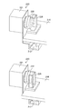
- FIG. 4 is an enlarged view of the drug identification device 300.
- the upper base 210C is provided with two sides extending in the horizontal direction from the tip side of the two columns 210B and one side connecting the two sides, respectively.
- the upper base 210C has a U-shape on three sides. The two sides extending in the horizontal direction are orthogonal to the transport direction F of the packaging bag 118.
- a guide rail 212 parallel to each side is provided on the two horizontally extending sides of the upper base 210C.
- the base plate 214 is slidably attached to the two guide rails 212.
- An opening is formed in the base plate 214, and the storage case 200 is inserted into the opening.
- a step is formed on the wall surface of the storage case 200. Since the step of the storage case 200 is in contact with the peripheral edge of the base plate 214 that defines the opening, the base plate 214 can support the storage case 200.
- the base plate 214 can move along the guide rail 212 while supporting the storage case 200.
- the movement is in the horizontal direction and in the direction orthogonal to the transport direction of the packaging bag 118.
- the movement can be a reciprocating linear motion.
- the vibrating device 220 is composed of a motor 221 and a cam 222 attached to the motor 221.
- the motor 221 is held by the upper base 210C of the frame 210 via the bracket 224.
- the cam 222 rotates.
- the base plate 214 is provided with a U-shaped connecting member 226 extending upward in the vertical direction with respect to the base plate 214.
- the cam 222 is housed in the space of the U-shaped connecting member 226.
- FIG. 5 is a partially enlarged view including the vibrating device 220.
- a cam 222 is attached to the motor 221.
- the cam 222 is eccentric from the axial center of the motor 221.
- the rotation of the cam 222 causes the connecting member 226 to reciprocate.
- the connecting member 226 is connected to the base plate 214, the base plate 214 reciprocates along the guide rail 212.
- the storage case 200 inserted into the base plate 214 reciprocates in synchronization with the movement of the base plate 214.
- a vibrating device 220 composed of a motor 221 and a cam 222 can vibrate the housing case 200 (not shown) via the connecting member 226 and the base plate 214. The vibration can be controlled by the rotation speed of the motor 221 and the size of the cam 222.
- FIG. 6 is a schematic configuration diagram of the drug identification device 300.
- the drug identification device 300 includes the above-mentioned storage case 200, a frame 210 that supports the storage case 200, and a vibrating device 220 that vibrates the storage case 200, upstream of the inlet 302.
- the housing 301 is provided with a processor 303 that controls the entire drug identification device 300.
- the processor 303 of the drug identification device 300 is connected to the network 20 (see FIG. 1), and prescription information can be obtained from the receipt computer 500 and the packaging machine controller 101.
- a pair of upstream first transport rollers 304 and a pair of downstream second transport rollers 306 are provided downstream of the inlet 302.
- the loading port 302 is oriented so that the packaging bag 118 can be loaded in a lateral posture (horizontal state).
- the first transfer roller 304 and the second transfer roller 306 sandwich the continuous packaging bag 118 from the vertical direction and the horizontal seal portion 118B. By sandwiching the lateral seal portion 118B, it is possible to prevent the drug 50 from being sandwiched between the first transport roller 304 and the second transport roller 306 and being damaged. Note that in FIG. 6, the drug 50 is not shown.
- An imaging region is provided in the transport path between the first transport roller 304 and the second transport roller 306.
- the first camera 308 is arranged on the upper side of the transport path
- the second camera 310 is arranged on the lower side of the transport path.
- the first camera 308 and the second camera 310 are, for example, digital cameras.
- the digital camera includes an image sensor composed of a CCD (Charge Coupled Device), a CMOS (Complementary Metal Oxide Semiconductor), and the like.
- a plurality of light sources 312 are arranged on the upper side and the lower side of the transport path. On the upper side of the transport path, four light sources 312 are arranged at equal intervals on the same circumference around the imaging optical axis of the first camera 308. Similarly, four light sources 312 are arranged at equal intervals on the same circumference around the imaging optical axis of the second camera 310 on the lower side of the transport path.
- the imaging area of the transport path is composed of transparent members.
- the first camera 308 and the second camera 310 take an image of the packaged drug 50 in the packaged bag 118 to be transported from the vertical direction.
- the packaging bag 118 is in a horizontal state.
- the surface surrounded by the vertical seal portion 118A, the horizontal seal portion 118B, and the folded portion of the packaging bag 118 is in a horizontal state. It is preferable to provide a disperser (not shown) in the imaging region.
- the first camera 308 and the second camera 310 image the drug 50 for each packet. From the captured image data, the processor 303 uses the image recognition technology to determine whether or not the agents 50 overlap.
- the processor 303 When it is determined that there is an overlap, the processor 303 operates the disperser to eliminate the overlap of the plurality of drugs 50 in the packaging bag 118. By operating the disperser, the first camera 308 and the second camera 310 can accurately image the drug 50 in the sachet 118.
- a known technique for example, Japanese Patent Application Laid-Open No. 2018-029949
- the disperser In a known technique, for example, in order to image the drug 50 in the imaging region, the transport of the packaging bag 118 is temporarily stopped, and the disperser is moved between the upstream and the downstream along the transport direction until the overlap of the drug 50 is eliminated. Reciprocate.
- the first camera 308 and the second camera 310 image the drug 50 again.
- the disperser is not operated, and the first camera 308 and the second camera 310 do not image the drug 50 again.
- the presence or absence of overlap can be determined as "no overlap" when, for example, the number of drugs 50 having a specific shape is counted and the number matches the number registered in the prescription data.
- the processor 303 uses image recognition technology to extract drug information such as the number, shape, size, color, engraving, and characters of the drug 50 in the sachet 118. ..
- the processor 303 collates the prescription information with the extracted drug information from the receipt computer 500, and displays the collation result on the display device 336. Drug 50 is identified.
- a guide 314 is arranged downstream of the imaging region.
- the guide 314 guides the packing bag 118 to the lower transport path.
- the drug identification device 300 can be provided with a label printer mechanism 316.
- the third camera 330 is arranged at a position facing the label printer mechanism 316 with the transport path in between.
- the third camera 330 takes an image of the perforation 118C formed in the vertical seal portion 118A of the packaging bag 118, and detects the position.
- the label affixing position is adjusted based on the detection position of the perforation 118C.
- the label printer mechanism 316 includes a supply mechanism 320 that sends out a backing sheet 318 with a label, a label printer 322, a label peeling mechanism 324, and a winding mechanism 326 that winds up the backing sheet.
- the supply mechanism 320 is composed of, for example, a shaft that holds a roll-shaped label mount 318, a drive motor that rotates the shaft, and the like.
- the label printer 322 is composed of, for example, a thermal head printer.
- the winding mechanism 326 is composed of a shaft for winding the unlabeled mount 318, a drive motor for rotating the shaft, and the like.
- the print head 122 of the packaging mechanism 110 and the label printer mechanism 316 of the drug identification device 300 can be used in combination, or only one of them can be used.
- a pair of third transport rollers 332 are arranged downstream of the label printer mechanism 316.
- the third transport roller 332 discharges the continuous packaging bag 118 to which the label is attached from the discharge port 334.
- the sachet bag 118 discharged from the discharge port 334 is housed in the storage box 400.
- the storage box 400 is shown, but a winding device may be arranged instead of the storage box 400.
- the take-up device is composed of a take-up shaft, a drive motor for driving the take-up shaft, and the like.
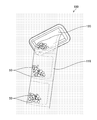
- FIG. 7 shows a state in which the packaging bag 118 is discharged from the discharge port 120 of the packaging device 100.
- the discharge port 120 is tilted by approximately 45 °, when discharged from the packaging device 100, the drug 50 in the packaging bag 118 is one of the packaging bags 118 due to gravity. It is biased to the corner of. A plurality of drugs 50 are overlapped.
- the drug 50 is transported to the drug identification device 300 in a state of being biased to one corner in the packaging bag 118. Even if the disperser is provided in the imaging region of the drug identification device 300, there is a concern that it may take time to disperse the drug 50. When the disperser is operated with the packaging bag 118 stopped, shortening the dispersal time is important for improving the throughput of the drug identification device 300.
- the packaging bag 118 discharged from the discharge port 120 of the packaging device 100 is housed in the storage case 200.
- the tip of the packaging bag 118 is inserted into the drug identification device 300 into the charging port 302.
- the cam 222 is rotated by rotating the motor 221.
- the connecting member 226 reciprocates linearly due to the rotation of the cam 222. Since the connecting member 226 is attached to the base plate 214 that can move along the guide rail 212, the base plate 214 reciprocates in a direction orthogonal to the transport direction, and the storage case 200 supported by the base plate 214 is moved in the transport direction. It vibrates in the orthogonal direction.
- the rotational motion of the cam 222 is converted into a reciprocating linear motion by the connecting member 226, the base plate 214, and the guide rail 212.
- the sachet bag 118 is arranged horizontally in the state where the storage case 200 is housed.
- the storage case 200 is vibrated in the horizontal direction and in the direction orthogonal to the transport direction, and the packaging bag 118 is vibrated in the storage case 200 in the horizontal direction and in the direction orthogonal to the transport direction.
- the drug 50 is in a state of being biased to one corner of the sachet 118.
- the drug 50 is separated in the packaging bag 118 by vibrating the packaged bag 118 contained in the storage case 200 in a direction orthogonal to the transport direction. It can be dispersed in the width direction of the packaging bag 118.
- the storage case 200 contains a continuous packaging bag 118, all the agents 50 in the continuous packaging bag 118 can be dispersed at the same time by vibrating the storage case 200.
- the packaging bag 118 in which the drug 50 is dispersed in the width direction is conveyed into the housing 301 from the charging port 302.
- the storage case 200 may be vibrated before the tip of the packaging bag 118 is inserted into the charging port 302, and then the tip of the packaging bag 118 may be inserted into the charging port 302.
- the storage case 200 may be vibrated while feeding the packaging bag 118 from the charging port 302.
- the storage case 200 can be vibrated periodically or irregularly until the packing bag 118 housed in the storage case 200 is discharged to the storage box 400.
- FIG. 9 shows a modified example of the storage case 200.
- a horizontal guide path 240 is installed on the storage case 200.
- the horizontal guide path 240 includes legs 242.
- the legs 242 are placed on the edge of the opening of the storage case 200.
- the height is adjusted by the legs 242, and the horizontal guide path 240 is adjusted to the position of the input port 302.
- the position of the input port 302 is a position in the height direction, and the input port 302 and the horizontal guide path 240 are located at the same height.
- the same height includes substantially the same height, and the horizontal guide path 240 may be located within a range of about ⁇ 50 mm with respect to the input port 302.
- the packaging bag 118 can be vibrated by the vibrating device 220 in a state where the packaging bag 118 is located on the horizontal guide path 240.
- the drug 50 (not shown) in the packaging bag 118 can be easily dispersed in the transport direction.
- the processor 506 that realizes the receipt computer 500 according to the embodiment, the processor of the packaging machine controller 101, and the processor 303 of the drug identification device 300 can be configured by the following processors.
- Various processors include programmable logic devices (Programmable), which are processors whose circuit configurations can be changed after manufacturing, such as CPUs (Central Processing Units) and FPGAs (Field Programmable Gate Arrays), which are general-purpose processors that execute programs and function.
- a dedicated electric circuit which is a processor having a circuit configuration specially designed for executing a specific process such as Logic Device (PLD) or ASIC (Application Specific Integrated Circuit), is included.
- PLD Logic Device
- ASIC Application Specific Integrated Circuit
- One processor may be composed of one of the above-mentioned various processors, or may be composed of two or more processors of the same type or different types.
- one processor may be composed of a plurality of FPGAs or a combination of a CPU and an FPGA.
- a plurality of processors may be configured by one processor.
- configuring a plurality of processors with one processor first, as represented by a computer such as a client or a server, one processor is configured by a combination of one or more CPUs and software, and this processor is configured. There is a form in which is functioning as a plurality of processing units.
- SoC System On Chip
- various processors are configured by using one or more of the above-mentioned various processors as a hardware structure.
- the hardware structure of these various processors is, more specifically, an electric circuit (circuitry) in which circuit elements such as semiconductor elements are combined.
- the storage case 200 is vibrated in the horizontal direction and the direction orthogonal to the transport direction F is shown, but if the drug 50 in the packaging bag 118 can be dispersed, the storage case 200 can be dispersed in another direction. 200 can be vibrated.
- the storage case 200 can be vibrated in the same direction as the transport direction F, and the drug 50 in the packaging bag 118 can be dispersed in the longitudinal direction of the packaging bag 118.
- Drug audit support system 20 Network 50 Drug 100 packaging device 101 Packaging machine controller 102 Housing 104 Feeder 106 Hopper 108 Input pipe 110 Packaging mechanism 112 Packaging paper 114 Supply mechanism 116 Heat seal mechanism 116A Vertical heat head 116B Horizontal heat head 118 Packaging bag 118A Vertical seal 118B Horizontal seal 118C Perforation 120 Discharge port 122 Print head 124 Storage case 200 Storage case 210 Frame 210A Base 210B Support 210C Upper stand 212 Guide rail 214 Base plate 220 Vibration device 221 Motor 222 Cam 224 Bracket 226 Connecting member 240 Horizontal guide path 242 Leg 300 Drug identification device 301 Housing 302 Input port 303 Processor 304 1st transfer roller 306 2nd transfer roller 308 1st camera 310 2nd camera 312 Light source 314 Guide 316 Label printer mechanism 318 Mount 320 Supply Mechanism 322 Label printer 324 Label peeling mechanism 326 Winding mechanism 330 Third camera 332 Third transport roller 334 Discharge port 336 Display device 400 Storage box 500 Receipt computer
Abstract
Provided are a drug identification device whereby overlap between drugs in a packaging bag can be dispersed, and a drug identification method. A drug identification device having a charging port for charging of a packaging bag in which a drug is packaged, a conveyance path for conveying a packaging bag charged from the charging port, an imaging element for capturing an image of the drug on the conveyance path, a processor for identifying the drug on the basis of the image of the drug captured by the imaging element, an accommodating case for accommodating a packaging bag positioned upstream from the charging port, and a vibration device for causing the accommodating case to vibrate.
Description
本発明は、薬剤識別装置、及び薬剤識別方法に関する。
The present invention relates to a drug identification device and a drug identification method.
近年、病院や薬局等では、分包装置、及び監査装置が導入されている。処方データに基づいて薬剤を分包袋に収納する分包作業が分包装置により実施されている。分包装置から排出された分包袋に処方データの通りに薬剤が収納されているかを検査する監査作業が監査装置により実施されている。
In recent years, packaging devices and auditing devices have been introduced in hospitals and pharmacies. A packaging device is used to store the drug in a packaging bag based on the prescription data. The auditing device carries out an audit work to inspect whether the drug is stored in the packing bag discharged from the packing device according to the prescription data.
分包装置から排出された分包袋では、薬剤同士が重なり合っている場合がある。薬剤同士の重なりがあると、監査装置において監査が正確に実施できない場合がある。このような課題に対応するため、例えば、特許文献1は、搬送路の上流側で、上方に設けられた加振手段により、加振手段と搬送路間に設けた振動空間で分包紙を上下に振ることで、複数の錠剤を適切に分離させることを開示する。
In the packaging bag discharged from the packaging device, the drugs may overlap each other. If there is overlap between drugs, the auditing device may not be able to perform an accurate audit. In order to deal with such a problem, for example, in Patent Document 1, the packaging paper is provided in the vibration space provided between the vibration means and the transfer path by the vibration means provided above on the upstream side of the transfer path. Disclose that the plurality of tablets are properly separated by shaking up and down.
しかしながら、特許文献1では、加振手段の下流の振動空間では、分包袋の中で薬剤が進行方向の前側に寄っている状態である。そのため、分包袋の中で薬剤同士が重なるため、振動を加えても薬剤を分離することは難しい。また、加振手段の上流側では分包袋が下方から上方の加振手段に向けて供給され、加振手段の下流側では上方から下方の搬送路に供給される。そのため、分包袋の中の薬剤に対して分包袋の張力が働き、薬剤が移動し難い。
However, in Patent Document 1, in the vibration space downstream of the vibrating means, the drug is in a state of being closer to the front side in the traveling direction in the sachet. Therefore, since the drugs overlap in the sachet, it is difficult to separate the drugs even if vibration is applied. Further, on the upstream side of the vibrating means, the packaging bag is supplied from the lower side to the upper vibrating means, and on the downstream side of the vibrating means, it is supplied to the transport path from the upper side to the lower side. Therefore, the tension of the packaging bag acts on the drug in the packaging bag, and it is difficult for the drug to move.
本発明は、このような事情に鑑みてなされたもので、分包袋の中の薬剤同士の重なりを分散可能な薬剤識別装置、及び薬剤識別方法を提供することを目的とする。
The present invention has been made in view of such circumstances, and an object of the present invention is to provide a drug identification device capable of dispersing the overlap of drugs in a sachet, and a drug identification method.
第1態様の薬剤識別装置は、薬剤が分包された分包袋を投入するための投入口と、投入口から投入された分包袋を搬送する搬送路と、搬送路の上で、薬剤を撮像する撮像素子と、撮像素子により撮像された薬剤の画像に基づいて薬剤を識別するプロセッサと、投入口の上流に配置された分包袋を収容する収容ケースと、収容ケースを振動させる振動装置と、を有する。第1態様によれば、分包袋の中の薬剤同士の重なりを分散できる。
The drug identification device of the first aspect has a charging port for loading a packaging bag containing a drug, a transport path for transporting the packaging bag loaded from the loading port, and a drug on the transport path. An image sensor that images the image, a processor that identifies the drug based on the image of the drug imaged by the image sensor, a storage case that houses the packaging bag placed upstream of the inlet, and vibration that vibrates the storage case. It has a device and. According to the first aspect, the overlap of the drugs in the sachet can be dispersed.
第2態様の薬剤識別装置において、振動装置は、収容ケースを水平方向に振動する。第2態様によれば、分包袋を水平方向に振動でき、分包袋の中で薬剤を水平方向に分散できる。
In the drug identification device of the second aspect, the vibrating device vibrates the storage case in the horizontal direction. According to the second aspect, the packaging bag can be vibrated in the horizontal direction, and the drug can be dispersed in the packaging bag in the horizontal direction.
第3態様の薬剤識別装置において、振動装置は、収容ケースを分包袋の搬送方向に対し直交する方向に振動する。第3態様によれば、分包袋を幅方向に振動でき、分包袋の中で薬剤を幅方向に分散できる。
In the drug identification device of the third aspect, the vibrating device vibrates the storage case in a direction orthogonal to the transport direction of the packaging bag. According to the third aspect, the sachet can be vibrated in the width direction, and the drug can be dispersed in the sachet in the width direction.
第4態様の薬剤識別装置において、振動装置は、モーターとモーターに取り付けられたカムとを備える。第4態様によれば、収容ケースを容易に振動できる。
In the drug identification device of the fourth aspect, the vibration device includes a motor and a cam attached to the motor. According to the fourth aspect, the storage case can be easily vibrated.
第5態様の薬剤識別装置において、収容ケースは、投入口の位置に位置調整された水平ガイド路を備える。第5態様によれば、投入口までの水平搬送路を長くでき、薬剤を搬送方向に分散しやすくなる。
In the drug identification device of the fifth aspect, the storage case is provided with a horizontal guide path whose position is adjusted at the position of the inlet. According to the fifth aspect, the horizontal transport path to the inlet can be lengthened, and the drug can be easily dispersed in the transport direction.
第6態様の薬剤識別装置において、搬送路の上で、分包袋の中の薬剤を散開する分散装置を備える。第6態様によれば、搬送路の上で、薬剤の分散をできる。
The drug identification device of the sixth aspect is provided with a disperser for spreading the drug in the sachet on the transport path. According to the sixth aspect, the drug can be dispersed on the transport path.
第7態様の薬剤識別方法は、投入口から投入された、薬剤が分包された分包袋を、搬送路の上で搬送する搬送工程と、搬送路の上で、薬剤を撮像する撮像工程と、撮像された薬剤の画像に基づいて薬剤を識別する識別工程と、を備える薬剤識別方法であって、投入口の上流に配置された収容ケースに分包袋を収容し、収容ケースを振動する振動工程を備える。第7態様によれば、分包袋の中の薬剤同士の重なりを分散できる。
The drug identification method of the seventh aspect is a transport step of transporting the packaged bag in which the drug is packaged, which is loaded from the charging port, on the transport path, and an imaging step of imaging the drug on the transport path. This is a drug identification method comprising an identification step of identifying a drug based on an image of the image of the drug captured, in which a packaging bag is housed in a storage case arranged upstream of the inlet and the storage case is vibrated. It is provided with a vibrating process. According to the seventh aspect, the overlap of the drugs in the sachet can be dispersed.
第8態様の薬剤識別方法において、振動工程では、収容ケースを水平方向に振動する。第8態様によれば、分包袋を水平方向に振動でき、分包袋の中で薬剤を水平方向に分散できる。
In the drug identification method of the eighth aspect, the storage case is vibrated in the horizontal direction in the vibration step. According to the eighth aspect, the packaging bag can be vibrated in the horizontal direction, and the drug can be dispersed in the packaging bag in the horizontal direction.
第9態様の薬剤識別方法において、振動工程では、収容ケースを分包袋の搬送方向に対し、直交する方向に振動する。第9態様によれば、分包袋を幅方向に振動でき、分包袋の中で薬剤を幅方向に分散できる。
In the drug identification method of the ninth aspect, in the vibration step, the storage case is vibrated in a direction orthogonal to the transport direction of the sachet. According to the ninth aspect, the sachet can be vibrated in the width direction, and the drug can be dispersed in the sachet in the width direction.
第10態様の薬剤識別方法において、振動工程では、分包袋を投入口に投入する前に収容ケースを振動する。
In the drug identification method of the tenth aspect, in the vibration step, the storage case is vibrated before the packaging bag is put into the charging port.
第11態様の薬剤識別方法において、振動工程では、分包袋を投入口に投入した後に収容ケースを振動する。第10態様、及び第11態様は、収容ケースを振動する際の好ましい態様を規定する。
In the drug identification method of the eleventh aspect, in the vibration step, the storage case is vibrated after the packaging bag is put into the inlet. The tenth aspect and the eleventh aspect define a preferable aspect when vibrating the storage case.
本発明によれば、分包袋の中の薬剤同士の重なりを分散できる。
According to the present invention, the overlap of drugs in the sachet can be dispersed.
以下、添付図面にしたがって本発明の好ましい実施形態について説明する。本発明は以下の好ましい実施形態により説明される。本発明の範囲を逸脱すること無く、多くの手法により変更を行うことができ、本実施形態以外の他の実施形態を利用することができる。したがって、本発明の範囲内における全ての変更が特許請求の範囲に含まれる。
Hereinafter, preferred embodiments of the present invention will be described with reference to the accompanying drawings. The present invention will be described by the following preferred embodiments. Changes can be made by many methods without departing from the scope of the present invention, and other embodiments other than the present embodiment can be used. Therefore, all modifications within the scope of the present invention are included in the claims.
ここで、図中、同一の記号で示される部分は、同様の機能を有する同様の要素である。また、本明細書中で、数値範囲を“ ~ ”を用いて表す場合は、“ ~ ”で示される上限、下限の数値も数値範囲に含むものとする。
Here, in the figure, the parts indicated by the same symbols are similar elements having the same function. Further, in the present specification, when the numerical range is expressed by using "~", the numerical values of the upper limit and the lower limit indicated by "~" are also included in the numerical range.
病院や薬局などで行われる薬剤処方作業は、大別して、処方データ入力作業と、ピッキング作業と、自動分包作業と、監査作業と、服薬指導及び処方作業とを含む。服薬指導及び処方作業では、薬剤師は、監査後に患者に対する服薬指導、並びに分包された薬剤の処方を行う。
Drug prescription work performed in hospitals and pharmacies is roughly divided into prescription data input work, picking work, automatic packaging work, audit work, medication guidance and prescription work. In the medication instruction and prescription work, the pharmacist gives the patient medication instruction and prescription of the packaged drug after the audit.
図1は薬剤監査支援システムの概略構成図である。図1に示されるように、薬剤監査支援システム10は、分包装置100と、薬剤識別装置300と、レセプトコンピュータ500と、を備えている。
FIG. 1 is a schematic configuration diagram of the drug audit support system. As shown in FIG. 1, the drug audit support system 10 includes a packaging device 100, a drug identification device 300, and a receipt computer 500.
処方データ入力作業では、処方箋に記載されている処方データを、薬剤師がレセプトコンピュータ500に入力する。処方データの例として、患者の氏名、年齢、薬剤の薬種、若しくは薬剤の名称、薬剤の分量、薬剤の用法、又は薬剤の用量などが挙げられる。本明細書における、薬剤の薬種の用語は、薬剤の種別、又は薬剤の種類と同義である。
In the prescription data input work, the pharmacist inputs the prescription data described in the prescription into the receipt computer 500. Examples of prescription data include patient name, age, drug type or drug name, drug dosage, drug usage, or drug dose. In the present specification, the term of a drug type of a drug is synonymous with the type of drug or the type of drug.
次いで、薬剤師は、レセプトコンピュータ500を操作して、レセプトコンピュータ500に接続しているプリンタ(不図示)から処方データを印刷する。
Next, the pharmacist operates the receipt computer 500 to print the prescription data from a printer (not shown) connected to the receipt computer 500.
ピッキング作業では、プリンタから出力された印刷物に記載の処方データに基づき、薬剤師が薬剤棚から処方データに対応する薬剤をピッキングする。薬剤の例として、錠剤、及びカプセル剤等が挙げられる。なお、ピッキング作業には、例えば、レセプトコンピュータに入力された処方データに基づき薬剤を自動的にピッキングする自動ピッキング装置を用いてもよい。
In the picking work, the pharmacist picks the medicine corresponding to the prescription data from the medicine rack based on the prescription data described in the printed matter output from the printer. Examples of the drug include tablets, capsules and the like. For the picking operation, for example, an automatic picking device that automatically picks the drug based on the prescription data input to the receipt computer may be used.
本明細書において、方向を表す「上」「下」とは薬剤監査支援システムを通常使用される状態で設置した場合の「上」「下」を意味する。「縦」「横」とは、鉛直(V)の方向が「縦」を意味し、鉛直は略鉛直を含み、例えば、鉛直の方向を0°とした場合、±20°の範囲が含まれる。水平(H)の方向が「横」を意味し、水平は略水平を含み、例えば、水平の方向を0°とした場合、±20°の範囲が含まれる。「縦方向の姿勢」及び「横方向の姿勢」は、連続する分包袋の短手方向(又は幅方向ともいう)を基準に「縦」「横」を判断する。「上流」、及び「下流」とは、分包紙、又は分包袋の搬送方向に関連して、ある基準に対して搬送方向の側が「下流」を、搬送方向と反対の側が「上流」を意味する。
In this specification, "upper" and "lower" indicating the direction mean "upper" and "lower" when the drug audit support system is installed in a normally used state. "Vertical" and "horizontal" mean that the vertical (V) direction is "vertical", and the vertical includes substantially vertical. For example, when the vertical direction is 0 °, the range of ± 20 ° is included. .. The horizontal (H) direction means "horizontal", and horizontal includes substantially horizontal. For example, when the horizontal direction is 0 °, a range of ± 20 ° is included. The "vertical posture" and the "horizontal posture" determine "vertical" and "horizontal" based on the lateral direction (or width direction) of the continuous packaging bag. "Upstream" and "downstream" are related to the transport direction of the packaging paper or the packaging bag, and the side in the transport direction is "downstream" and the side opposite to the transport direction is "upstream" with respect to a certain standard. Means.
<レセプトコンピュータ>
レセプトコンピュータ500は、プロセッサ等を備える制御装置501と、ディスプレイ装置で構成される表示装置502と、キーボードで構成される入力装置504と、を備える。レセプトコンピュータ500は、例えば、病院内のネットワーク20に接続される。 <Receipt computer>
Thereceipt computer 500 includes a control device 501 including a processor and the like, a display device 502 composed of a display device, and an input device 504 composed of a keyboard. The receipt computer 500 is connected to, for example, the network 20 in the hospital.
レセプトコンピュータ500は、プロセッサ等を備える制御装置501と、ディスプレイ装置で構成される表示装置502と、キーボードで構成される入力装置504と、を備える。レセプトコンピュータ500は、例えば、病院内のネットワーク20に接続される。 <Receipt computer>
The
図2は、レセプトコンピュータ500の構成を示すブロック図である。図2に示されるように、レセプトコンピュータ500の制御装置501は、各種制御を行うプロセッサ506と、各種データを記憶する記憶装置508と、外部ネットワークとの間のデータ通信を行う通信インタフェース510を備える。制御装置501は、表示装置502と、入力装置504とに電気的に接続される。レセプトコンピュータ500の制御装置501は通信インタフェース510を介して病院内のネットワーク20に接続される。
FIG. 2 is a block diagram showing the configuration of the receipt computer 500. As shown in FIG. 2, the control device 501 of the receipt computer 500 includes a processor 506 that performs various controls, a storage device 508 that stores various data, and a communication interface 510 that performs data communication between an external network. .. The control device 501 is electrically connected to the display device 502 and the input device 504. The control device 501 of the receipt computer 500 is connected to the network 20 in the hospital via the communication interface 510.
<分包機>
図1に示されるように、分包装置100は、ネットワーク20に接続された分包機コントローラ101と、分包機コントローラ101により制御され分包作業を行う筐体102とを有する。分包装置100は、複数の薬剤を保管するための複数のフィーダ104を備える。複数のフィーダ104は、縦と横に配置される。複数のフィーダ104は正面から見て奥側にも複数のフィーダ104を配置できる。フィーダ104は、保管されている薬剤を下側に一錠ずつ落下できる。 <Packing machine>
As shown in FIG. 1, thepackaging device 100 has a packaging machine controller 101 connected to the network 20 and a housing 102 controlled by the packaging machine controller 101 to perform packaging work. The packaging device 100 includes a plurality of feeders 104 for storing a plurality of drugs. The plurality of feeders 104 are arranged vertically and horizontally. The plurality of feeders 104 can be arranged on the back side when viewed from the front. The feeder 104 can drop the stored drug one tablet at a time.
図1に示されるように、分包装置100は、ネットワーク20に接続された分包機コントローラ101と、分包機コントローラ101により制御され分包作業を行う筐体102とを有する。分包装置100は、複数の薬剤を保管するための複数のフィーダ104を備える。複数のフィーダ104は、縦と横に配置される。複数のフィーダ104は正面から見て奥側にも複数のフィーダ104を配置できる。フィーダ104は、保管されている薬剤を下側に一錠ずつ落下できる。 <Packing machine>
As shown in FIG. 1, the
分包機コントローラ101は不図示のプロセッサを備える。プロセッサは、レセプトコンピュータ500からの処方データに基づいて、必要なフィーダ104を選択し、保管された薬剤をフィーダ104から下側に落下できる。一包分の薬剤が下側に落下される。フィーダ104は、薬剤を収容するカセットと、カセットから薬剤を下側に案内するシュータ等で構成できる。
The packaging machine controller 101 includes a processor (not shown). The processor can select the required feeder 104 based on the prescription data from the receipt computer 500 and drop the stored drug downward from the feeder 104. A packet of medicine is dropped down. The feeder 104 can be composed of a cassette for accommodating the drug, a shooter for guiding the drug downward from the cassette, and the like.
図3に示されるように、分包装置100は、フィーダ104の下側に、ホッパー106を備える。ホッパー106は、上側に広く開口を有し、下側に上側より狭い開口を有する筒状の部材である。ホッパー106は、上側のフィーダ104(図1参照)から落下する薬剤50を収集し、下側で薬剤を一か所に集める。ホッパー106の下側に、投入管108を備える。
As shown in FIG. 3, the packaging device 100 includes a hopper 106 under the feeder 104. The hopper 106 is a tubular member having a wide opening on the upper side and a narrower opening on the lower side than the upper side. The hopper 106 collects the drug 50 that falls from the upper feeder 104 (see FIG. 1) and collects the drug in one place on the lower side. A charging pipe 108 is provided below the hopper 106.
投入管108の下側に、包装機構110を備える。ホッパー106で集められた薬剤50は、投入管108により包装機構110に案内される。投入管108は、上下に貫通する筒形状の部材である。投入管108は、断面が円形状であっても、楕円形状であってもよい。また、投入管108は、円筒形状でも、錐台形状であってもよい。包装機構110に薬剤50を案内できれば、投入管108の形状は特に限定されない。薬剤50は、例えば、錠剤、カプセル剤等である。
A packaging mechanism 110 is provided under the input pipe 108. The medicine 50 collected by the hopper 106 is guided to the packaging mechanism 110 by the input pipe 108. The input pipe 108 is a tubular member that penetrates vertically. The input pipe 108 may have a circular cross section or an elliptical cross section. Further, the input pipe 108 may have a cylindrical shape or a frustum shape. The shape of the input pipe 108 is not particularly limited as long as the medicine 50 can be guided to the packaging mechanism 110. The drug 50 is, for example, a tablet, a capsule, or the like.
包装機構110は、分包紙112を送り出す供給機構114と、分包紙112を熱融着するヒートシール機構116と、を備える。分包紙112は、熱融着性の素材で構成される。分包紙112は、長尺のシートを短手方向に二つ折りにした状態でロール状に巻かれた状態である。
The wrapping mechanism 110 includes a supply mechanism 114 for sending out the packaging paper 112, and a heat sealing mechanism 116 for heat-sealing the packaging paper 112. The packaging paper 112 is made of a heat-sealing material. The packaging paper 112 is a state in which a long sheet is folded in half in the lateral direction and rolled into a roll shape.
ヒートシール機構116は、例えば、縦配置された縦熱ヘッド116Aと横配置された横熱ヘッド116Bとを有する。ヒートシール機構116は搬送される分包紙112に縦シール部118Aと横シール部118Bとを形成できる。
The heat seal mechanism 116 has, for example, a vertically arranged vertical heat head 116A and a horizontally arranged horizontal heat head 116B. The heat seal mechanism 116 can form a vertical seal portion 118A and a horizontal seal portion 118B on the packaged paper 112 to be conveyed.
供給機構114は、例えば、ロール状の分包紙112を保持する軸と、軸を回転する駆動モーター等により構成される。分包機コントローラ101は駆動モーターを間欠的に、又連続的に回転駆動できる。
The supply mechanism 114 is composed of, for example, a shaft that holds the roll-shaped packaging paper 112, a drive motor that rotates the shaft, and the like. The packaging machine controller 101 can rotate and drive the drive motor intermittently and continuously.
分包紙112は、二つ折りの部分を下側に位置された縦方向の姿勢で搬送される。例えば、ヒートシール機構116の縦熱ヘッド116Aにより縦シール部118Aが分包紙112に形成される。ヒートシール機構116の縦熱ヘッド116Aに、ミシン目形成機(不図示)が設けられている。ミシン目形成機は、例えば、分包紙112を貫通できる複数の刃等を備える。縦熱ヘッド116Aが分包紙112を両側から熱融着する際、ミシン目形成機により縦シール部118Aにミシン目118Cが形成される。分包紙112は半閉じの状態になる。
The packaging paper 112 is conveyed in a vertical posture in which the folded portion is located on the lower side. For example, the vertical sealing portion 118A is formed on the packaging paper 112 by the vertical heating head 116A of the heat sealing mechanism 116. A perforation forming machine (not shown) is provided on the vertical heat head 116A of the heat sealing mechanism 116. The perforation forming machine includes, for example, a plurality of blades capable of penetrating the packing paper 112. When the vertical heat head 116A heat-seals the packing paper 112 from both sides, the perforation 118C is formed on the vertical seal portion 118A by the perforation forming machine. The packing paper 112 is in a half-closed state.
次いで、半閉じの分包紙112が投入管108を通過する。一包分の薬剤50が、投入管108から半閉じの分包紙112に供給される。次いで、ヒートシール機構116の横熱ヘッド116Bにより横シール部118Bが形成される。
Next, the half-closed packing paper 112 passes through the input pipe 108. One packet of the drug 50 is supplied from the charging tube 108 to the semi-closed packing paper 112. Next, the lateral heat head 116B of the heat seal mechanism 116 forms the lateral seal portion 118B.
分包紙112が、ヒートシール部(縦シール部118Aと横シール部118B)とミシン目118Cにより、1包ごとに区分けされた分包袋118とされる。なお、ミシン目118Cに沿って連続する分包袋118を切り離すことにより、連続する分包袋118は個別の分包袋118に分離される。
The packaging paper 112 is a packaging bag 118 divided into individual packages by a heat-sealing portion (vertical sealing portion 118A and horizontal sealing portion 118B) and perforations 118C. By separating the continuous packaging bag 118 along the perforation 118C, the continuous packaging bag 118 is separated into individual packaging bags 118.
包装機構110は、プリントヘッド122を備えることができる。プリントヘッド122は、分包紙112に印字を行う。印字される情報は、例えば、患者名、薬剤の名称、及び用法などを含む。
The packaging mechanism 110 can include a print head 122. The print head 122 prints on the packaging paper 112. The printed information includes, for example, patient names, drug names, usage, and the like.
図1に示されるように、分包装置100は、排出口120から、連続する分包袋118を排出する。排出口120は長方形の開口である。排出口120は、その長辺が鉛直方向に対して、正面視で右側に略45°傾斜するよう構成されている。排出口120から排出された分包袋118は、排出口120の下方に配置された収容ケース124に蓄えられる。
As shown in FIG. 1, the packaging device 100 discharges a continuous packaging bag 118 from the discharge port 120. The outlet 120 is a rectangular opening. The discharge port 120 is configured such that its long side is inclined by approximately 45 ° to the right in front view with respect to the vertical direction. The packaging bag 118 discharged from the discharge port 120 is stored in the storage case 124 arranged below the discharge port 120.
<薬剤識別装置>
図1に示されるように、薬剤識別装置300は、筐体301を有する。筐体301は、連続する分包袋118を投入するための投入口302と、連続する分包袋118を排出する排出口334を備える。本態様に係る薬剤識別装置300は、例えば薬剤鑑別、薬剤監査支援に適用することができる。 <Drug identification device>
As shown in FIG. 1, thedrug identification device 300 has a housing 301. The housing 301 includes an input port 302 for inserting the continuous packaging bag 118 and an discharge port 334 for discharging the continuous packaging bag 118. The drug identification device 300 according to this aspect can be applied to, for example, drug discrimination and drug audit support.
図1に示されるように、薬剤識別装置300は、筐体301を有する。筐体301は、連続する分包袋118を投入するための投入口302と、連続する分包袋118を排出する排出口334を備える。本態様に係る薬剤識別装置300は、例えば薬剤鑑別、薬剤監査支援に適用することができる。 <Drug identification device>
As shown in FIG. 1, the
筐体301の上には、表示装置336を備える。表示装置336には、各種の情報が表示される。各種の情報には、例えば、レセプトコンピュータ500又は分包機コントローラ101から入力された患者の処方情報、分包情報、照合結果等の情報等が含まれる。
A display device 336 is provided on the housing 301. Various types of information are displayed on the display device 336. The various types of information include, for example, information such as patient prescription information, packaging information, and collation results input from the receipt computer 500 or the packaging machine controller 101.
投入口302と排出口334とは、鉛直方向に沿って、上下に配置されている。実施形態では、投入口302が上方で、排出口334が下方に配置される。排出口334の下流に、収容ボックス400が配置されている。収容ボックス400は、排出口334から排出された分包袋118を収容する。
The inlet 302 and the outlet 334 are arranged vertically along the vertical direction. In the embodiment, the inlet 302 is located above and the outlet 334 is located below. A storage box 400 is arranged downstream of the discharge port 334. The storage box 400 stores the packaging bag 118 discharged from the discharge port 334.
投入口302の上流に、監査前の分包袋118を収容する収容ケース200と、収容ケース200を支持するフレーム210と、収容ケース200を振動する振動装置220と、を備える。フレーム210及び振動装置220は、筐体301に対して分離可能である。収容ケース200は、分包装置100で使用した収容ケース124であってもよく、また、別であってもよい。
Upstream of the input port 302, a storage case 200 for accommodating the pre-audit packaging bag 118, a frame 210 for supporting the storage case 200, and a vibrating device 220 for vibrating the storage case 200 are provided. The frame 210 and the vibrating device 220 are separable from the housing 301. The storage case 200 may be the storage case 124 used in the packaging device 100, or may be different.
フレーム210は、収容ボックス400を囲うように設けられた4辺で構成される基台210Aと、基台210Aから鉛直方向に延びる2本の支柱210Bと、を備える。フレーム210には、ガイドレール212と、ガイドレール212に取り付けられたベースプレート214とが備えられている。
The frame 210 includes a base 210A composed of four sides provided so as to surround the storage box 400, and two columns 210B extending vertically from the base 210A. The frame 210 includes a guide rail 212 and a base plate 214 attached to the guide rail 212.
図4は、薬剤識別装置300の拡大図である。図4に示されるように、2本の支柱210Bの先端の側からそれぞれ、水平方向に延びる2辺と、2辺を連結する1辺と、から構成される上台210Cを備える。上台210Cは3辺でU字型形状を有している。水平方向に延びる2辺は、分包袋118の搬送方向Fに対して、直交する。
FIG. 4 is an enlarged view of the drug identification device 300. As shown in FIG. 4, the upper base 210C is provided with two sides extending in the horizontal direction from the tip side of the two columns 210B and one side connecting the two sides, respectively. The upper base 210C has a U-shape on three sides. The two sides extending in the horizontal direction are orthogonal to the transport direction F of the packaging bag 118.
上台210Cの水平方向に延びる2辺の上には、それぞれの辺に平行であるガイドレール212が設けられている。ベースプレート214が2本のガイドレール212にスライド可能に取り付けられている。
A guide rail 212 parallel to each side is provided on the two horizontally extending sides of the upper base 210C. The base plate 214 is slidably attached to the two guide rails 212.
ベースプレート214には、開口が形成され、収容ケース200が開口に挿入される。収容ケース200の壁面には段差が形成されている。収容ケース200の段差と、開口を画定するベースプレート214の周縁とが接するので、ベースプレート214は収容ケース200を支持できる。
An opening is formed in the base plate 214, and the storage case 200 is inserted into the opening. A step is formed on the wall surface of the storage case 200. Since the step of the storage case 200 is in contact with the peripheral edge of the base plate 214 that defines the opening, the base plate 214 can support the storage case 200.
ベースプレート214は収容ケース200を支持した状態で、ガイドレール212に沿って移動できる。移動は、水平方向であり、かつ分包袋118の搬送方向に対し直交する方向である。また、移動は往復直線運動できる。
The base plate 214 can move along the guide rail 212 while supporting the storage case 200. The movement is in the horizontal direction and in the direction orthogonal to the transport direction of the packaging bag 118. In addition, the movement can be a reciprocating linear motion.
振動装置220はモーター221と、モーター221に取り付けられたカム222により構成される。モーター221が、ブラケット224を介して、フレーム210の上台210Cに保持されている。モーター221が回転するとカム222が回転する。
The vibrating device 220 is composed of a motor 221 and a cam 222 attached to the motor 221. The motor 221 is held by the upper base 210C of the frame 210 via the bracket 224. When the motor 221 rotates, the cam 222 rotates.
ベースプレート214には、ベースプレート214に対して鉛直方向の上方に延びるU字型の連結部材226が設けられている。カム222が、U字型の連結部材226の空間に収容されている。
The base plate 214 is provided with a U-shaped connecting member 226 extending upward in the vertical direction with respect to the base plate 214. The cam 222 is housed in the space of the U-shaped connecting member 226.
図5は振動装置220を含む部分拡大図である。図5に示されるように、モーター221には、カム222が取り付けられている。カム222は、モーター221の軸心から偏心されている。モーター221が回転するとカム222が回転する。カム222の回転により、連結部材226が往復運動する。連結部材226がベースプレート214に連結されているので、ベースプレート214がガイドレール212に沿って往復運動する。ベースプレート214に挿入された収容ケース200が、ベースプレート214の動きと同期して往復運動する。モーター221とカム222により構成される振動装置220が、連結部材226とベースプレート214とを介して収容ケース200(不図示)を振動できる。振動は、モーター221の回転数、カム222の大きさ等により制御できる。
FIG. 5 is a partially enlarged view including the vibrating device 220. As shown in FIG. 5, a cam 222 is attached to the motor 221. The cam 222 is eccentric from the axial center of the motor 221. When the motor 221 rotates, the cam 222 rotates. The rotation of the cam 222 causes the connecting member 226 to reciprocate. Since the connecting member 226 is connected to the base plate 214, the base plate 214 reciprocates along the guide rail 212. The storage case 200 inserted into the base plate 214 reciprocates in synchronization with the movement of the base plate 214. A vibrating device 220 composed of a motor 221 and a cam 222 can vibrate the housing case 200 (not shown) via the connecting member 226 and the base plate 214. The vibration can be controlled by the rotation speed of the motor 221 and the size of the cam 222.
図6は薬剤識別装置300の概略構成図である。図6に示されるように、薬剤識別装置300は、投入口302の上流に上述した、収容ケース200と、収容ケース200を支持するフレーム210と、収容ケース200を振動する振動装置220を備える。
FIG. 6 is a schematic configuration diagram of the drug identification device 300. As shown in FIG. 6, the drug identification device 300 includes the above-mentioned storage case 200, a frame 210 that supports the storage case 200, and a vibrating device 220 that vibrates the storage case 200, upstream of the inlet 302.
筐体301には薬剤識別装置300の全体を制御するプロセッサ303が備えられている。薬剤識別装置300のプロセッサ303は、ネットワーク20(図1参照)に接続され、レセプトコンピュータ500、及び分包機コントローラ101から処方情報を得ることができる。
The housing 301 is provided with a processor 303 that controls the entire drug identification device 300. The processor 303 of the drug identification device 300 is connected to the network 20 (see FIG. 1), and prescription information can be obtained from the receipt computer 500 and the packaging machine controller 101.
筐体301の内部であって、投入口302の下流に、上流の一対の第1搬送ローラ304と、下流の一対の第2搬送ローラ306とを備える。投入口302は、分包袋118を横方向の姿勢(水平状態)で投入できる向きとされる。第1搬送ローラ304、及び第2搬送ローラ306は、連続する分包袋118を上下方向から、かつ横シール部118Bを挟持する。横シール部118Bを挟持することにより、薬剤50が第1搬送ローラ304及び第2搬送ローラ306に挟み込まれて損傷を受けることを回避できる。なお、図6において、薬剤50は図示されていない。
Inside the housing 301, a pair of upstream first transport rollers 304 and a pair of downstream second transport rollers 306 are provided downstream of the inlet 302. The loading port 302 is oriented so that the packaging bag 118 can be loaded in a lateral posture (horizontal state). The first transfer roller 304 and the second transfer roller 306 sandwich the continuous packaging bag 118 from the vertical direction and the horizontal seal portion 118B. By sandwiching the lateral seal portion 118B, it is possible to prevent the drug 50 from being sandwiched between the first transport roller 304 and the second transport roller 306 and being damaged. Note that in FIG. 6, the drug 50 is not shown.
第1搬送ローラ304と第2搬送ローラ306との間の搬送路に撮像領域が設けられる。撮像領域では、搬送路の上側に第1カメラ308が配置され、搬送路の下側に第2カメラ310が配置される。第1カメラ308及び第2カメラ310は、例えば、デジタルカメラである。デジタルカメラは、CCD(Charge Coupled Device)、CMOS(Complementary Metal Oxide Semiconductor)等により構成される撮像素子を含む。
An imaging region is provided in the transport path between the first transport roller 304 and the second transport roller 306. In the imaging region, the first camera 308 is arranged on the upper side of the transport path, and the second camera 310 is arranged on the lower side of the transport path. The first camera 308 and the second camera 310 are, for example, digital cameras. The digital camera includes an image sensor composed of a CCD (Charge Coupled Device), a CMOS (Complementary Metal Oxide Semiconductor), and the like.
複数の光源312が、搬送路の上側と下側とに配置される。搬送路の上側には4つの光源312が、第1カメラ308の撮像光軸を中心に同一円周上に、等間隔に配置される。同様に、搬送路の下側には4つの光源312が、第2カメラ310の撮像光軸を中心に同一円周上に、等間隔に配置される。
A plurality of light sources 312 are arranged on the upper side and the lower side of the transport path. On the upper side of the transport path, four light sources 312 are arranged at equal intervals on the same circumference around the imaging optical axis of the first camera 308. Similarly, four light sources 312 are arranged at equal intervals on the same circumference around the imaging optical axis of the second camera 310 on the lower side of the transport path.
搬送路の撮像領域は、透明部材で構成される。第1カメラ308と第2カメラ310とは、搬送される分包袋118の分包されている薬剤50を、上下方向から撮像する。撮像領域では、分包袋118は、水平状態になる。分包袋118の縦シール部118A、横シール部118B、及び二つ折り部分で囲まれた面が水平状態とされる。撮像領域には、不図示の分散装置を設けることが好ましい。
The imaging area of the transport path is composed of transparent members. The first camera 308 and the second camera 310 take an image of the packaged drug 50 in the packaged bag 118 to be transported from the vertical direction. In the imaging region, the packaging bag 118 is in a horizontal state. The surface surrounded by the vertical seal portion 118A, the horizontal seal portion 118B, and the folded portion of the packaging bag 118 is in a horizontal state. It is preferable to provide a disperser (not shown) in the imaging region.
第1カメラ308及び第2カメラ310が一包ごとに薬剤50を撮像する。撮像された画像データから、プロセッサ303が画像認識技術を利用することにより、薬剤50の重なりの有無を判断する。
The first camera 308 and the second camera 310 image the drug 50 for each packet. From the captured image data, the processor 303 uses the image recognition technology to determine whether or not the agents 50 overlap.
「重なり有り」と判断されると、プロセッサ303が分散装置を動作させ、分包袋118の中で複数の薬剤50の重なりを解消する。分散装置を動作させることにより、第1カメラ308及び第2カメラ310は、分包袋118の中の薬剤50を正確に撮像できる。分散装置は、公知の技術(例えば、特開2018-029949号等)を適用できる。公知の技術では、例えば、撮像領域で薬剤50を撮像するため分包袋118の搬送が一旦停止され、分散装置を搬送方向に沿って上流と下流の間を、薬剤50の重なりが解消するまで往復運動させる。第1カメラ308及び第2カメラ310が、再度薬剤50を撮像する。一方、「重なり無し」と判断されると、分散装置を動作させず、第1カメラ308及び第2カメラ310は薬剤50を再度撮像しない。
When it is determined that there is an overlap, the processor 303 operates the disperser to eliminate the overlap of the plurality of drugs 50 in the packaging bag 118. By operating the disperser, the first camera 308 and the second camera 310 can accurately image the drug 50 in the sachet 118. A known technique (for example, Japanese Patent Application Laid-Open No. 2018-029949) can be applied to the disperser. In a known technique, for example, in order to image the drug 50 in the imaging region, the transport of the packaging bag 118 is temporarily stopped, and the disperser is moved between the upstream and the downstream along the transport direction until the overlap of the drug 50 is eliminated. Reciprocate. The first camera 308 and the second camera 310 image the drug 50 again. On the other hand, if it is determined that there is no overlap, the disperser is not operated, and the first camera 308 and the second camera 310 do not image the drug 50 again.
重なりの有無は、例えば、特定形状の薬剤50の数をカウントし、その数が処方データに登録されている数と一致した場合に、「重なり無し」と判断できる。
The presence or absence of overlap can be determined as "no overlap" when, for example, the number of drugs 50 having a specific shape is counted and the number matches the number registered in the prescription data.
次に、撮像された画像データから、プロセッサ303が画像認識技術を利用し、分包袋118の中の薬剤50の個数、形状、大きさ、色、刻印、及び文字等の薬剤情報を抽出する。プロセッサ303が、レセプトコンピュータ500から処方情報と、抽出された薬剤情報とを照合し、照合結果を表示装置336に表示する。薬剤50が識別される。
Next, from the captured image data, the processor 303 uses image recognition technology to extract drug information such as the number, shape, size, color, engraving, and characters of the drug 50 in the sachet 118. .. The processor 303 collates the prescription information with the extracted drug information from the receipt computer 500, and displays the collation result on the display device 336. Drug 50 is identified.
撮像領域の下流にはガイド314が配置される。ガイド314は分包袋118を下側の搬送路に案内する。
A guide 314 is arranged downstream of the imaging region. The guide 314 guides the packing bag 118 to the lower transport path.
薬剤識別装置300は、ラベルプリンター機構316を備えることができる。搬送路を挟んでラベルプリンター機構316に対向する位置に第3カメラ330が配置される。第3カメラ330は、分包袋118の縦シール部118Aに形成されたミシン目118Cを撮像し、位置を検出する。ミシン目118Cの検出位置を基準に、ラベルを貼り付け位置が調整される。
The drug identification device 300 can be provided with a label printer mechanism 316. The third camera 330 is arranged at a position facing the label printer mechanism 316 with the transport path in between. The third camera 330 takes an image of the perforation 118C formed in the vertical seal portion 118A of the packaging bag 118, and detects the position. The label affixing position is adjusted based on the detection position of the perforation 118C.
ラベルプリンター機構316は、ラベル付きの台紙318を送り出す供給機構320と、ラベルプリンター322と、ラベル剥離機構324と、台紙を巻き取る巻取機構326とを備える。供給機構320は、例えば、ロール状のラベル付きの台紙318を保持する軸と、軸を回転する駆動モーター等により構成される。ラベルプリンター322は、例えば、サーマルヘッドプリンターで構成される。巻取機構326は、ラベルなしの台紙318を巻き取る軸と、軸を回転する駆動モーター等により構成される。ラベル付きの台紙318を折り曲げることにより、印字済のラベル先端が台紙から剥離される。剥離された印字済のラベルを一対のベルト搬送機構の間を通過させることにより、印字済のラベルが分包袋118に向けて搬送される。印字済のラベルが分包袋118に貼り付けられる。
The label printer mechanism 316 includes a supply mechanism 320 that sends out a backing sheet 318 with a label, a label printer 322, a label peeling mechanism 324, and a winding mechanism 326 that winds up the backing sheet. The supply mechanism 320 is composed of, for example, a shaft that holds a roll-shaped label mount 318, a drive motor that rotates the shaft, and the like. The label printer 322 is composed of, for example, a thermal head printer. The winding mechanism 326 is composed of a shaft for winding the unlabeled mount 318, a drive motor for rotating the shaft, and the like. By folding the labeled mount 318, the printed label tip is peeled off from the mount. By passing the peeled printed label between the pair of belt transport mechanisms, the printed label is transported toward the packaging bag 118. The printed label is affixed to the packaging bag 118.
包装機構110のプリントヘッド122と、薬剤識別装置300のラベルプリンター機構316とは、併用することも、いずれか一方のみ使用できる。
The print head 122 of the packaging mechanism 110 and the label printer mechanism 316 of the drug identification device 300 can be used in combination, or only one of them can be used.
ラベルプリンター機構316の下流に一対の第3搬送ローラ332が配置される。第3搬送ローラ332は、ラベルを貼り付けた連続する分包袋118を、排出口334から排出する。排出口334から排出された分包袋118は、収容ボックス400に収容される。実施形態では、収容ボックス400を示したが、収容ボックス400に代えて、巻取り装置を配置してもよい。巻取り装置は、巻取り軸と、巻取り軸を駆動する駆動モーター等で構成される。
A pair of third transport rollers 332 are arranged downstream of the label printer mechanism 316. The third transport roller 332 discharges the continuous packaging bag 118 to which the label is attached from the discharge port 334. The sachet bag 118 discharged from the discharge port 334 is housed in the storage box 400. In the embodiment, the storage box 400 is shown, but a winding device may be arranged instead of the storage box 400. The take-up device is composed of a take-up shaft, a drive motor for driving the take-up shaft, and the like.
次に、薬剤識別装置300の動作を説明する。図7は、分包装置100の排出口120から、分包袋118が排出された状態を示している。図7に示されるように、排出口120が略45°傾斜しているため、分包装置100から排出された際、分包袋118の中の薬剤50は、重力により分包袋118の一方の隅に偏っている。複数の薬剤50が重なり合っている。
Next, the operation of the drug identification device 300 will be described. FIG. 7 shows a state in which the packaging bag 118 is discharged from the discharge port 120 of the packaging device 100. As shown in FIG. 7, since the discharge port 120 is tilted by approximately 45 °, when discharged from the packaging device 100, the drug 50 in the packaging bag 118 is one of the packaging bags 118 due to gravity. It is biased to the corner of. A plurality of drugs 50 are overlapped.
分包装置100から排出された状態では、薬剤50が分包袋118の中で一方の隅に偏った状態で薬剤識別装置300に搬送されることになる。分散装置が薬剤識別装置300の撮像領域に備えられたとしても、薬剤50を散開させるのに時間を要する懸念がある。分包袋118を停止した状態で、分散装置を動作させる場合、散開の時間を短くすることは、薬剤識別装置300のスループットを向上させる上で重要となる。
In the state of being discharged from the packaging device 100, the drug 50 is transported to the drug identification device 300 in a state of being biased to one corner in the packaging bag 118. Even if the disperser is provided in the imaging region of the drug identification device 300, there is a concern that it may take time to disperse the drug 50. When the disperser is operated with the packaging bag 118 stopped, shortening the dispersal time is important for improving the throughput of the drug identification device 300.
図1及び図4に示されるように、分包装置100の排出口120から排出された分包袋118が、収容ケース200に収容される。分包袋118の先端が、薬剤識別装置300に投入口302に投入される。モーター221を回転させることでカム222が回転する。連結部材226が、カム222の回転により往復直線運動する。連結部材226は、ガイドレール212に沿って移動可能なベースプレート214に取り付けられているので、ベースプレート214が搬送方向に直交する方向に往復運動し、ベースプレート214に支持された収容ケース200を搬送方向に直交する方向に振動する。カム222の回転運動が、連結部材226とベースプレート214とガイドレール212とにより往復直線運動に変換される。
As shown in FIGS. 1 and 4, the packaging bag 118 discharged from the discharge port 120 of the packaging device 100 is housed in the storage case 200. The tip of the packaging bag 118 is inserted into the drug identification device 300 into the charging port 302. The cam 222 is rotated by rotating the motor 221. The connecting member 226 reciprocates linearly due to the rotation of the cam 222. Since the connecting member 226 is attached to the base plate 214 that can move along the guide rail 212, the base plate 214 reciprocates in a direction orthogonal to the transport direction, and the storage case 200 supported by the base plate 214 is moved in the transport direction. It vibrates in the orthogonal direction. The rotational motion of the cam 222 is converted into a reciprocating linear motion by the connecting member 226, the base plate 214, and the guide rail 212.
分包袋118は、収容ケース200の収容された状態では水平に配置される。収容ケース200が、水平方向で、かつ搬送方向に直交する方向に振動され、分包袋118が収容ケース200の中で、水平方向で、かつ搬送方向に直交する方向に振動される。
The sachet bag 118 is arranged horizontally in the state where the storage case 200 is housed. The storage case 200 is vibrated in the horizontal direction and in the direction orthogonal to the transport direction, and the packaging bag 118 is vibrated in the storage case 200 in the horizontal direction and in the direction orthogonal to the transport direction.
図8の8-1に示されるように、振動を加える前では、薬剤50が分包袋118の一方の隅に偏った状態にある。次に、図8の8-2に示されるように、収容ケース200の収容された分包袋118を搬送方向に直交する方向に振動することにより、分包袋118の中で薬剤50を分包袋118の幅方向に分散できる。
As shown in 8-1 of FIG. 8, before the vibration is applied, the drug 50 is in a state of being biased to one corner of the sachet 118. Next, as shown in 8-2 of FIG. 8, the drug 50 is separated in the packaging bag 118 by vibrating the packaged bag 118 contained in the storage case 200 in a direction orthogonal to the transport direction. It can be dispersed in the width direction of the packaging bag 118.
収容ケース200は連続する分包袋118が収納されているので、収容ケース200を振動することにより連続する分包袋118の全ての薬剤50を、同時に分散できる。薬剤50が幅方向に分散された分包袋118が、投入口302から筐体301に中に搬送される。
Since the storage case 200 contains a continuous packaging bag 118, all the agents 50 in the continuous packaging bag 118 can be dispersed at the same time by vibrating the storage case 200. The packaging bag 118 in which the drug 50 is dispersed in the width direction is conveyed into the housing 301 from the charging port 302.
図1及び図4の実施形態では、分包袋118の先端を投入口302に投入した後に収容ケース200を振動する場合を説明した。これに限定されず、分包袋118の先端を投入口302に投入する前に収容ケース200を振動し、その後、分包袋118の先端を投入口302に投入してもよい。分包袋118を投入口302に投入した後、分包袋118を投入口302から送り込みながら収容ケース200を振動しても良い。収容ケース200に収容された分包袋118が、収容ボックス400に排出されるまでの間、定期的に、又は不定期に、収容ケース200を振動できる。
In the embodiment of FIGS. 1 and 4, a case where the storage case 200 is vibrated after the tip of the packaging bag 118 is inserted into the insertion port 302 has been described. The present invention is not limited to this, and the storage case 200 may be vibrated before the tip of the packaging bag 118 is inserted into the charging port 302, and then the tip of the packaging bag 118 may be inserted into the charging port 302. After the packaging bag 118 is inserted into the charging port 302, the storage case 200 may be vibrated while feeding the packaging bag 118 from the charging port 302. The storage case 200 can be vibrated periodically or irregularly until the packing bag 118 housed in the storage case 200 is discharged to the storage box 400.
図9は、収容ケース200の変形例を示す。図9に示されるように、収容ケース200の上に水平ガイド路240が設置されている。水平ガイド路240は脚242を備える。収容ケース200の開口の縁に脚242が載せられている。脚242により高さが調整され、水平ガイド路240は投入口302の位置に位置調整される。投入口302の位置とは高さ方向の位置であり、投入口302と水平ガイド路240とは同じ高さに位置する。同じ高さは、略同じ高さを含み、水平ガイド路240は投入口302を基準に±50mm程度の範囲に位置すればよい。収容ケース200の変形例では、分包袋118が水平ガイド路240の上に位置する状態で、振動装置220により分包袋118を振動できる。投入口302までの水平搬送路を長くすることで、分包袋118の薬剤50(不図示)が、搬送方向に分散しやすくなる。
FIG. 9 shows a modified example of the storage case 200. As shown in FIG. 9, a horizontal guide path 240 is installed on the storage case 200. The horizontal guide path 240 includes legs 242. The legs 242 are placed on the edge of the opening of the storage case 200. The height is adjusted by the legs 242, and the horizontal guide path 240 is adjusted to the position of the input port 302. The position of the input port 302 is a position in the height direction, and the input port 302 and the horizontal guide path 240 are located at the same height. The same height includes substantially the same height, and the horizontal guide path 240 may be located within a range of about ± 50 mm with respect to the input port 302. In the modified example of the storage case 200, the packaging bag 118 can be vibrated by the vibrating device 220 in a state where the packaging bag 118 is located on the horizontal guide path 240. By lengthening the horizontal transport path to the loading port 302, the drug 50 (not shown) in the packaging bag 118 can be easily dispersed in the transport direction.
実施形態に係るレセプトコンピュータ500を実現するプロセッサ506、分包機コントローラ101のプロセッサ、及び薬剤識別装置300のプロセッサ303は、以下のプロセッサ(processor)で構成できる。各種プロセッサには、プログラムを実行して機能する汎用的なプロセッサであるCPU(Central Processing Unit)、FPGA(Field Programmable Gate Array)などの製造後に回路構成を変更可能なプロセッサであるプログラマブルロジックデバイス(Programmable Logic Device;PLD)、ASIC(Application Specific Integrated Circuit)などの特定の処理を実行させるために専用に設計された回路構成を有するプロセッサである専用電気回路などが含まれる。1つのプロセッサは、上記各種プロセッサのうちの1つで構成されていてもよいし、同種又は異種の2つ以上のプロセッサで構成されてもよい。例えば、1つのプロセッサは、複数のFPGA、あるいは、CPUとFPGAの組み合わせによって構成されてもよい。また、複数のプロセッサを1つのプロセッサで構成してもよい。複数のプロセッサを1つのプロセッサで構成する例としては、第1に、クライアントやサーバなどのコンピュータに代表されるように、1つ以上のCPUとソフトウェアの組み合わせで1つのプロセッサを構成し、このプロセッサが複数の処理部として機能する形態がある。第2に、システムオンチップ(System On Chip;SoC)などに代表されるように、複数の処理部を含むシステム全体の機能を1つのIC(Integrated Circuit)チップで実現するプロセッサを使用する形態がある。このように、各種のプロセッサは、ハードウエア的な構造として、上記各種プロセッサを1つ以上用いて構成される。さらに、これらの各種のプロセッサのハードウエア的な構造は、より具体的には、半導体素子などの回路素子を組み合わせた電気回路(circuitry)である。
The processor 506 that realizes the receipt computer 500 according to the embodiment, the processor of the packaging machine controller 101, and the processor 303 of the drug identification device 300 can be configured by the following processors. Various processors include programmable logic devices (Programmable), which are processors whose circuit configurations can be changed after manufacturing, such as CPUs (Central Processing Units) and FPGAs (Field Programmable Gate Arrays), which are general-purpose processors that execute programs and function. A dedicated electric circuit, which is a processor having a circuit configuration specially designed for executing a specific process such as Logic Device (PLD) or ASIC (Application Specific Integrated Circuit), is included. One processor may be composed of one of the above-mentioned various processors, or may be composed of two or more processors of the same type or different types. For example, one processor may be composed of a plurality of FPGAs or a combination of a CPU and an FPGA. Further, a plurality of processors may be configured by one processor. As an example of configuring a plurality of processors with one processor, first, as represented by a computer such as a client or a server, one processor is configured by a combination of one or more CPUs and software, and this processor is configured. There is a form in which is functioning as a plurality of processing units. Secondly, as typified by System On Chip (SoC), there is a form in which a processor that realizes the functions of the entire system including a plurality of processing units with one IC (Integrated Circuit) chip is used. be. As described above, various processors are configured by using one or more of the above-mentioned various processors as a hardware structure. Further, the hardware structure of these various processors is, more specifically, an electric circuit (circuitry) in which circuit elements such as semiconductor elements are combined.
上述の実施形態では、収容ケース200を、水平方向、及び搬送方向Fに直交する方向に振動する場合を示したが、分包袋118の中の薬剤50を分散できれば、他の方向に収容ケース200を振動できる。例えば、収容ケース200を搬送方向Fと同じ方向に振動し、分包袋118の中の薬剤50を分包袋118の長手方向に分散できる。
In the above-described embodiment, the case where the storage case 200 is vibrated in the horizontal direction and the direction orthogonal to the transport direction F is shown, but if the drug 50 in the packaging bag 118 can be dispersed, the storage case 200 can be dispersed in another direction. 200 can be vibrated. For example, the storage case 200 can be vibrated in the same direction as the transport direction F, and the drug 50 in the packaging bag 118 can be dispersed in the longitudinal direction of the packaging bag 118.
10 薬剤監査支援システム
20 ネットワーク
50 薬剤
100 分包装置
101 分包機コントローラ
102 筐体
104 フィーダ
106 ホッパー
108 投入管
110 包装機構
112 分包紙
114 供給機構
116 ヒートシール機構
116A 縦熱ヘッド
116B 横熱ヘッド
118 分包袋
118A 縦シール部
118B 横シール部
118C ミシン目
120 排出口
122 プリントヘッド
124 収容ケース
200 収容ケース
210 フレーム
210A 基台
210B 支柱
210C 上台
212 ガイドレール
214 ベースプレート
220 振動装置
221 モーター
222 カム
224 ブラケット
226 連結部材
240 水平ガイド路
242 脚
300 薬剤識別装置
301 筐体
302 投入口
303 プロセッサ
304 第1搬送ローラ
306 第2搬送ローラ
308 第1カメラ
310 第2カメラ
312 光源
314 ガイド
316 ラベルプリンター機構
318 台紙
320 供給機構
322 ラベルプリンター
324 ラベル剥離機構
326 巻取機構
330 第3カメラ
332 第3搬送ローラ
334 排出口
336 表示装置
400 収容ボックス
500 レセプトコンピュータ
501 制御装置
502 表示装置
504 入力装置
506 プロセッサ
508 記憶装置
510 通信インタフェース 10 Drugaudit support system 20 Network 50 Drug 100 packaging device 101 Packaging machine controller 102 Housing 104 Feeder 106 Hopper 108 Input pipe 110 Packaging mechanism 112 Packaging paper 114 Supply mechanism 116 Heat seal mechanism 116A Vertical heat head 116B Horizontal heat head 118 Packaging bag 118A Vertical seal 118B Horizontal seal 118C Perforation 120 Discharge port 122 Print head 124 Storage case 200 Storage case 210 Frame 210A Base 210B Support 210C Upper stand 212 Guide rail 214 Base plate 220 Vibration device 221 Motor 222 Cam 224 Bracket 226 Connecting member 240 Horizontal guide path 242 Leg 300 Drug identification device 301 Housing 302 Input port 303 Processor 304 1st transfer roller 306 2nd transfer roller 308 1st camera 310 2nd camera 312 Light source 314 Guide 316 Label printer mechanism 318 Mount 320 Supply Mechanism 322 Label printer 324 Label peeling mechanism 326 Winding mechanism 330 Third camera 332 Third transport roller 334 Discharge port 336 Display device 400 Storage box 500 Receipt computer 501 Control device 502 Display device 504 Input device 506 Processor 508 Storage device 510 Communication interface
20 ネットワーク
50 薬剤
100 分包装置
101 分包機コントローラ
102 筐体
104 フィーダ
106 ホッパー
108 投入管
110 包装機構
112 分包紙
114 供給機構
116 ヒートシール機構
116A 縦熱ヘッド
116B 横熱ヘッド
118 分包袋
118A 縦シール部
118B 横シール部
118C ミシン目
120 排出口
122 プリントヘッド
124 収容ケース
200 収容ケース
210 フレーム
210A 基台
210B 支柱
210C 上台
212 ガイドレール
214 ベースプレート
220 振動装置
221 モーター
222 カム
224 ブラケット
226 連結部材
240 水平ガイド路
242 脚
300 薬剤識別装置
301 筐体
302 投入口
303 プロセッサ
304 第1搬送ローラ
306 第2搬送ローラ
308 第1カメラ
310 第2カメラ
312 光源
314 ガイド
316 ラベルプリンター機構
318 台紙
320 供給機構
322 ラベルプリンター
324 ラベル剥離機構
326 巻取機構
330 第3カメラ
332 第3搬送ローラ
334 排出口
336 表示装置
400 収容ボックス
500 レセプトコンピュータ
501 制御装置
502 表示装置
504 入力装置
506 プロセッサ
508 記憶装置
510 通信インタフェース 10 Drug
Claims (11)
- 薬剤が分包された分包袋を投入するための投入口と、
前記投入口から投入された前記分包袋を搬送する搬送路と、
前記搬送路の上で、前記薬剤を撮像する撮像素子と、
前記撮像素子により撮像された前記薬剤の画像に基づいて前記薬剤を識別するプロセッサと、
前記投入口の上流に配置された前記分包袋を収容する収容ケースと、
前記収容ケースを振動させる振動装置と、
を有する薬剤識別装置。 An inlet for loading a sachet containing the drug and an inlet
A transport path for transporting the sachets loaded from the slot, and
An image sensor that images the drug on the transport path,
A processor that identifies the drug based on an image of the drug captured by the image sensor,
A storage case for accommodating the sachets arranged upstream of the inlet, and a storage case.
A vibrating device that vibrates the storage case and
Drug identification device with. - 前記振動装置は、前記収容ケースを水平方向に振動する、請求項1に記載の薬剤識別装置。 The drug identification device according to claim 1, wherein the vibrating device vibrates the storage case in the horizontal direction.
- 前記振動装置は、前記収容ケースを前記分包袋の搬送方向に対し直交する方向に振動する、請求項2に記載の薬剤識別装置。 The drug identification device according to claim 2, wherein the vibrating device vibrates the storage case in a direction orthogonal to the transport direction of the packaging bag.
- 前記振動装置は、モーターと前記モーターに取り付けられたカムとを備える、請求項1から3のいずれか一項に記載の薬剤識別装置。 The drug identification device according to any one of claims 1 to 3, wherein the vibration device includes a motor and a cam attached to the motor.
- 前記収容ケースは、前記投入口の位置に位置調整された水平ガイド路を備える、請求項1から4のいずれか一項に記載の薬剤識別装置。 The drug identification device according to any one of claims 1 to 4, wherein the storage case includes a horizontal guide path whose position is adjusted at the position of the inlet.
- 前記搬送路の上で、前記分包袋の中の前記薬剤を散開する分散装置を備える、請求項1から5のいずれか一項に記載の薬剤識別装置。 The drug identification device according to any one of claims 1 to 5, further comprising a dispersion device for spreading the drug in the sachet on the transport path.
- 投入口から投入された、薬剤が分包された分包袋を、搬送路の上で搬送する搬送工程と、
前記搬送路の上で、前記薬剤を撮像する撮像工程と、
撮像された前記薬剤の画像に基づいて前記薬剤を識別する識別工程と、
を備える薬剤識別方法であって、
前記投入口の上流に配置された収容ケースに前記分包袋を収容し、前記収容ケースを振動する振動工程を備える、薬剤識別方法。 A transport process in which the packaged bag containing the drug, which is loaded from the loading port, is transported on the transport path, and
An imaging step of imaging the drug on the transport path, and
An identification step of identifying the drug based on an image of the drug captured, and
It is a drug identification method including
A drug identification method comprising a vibration step of accommodating the sachet in an accommodating case arranged upstream of the inlet and vibrating the accommodating case. - 前記振動工程では、前記収容ケースを水平方向に振動する、請求項7に記載の薬剤識別方法。 The drug identification method according to claim 7, wherein in the vibration step, the storage case is vibrated in the horizontal direction.
- 前記振動工程では、前記収容ケースを前記分包袋の搬送方向に対し、直交する方向に振動する、請求項8に記載の薬剤識別方法。 The drug identification method according to claim 8, wherein in the vibration step, the storage case is vibrated in a direction orthogonal to the transport direction of the sachet.
- 前記振動工程では、前記分包袋を前記投入口に投入する前に前記収容ケースを振動する、請求項7から9のいずれか一項に記載の薬剤識別方法。 The drug identification method according to any one of claims 7 to 9, wherein in the vibration step, the storage case is vibrated before the sachet is put into the inlet.
- 前記振動工程では、前記分包袋を前記投入口に投入した後に前記収容ケースを振動する、請求項7から9のいずれか一項に記載の薬剤識別方法。 The drug identification method according to any one of claims 7 to 9, wherein in the vibration step, the storage case is vibrated after the sachet is put into the inlet.
Priority Applications (4)
| Application Number | Priority Date | Filing Date | Title |
|---|---|---|---|
| CN202180014310.7A CN115087419A (en) | 2020-02-21 | 2021-02-15 | Drug identification device and drug identification method |
| EP21756888.0A EP4108222A1 (en) | 2020-02-21 | 2021-02-15 | Drug identification device and drug identification method |
| JP2022501862A JP7375159B2 (en) | 2020-02-21 | 2021-02-15 | Drug identification device and drug identification method |
| US17/891,282 US20220392600A1 (en) | 2020-02-21 | 2022-08-19 | Drug identification device and drug identification method |
Applications Claiming Priority (2)
| Application Number | Priority Date | Filing Date | Title |
|---|---|---|---|
| JP2020028454 | 2020-02-21 | ||
| JP2020-028454 | 2020-02-21 |
Related Child Applications (1)
| Application Number | Title | Priority Date | Filing Date |
|---|---|---|---|
| US17/891,282 Continuation US20220392600A1 (en) | 2020-02-21 | 2022-08-19 | Drug identification device and drug identification method |
Publications (1)
| Publication Number | Publication Date |
|---|---|
| WO2021166823A1 true WO2021166823A1 (en) | 2021-08-26 |
Family
ID=77391222
Family Applications (1)
| Application Number | Title | Priority Date | Filing Date |
|---|---|---|---|
| PCT/JP2021/005416 WO2021166823A1 (en) | 2020-02-21 | 2021-02-15 | Drug identification device and drug identification method |
Country Status (5)
| Country | Link |
|---|---|
| US (1) | US20220392600A1 (en) |
| EP (1) | EP4108222A1 (en) |
| JP (1) | JP7375159B2 (en) |
| CN (1) | CN115087419A (en) |
| WO (1) | WO2021166823A1 (en) |
Citations (7)
| Publication number | Priority date | Publication date | Assignee | Title |
|---|---|---|---|---|
| JPH08322913A (en) * | 1995-05-30 | 1996-12-10 | Sanyo Electric Co Ltd | Tablet inspection system |
| JPH11309198A (en) * | 1999-03-23 | 1999-11-09 | Yuyama Seisakusho:Kk | Medicine wrapping machine |
| JP2011036485A (en) * | 2009-08-12 | 2011-02-24 | Kansai Seiki Kogyo Kk | Portion packaged medicament inspection device |
| WO2012081261A1 (en) * | 2010-12-17 | 2012-06-21 | パナソニック株式会社 | Tablet-inspecting device |
| US20150070485A1 (en) * | 2013-09-11 | 2015-03-12 | Jvm Co., Ltd. | Medicine package inspection apparatus |
| WO2018012837A1 (en) * | 2016-07-11 | 2018-01-18 | (주)크레템 | Drug packaging defect detection unit, and drug packaging apparatus comprising same |
| JP2018029949A (en) | 2016-08-17 | 2018-03-01 | 富士フイルム株式会社 | Pharmaceutical checking apparatus and method |
Family Cites Families (4)
| Publication number | Priority date | Publication date | Assignee | Title |
|---|---|---|---|---|
| KR101899269B1 (en) * | 2011-04-28 | 2018-10-29 | 가부시키가이샤 유야마 세이사쿠쇼 | Medicine checking device and apparatus for separately packaging medicines |
| JP2014073328A (en) * | 2012-10-05 | 2014-04-24 | Kansai Seiki Kogyo Kk | Subdividing-packaged medicament inspection apparatus |
| JP6369456B2 (en) * | 2013-02-20 | 2018-08-08 | 株式会社湯山製作所 | Drug inspection device and drug packaging system |
| JP3218090U (en) | 2018-07-09 | 2018-09-20 | 富士フイルム株式会社 | Label roll and drug recognition device |
-
2021
- 2021-02-15 EP EP21756888.0A patent/EP4108222A1/en not_active Withdrawn
- 2021-02-15 JP JP2022501862A patent/JP7375159B2/en active Active
- 2021-02-15 WO PCT/JP2021/005416 patent/WO2021166823A1/en unknown
- 2021-02-15 CN CN202180014310.7A patent/CN115087419A/en active Pending
-
2022
- 2022-08-19 US US17/891,282 patent/US20220392600A1/en not_active Abandoned
Patent Citations (8)
| Publication number | Priority date | Publication date | Assignee | Title |
|---|---|---|---|---|
| JPH08322913A (en) * | 1995-05-30 | 1996-12-10 | Sanyo Electric Co Ltd | Tablet inspection system |
| JPH11309198A (en) * | 1999-03-23 | 1999-11-09 | Yuyama Seisakusho:Kk | Medicine wrapping machine |
| JP2011036485A (en) * | 2009-08-12 | 2011-02-24 | Kansai Seiki Kogyo Kk | Portion packaged medicament inspection device |
| WO2012081261A1 (en) * | 2010-12-17 | 2012-06-21 | パナソニック株式会社 | Tablet-inspecting device |
| JP5886209B2 (en) | 2010-12-17 | 2016-03-16 | パナソニックヘルスケアホールディングス株式会社 | Tablet inspection device |
| US20150070485A1 (en) * | 2013-09-11 | 2015-03-12 | Jvm Co., Ltd. | Medicine package inspection apparatus |
| WO2018012837A1 (en) * | 2016-07-11 | 2018-01-18 | (주)크레템 | Drug packaging defect detection unit, and drug packaging apparatus comprising same |
| JP2018029949A (en) | 2016-08-17 | 2018-03-01 | 富士フイルム株式会社 | Pharmaceutical checking apparatus and method |
Also Published As
| Publication number | Publication date |
|---|---|
| US20220392600A1 (en) | 2022-12-08 |
| EP4108222A1 (en) | 2022-12-28 |
| JPWO2021166823A1 (en) | 2021-08-26 |
| JP7375159B2 (en) | 2023-11-07 |
| CN115087419A (en) | 2022-09-20 |
Similar Documents
| Publication | Publication Date | Title |
|---|---|---|
| KR100650285B1 (en) | System for inspecting medicine packets | |
| TWI405698B (en) | Medicine packing device and method for packing medicine | |
| JP7255722B2 (en) | Drug inspection support device | |
| CN107499544B (en) | Medicine packaging equipment | |
| CN109475469B (en) | Medicine dispensing monitoring device and method | |
| TWI746577B (en) | Inspection assistance system | |
| KR101576202B1 (en) | Medicine packing apparatus | |
| WO2021166823A1 (en) | Drug identification device and drug identification method | |
| JP2004238066A (en) | Tablet counting/monitoring apparatus | |
| JP6911160B2 (en) | Drug audit support system | |
| WO2021172288A1 (en) | Drug identification device | |
| JP2004269008A (en) | Tablet counting monitoring device | |
| WO2021049373A1 (en) | Conveyor and medicine inspection support system | |
| JP2015073572A (en) | Computer, tablet supplying apparatus, medicine packaging apparatus, and control method and program for the same | |
| JP2013039289A (en) | Dispensed medicament-inspecting device | |
| JP6367549B2 (en) | Tablet supply device, tablet supply device control method, and program | |
| KR102286533B1 (en) | Medicine package inspection apparatus | |
| KR20180006812A (en) | Unit for sensing error in medicine packed pouch, and medicine packing apparatus with the same | |
| JP2023053940A (en) | Inspection apparatus of portion-packaged medicament, control program of inspection apparatus and inspection method | |
| JP2004236997A (en) | Tablet counting and monitoring device | |
| KR20070018763A (en) | Method and device for inspecting a string of drugs | |
| KR20180117586A (en) | Cabinet for storing medicine packed pouch | |
| JP2011036485A (en) | Portion packaged medicament inspection device | |
| JP2017047963A (en) | Tablet take-out unit and unwrapping system | |
| KR20180006810A (en) | Cabinet for storing medicine packed pouch and medicine packing apparatus with the same |
Legal Events
| Date | Code | Title | Description |
|---|---|---|---|
| 121 | Ep: the epo has been informed by wipo that ep was designated in this application |
Ref document number: 21756888 Country of ref document: EP Kind code of ref document: A1 |
|
| ENP | Entry into the national phase |
Ref document number: 2022501862 Country of ref document: JP Kind code of ref document: A |
|
| NENP | Non-entry into the national phase |
Ref country code: DE |
|
| ENP | Entry into the national phase |
Ref document number: 2021756888 Country of ref document: EP Effective date: 20220921 |