WO2021161378A1 - 駐車支援方法及び駐車支援装置 - Google Patents
駐車支援方法及び駐車支援装置 Download PDFInfo
- Publication number
- WO2021161378A1 WO2021161378A1 PCT/JP2020/005116 JP2020005116W WO2021161378A1 WO 2021161378 A1 WO2021161378 A1 WO 2021161378A1 JP 2020005116 W JP2020005116 W JP 2020005116W WO 2021161378 A1 WO2021161378 A1 WO 2021161378A1
- Authority
- WO
- WIPO (PCT)
- Prior art keywords
- vehicle
- parking
- section
- present
- route
- Prior art date
- Legal status (The legal status is an assumption and is not a legal conclusion. Google has not performed a legal analysis and makes no representation as to the accuracy of the status listed.)
- Ceased
Links
Images







Classifications
-
- B—PERFORMING OPERATIONS; TRANSPORTING
- B60—VEHICLES IN GENERAL
- B60W—CONJOINT CONTROL OF VEHICLE SUB-UNITS OF DIFFERENT TYPE OR DIFFERENT FUNCTION; CONTROL SYSTEMS SPECIALLY ADAPTED FOR HYBRID VEHICLES; ROAD VEHICLE DRIVE CONTROL SYSTEMS FOR PURPOSES NOT RELATED TO THE CONTROL OF A PARTICULAR SUB-UNIT
- B60W30/00—Purposes of road vehicle drive control systems not related to the control of a particular sub-unit, e.g. of systems using conjoint control of vehicle sub-units
- B60W30/06—Automatic manoeuvring for parking
-
- B—PERFORMING OPERATIONS; TRANSPORTING
- B62—LAND VEHICLES FOR TRAVELLING OTHERWISE THAN ON RAILS
- B62D—MOTOR VEHICLES; TRAILERS
- B62D15/00—Steering not otherwise provided for
- B62D15/02—Steering position indicators ; Steering position determination; Steering aids
- B62D15/027—Parking aids, e.g. instruction means
- B62D15/0285—Parking performed automatically
-
- B—PERFORMING OPERATIONS; TRANSPORTING
- B60—VEHICLES IN GENERAL
- B60R—VEHICLES, VEHICLE FITTINGS, OR VEHICLE PARTS, NOT OTHERWISE PROVIDED FOR
- B60R99/00—Subject matter not provided for in other groups of this subclass
-
- B—PERFORMING OPERATIONS; TRANSPORTING
- B60—VEHICLES IN GENERAL
- B60W—CONJOINT CONTROL OF VEHICLE SUB-UNITS OF DIFFERENT TYPE OR DIFFERENT FUNCTION; CONTROL SYSTEMS SPECIALLY ADAPTED FOR HYBRID VEHICLES; ROAD VEHICLE DRIVE CONTROL SYSTEMS FOR PURPOSES NOT RELATED TO THE CONTROL OF A PARTICULAR SUB-UNIT
- B60W60/00—Drive control systems specially adapted for autonomous road vehicles
- B60W60/001—Planning or execution of driving tasks
-
- G—PHYSICS
- G08—SIGNALLING
- G08G—TRAFFIC CONTROL SYSTEMS
- G08G1/00—Traffic control systems for road vehicles
- G08G1/16—Anti-collision systems
- G08G1/168—Driving aids for parking, e.g. acoustic or visual feedback on parking space
-
- B—PERFORMING OPERATIONS; TRANSPORTING
- B60—VEHICLES IN GENERAL
- B60W—CONJOINT CONTROL OF VEHICLE SUB-UNITS OF DIFFERENT TYPE OR DIFFERENT FUNCTION; CONTROL SYSTEMS SPECIALLY ADAPTED FOR HYBRID VEHICLES; ROAD VEHICLE DRIVE CONTROL SYSTEMS FOR PURPOSES NOT RELATED TO THE CONTROL OF A PARTICULAR SUB-UNIT
- B60W2420/00—Indexing codes relating to the type of sensors based on the principle of their operation
- B60W2420/40—Photo, light or radio wave sensitive means, e.g. infrared sensors
- B60W2420/403—Image sensing, e.g. optical camera
-
- B—PERFORMING OPERATIONS; TRANSPORTING
- B60—VEHICLES IN GENERAL
- B60W—CONJOINT CONTROL OF VEHICLE SUB-UNITS OF DIFFERENT TYPE OR DIFFERENT FUNCTION; CONTROL SYSTEMS SPECIALLY ADAPTED FOR HYBRID VEHICLES; ROAD VEHICLE DRIVE CONTROL SYSTEMS FOR PURPOSES NOT RELATED TO THE CONTROL OF A PARTICULAR SUB-UNIT
- B60W2720/00—Output or target parameters relating to overall vehicle dynamics
- B60W2720/24—Direction of travel
Definitions
- the present invention relates to a parking support method and a parking support device.
- the parking space length at the frontage of the vehicle is equal to or greater than the sum of the total length of the vehicle and the predetermined length, and the parking space length is equal to or greater than the sum of the total length of the vehicle and the predetermined length. If the parking space length is less than the sum of the total length of the vehicle and the predetermined length, the vehicle is parked on the route with a parallel parking.
- a parking support method for providing parking support is known (Patent Document 1).
- the above-mentioned conventional technique has a problem that when parking assistance of a vehicle is performed on a route including turning back, the steering direction of the own vehicle becomes the opposite direction after turning back, so that the time required for parking becomes long.
- An object to be solved by the present invention is to provide a parking support method and a parking support device capable of shortening the time required for parking when parking support of a vehicle is performed on a route including turning back.
- the present invention determines the steering direction of the own vehicle on the route from the turning position to the parking space, and when the own vehicle stops at the turning position, the steering direction of the own vehicle becomes the turning direction.
- the above problem is solved by generating a path from the current position of the vehicle to the turning position.
- the present invention it is possible to shorten the time required for parking when the vehicle parking support is provided on a route including turning back.
- FIG. 1 is a block diagram showing an example of the configuration of the parking support system according to the embodiment of the present invention.
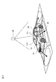
- FIG. 2 is a perspective view of a vehicle showing an example of the arrangement of the image pickup apparatus of the present embodiment mounted on the own vehicle.
- FIG. 3 is an example of a display image showing a bird's-eye view image generated by the image processing apparatus of the present embodiment.
- FIG. 4 is a plan view of a vehicle showing an example of the arrangement of the distance measuring device of the present embodiment mounted on the own vehicle.
- FIG. 5 is a plan view showing an example of a line pattern defining the parking area of the present embodiment.
- FIG. 6 is a plan view showing a parking route according to a comparative example of the present invention.
- FIG. 1 is a block diagram showing an example of the configuration of the parking support system according to the embodiment of the present invention.
- FIG. 2 is a perspective view of a vehicle showing an example of the arrangement of the image pickup apparatus of the present embodiment mounted on the own vehicle.
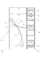
- FIG. 7 is a plan view showing an example of a parking route (example) calculated by the parking support device of the present embodiment.
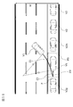
- FIG. 8 is a plan view showing another example of the parking route (example) calculated by the parking support device of the present embodiment.
- FIG. 9A is a plan view (No. 1) showing still another example of the parking route (Example) calculated by the parking support device of the present embodiment.
- FIG. 9B is a plan view (No. 2) showing still another example of the parking route (Example) calculated by the parking support device of the present embodiment.
- FIG. 9C is a plan view (No. 3) showing still another example of the parking route (Example) calculated by the parking support device of the present embodiment.
- FIG. 9D is a plan view (No.
- FIG. 10 is a plan view showing still another example of the parking route (example) calculated by the parking support device of the present embodiment.
- FIG. 11 is a time chart showing a running motion plan for parking assistance according to a comparative example of the present invention, (A) shows a time chart of vehicle speed, and (B) shows a time chart of steering angle.
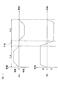
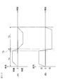
- FIG. 12 is a time chart showing an example of a running motion plan for parking support by the parking support device of the present embodiment, (A) shows a time chart of vehicle speed, and (B) shows a time chart of steering angle. show.
- FIG. 11 is a time chart showing a running motion plan for parking assistance according to a comparative example of the present invention, (A) shows a time chart of vehicle speed, and (B) shows a time chart of steering angle.
- FIG. 12 is a time chart showing an example of a running motion plan for parking support by the parking support device of the present embodiment, (A) shows a time chart of vehicle speed, and (B) shows a
- FIG. 13 is a time chart showing another example of a running motion plan for parking support by the parking support device of the present embodiment, (A) shows a time chart of vehicle speed, and (B) is a time of steering angle. Show the chart.
- FIG. 14 is a flowchart showing an example of the control procedure of the parking support device of the present embodiment of FIG.
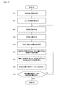
- FIG. 15 is a flowchart showing an example of the subroutine of step S6 of the flowchart shown in FIG.
- FIG. 1 is a block diagram showing a configuration of a parking support system 1000 according to an embodiment of the present invention.
- the parking support system 1000 of the present embodiment is a system for supporting a running operation for moving (parking) the own vehicle from the current position to the parking space.
- the parking support system 1000 of the present embodiment includes a parking support device 1, an image pickup device 2, an image processing device 3, a distance measuring device 4, a vehicle controller 5, a drive system 6, a vehicle speed sensor 7, and a steering angle. It includes a sensor 8.
- CAN Control Area Network
- the parking support device 1 of the present embodiment includes a control device 11 and an output device 12.
- the control device 11 of the present embodiment is accessible to a ROM 111 which is a ROM (Read Only Memory) in which a parking support program is stored and a CPU 112 which is a CPU (Central Processing Unit) which executes a program stored in the ROM 111. It includes a RAM 113 which is a RAM (Random Access Memory) that functions as a storage device.
- the output device 12 includes a display 121 which is a display device for presenting information such as a space in which the own vehicle can be parked to the driver.
- the parking support program stored in the ROM 111 of the present embodiment detects a parking space in which the own vehicle can park, presents the parking space on the display 121, and parks the own vehicle in the parking space set by the driver. It is a program that calculates a parking route and executes a control procedure that supports an operation for moving the own vehicle from the current position to the parking space.
- the parking support device 1 of the present embodiment manually performs at least one of automatic parking, steering, accelerator, and brake for automatically parking by automatically operating the steering, accelerator, and brake, and the rest. It can also be applied to semi-automatic parking, in which the operation of is automatically parked. Further, the parking support device 1 of the present embodiment can also be applied to parking support in which the driver is presented with a parking route and the driver operates the steering, accelerator, and brake to park the own vehicle in the parking space. Is. In the present embodiment, in the case of automatic parking and semi-automatic parking, an automatic return type switch such as a deadman switch is used. In the parking support device 1, when the deadman switch is pressed, the automatic driving of the own vehicle is executed, and when the pressing of the deadman switch is released, the automatic driving and the semi-automatic driving of the own vehicle are stopped.
- an automatic return type switch such as a deadman switch
- the parking support device 1 of the present embodiment is transmitted from a portable terminal device (smartphone, PDA, intelligent key for locking / unlocking the vehicle door) capable of exchanging information with the parking support device 1. It may be activated by a signal.
- the parking support device 1 of the present embodiment can also be applied to remote parking in which the driver operates and parks his / her own vehicle from outside the vehicle.
- the image pickup device 2 of the present embodiment, the image processing device 3 of the present embodiment, and the distance measuring device 4 of the present embodiment are located around the own vehicle, such as the front, side, and the entire circumference of the own vehicle. It is a device for detecting information on the driving environment including the presence of obstacles and other conditions around the own vehicle.
- the image pickup device 2 of the present embodiment is an in-vehicle device for recognizing environmental information around the own vehicle from images.
- the imaging device 2 of the present embodiment acquires environmental information around the own vehicle by taking an image of the surroundings of the own vehicle and acquiring image data including obstacles existing around the own vehicle.
- the image pickup device 2 includes a camera including an image pickup device such as a CCD, an ultrasonic camera, an infrared camera, and other cameras.
- the environmental information around the own vehicle acquired by the image pickup device 2 is output to the control device 11.
- FIG. 2 is a perspective view of the own vehicle V1 showing an example of the arrangement of the image pickup device 2 of the present embodiment mounted on the own vehicle V1.
- the image pickup device 2a is arranged on the front grille portion of the own vehicle V1
- the image pickup device 2b is arranged under the left door mirror
- the image pickup device 2c is arranged under the right door mirror
- the image pickup is performed in the vicinity of the rear bumper.
- the device 2d is arranged.
- the image pickup devices 2a to 2d may be cameras provided with a wide-angle lens having a large viewing angle. As shown in FIG.
- the image pickup device 2a images from the right front to the left front of the own vehicle V1
- the image pickup device 2b takes an image from the left front to the left rear of the own vehicle V1
- the image pickup device 2c takes an image.
- the image is taken from the left rear to the right rear of the own vehicle V1
- the image pickup device 2d images the image from the right rear to the right front of the own vehicle V1.
- the image processing device 3 of the present embodiment is a device for generating a bird's-eye view image showing the surrounding situation of the own vehicle V1 when the own vehicle V1 is viewed from an upper virtual viewpoint.
- the virtual viewpoint is, for example, the virtual viewpoint VP shown in FIG.
- the image processing device 3 generates a bird's-eye view image using a plurality of captured images acquired by using the image pickup device 2.
- the image processing performed to generate the bird's-eye view image in the image processing device 3 is not particularly limited. 116-07 (2007-10), 17-22. ”.
- the bird's-eye view image generated by the image processing device 3 is output to the control device 11 and presented to the driver by the display 121 shown in FIG.
- the display 121 shown in FIG. 2 is arranged between the driver's seat and the passenger seat at the upper part of the dashboard, but the installation position of the display 121 is not particularly limited and can be installed at an appropriate position.
- FIG. 3 is a display image showing an example of a bird's-eye view image generated by the image processing device 3 of the present embodiment.
- the traveling scene of the own vehicle V1 in FIG. 3 is a scene in which the own vehicle V1 is traveling in the parking lot in order to find the parking space PS.
- the bird's-eye view image IM1 generated by the image processing device 3 of the present embodiment is displayed on the left side of the display image shown in FIG. 3, and the monitoring image IM2 for monitoring the surroundings of the own vehicle V1 is displayed on the right side. Is displayed.
- the own vehicle V1 is displayed at the center of the bird's-eye view image IM1, and parking areas separated by white lines are displayed on the left and right sides of the own vehicle V1.
- the other vehicle V2 is displayed in the area where the other vehicle V2 is detected, and the own vehicle is displayed in the area where the own vehicle V1 can park, where no obstacles such as the other vehicle V2 are detected.
- a broken line frame indicating the parking space PS is displayed.
- the surveillance image IM2 displays an image acquired from the image pickup device 2a arranged on the front grille of the own vehicle V1 in order to present information on the surrounding environment in front of the own vehicle V1 in the current traveling direction. ..
- an obstacle such as another vehicle V2 is displayed.
- the distance measuring device 4 of the present embodiment is a device for calculating the relative distance and the relative speed between the own vehicle V1 and the object.
- the ranging device 4 is, for example, a laser radar, a millimeter wave radar or the like (LRF or the like), a LiDAR (light detection and ranking) unit, a radar device such as an ultrasonic radar, or a sonar.
- the ranging device 4 detects the presence / absence of an object, the position of the object, and the distance to the object based on the received signal of the radar device or sonar.
- the objects are, for example, obstacles, pedestrians, and other vehicles around the own vehicle V1.
- the information of the object detected by the distance measuring device 4 is output to the control device 11.
- the control device 11 of the present embodiment stops the own vehicle V1 and causes the object and the own vehicle V1 to collide with each other.
- the display 121 notifies the driver that a collision is likely to occur.
- FIG. 4 is a plan view of the own vehicle V1 showing an example of the arrangement of the distance measuring device 4 when the distance measuring device 4 of the present embodiment is mounted on the own vehicle V1.
- the own vehicle V1 shown in FIG. 4 includes a front ranging device 4a for detecting an object in front of the own vehicle V1, a lateral ranging device 4b for detecting an object on the right and left sides of the own vehicle V1. And a rear ranging device 4c for detecting an object behind the own vehicle V1.
- the own vehicle V1 shown in FIG. 4 is provided with ranging devices 4a-1 to 4a-4 as front ranging devices 4a, and ranging devices 4b-1 to 4b-4 as lateral ranging devices 4b, and is provided with rear ranging devices 4b-1 to 4b-4.
- the distance measuring devices 4c-1 to 4c-4 are provided.
- the distance measuring device 4 of the present embodiment can be installed, for example, in the bumper of the own vehicle V1. By arranging the distance measuring device 4 in this way, it is possible to prevent the calculation of the relative distance and the relative speed of the own vehicle V1 from the surrounding objects from becoming inaccurate.
- the vehicle controller 5 of the present embodiment is an in-vehicle computer such as an electronic control unit (ECU: Electronic Control Unit) for electronically controlling the drive system 6 that controls the operation of the own vehicle V1.
- the vehicle controller 5 controls a drive device, a braking device, and a steering device included in the drive system 6 to support a traveling operation for moving (parking) the own vehicle V1 from the current position to the parking space PS.
- the vehicle controller 5 receives a control command from the parking support device 1 based on the parking route, the target vehicle speed, and the target steering angle calculated in advance. The parking route, target vehicle speed, and target steering angle will be described later.
- the drive system 6 of the present embodiment includes an electric motor and / or an internal combustion engine as a traveling drive source, a power transmission device including a drive shaft and an automatic transmission for transmitting the output from these traveling drive sources to the drive wheels, and a power transmission device. It includes a driving device for controlling the wheels, a braking device for braking the wheels, and a steering device for controlling the total steering wheel according to the steering angle of the steering wheel (so-called steering wheel).
- the vehicle controller 5 receives a control command based on the parking route and the target vehicle speed calculated in advance from the parking support device 1.
- the vehicle controller 5 generates a control signal to the drive device of the drive system 6 based on the control command from the parking support device 1, and executes control of the driving behavior including acceleration / deceleration of the vehicle.
- the drive system 6 can autonomously control the vehicle speed of the own vehicle V1 by receiving the control signal from the vehicle controller 5.
- the drive system 6 of the present embodiment includes a steering device.
- the steering device includes a steering actuator, and the steering actuator includes a motor and the like attached to a column shaft of the steering.
- the steering device of the drive system 6 is controlled by the vehicle controller 5 so as to travel while maintaining a predetermined lateral position (position in the left-right direction of the vehicle) of the own vehicle with respect to the parking route calculated in advance.
- the vehicle controller 5 includes environmental information around the own vehicle V1 acquired by the image pickup device 2, a bird's-eye view image IM1 generated by the image processing device 3, and obstacles around the own vehicle V1 detected by the distance measuring device 4.
- the steering device is controlled by using at least one of the information of pedestrians and other vehicles.
- the parking support device 1 transmits a control command based on the parking route and the target steering angle calculated in advance to the vehicle controller 5. Then, the vehicle controller 5 generates a control signal to the steering device of the drive system 6 based on the control command from the parking support device 1, and executes the steering control of the own vehicle V1.
- the drive system 6 can autonomously control the steering of the own vehicle V1 by receiving the control signal from the vehicle controller 5.
- the vehicle speed sensor 7 of the present embodiment is a sensor provided in the drive device of the drive system 6 for detecting the vehicle speed of the own vehicle V1.
- the steering angle sensor 8 of the present embodiment is a sensor provided in the steering device of the drive system 6 for detecting the steering angle of the own vehicle V1.
- the vehicle speed of the own vehicle V1 detected by the vehicle speed sensor 7 and the steering angle of the own vehicle V1 detected by the steering angle sensor 8 are output to the control device 11 via the vehicle controller 5.
- the control device 11 of the present embodiment has an environment information acquisition function for acquiring environmental information around the own vehicle V1 by executing a parking support program stored in the ROM 111 by the CPU 112, and parking in which the own vehicle V1 can park.
- a parking space detection function that detects an area
- a parking space display function that displays the detected parking space PS as a bird's-eye view image IM1 on the display 121
- a parking route calculation function for calculating a parking route and a traveling operation planning function for planning a traveling operation for the own vehicle V1 to park along the calculated parking route are realized.
- the environmental information acquisition function of the control device 11 of the present embodiment is a function for the control device 11 to acquire information on the surrounding environment including the existence of obstacles located in the vicinity of the own vehicle V1.
- the control device 11 uses the environment information acquisition function to, for example, use the vehicle speed information of the own vehicle V1 detected by the vehicle speed sensor 7 and the steering angle information of the own vehicle V1 detected by the steering angle sensor 8 as information on the surrounding environment. get.
- the control device 11 has an environmental information acquisition function, for example, a vehicle position detection device (not shown) equipped with a GPS unit, a gyro sensor, and the like, and the positions of various facilities and specific points stored in the ROM.
- the position information of the own vehicle V1 detected by the three-dimensional high-precision map information including the information is acquired as information on the surrounding environment.
- the control device 11 of the present embodiment uses the information on the surrounding environment to determine whether or not the traveling scene of the own vehicle V1 is a scene in which the own vehicle V1 is parked in the parking space PS by the environmental information acquisition function. do.
- the control device 11 of the present embodiment parks the own vehicle V1 in the parking space PS. Judge that it is a scene.
- the control device 11 of the present embodiment is the own vehicle V1. Is determined to be a scene of parking in the parking space PS.
- the control device 11 of the present embodiment uses a communication device (not shown) to communicate with the outside of the vehicle (so-called road-to-vehicle communication) or from information on the surrounding environment acquired by vehicle-to-vehicle communication. It may be determined that the vehicle V1 is parked in the parking space PS. When it is determined that the vehicle V1 is parked in the parking space PS, the control device 11 of the present embodiment continues to execute the parking support program. On the other hand, for example, when it is determined from the information about the surrounding environment that the own vehicle V1 has left the parking lot and is traveling on the road, the control device 11 of the present embodiment parks the own vehicle V1. It is determined that the scene is not parked in the space PS. When it is determined that the vehicle V1 is not parked in the parking space PS, the control device 11 of the present embodiment stops the execution of the parking support program.
- a communication device not shown to communicate with the outside of the vehicle (so-called road-to-vehicle communication) or from information on the surrounding environment acquired by vehicle
- the control device 11 of the present embodiment takes an image by the environmental information acquisition function, for example, by the image pickup devices 2 attached to a plurality of places of the own vehicle V1.
- the captured image of the boundary line such as the white line around the own vehicle V1 and the objects existing in the surroundings is acquired as information on the surrounding environment.
- the control device 11 of the present embodiment acquires, for example, the detection results of the front ranging device 4a, the side ranging device 4b, and the rear ranging device 4c as information on the surrounding environment by the environment information acquisition function. ..
- the control device 11 of the present embodiment detects the parking space PS, which is a parking area in which the own vehicle V1 can park.
- the parking space detection function is used to detect the parking space PS.
- the parking space detection function of the control device 11 of the present embodiment is a function for detecting a parking area in which the own vehicle V1 can park by using the environmental information around the own vehicle V1 acquired by the environmental information acquisition function. ..
- the control device 11 of the present embodiment creates a bird's-eye view image IM1 by the image processing device 3 using the captured image acquired by the image pickup device 2 by the parking space detection function.
- the control device 11 of the present embodiment detects a line defining the boundary of the area from the created bird's-eye view image IM1 by the parking space detection function, and identifies a candidate line defining the parking area from the detected line.
- control device 11 of the present embodiment determines whether or not the specified line candidate defines the parking area by the parking space detection function, and determines that the specified line candidate defines the parking area. In this case, it is determined whether or not the own vehicle V1 can be parked in the detected parking area.
- the control device 11 of the present embodiment performs edge detection on the bird's-eye view image IM1 by the parking space detection function and calculates the brightness difference (contrast). do. Then, the control device 11 of the present embodiment identifies a pixel sequence having a brightness difference of a predetermined value or more from the bird's-eye view image IM1 by the parking space detection function, and calculates the line thickness and the line length.
- the color of the detected line does not necessarily have to be white, and may be red, yellow or other colors.
- the control device 11 of the present embodiment uses a known image processing technique such as pattern matching.
- the pattern used for pattern matching is stored in advance in the ROM 111 of the control device 11 of the present embodiment.
- FIG. 5A shows a scene in which the own vehicle V1 is about to park in the parking space PS1 which is a parking area where the own vehicle V1 can park, which is located between the other vehicle V2a and the other vehicle V2b.
- the lines defining the parking area corresponding to the parking space PS1 are the lines L1, the line L2, and the line L3, which are three of the sides forming the rectangle of the parking space PS1.
- the ROM 111 of the control device 11 of the present embodiment stores the combination of the line L1, the line L2, and the line L3 defining the parking area as a pattern corresponding to the scene of FIG. 5 (A).
- FIG. 5B shows a scene in which the own vehicle V1 is trying to parallel park in the parking space PS2 between the other vehicle V2c and the other vehicle V2d.
- the control device 11 of the present embodiment detects the line L4 as a line defining the parking area corresponding to the parking space PS2, and the image pickup device 2 detects the line L4 on the left side of the other vehicle V2c and the other vehicle V2d. Further detect curbs or walls (not shown) located in.
- the control device 11 of the present embodiment cannot define the parking area between the line L4 and the curb. Therefore, in the scene of FIG.
- the control device 11 of the present embodiment arranges the virtual line L5 behind the other vehicle V2c and the virtual line L6 in front of the other vehicle V2d. Then, when the line L4 detected by the image pickup apparatus 2 can define the parking area by the virtual lines L5 and L6, it is determined that the line L4 is the line defining the parking area.
- the ROM 111 of the control device 11 of the present embodiment shows a combination of the line L4, the virtual line L5 arranged behind the other vehicle V2c, and the virtual line L6 arranged in front of the other vehicle V2d. It is stored as a pattern corresponding to the scene of B).
- FIG. 5C shows a scene in which the own vehicle V1 is diagonally trying to park in the parking space PS3, which is a parking area where the own vehicle V1 can be parked, between the other vehicle V2e and the other vehicle V2f. ..
- the lines defining the parking area corresponding to the parking space PS3 are the lines L7, L8, L9, and L10, which are the sides forming the rectangle of the parking space PS3.
- the ROM 111 of the control device 11 of the present embodiment stores the combination of the line L7, the line L8, the line L9, and the line L10 that define the parking area as a pattern corresponding to the scene of FIG. 5C.
- the control device 11 of the present embodiment determines whether or not the control device 11 of the present embodiment has a candidate around the line specified as the line defining the parking area, which is more likely to correspond to the line defining the parking area than the specified line. Is detected. For example, when a line having a larger luminance difference is newly specified, the newly specified line is detected as a candidate for a line defining a parking area. On the other hand, when there is no candidate who is more likely to correspond to the line defining the parking area than the specified line, it is determined whether or not the specified line defines the parking area.
- the control device 11 of the present embodiment determines whether or not the specified candidate satisfies a predetermined condition.
- the predetermined conditions are, for example, (1) a length corresponding to a preset first line length distance threshold (for example, 15 [m] in the actual distance) in the line specified as a line candidate defining the parking area.
- S Does not include lines with a length longer than
- a preset first line-to-line distance range for example, in actual distance
- a preset second line length distance threshold for example, a length corresponding to 7 [m] in actual distance.
- a preset second line-to-line distance range for example, actual.
- a preset third line length distance threshold for example, 15 [m] in actual distance. It does not include a set of lines having a length greater than (corresponding length). If any one of the conditions (1), (2), or (3) is not satisfied, the control device 11 of the present embodiment determines that the specified line candidate does not define the parking area. do. On the other hand, when all the conditions (1) to (3) are satisfied, the control device 11 of the present embodiment determines that the specified line candidate defines the parking area and detects the parking area. ..
- the control device 11 of the present embodiment uses the information of the object detected by the distance measuring device 4 in the parking area. Determine if there is an obstacle in. For example, in the scene of FIG. 5A, it is determined whether or not there is an obstacle in the parking area by using the rear ranging device 4c of the own vehicle V1. Further, in the scene of FIG. 5B, it is determined whether or not there is an obstacle in the parking area by using the side distance measuring device 4b and the rear distance measuring device 4c of the own vehicle V1. Further, in the scene of FIG.
- the control device 11 of the present embodiment detects the parking area in which no obstacle exists as the parking space PS among the detected parking areas. On the other hand, the control device 11 of the present embodiment does not detect the detected parking area as the parking space PS when an obstacle exists in the detected parking area.
- the control device 11 of the present embodiment may determine whether or not the own vehicle V1 can park in the detected parking area by automatic driving. For example, if the parking area faces the wall side and the width of the passage required to control the driving operation of the autonomous driving cannot be secured, or if the parking area is surrounded by the pillars of the building, the driving operation of the autonomous driving If the information required to control the vehicle cannot be detected, the detected parking area does not correspond to a parking area that can be parked by automatic driving. Then, when the control device 11 of the present embodiment determines that there is no obstacle in the detected parking area and parking is possible by automatic operation, the detected parking area is detected as the parking space PS. On the other hand, the control device 11 of the present embodiment does not detect the detected parking area as the parking space PS when it is determined that there is no obstacle in the detected parking area but parking is not possible by automatic operation. ..
- the parking area does not necessarily have to be detected in order to detect the parking space PS.
- the control device 11 of the present embodiment may detect the area as a parking space PS.
- the control device 11 of the present embodiment may detect an area in a predetermined range in which no obstacle exists, and detect the area as a parking space PS. Further, the control device 11 of the present embodiment may detect the parking space PS by using the past traveling information.
- the parking space display function of the control device 11 of the present embodiment is a function for presenting the parking space PS to the driver by displaying the parking space PS detected by the control device 11 on the display 121.
- the control device 11 of the present embodiment presents the parking space PS to the driver in a broken line frame, for example, as shown in FIG. 3, by the parking space display function.
- the driver selects the parking space PS for parking the own vehicle V1 from the parking space PS shown in FIG.
- the parking space PS is selected, for example, by touching the screen of the display 121.
- the parking route calculation function of the control device 11 of the present embodiment is a function of calculating the parking route from the current position to the parking space PS in order for the own vehicle V1 to park in the selected parking space PS.
- the control device 11 of the present embodiment sets the turning position for the own vehicle V1 to make a turning by the parking route calculation function when the turning is required in the middle of the parking route, and the current state of the own vehicle V1.
- a parking route from the position to the parking space PS via the turning position is generated.
- the parking route generated by the control device 11 of the present embodiment steers the own vehicle V1 when the own vehicle V1 stops at the turning position based on the steering direction of the own vehicle V1 in the route from the turning position to the parking space.
- the route is such that the direction is the steering direction.
- the control device 11 according to the comparative example of the present invention is parked as shown in the plan view of FIG. Calculate the route. That is, the control device 11 according to the comparative example of the present invention detects the width W of the passage and the other vehicle V2 by the image pickup device 2 and the distance measuring device 4, and moves from the current position to the parking space PS via the turning position P. Therefore, the width W1 of the passage through which the own vehicle V1 can travel is calculated.
- the control device 11 sets the number of times of turning back, sets the turning back position P, and calculates a parking route for moving from the current position to the parking space PS via the turning back position P.
- the parking route shown in FIG. 6 is a section ZA in which the own vehicle V1 moves from the current position to the turning position P at a constant steering angle, and a section in which the own vehicle V1 moves from the turning position P to the parking space PS. Includes section ZB.
- the own vehicle V1 makes a stationary cut at the turning position P and steers the steering direction to the steering direction.
- the steering direction is steered in the steering direction while accelerating in the section ZB without making a stationary stop at the turning position. It is also possible to control various running movements. However, such a traveling operation gives a feeling of strangeness to the occupants of the own vehicle V1 because the movement of the own vehicle V1 changes significantly during acceleration. Further, in order to steer the steering direction in the steering direction, it is necessary to suppress the vehicle speed of the own vehicle V1 until the steering is completed.
- the own vehicle V1 needs to stop at the turning position P in order to change the traveling direction.
- the steering direction is not steered in the steering direction, but when the vehicle speed of the vehicle V1 is lowered to stop, the steering direction is changed to the steering direction.
- the control device 11 of the present embodiment steers the steering direction to the steering direction when the vehicle speed is lowered because the own vehicle V1 stops (in other words, before the turning position P). It suppresses the discomfort given to the occupants of the own vehicle V1, shortens the time required for steering, and shortens the time for suppressing the vehicle speed of the own vehicle V1 after turning back.
- the control device 11 of the present embodiment is shown in the plan view of FIG. 7 by the parking route calculation function.
- Calculate the parking route That is, the control device 11 of the present embodiment detects the width W of the passage and the other vehicle V2 by the image pickup device 2 and the distance measuring device 4, and moves from the current position to the parking space PS via the turning position P. The width W1 of the passage through which the own vehicle V1 can travel is calculated. Then, the control device 11 of the present embodiment sets the number of times of turning back, sets the turning back position P, and calculates the parking route for moving from the current position to the parking space PS via the turning back position P.
- the parking route shown in FIG. 7 is a section from the current position of the own vehicle V1 to the front of the turning position P, and is after the first section Z1 in which the own vehicle V1 moves at a constant steering angle and the first section Z1.
- the second section Z2, which is the section before the turning position P including the turning position P, and the section after the second section Z2, in the direction in which the own vehicle V1 moves to the parking space PS. Includes the third section Z3, which steers toward.
- the own vehicle V1 moves at a constant steering angle in the first section Z1, but in the parking route of the present embodiment, the own vehicle V1 does not necessarily move at a constant steering angle. good. Further, in the parking route of the present embodiment, the own vehicle V1 may move at a constant steering angle in the third section Z3.
- the control device 11 of the present embodiment sets the width W of the passage and the obstacles around the own vehicle V1 as, for example, the vehicle.
- the own vehicle V1 can travel only a part of the width W of the passage.
- the control device 11 of the present embodiment calculates the width of the passage through which the own vehicle V1 can travel in order to move from the current position to the parking space PS via the turning position P, which is calculated by the parking route calculation function.
- the turning position P is set using at least one of W1, the minimum turning radius of the own vehicle V1, the steering speed of the own vehicle V1, and the vehicle speed of the own vehicle V1.
- the control device 11 of the present embodiment may use the total length and the total width of the own vehicle V1.
- the width W1 of the passage through which the own vehicle V1 can travel, the minimum turning radius, the total length, and the total width of the own vehicle V1 are determined to be predetermined values depending on the traveling scene and the own vehicle V1.
- the steering speed of the own vehicle V1 and the vehicle speed of the own vehicle V1 can be set to appropriate values within a predetermined range.
- the control device 11 of the present embodiment sets the turning position P so that the time required for the own vehicle V1 to move from the current position to the parking space PS is the shortest, for example. For example, when the own vehicle V1 moves from the current position to the parking space PS, even if it can be moved by one turn, if it is determined that the movement is completed in a shorter time by moving by three turns, this implementation is carried out.
- the control device 11 of the form sets three turning positions P. Further, the control device 11 of the present embodiment may set the turning position P so that the number of times of turning required for the own vehicle V1 to move from the current position to the parking space PS is minimized. If the current position, the turning position P, and the parking space PS of the own vehicle V1 are set, the control device 11 of the present embodiment can calculate the parking route.
- the route of the second section Z2 of the present embodiment is self-directed when the own vehicle V1 stops at the turning position P based on the steering direction of the own vehicle V1 in the third section Z3 from the turning position P to the parking space PS.
- the route is such that the steering direction of the vehicle V1 is the steering direction.
- the steering direction is, for example, the direction of the steering angle of the own vehicle V1 or the direction in which the front wheels of the own vehicle V1 face the front of the own vehicle V1.
- the direction of the steering angle of the own vehicle V1 moving forward and the direction in which the front wheels of the own vehicle V1 face the front of the own vehicle V1 turn to the left. I'm steering.
- the control device 11 of the present embodiment determines that it is necessary to steer the steering direction from the left side to the right side before and after the turning position P, and when the own vehicle V1 stops at the turning position P, for example, itself.
- the route of the second section Z2 is calculated so that the direction of the steering angle of the vehicle V1 or the direction in which the front wheels of the own vehicle V1 face the front of the own vehicle V1 is on the right side.
- the route of the second section Z2 of the present embodiment may be a route such that the steering direction of the own vehicle V1 becomes the steering direction when the own vehicle V1 stops at the turning position P, but the own vehicle V1 is the turning position.
- the steering angle of the own vehicle V1 when stopped at P is set to be equal to the steering angle when the own vehicle V1 starts traveling from the turning position P toward the parking space PS in the third section. May be good. As a result, it is not necessary to change the steering direction when accelerating from the state where the own vehicle V1 is stopped, so that it is not necessary to suppress the vehicle speed of the own vehicle V1 until the steering is completed.
- control device 11 of the present embodiment can expand and contract the distance of the second section Z2 according to the width W1 of the passage in which the own vehicle V1 can travel.
- the traveling scene shown in FIG. 8 is the same as the traveling scene shown in FIG. 7, but the width W1 of the passage through which the own vehicle V1 can travel is narrower than that in FIG. 7.
- the control device 11 of the present embodiment uses the parking route calculation function to make the distance of the second section Z2 shorter than the distance of the second section Z2 shown in FIG. 7, and the parking route shown in the plan view of FIG. Is calculated.
- the distance of the second section Z2 shown in FIG. 8 can be expanded and contracted by changing the steering speed of the own vehicle V1 and / or the vehicle speed of the own vehicle V1.
- the distance of the second section Z2 when the distance of the second section Z2 is shortened, the steering speed of the own vehicle V1 is increased and / or the vehicle speed of the own vehicle V1 is decreased. On the other hand, when the distance of the second section Z2 is increased, the steering speed of the own vehicle V1 is decreased and / or the vehicle speed of the own vehicle V1 is increased. Further, the distance of the second section Z2 may be shortened in advance and extended during the parking support, or the distance may be increased or decreased during the control of the parking support.
- the route of the second section Z2 of the present embodiment can be set every time the own vehicle V1 turns back.
- the traveling scenes shown in FIGS. 9A to 9D are the same as the traveling scenes shown in FIGS. 7 and 8, but the width W1 of the passage through which the own vehicle V1 can travel is narrower than that in FIG.
- the control device 11 of the present embodiment sets three turning positions Pa to Pc by the parking route calculation function in order to move the own vehicle V1 from the current position to the parking space PS, and the first time. After the second turn, the route of the second section Z2 of the present embodiment is calculated.
- the control device 11 of the present embodiment detects the width W of the passage and the other vehicle V2 by the image pickup device 2 and the distance measuring device 4, and parks from the current position via the turning position P.
- the width W1 of the passage through which the own vehicle V1 can travel in order to move to the space PS is calculated.
- the control device 11 of the present embodiment sets the second turning position Pb shown in FIG. 9B after setting the first turning position Pa. In the second turning, the own vehicle V1 moves backward to the turning position Pb.
- the control device 11 of the present embodiment calculates the width W of the passage as the width W2 of the passage through which the own vehicle can travel. Further, the control device 11 of the present embodiment sets the third turning position Pc shown in FIG. 9C after setting the second turning position Pb. Similar to the second turn, the other vehicle V2, which is an obstacle, is not detected even in the third turn. Therefore, the control device 11 of the present embodiment calculates the width W of the passage as the width W2 of the passage through which the own vehicle can travel. do. Then, the control device 11 of the present embodiment calculates a parking route in which the own vehicle V1 moves from the current position to the parking space PS via the turning positions Pa, Pb, and Pc.
- the control device 11 of the present embodiment calculates the parking route in which the own vehicle V1 moves from the current position to the turning position Pa, as shown in FIG. 9A.
- the parking route shown in FIG. 9A includes a first section Z1a and a second section Z2a.
- the steering direction of the own vehicle V1 is changed when the own vehicle V1 stops at the turning position Pa based on the steering direction of the own vehicle V1 when going from the turning position Pa to the turning position Pb. It is a route that is in the rudder direction.
- control device 11 of the present embodiment determines that it is necessary to steer the steering direction from the left side to the right side before and after the turning position Pa, and when the own vehicle V1 stops at the turning position Pa, for example, itself.
- the route of the second section Z2a is calculated so that the direction of the steering angle of the vehicle V1 or the direction in which the front wheels of the own vehicle V1 face the front of the own vehicle V1 is on the right side.
- the control device 11 of the present embodiment calculates the parking route in which the own vehicle V1 moves from the turning position Pa to the turning position Pb shown in FIG. 9B.
- the parking route shown in FIG. 9B includes a first section Z1b and a second section Z2b.
- the steering direction of the own vehicle V1 is changed when the own vehicle V1 stops at the turning position Pb based on the steering direction of the own vehicle V1 when going from the turning position Pb to the turning position Pc. It is a route that is in the rudder direction.
- control device 11 of the present embodiment determines that it is necessary to steer the steering direction from the right side to the left side before and after the turning position Pb, and when the own vehicle V1 stops at the turning position Pb, for example, itself.
- the route of the second section Z2b is calculated so that the direction of the steering angle of the vehicle V1 or the direction in which the front wheels of the own vehicle V1 face the front of the own vehicle V1 is on the left side.
- the control device 11 of the present embodiment calculates the parking route in which the own vehicle V1 moves from the turning position Pb to the turning position Pc shown in FIG. 9C.
- the parking route shown in FIG. 9C comprises the first section Z1c.
- the own vehicle V1 can move from the turning position Pb to the turning position Pc at a constant steering angle, and it is not necessary to steer at the turning position Pc. Therefore, it is not necessary to set the second section Z2 of the present embodiment.
- the control device 11 of the present embodiment calculates a parking route in which the own vehicle V1 moves backward and straight from the turning position Pc to the parking space PS, as shown in FIG. 9D.
- the parking route shown in FIG. 9D comprises a third section Z3.
- control device 11 of the present embodiment can provide parking support even in parallel parking.
- the control device 11 of the present embodiment parallelizes the parking route by the parking route calculation function. calculate. That is, the control device 11 of the present embodiment detects the width W of the passage and the other vehicles V2g and V2h by the image pickup device 2 and the distance measuring device 4, and moves from the current position to the parking space PS via the turning position P. Therefore, the width W1 of the passage through which the own vehicle V1 can travel is calculated. In FIG. 10, the width W1 of the passage through which the own vehicle V1 can travel is equal to the detected width W of the passage.
- the control device 11 of the present embodiment sets the number of times of turning back, sets the turning back position P, and calculates the parking route in which the own vehicle V1 moves from the current position to the parking space PS via the turning back position P. ..
- the control device 11 of the present embodiment sets one turning position P.
- the control device 11 of the present embodiment calculates a parking route in which the own vehicle V1 moves from the current position to the parking space PS via the turning position P.
- the parallel parking parking route shown in FIG. 10 includes a first section Z1, a second section Z2, and a third section Z3.
- the steering direction of the own vehicle V1 is steered from the left side to the right side before and after the turning position P. Therefore, when the own vehicle V1 stops at the turning position P, the steering direction of the own vehicle V1 is steered to the right side.
- the route of the second section Z2 is calculated so as to be performed.
- the traveling operation planning function of the control device 11 of the present embodiment is a function of planning a traveling operation for the own vehicle V1 to park in the parking space PS along the parking route calculated by the parking route calculation function.
- the control device 11 of the present embodiment plans to control the vehicle speed and the steering angle of the own vehicle V1 so that the own vehicle V1 moves to the parking space PS along the parking route by the traveling motion planning function.
- FIG. 11 is a time chart showing a traveling operation plan when the own vehicle V1 moves from the current position to the parking space PS along the parking route according to the comparative example of the present invention as shown in FIG. 6, for example.
- FIG. 11A shows a time chart of vehicle speed
- FIG. 11B shows a time chart of steering angle.
- the horizontal axis of FIG. 11A represents time
- the vertical axis represents vehicle speed.
- the horizontal axis of FIG. 11B represents time and corresponds to the horizontal axis of FIG. 11A.
- the vertical axis of FIG. 11B represents the steering angle, and when the value is positive, the own vehicle V1 steers to the left, and when the value is negative, the own vehicle V1 steers to the right.
- the parking route shown in FIG. 6 includes a section ZA in which the own vehicle V1 moves from the current position to the turning position P, a turning position P in which the own vehicle V1 makes a stationary cut, and a parking space in which the own vehicle V1 moves from the turning position P.
- the vehicle speed and steering angle in section TA, the vehicle speed and steering angle in section TB, and the vehicle speed and steering angle in section TC shown in FIG. 11 are the traveling operations of the own vehicle V1 in section ZA, respectively. It corresponds to the stationary operation of the own vehicle V1 at the turning position P and the traveling operation of the own vehicle V1 in the section ZB.
- the stationary steering is performed in the section TB, the own vehicle V1 is stopped while the steering direction is steered in the steering direction. Therefore, it takes time to complete the running operation. Further, the stationary steering operation causes the tires to wear and the steering actuator to generate heat, which imposes a burden on the own vehicle V1.
- control device 11 of the present embodiment is, for example, the time chart of FIG. 12 when the own vehicle V1 moves from the current position to the parking space PS along the parking route of the present embodiment shown in FIG. Generate the driving operation plan shown in.
- the notation method of the vehicle speed in FIG. 12 (A) and the steering angle in FIG. 12 (B) conforms to FIGS. 11 (A) and 11 (B).
- the parking route shown in FIG. 7 includes a first section Z1, a second section Z2, and a third section Z3.
- the vehicle speed and steering angle in section T1, the vehicle speed and steering angle in section T2, and the vehicle speed and steering angle in section T3 shown in FIG. 12 are the traveling operations of the own vehicle V1 in the first section Z1 shown in FIG. 7, respectively. It corresponds to the traveling operation of the own vehicle V1 in the second section Z2 shown in 7 and the traveling operation of the own vehicle V1 in the third section Z3 shown in FIG.
- the vehicle speed becomes 0 at the turning position P, that is, the steering is performed from left to right before the own vehicle V1 stops. Therefore, the parking according to the comparative example of the present invention.
- the own vehicle V1 can quickly start retreating after stopping at the turning position P. As a result, the time required for parking can be shortened. Further, since it is not necessary to steer when accelerating in the section T3 of FIG. 12, the acceleration in the section T3 can be performed at a larger acceleration than that shown in FIG. As a result, the time required for parking can be shortened.
- control device 11 of the present embodiment travels, for example, as shown in the time chart of FIG. 13 when the own vehicle V1 moves from the current position to the parking space PS along the parking route of the present embodiment shown in FIG. Generate an operation plan.
- the notation method of the vehicle speed in FIG. 13 (A) and the steering angle in FIG. 13 (B) conforms to FIGS. 11 (A) and 11 (B).
- the parking route shown in FIG. 8 includes the first section Z1, the second section Z2, and the third section Z3, like the parking route shown in FIG. 7, but the distance of the second section Z2 shown in FIG. 8 is FIG. 7. It is shorter than the second section Z2 shown in.
- the vehicle speed and steering angle in section T4, the vehicle speed and steering angle in section T5, and the vehicle speed and steering angle in section T6 shown in FIG. 13 are the traveling operations of the own vehicle V1 in the first section Z1 shown in FIG. 8, respectively. It corresponds to the traveling operation of the own vehicle V1 in the second section Z2 shown in 8 and the traveling operation of the own vehicle V1 in the third section Z3 shown in FIG.
- the traveling motion plan shown in FIG. 13 is the same as the traveling motion plan of FIG. 12 except for the section T5.
- the own vehicle V1 is stopped at a larger acceleration than the section T2 of FIG. 12 in the section T5, and the steering is steered at a larger steering speed. conduct.
- the distance of the second section Z2 shown in FIG. 8 can be made shorter than the distance of the second section Z2 shown in FIG.
- the traveling motion plan shown in FIG. 13 since the section T5 is shorter than the section T2, the time required for parking can be shortened as compared with the traveling motion plan shown in FIG.
- FIG. 14 is an example of a flowchart showing the basic processing of the parking support processing of the present embodiment.
- FIG. 15 is a flowchart showing an example of the subroutine in step S6 of FIG.
- the travel control process described below is executed by the control device 11 at predetermined time intervals. Further, in the following, the control device 11 of the present embodiment will be described as determining that the vehicle V1 is a traveling scene in which the vehicle V1 is parked in the parking space PS based on the information on the surrounding environment and executes the parking support program.
- step S1 of FIG. 14 the control device 11 of the present embodiment uses the environmental information acquisition function to image the surroundings of the own vehicle using the image pickup device 2, and obtains image data including obstacles existing around the own vehicle. get. Further, in step S1, the control device 11 of the present embodiment uses the distance measuring device 4 to determine the presence / absence of obstacles, pedestrians, other vehicles, and the position of the object around the own vehicle V1 by using the environmental information acquisition function. Detect the distance to the object.
- step S2 the control device 11 of the present embodiment creates a bird's-eye view image IM1 by the image processing device 3 using the image acquired by the image pickup device 2 by the parking space detection function.
- step S3 the control device 11 of the present embodiment detects the parking area from the bird's-eye view image IM1 by the parking space detection function, and detects the parking space PS from the parking area by using the image pickup device 2 and the distance measuring device 4. ..
- step S4 the control device 11 of the present embodiment presents the parking space PS to the driver using the display 121 by the parking space display function.
- step S5 the control device 11 of the present embodiment determines whether or not the driver has selected the parking space PS for parking the own vehicle V1 from the parking space PS. If the driver has not selected the parking space PS for parking the own vehicle V1 from the parking space PS (step S5: NO), the process returns to step S4, and the control device 11 of the present embodiment sets the parking space PS. Present it to the driver. On the other hand, when the driver selects the parking space PS for parking the own vehicle V1 from the parking space PS (step S5: YES), the process proceeds to step S6.
- step S6 the control device 11 of the present embodiment calculates the parking route in which the own vehicle V1 moves from the current position to the parking space PS selected by the driver by the parking route calculation function.
- step S7 the control device 11 of the present embodiment plans a traveling operation for the own vehicle V1 to park along the calculated parking route by the traveling operation planning function.
- step S8 the control device 11 of the present embodiment uses the vehicle controller 5, the drive system 6, the vehicle speed sensor 7, and the steering angle sensor 8 according to the calculated parking route and the planned running operation. Carry out parking assistance for vehicle V1.
- step S61 of FIG. 15 the control device 11 of the present embodiment detects an obstacle such as the width W of the passage and the other vehicle V2 by using the image pickup device 2 and the distance measuring device 4 by the parking route calculation function. ..
- step S62 the control device 11 of the present embodiment calculates the widths W1 and W2 of the passage in which the own vehicle can travel by the parking route calculation function.
- step S63 the control device 11 of the present embodiment uses the parking route calculation function to determine the width W1 of the passage through which the own vehicle V1 can travel, the minimum turning radius of the own vehicle V1, the steering speed of the own vehicle V1, and the own vehicle. The number of turns is set using at least one of the vehicle speeds of V1. Further, in step S64, the control device 11 of the present embodiment sets the turn-back position P by using the set turn-back number of times by the parking route calculation function.
- step S65 the control device 11 of the present embodiment determines the steering direction at the turning position by the parking route calculation function.
- step S66 the control device 11 of the present embodiment uses the turning position P set by the parking route calculation function and the determined steering direction, and the steering direction of the own vehicle V1 becomes the steering direction. , Calculate the route from the current position to the turning position P.
- step S67 the control device 11 of the present embodiment uses the parking route calculation function to make the steering direction of the own vehicle V1 the steering direction from the turning position to the next turning position. Calculate the route of.
- step S67 is an arbitrary step and is shown by a broken line in FIG.
- step S68 the control device 11 of the present embodiment calculates the route from the turning position to the parking space by the parking route calculation function.
- step S69 the control device 11 of the present embodiment determines whether or not the parking route for the own vehicle V1 to move from the current position to the parking space PS can be calculated by the parking route calculation function. If the parking route for the own vehicle V1 to move from the current position to the parking space PS can be calculated (step S69: YES), the process proceeds to step S7 in FIG. Therefore, the traveling operation for the own vehicle V1 to park along the calculated parking route is planned. On the other hand, if the parking route on which the own vehicle V1 moves from the current position to the parking space PS cannot be calculated (step S69: NO), the process returns to step S63, and the control device 11 of the present embodiment calculates the parking route. Depending on the function, the number of cutbacks is set again.
- the parking space PS for parking the own vehicle V1 is detected, and the turning position P for the own vehicle V1 to turn back is set. It sets, generates a parking route from the current position of the own vehicle V1 to the parking space PS via the turning position P, and autonomously controls the own vehicle V1 along the parking route.
- the parking route after determining the steering direction of the own vehicle V1 in the route from the turning position P to the parking space PS, when the own vehicle V1 stops at the turning position P, the steering direction of the own vehicle V1 is changed.
- the route from the current position of the own vehicle V1 to the turning position P so as to be in the steering direction is included.
- the steering direction is steered in the steering direction, and it is possible to suppress the discomfort that the traveling operation of the own vehicle V1 gives to the occupants.
- the amount of stationary steering when the own vehicle V1 is steered can be suppressed, the time required for steering can be shortened, and the time required for parking can be shortened.
- the steering direction of the own vehicle V1 is the steering direction, so that the amount of steering after turning back can be suppressed.
- the time for suppressing the vehicle speed of the own vehicle V1 after turning back can be shortened, and the time required for parking can be shortened.
- the steering angle of the own vehicle V1 when the own vehicle V1 stops at the turning position P is set from the turning position P toward the parking space PS.
- the angle is set to be equal to the steering angle when the own vehicle V1 starts traveling.
- the parking route is a section from the current position of the own vehicle V1 to the front of the turning position P, and the own vehicle has a constant steering angle.
- the parking support device 1 and the parking support method according to the present embodiment when the passage width W1 that can be traveled to move from the current position of the own vehicle V1 to the parking space PS via the turning position P is narrow, The distance of the second section Z2 is relatively shortened as compared with the case where the passage width W1 is wide. As a result, even when the passage width W1 is narrow, the amount of stationary steering when the own vehicle V1 is steered can be suppressed, the time required for steering can be shortened, and the time required for parking can be shortened. .. Further, even when the passage width W1 is narrow, the amount of steering after turning back can be suppressed, the time for suppressing the vehicle speed of the own vehicle V1 can be shortened, and the time required for parking can be shortened.
- a predetermined passage width W1 that can be traveled to move from the current position of the own vehicle V1 to the parking space PS via the turning position P is predetermined.
- the distance of the second section Z2 is relatively shortened as compared with the case where the passage width W1 is equal to or more than the predetermined value.
- the predetermined value of the passage width W1 to be determined in advance can be appropriately set by using the minimum turning radius, the total length, the total width, and the like of the own vehicle V1.
- the distance between the two sections Z2 is shortened.
- the steering speed of the own vehicle V1 is relatively increased and / or , The vehicle speed of the own vehicle V1 is relatively reduced.
- the passage width W1 is narrow, the amount of stationary steering when the own vehicle V1 is steered can be suppressed, the time required for steering can be shortened, and the time required for parking can be shortened. ..
- the amount of steering after turning back can be suppressed, the time for suppressing the vehicle speed of the own vehicle V1 can be shortened, and the time required for parking can be shortened.
- a predetermined passage width W1 that can be traveled to move from the current position of the own vehicle V1 to the parking space PS via the turning position P is predetermined. If it is less than the value, the steering speed of the own vehicle V1 is relatively increased and / or the vehicle speed of the own vehicle V1 is relatively decreased. As a result, even when the passage width W1 is narrow, the amount of stationary steering when the own vehicle V1 is steered can be suppressed, the time required for steering can be shortened, and the time required for parking can be shortened. .. Further, even when the passage width W1 is narrow, the amount of steering after turning back can be suppressed, the time for suppressing the vehicle speed of the own vehicle V1 can be shortened, and the time required for parking can be shortened.
- the narrower the passage width W1 that can be traveled to move from the current position of the own vehicle V1 to the parking space PS via the turning position P the more the self The steering speed of the vehicle V1 is increased and / or the vehicle speed of the own vehicle V1 is relatively decreased.
- the passage width W1 is narrow, the amount of stationary steering when the own vehicle V1 is steered can be suppressed, the time required for steering can be shortened, and the time required for parking can be shortened. ..
- the passage width W1 is narrow, the amount of steering after turning back can be suppressed, the time for suppressing the vehicle speed of the own vehicle V1 can be shortened, and the time required for parking can be shortened.
- the distance of the second section Z2 is at least the passage width W1, the minimum turning radius of the own vehicle V1, and the steering speed of the own vehicle V1. , Set using the vehicle speed of the own vehicle V1. Thereby, in order to shorten the time required for steering and shorten the time required for parking, a more appropriate distance of the second section Z2 can be calculated.
- Sections T3, T6 Sections corresponding to the third section ZA ... Sections where the own vehicle moves from the current position to the turning position P at a constant steering angle ZB ...
- the own vehicle V1 moves from the turning position P to the parking space.
Landscapes
- Engineering & Computer Science (AREA)
- Mechanical Engineering (AREA)
- Transportation (AREA)
- Automation & Control Theory (AREA)
- Human Computer Interaction (AREA)
- Chemical & Material Sciences (AREA)
- Combustion & Propulsion (AREA)
- Physics & Mathematics (AREA)
- General Physics & Mathematics (AREA)
- Traffic Control Systems (AREA)
- Steering Control In Accordance With Driving Conditions (AREA)
- Control Of Driving Devices And Active Controlling Of Vehicle (AREA)
Priority Applications (5)
| Application Number | Priority Date | Filing Date | Title |
|---|---|---|---|
| US17/630,830 US20220219678A1 (en) | 2020-02-10 | 2020-02-10 | Parking Assist Method and Parking Assist Apparatus |
| CN202080054845.2A CN114174131A (zh) | 2020-02-10 | 2020-02-10 | 停车辅助方法及停车辅助装置 |
| PCT/JP2020/005116 WO2021161378A1 (ja) | 2020-02-10 | 2020-02-10 | 駐車支援方法及び駐車支援装置 |
| JP2021577728A JP7176651B2 (ja) | 2020-02-10 | 2020-02-10 | 駐車支援方法及び駐車支援装置 |
| EP20919302.8A EP4105087A4 (en) | 2020-02-10 | 2020-02-10 | PARKING ASSISTANCE PROCEDURE AND PARKING ASSISTANCE DEVICE |
Applications Claiming Priority (1)
| Application Number | Priority Date | Filing Date | Title |
|---|---|---|---|
| PCT/JP2020/005116 WO2021161378A1 (ja) | 2020-02-10 | 2020-02-10 | 駐車支援方法及び駐車支援装置 |
Publications (1)
| Publication Number | Publication Date |
|---|---|
| WO2021161378A1 true WO2021161378A1 (ja) | 2021-08-19 |
Family
ID=77291430
Family Applications (1)
| Application Number | Title | Priority Date | Filing Date |
|---|---|---|---|
| PCT/JP2020/005116 Ceased WO2021161378A1 (ja) | 2020-02-10 | 2020-02-10 | 駐車支援方法及び駐車支援装置 |
Country Status (5)
| Country | Link |
|---|---|
| US (1) | US20220219678A1 (https=) |
| EP (1) | EP4105087A4 (https=) |
| JP (1) | JP7176651B2 (https=) |
| CN (1) | CN114174131A (https=) |
| WO (1) | WO2021161378A1 (https=) |
Families Citing this family (3)
| Publication number | Priority date | Publication date | Assignee | Title |
|---|---|---|---|---|
| KR20230037917A (ko) * | 2021-09-10 | 2023-03-17 | 현대자동차주식회사 | 자율주행 차량용 통합조작장치의 경고신호 발생방법 |
| US20250054318A1 (en) * | 2023-08-07 | 2025-02-13 | Toyota Motor Engineering & Manufacturing North America, Inc. | Systems, vehicles, and methods for vehicle environment detection based on blocked view |
| DE102024207886A1 (de) * | 2024-08-20 | 2026-02-26 | Robert Bosch Gesellschaft mit beschränkter Haftung | Verfahren zur Reduktion von Lenkbewegungen im Stillstand in der Bewegungsregelung automatisierter Fahrzeuge bei Parkmanövern |
Citations (4)
| Publication number | Priority date | Publication date | Assignee | Title |
|---|---|---|---|---|
| JP2010202010A (ja) * | 2009-03-02 | 2010-09-16 | Aisin Seiki Co Ltd | 駐車支援装置 |
| JP2015081022A (ja) * | 2013-10-23 | 2015-04-27 | クラリオン株式会社 | 自動駐車制御装置および駐車支援装置 |
| JP6062406B2 (ja) | 2014-09-12 | 2017-01-18 | アイシン精機株式会社 | 駐車支援装置および駐車支援方法 |
| JP2019064431A (ja) * | 2017-09-29 | 2019-04-25 | パナソニックIpマネジメント株式会社 | 駐車支援装置 |
Family Cites Families (14)
| Publication number | Priority date | Publication date | Assignee | Title |
|---|---|---|---|---|
| DE102005061909A1 (de) * | 2005-12-23 | 2007-07-05 | Volkswagen Ag | Parklenkassistenzsystem und Verfahren zum Betreiben eines Parklenkassistenzsystems |
| WO2008081655A1 (ja) * | 2006-12-28 | 2008-07-10 | Kabushiki Kaisha Toyota Jidoshokki | 駐車支援装置、駐車支援装置部品、駐車支援方法、駐車支援プログラム、車両走行パラメータの算出方法及び算出プログラム、車両走行パラメータ算出装置並びに車両走行パラメータ算出装置部品 |
| JP4900326B2 (ja) * | 2008-06-10 | 2012-03-21 | 日産自動車株式会社 | 駐車支援装置及び駐車支援方法 |
| JP5403330B2 (ja) * | 2009-02-25 | 2014-01-29 | アイシン精機株式会社 | 駐車支援装置 |
| DE102009027289A1 (de) * | 2009-05-11 | 2010-11-18 | Robert Bosch Gmbh | Verfahren und Vorrichtung zur Einparkunterstützung eines Fahrzeugs |
| DE102009027941A1 (de) * | 2009-07-22 | 2011-01-27 | Robert Bosch Gmbh | Vorrichtung zum Rangieren eines Fahrzeugs mittels Rangierzügen mit wenigstens einer Trajektorie |
| JP5477515B2 (ja) * | 2011-08-12 | 2014-04-23 | トヨタ自動車株式会社 | 駐車支援装置 |
| US10214206B2 (en) * | 2015-07-13 | 2019-02-26 | Magna Electronics Inc. | Parking assist system for vehicle |
| JP6569362B2 (ja) * | 2015-07-31 | 2019-09-04 | アイシン精機株式会社 | 駐車支援装置 |
| EP3686084B1 (en) * | 2015-10-22 | 2023-08-30 | Nissan Motor Co., Ltd. | Parking support method and parking support device |
| US20200156703A1 (en) * | 2017-06-26 | 2020-05-21 | Hitachi Automotive Systems, Ltd. | Driving support device |
| TWI656519B (zh) * | 2017-12-12 | 2019-04-11 | Industrial Technology Research Institute | 停車導引系統及其方法與自動停車系統 |
| JP7133336B2 (ja) * | 2018-04-06 | 2022-09-08 | 日立Astemo株式会社 | 駐車支援装置 |
| JP7117183B2 (ja) * | 2018-07-17 | 2022-08-12 | 日立Astemo株式会社 | 車両制御装置 |
-
2020
- 2020-02-10 CN CN202080054845.2A patent/CN114174131A/zh active Pending
- 2020-02-10 JP JP2021577728A patent/JP7176651B2/ja active Active
- 2020-02-10 WO PCT/JP2020/005116 patent/WO2021161378A1/ja not_active Ceased
- 2020-02-10 US US17/630,830 patent/US20220219678A1/en active Pending
- 2020-02-10 EP EP20919302.8A patent/EP4105087A4/en active Pending
Patent Citations (4)
| Publication number | Priority date | Publication date | Assignee | Title |
|---|---|---|---|---|
| JP2010202010A (ja) * | 2009-03-02 | 2010-09-16 | Aisin Seiki Co Ltd | 駐車支援装置 |
| JP2015081022A (ja) * | 2013-10-23 | 2015-04-27 | クラリオン株式会社 | 自動駐車制御装置および駐車支援装置 |
| JP6062406B2 (ja) | 2014-09-12 | 2017-01-18 | アイシン精機株式会社 | 駐車支援装置および駐車支援方法 |
| JP2019064431A (ja) * | 2017-09-29 | 2019-04-25 | パナソニックIpマネジメント株式会社 | 駐車支援装置 |
Non-Patent Citations (1)
| Title |
|---|
| See also references of EP4105087A4 |
Also Published As
| Publication number | Publication date |
|---|---|
| US20220219678A1 (en) | 2022-07-14 |
| CN114174131A (zh) | 2022-03-11 |
| JP7176651B2 (ja) | 2022-11-22 |
| JPWO2021161378A1 (https=) | 2021-08-19 |
| EP4105087A4 (en) | 2023-03-22 |
| EP4105087A1 (en) | 2022-12-21 |
Similar Documents
| Publication | Publication Date | Title |
|---|---|---|
| JP7043450B2 (ja) | 車両制御装置、車両制御方法、及びプログラム | |
| JP6547836B2 (ja) | 駐車支援方法及び駐車支援装置 | |
| JP6562081B2 (ja) | 駐車スペースの枠線の検出方法および装置 | |
| US10366611B2 (en) | Parking support information display method and parking support device | |
| CN112124097A (zh) | 驻车辅助系统 | |
| JP2019182305A (ja) | 車両制御装置、車両制御方法、およびプログラム | |
| JP7035408B2 (ja) | 車両走行制御方法及び装置 | |
| JP7379033B2 (ja) | 運転支援方法及び運転支援装置 | |
| EP4239613A1 (en) | Parking assistance method and parking assistance device | |
| JP7176651B2 (ja) | 駐車支援方法及び駐車支援装置 | |
| CN116674557A (zh) | 车辆自主变道动态规划方法、装置和域控制器 | |
| WO2023067793A1 (ja) | 運転支援方法及び運転支援装置 | |
| EP4559772A1 (en) | Narrow-lane pass-through method and apparatus, and vehicle | |
| JP2020063044A (ja) | 出庫支援方法及び装置 | |
| JP7424144B2 (ja) | 車両用表示装置および車両用表示方法 | |
| JP7726001B2 (ja) | 車両管理装置、車両管理方法及び車両管理システム並びに走行制御システム及び走行制御装置 | |
| RU2791347C1 (ru) | Способ помощи при парковке и устройство помощи при парковке | |
| JP2023169524A (ja) | 車両の運転支援方法及び運転支援装置 | |
| JP2023167861A (ja) | 車両の運転支援方法及び運転支援装置 | |
| JP7743938B2 (ja) | 運転支援方法及び運転支援装置 | |
| JP7768360B2 (ja) | 情報提供装置及び情報提供方法 | |
| JP7532242B2 (ja) | 走行支援方法および走行支援装置 | |
| JP7782710B2 (ja) | 運転支援方法及び運転支援装置 | |
| JP7698496B2 (ja) | 駐車支援装置 | |
| JP7782682B2 (ja) | 情報提供装置及び情報提供方法 |
Legal Events
| Date | Code | Title | Description |
|---|---|---|---|
| 121 | Ep: the epo has been informed by wipo that ep was designated in this application |
Ref document number: 20919302 Country of ref document: EP Kind code of ref document: A1 |
|
| ENP | Entry into the national phase |
Ref document number: 2021577728 Country of ref document: JP Kind code of ref document: A |
|
| NENP | Non-entry into the national phase |
Ref country code: DE |
|
| ENP | Entry into the national phase |
Ref document number: 2020919302 Country of ref document: EP Effective date: 20220912 |