WO2021161378A1 - Parking assist method and parking assist apparatus - Google Patents
Parking assist method and parking assist apparatus Download PDFInfo
- Publication number
- WO2021161378A1 WO2021161378A1 PCT/JP2020/005116 JP2020005116W WO2021161378A1 WO 2021161378 A1 WO2021161378 A1 WO 2021161378A1 JP 2020005116 W JP2020005116 W JP 2020005116W WO 2021161378 A1 WO2021161378 A1 WO 2021161378A1
- Authority
- WO
- WIPO (PCT)
- Prior art keywords
- vehicle
- parking
- section
- present
- route
- Prior art date
Links
- 238000000034 method Methods 0.000 title claims abstract description 35
- 230000003247 decreasing effect Effects 0.000 claims description 6
- 230000006870 function Effects 0.000 description 55
- 240000004050 Pentaglottis sempervirens Species 0.000 description 18
- 235000004522 Pentaglottis sempervirens Nutrition 0.000 description 18
- 238000012545 processing Methods 0.000 description 18
- 238000001514 detection method Methods 0.000 description 14
- 230000007613 environmental effect Effects 0.000 description 14
- 230000033001 locomotion Effects 0.000 description 13
- 230000000052 comparative effect Effects 0.000 description 9
- 230000001133 acceleration Effects 0.000 description 6
- 238000003384 imaging method Methods 0.000 description 5
- 238000005259 measurement Methods 0.000 description 4
- 230000005540 biological transmission Effects 0.000 description 3
- 238000004891 communication Methods 0.000 description 3
- 238000010586 diagram Methods 0.000 description 2
- 238000012544 monitoring process Methods 0.000 description 2
- 125000002066 L-histidyl group Chemical group [H]N1C([H])=NC(C([H])([H])[C@](C(=O)[*])([H])N([H])[H])=C1[H] 0.000 description 1
- 239000003086 colorant Substances 0.000 description 1
- 238000002485 combustion reaction Methods 0.000 description 1
- 238000007796 conventional method Methods 0.000 description 1
- 238000003708 edge detection Methods 0.000 description 1
- 238000009434 installation Methods 0.000 description 1
- 238000003825 pressing Methods 0.000 description 1
- 238000004904 shortening Methods 0.000 description 1
Images


Classifications
-
- B—PERFORMING OPERATIONS; TRANSPORTING
- B60—VEHICLES IN GENERAL
- B60W—CONJOINT CONTROL OF VEHICLE SUB-UNITS OF DIFFERENT TYPE OR DIFFERENT FUNCTION; CONTROL SYSTEMS SPECIALLY ADAPTED FOR HYBRID VEHICLES; ROAD VEHICLE DRIVE CONTROL SYSTEMS FOR PURPOSES NOT RELATED TO THE CONTROL OF A PARTICULAR SUB-UNIT
- B60W30/00—Purposes of road vehicle drive control systems not related to the control of a particular sub-unit, e.g. of systems using conjoint control of vehicle sub-units, or advanced driver assistance systems for ensuring comfort, stability and safety or drive control systems for propelling or retarding the vehicle
- B60W30/06—Automatic manoeuvring for parking
-
- B—PERFORMING OPERATIONS; TRANSPORTING
- B62—LAND VEHICLES FOR TRAVELLING OTHERWISE THAN ON RAILS
- B62D—MOTOR VEHICLES; TRAILERS
- B62D15/00—Steering not otherwise provided for
- B62D15/02—Steering position indicators ; Steering position determination; Steering aids
- B62D15/027—Parking aids, e.g. instruction means
- B62D15/0285—Parking performed automatically
-
- B—PERFORMING OPERATIONS; TRANSPORTING
- B60—VEHICLES IN GENERAL
- B60R—VEHICLES, VEHICLE FITTINGS, OR VEHICLE PARTS, NOT OTHERWISE PROVIDED FOR
- B60R99/00—Subject matter not provided for in other groups of this subclass
-
- B—PERFORMING OPERATIONS; TRANSPORTING
- B60—VEHICLES IN GENERAL
- B60W—CONJOINT CONTROL OF VEHICLE SUB-UNITS OF DIFFERENT TYPE OR DIFFERENT FUNCTION; CONTROL SYSTEMS SPECIALLY ADAPTED FOR HYBRID VEHICLES; ROAD VEHICLE DRIVE CONTROL SYSTEMS FOR PURPOSES NOT RELATED TO THE CONTROL OF A PARTICULAR SUB-UNIT
- B60W60/00—Drive control systems specially adapted for autonomous road vehicles
- B60W60/001—Planning or execution of driving tasks
-
- G—PHYSICS
- G08—SIGNALLING
- G08G—TRAFFIC CONTROL SYSTEMS
- G08G1/00—Traffic control systems for road vehicles
- G08G1/16—Anti-collision systems
- G08G1/168—Driving aids for parking, e.g. acoustic or visual feedback on parking space
-
- B—PERFORMING OPERATIONS; TRANSPORTING
- B60—VEHICLES IN GENERAL
- B60W—CONJOINT CONTROL OF VEHICLE SUB-UNITS OF DIFFERENT TYPE OR DIFFERENT FUNCTION; CONTROL SYSTEMS SPECIALLY ADAPTED FOR HYBRID VEHICLES; ROAD VEHICLE DRIVE CONTROL SYSTEMS FOR PURPOSES NOT RELATED TO THE CONTROL OF A PARTICULAR SUB-UNIT
- B60W2420/00—Indexing codes relating to the type of sensors based on the principle of their operation
- B60W2420/40—Photo or light sensitive means, e.g. infrared sensors
- B60W2420/403—Image sensing, e.g. optical camera
-
- B—PERFORMING OPERATIONS; TRANSPORTING
- B60—VEHICLES IN GENERAL
- B60W—CONJOINT CONTROL OF VEHICLE SUB-UNITS OF DIFFERENT TYPE OR DIFFERENT FUNCTION; CONTROL SYSTEMS SPECIALLY ADAPTED FOR HYBRID VEHICLES; ROAD VEHICLE DRIVE CONTROL SYSTEMS FOR PURPOSES NOT RELATED TO THE CONTROL OF A PARTICULAR SUB-UNIT
- B60W2720/00—Output or target parameters relating to overall vehicle dynamics
- B60W2720/24—Direction of travel
Definitions
- the present invention relates to a parking support method and a parking support device.
- the parking space length at the frontage of the vehicle is equal to or greater than the sum of the total length of the vehicle and the predetermined length, and the parking space length is equal to or greater than the sum of the total length of the vehicle and the predetermined length. If the parking space length is less than the sum of the total length of the vehicle and the predetermined length, the vehicle is parked on the route with a parallel parking.
- a parking support method for providing parking support is known (Patent Document 1).
- the above-mentioned conventional technique has a problem that when parking assistance of a vehicle is performed on a route including turning back, the steering direction of the own vehicle becomes the opposite direction after turning back, so that the time required for parking becomes long.
- An object to be solved by the present invention is to provide a parking support method and a parking support device capable of shortening the time required for parking when parking support of a vehicle is performed on a route including turning back.
- the present invention determines the steering direction of the own vehicle on the route from the turning position to the parking space, and when the own vehicle stops at the turning position, the steering direction of the own vehicle becomes the turning direction.
- the above problem is solved by generating a path from the current position of the vehicle to the turning position.
- the present invention it is possible to shorten the time required for parking when the vehicle parking support is provided on a route including turning back.
- FIG. 1 is a block diagram showing an example of the configuration of the parking support system according to the embodiment of the present invention.
- FIG. 2 is a perspective view of a vehicle showing an example of the arrangement of the image pickup apparatus of the present embodiment mounted on the own vehicle.
- FIG. 3 is an example of a display image showing a bird's-eye view image generated by the image processing apparatus of the present embodiment.
- FIG. 4 is a plan view of a vehicle showing an example of the arrangement of the distance measuring device of the present embodiment mounted on the own vehicle.
- FIG. 5 is a plan view showing an example of a line pattern defining the parking area of the present embodiment.
- FIG. 6 is a plan view showing a parking route according to a comparative example of the present invention.
- FIG. 1 is a block diagram showing an example of the configuration of the parking support system according to the embodiment of the present invention.
- FIG. 2 is a perspective view of a vehicle showing an example of the arrangement of the image pickup apparatus of the present embodiment mounted on the own vehicle.
- FIG. 7 is a plan view showing an example of a parking route (example) calculated by the parking support device of the present embodiment.
- FIG. 8 is a plan view showing another example of the parking route (example) calculated by the parking support device of the present embodiment.
- FIG. 9A is a plan view (No. 1) showing still another example of the parking route (Example) calculated by the parking support device of the present embodiment.
- FIG. 9B is a plan view (No. 2) showing still another example of the parking route (Example) calculated by the parking support device of the present embodiment.
- FIG. 9C is a plan view (No. 3) showing still another example of the parking route (Example) calculated by the parking support device of the present embodiment.
- FIG. 9D is a plan view (No.
- FIG. 10 is a plan view showing still another example of the parking route (example) calculated by the parking support device of the present embodiment.
- FIG. 11 is a time chart showing a running motion plan for parking assistance according to a comparative example of the present invention, (A) shows a time chart of vehicle speed, and (B) shows a time chart of steering angle.
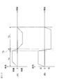
- FIG. 12 is a time chart showing an example of a running motion plan for parking support by the parking support device of the present embodiment, (A) shows a time chart of vehicle speed, and (B) shows a time chart of steering angle. show.
- FIG. 11 is a time chart showing a running motion plan for parking assistance according to a comparative example of the present invention, (A) shows a time chart of vehicle speed, and (B) shows a time chart of steering angle.
- FIG. 12 is a time chart showing an example of a running motion plan for parking support by the parking support device of the present embodiment, (A) shows a time chart of vehicle speed, and (B) shows a
- FIG. 13 is a time chart showing another example of a running motion plan for parking support by the parking support device of the present embodiment, (A) shows a time chart of vehicle speed, and (B) is a time of steering angle. Show the chart.
- FIG. 14 is a flowchart showing an example of the control procedure of the parking support device of the present embodiment of FIG.
- FIG. 15 is a flowchart showing an example of the subroutine of step S6 of the flowchart shown in FIG.
- FIG. 1 is a block diagram showing a configuration of a parking support system 1000 according to an embodiment of the present invention.
- the parking support system 1000 of the present embodiment is a system for supporting a running operation for moving (parking) the own vehicle from the current position to the parking space.
- the parking support system 1000 of the present embodiment includes a parking support device 1, an image pickup device 2, an image processing device 3, a distance measuring device 4, a vehicle controller 5, a drive system 6, a vehicle speed sensor 7, and a steering angle. It includes a sensor 8.
- CAN Control Area Network
- the parking support device 1 of the present embodiment includes a control device 11 and an output device 12.
- the control device 11 of the present embodiment is accessible to a ROM 111 which is a ROM (Read Only Memory) in which a parking support program is stored and a CPU 112 which is a CPU (Central Processing Unit) which executes a program stored in the ROM 111. It includes a RAM 113 which is a RAM (Random Access Memory) that functions as a storage device.
- the output device 12 includes a display 121 which is a display device for presenting information such as a space in which the own vehicle can be parked to the driver.
- the parking support program stored in the ROM 111 of the present embodiment detects a parking space in which the own vehicle can park, presents the parking space on the display 121, and parks the own vehicle in the parking space set by the driver. It is a program that calculates a parking route and executes a control procedure that supports an operation for moving the own vehicle from the current position to the parking space.
- the parking support device 1 of the present embodiment manually performs at least one of automatic parking, steering, accelerator, and brake for automatically parking by automatically operating the steering, accelerator, and brake, and the rest. It can also be applied to semi-automatic parking, in which the operation of is automatically parked. Further, the parking support device 1 of the present embodiment can also be applied to parking support in which the driver is presented with a parking route and the driver operates the steering, accelerator, and brake to park the own vehicle in the parking space. Is. In the present embodiment, in the case of automatic parking and semi-automatic parking, an automatic return type switch such as a deadman switch is used. In the parking support device 1, when the deadman switch is pressed, the automatic driving of the own vehicle is executed, and when the pressing of the deadman switch is released, the automatic driving and the semi-automatic driving of the own vehicle are stopped.
- an automatic return type switch such as a deadman switch
- the parking support device 1 of the present embodiment is transmitted from a portable terminal device (smartphone, PDA, intelligent key for locking / unlocking the vehicle door) capable of exchanging information with the parking support device 1. It may be activated by a signal.
- the parking support device 1 of the present embodiment can also be applied to remote parking in which the driver operates and parks his / her own vehicle from outside the vehicle.
- the image pickup device 2 of the present embodiment, the image processing device 3 of the present embodiment, and the distance measuring device 4 of the present embodiment are located around the own vehicle, such as the front, side, and the entire circumference of the own vehicle. It is a device for detecting information on the driving environment including the presence of obstacles and other conditions around the own vehicle.
- the image pickup device 2 of the present embodiment is an in-vehicle device for recognizing environmental information around the own vehicle from images.
- the imaging device 2 of the present embodiment acquires environmental information around the own vehicle by taking an image of the surroundings of the own vehicle and acquiring image data including obstacles existing around the own vehicle.
- the image pickup device 2 includes a camera including an image pickup device such as a CCD, an ultrasonic camera, an infrared camera, and other cameras.
- the environmental information around the own vehicle acquired by the image pickup device 2 is output to the control device 11.
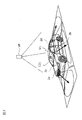
- FIG. 2 is a perspective view of the own vehicle V1 showing an example of the arrangement of the image pickup device 2 of the present embodiment mounted on the own vehicle V1.
- the image pickup device 2a is arranged on the front grille portion of the own vehicle V1
- the image pickup device 2b is arranged under the left door mirror
- the image pickup device 2c is arranged under the right door mirror
- the image pickup is performed in the vicinity of the rear bumper.
- the device 2d is arranged.
- the image pickup devices 2a to 2d may be cameras provided with a wide-angle lens having a large viewing angle. As shown in FIG.
- the image pickup device 2a images from the right front to the left front of the own vehicle V1
- the image pickup device 2b takes an image from the left front to the left rear of the own vehicle V1
- the image pickup device 2c takes an image.
- the image is taken from the left rear to the right rear of the own vehicle V1
- the image pickup device 2d images the image from the right rear to the right front of the own vehicle V1.
- the image processing device 3 of the present embodiment is a device for generating a bird's-eye view image showing the surrounding situation of the own vehicle V1 when the own vehicle V1 is viewed from an upper virtual viewpoint.
- the virtual viewpoint is, for example, the virtual viewpoint VP shown in FIG.
- the image processing device 3 generates a bird's-eye view image using a plurality of captured images acquired by using the image pickup device 2.
- the image processing performed to generate the bird's-eye view image in the image processing device 3 is not particularly limited. 116-07 (2007-10), 17-22. ”.
- the bird's-eye view image generated by the image processing device 3 is output to the control device 11 and presented to the driver by the display 121 shown in FIG.
- the display 121 shown in FIG. 2 is arranged between the driver's seat and the passenger seat at the upper part of the dashboard, but the installation position of the display 121 is not particularly limited and can be installed at an appropriate position.
- FIG. 3 is a display image showing an example of a bird's-eye view image generated by the image processing device 3 of the present embodiment.
- the traveling scene of the own vehicle V1 in FIG. 3 is a scene in which the own vehicle V1 is traveling in the parking lot in order to find the parking space PS.
- the bird's-eye view image IM1 generated by the image processing device 3 of the present embodiment is displayed on the left side of the display image shown in FIG. 3, and the monitoring image IM2 for monitoring the surroundings of the own vehicle V1 is displayed on the right side. Is displayed.
- the own vehicle V1 is displayed at the center of the bird's-eye view image IM1, and parking areas separated by white lines are displayed on the left and right sides of the own vehicle V1.
- the other vehicle V2 is displayed in the area where the other vehicle V2 is detected, and the own vehicle is displayed in the area where the own vehicle V1 can park, where no obstacles such as the other vehicle V2 are detected.
- a broken line frame indicating the parking space PS is displayed.
- the surveillance image IM2 displays an image acquired from the image pickup device 2a arranged on the front grille of the own vehicle V1 in order to present information on the surrounding environment in front of the own vehicle V1 in the current traveling direction. ..
- an obstacle such as another vehicle V2 is displayed.
- the distance measuring device 4 of the present embodiment is a device for calculating the relative distance and the relative speed between the own vehicle V1 and the object.
- the ranging device 4 is, for example, a laser radar, a millimeter wave radar or the like (LRF or the like), a LiDAR (light detection and ranking) unit, a radar device such as an ultrasonic radar, or a sonar.
- the ranging device 4 detects the presence / absence of an object, the position of the object, and the distance to the object based on the received signal of the radar device or sonar.
- the objects are, for example, obstacles, pedestrians, and other vehicles around the own vehicle V1.
- the information of the object detected by the distance measuring device 4 is output to the control device 11.
- the control device 11 of the present embodiment stops the own vehicle V1 and causes the object and the own vehicle V1 to collide with each other.
- the display 121 notifies the driver that a collision is likely to occur.
- FIG. 4 is a plan view of the own vehicle V1 showing an example of the arrangement of the distance measuring device 4 when the distance measuring device 4 of the present embodiment is mounted on the own vehicle V1.
- the own vehicle V1 shown in FIG. 4 includes a front ranging device 4a for detecting an object in front of the own vehicle V1, a lateral ranging device 4b for detecting an object on the right and left sides of the own vehicle V1. And a rear ranging device 4c for detecting an object behind the own vehicle V1.
- the own vehicle V1 shown in FIG. 4 is provided with ranging devices 4a-1 to 4a-4 as front ranging devices 4a, and ranging devices 4b-1 to 4b-4 as lateral ranging devices 4b, and is provided with rear ranging devices 4b-1 to 4b-4.
- the distance measuring devices 4c-1 to 4c-4 are provided.
- the distance measuring device 4 of the present embodiment can be installed, for example, in the bumper of the own vehicle V1. By arranging the distance measuring device 4 in this way, it is possible to prevent the calculation of the relative distance and the relative speed of the own vehicle V1 from the surrounding objects from becoming inaccurate.
- the vehicle controller 5 of the present embodiment is an in-vehicle computer such as an electronic control unit (ECU: Electronic Control Unit) for electronically controlling the drive system 6 that controls the operation of the own vehicle V1.
- the vehicle controller 5 controls a drive device, a braking device, and a steering device included in the drive system 6 to support a traveling operation for moving (parking) the own vehicle V1 from the current position to the parking space PS.
- the vehicle controller 5 receives a control command from the parking support device 1 based on the parking route, the target vehicle speed, and the target steering angle calculated in advance. The parking route, target vehicle speed, and target steering angle will be described later.
- the drive system 6 of the present embodiment includes an electric motor and / or an internal combustion engine as a traveling drive source, a power transmission device including a drive shaft and an automatic transmission for transmitting the output from these traveling drive sources to the drive wheels, and a power transmission device. It includes a driving device for controlling the wheels, a braking device for braking the wheels, and a steering device for controlling the total steering wheel according to the steering angle of the steering wheel (so-called steering wheel).
- the vehicle controller 5 receives a control command based on the parking route and the target vehicle speed calculated in advance from the parking support device 1.
- the vehicle controller 5 generates a control signal to the drive device of the drive system 6 based on the control command from the parking support device 1, and executes control of the driving behavior including acceleration / deceleration of the vehicle.
- the drive system 6 can autonomously control the vehicle speed of the own vehicle V1 by receiving the control signal from the vehicle controller 5.
- the drive system 6 of the present embodiment includes a steering device.
- the steering device includes a steering actuator, and the steering actuator includes a motor and the like attached to a column shaft of the steering.
- the steering device of the drive system 6 is controlled by the vehicle controller 5 so as to travel while maintaining a predetermined lateral position (position in the left-right direction of the vehicle) of the own vehicle with respect to the parking route calculated in advance.
- the vehicle controller 5 includes environmental information around the own vehicle V1 acquired by the image pickup device 2, a bird's-eye view image IM1 generated by the image processing device 3, and obstacles around the own vehicle V1 detected by the distance measuring device 4.
- the steering device is controlled by using at least one of the information of pedestrians and other vehicles.
- the parking support device 1 transmits a control command based on the parking route and the target steering angle calculated in advance to the vehicle controller 5. Then, the vehicle controller 5 generates a control signal to the steering device of the drive system 6 based on the control command from the parking support device 1, and executes the steering control of the own vehicle V1.
- the drive system 6 can autonomously control the steering of the own vehicle V1 by receiving the control signal from the vehicle controller 5.
- the vehicle speed sensor 7 of the present embodiment is a sensor provided in the drive device of the drive system 6 for detecting the vehicle speed of the own vehicle V1.
- the steering angle sensor 8 of the present embodiment is a sensor provided in the steering device of the drive system 6 for detecting the steering angle of the own vehicle V1.
- the vehicle speed of the own vehicle V1 detected by the vehicle speed sensor 7 and the steering angle of the own vehicle V1 detected by the steering angle sensor 8 are output to the control device 11 via the vehicle controller 5.
- the control device 11 of the present embodiment has an environment information acquisition function for acquiring environmental information around the own vehicle V1 by executing a parking support program stored in the ROM 111 by the CPU 112, and parking in which the own vehicle V1 can park.
- a parking space detection function that detects an area
- a parking space display function that displays the detected parking space PS as a bird's-eye view image IM1 on the display 121
- a parking route calculation function for calculating a parking route and a traveling operation planning function for planning a traveling operation for the own vehicle V1 to park along the calculated parking route are realized.
- the environmental information acquisition function of the control device 11 of the present embodiment is a function for the control device 11 to acquire information on the surrounding environment including the existence of obstacles located in the vicinity of the own vehicle V1.
- the control device 11 uses the environment information acquisition function to, for example, use the vehicle speed information of the own vehicle V1 detected by the vehicle speed sensor 7 and the steering angle information of the own vehicle V1 detected by the steering angle sensor 8 as information on the surrounding environment. get.
- the control device 11 has an environmental information acquisition function, for example, a vehicle position detection device (not shown) equipped with a GPS unit, a gyro sensor, and the like, and the positions of various facilities and specific points stored in the ROM.
- the position information of the own vehicle V1 detected by the three-dimensional high-precision map information including the information is acquired as information on the surrounding environment.
- the control device 11 of the present embodiment uses the information on the surrounding environment to determine whether or not the traveling scene of the own vehicle V1 is a scene in which the own vehicle V1 is parked in the parking space PS by the environmental information acquisition function. do.
- the control device 11 of the present embodiment parks the own vehicle V1 in the parking space PS. Judge that it is a scene.
- the control device 11 of the present embodiment is the own vehicle V1. Is determined to be a scene of parking in the parking space PS.
- the control device 11 of the present embodiment uses a communication device (not shown) to communicate with the outside of the vehicle (so-called road-to-vehicle communication) or from information on the surrounding environment acquired by vehicle-to-vehicle communication. It may be determined that the vehicle V1 is parked in the parking space PS. When it is determined that the vehicle V1 is parked in the parking space PS, the control device 11 of the present embodiment continues to execute the parking support program. On the other hand, for example, when it is determined from the information about the surrounding environment that the own vehicle V1 has left the parking lot and is traveling on the road, the control device 11 of the present embodiment parks the own vehicle V1. It is determined that the scene is not parked in the space PS. When it is determined that the vehicle V1 is not parked in the parking space PS, the control device 11 of the present embodiment stops the execution of the parking support program.
- a communication device not shown to communicate with the outside of the vehicle (so-called road-to-vehicle communication) or from information on the surrounding environment acquired by vehicle
- the control device 11 of the present embodiment takes an image by the environmental information acquisition function, for example, by the image pickup devices 2 attached to a plurality of places of the own vehicle V1.
- the captured image of the boundary line such as the white line around the own vehicle V1 and the objects existing in the surroundings is acquired as information on the surrounding environment.
- the control device 11 of the present embodiment acquires, for example, the detection results of the front ranging device 4a, the side ranging device 4b, and the rear ranging device 4c as information on the surrounding environment by the environment information acquisition function. ..
- the control device 11 of the present embodiment detects the parking space PS, which is a parking area in which the own vehicle V1 can park.
- the parking space detection function is used to detect the parking space PS.
- the parking space detection function of the control device 11 of the present embodiment is a function for detecting a parking area in which the own vehicle V1 can park by using the environmental information around the own vehicle V1 acquired by the environmental information acquisition function. ..
- the control device 11 of the present embodiment creates a bird's-eye view image IM1 by the image processing device 3 using the captured image acquired by the image pickup device 2 by the parking space detection function.
- the control device 11 of the present embodiment detects a line defining the boundary of the area from the created bird's-eye view image IM1 by the parking space detection function, and identifies a candidate line defining the parking area from the detected line.
- control device 11 of the present embodiment determines whether or not the specified line candidate defines the parking area by the parking space detection function, and determines that the specified line candidate defines the parking area. In this case, it is determined whether or not the own vehicle V1 can be parked in the detected parking area.
- the control device 11 of the present embodiment performs edge detection on the bird's-eye view image IM1 by the parking space detection function and calculates the brightness difference (contrast). do. Then, the control device 11 of the present embodiment identifies a pixel sequence having a brightness difference of a predetermined value or more from the bird's-eye view image IM1 by the parking space detection function, and calculates the line thickness and the line length.
- the color of the detected line does not necessarily have to be white, and may be red, yellow or other colors.
- the control device 11 of the present embodiment uses a known image processing technique such as pattern matching.
- the pattern used for pattern matching is stored in advance in the ROM 111 of the control device 11 of the present embodiment.
- FIG. 5A shows a scene in which the own vehicle V1 is about to park in the parking space PS1 which is a parking area where the own vehicle V1 can park, which is located between the other vehicle V2a and the other vehicle V2b.
- the lines defining the parking area corresponding to the parking space PS1 are the lines L1, the line L2, and the line L3, which are three of the sides forming the rectangle of the parking space PS1.
- the ROM 111 of the control device 11 of the present embodiment stores the combination of the line L1, the line L2, and the line L3 defining the parking area as a pattern corresponding to the scene of FIG. 5 (A).
- FIG. 5B shows a scene in which the own vehicle V1 is trying to parallel park in the parking space PS2 between the other vehicle V2c and the other vehicle V2d.
- the control device 11 of the present embodiment detects the line L4 as a line defining the parking area corresponding to the parking space PS2, and the image pickup device 2 detects the line L4 on the left side of the other vehicle V2c and the other vehicle V2d. Further detect curbs or walls (not shown) located in.
- the control device 11 of the present embodiment cannot define the parking area between the line L4 and the curb. Therefore, in the scene of FIG.
- the control device 11 of the present embodiment arranges the virtual line L5 behind the other vehicle V2c and the virtual line L6 in front of the other vehicle V2d. Then, when the line L4 detected by the image pickup apparatus 2 can define the parking area by the virtual lines L5 and L6, it is determined that the line L4 is the line defining the parking area.
- the ROM 111 of the control device 11 of the present embodiment shows a combination of the line L4, the virtual line L5 arranged behind the other vehicle V2c, and the virtual line L6 arranged in front of the other vehicle V2d. It is stored as a pattern corresponding to the scene of B).
- FIG. 5C shows a scene in which the own vehicle V1 is diagonally trying to park in the parking space PS3, which is a parking area where the own vehicle V1 can be parked, between the other vehicle V2e and the other vehicle V2f. ..
- the lines defining the parking area corresponding to the parking space PS3 are the lines L7, L8, L9, and L10, which are the sides forming the rectangle of the parking space PS3.
- the ROM 111 of the control device 11 of the present embodiment stores the combination of the line L7, the line L8, the line L9, and the line L10 that define the parking area as a pattern corresponding to the scene of FIG. 5C.
- the control device 11 of the present embodiment determines whether or not the control device 11 of the present embodiment has a candidate around the line specified as the line defining the parking area, which is more likely to correspond to the line defining the parking area than the specified line. Is detected. For example, when a line having a larger luminance difference is newly specified, the newly specified line is detected as a candidate for a line defining a parking area. On the other hand, when there is no candidate who is more likely to correspond to the line defining the parking area than the specified line, it is determined whether or not the specified line defines the parking area.
- the control device 11 of the present embodiment determines whether or not the specified candidate satisfies a predetermined condition.
- the predetermined conditions are, for example, (1) a length corresponding to a preset first line length distance threshold (for example, 15 [m] in the actual distance) in the line specified as a line candidate defining the parking area.
- S Does not include lines with a length longer than
- a preset first line-to-line distance range for example, in actual distance
- a preset second line length distance threshold for example, a length corresponding to 7 [m] in actual distance.
- a preset second line-to-line distance range for example, actual.
- a preset third line length distance threshold for example, 15 [m] in actual distance. It does not include a set of lines having a length greater than (corresponding length). If any one of the conditions (1), (2), or (3) is not satisfied, the control device 11 of the present embodiment determines that the specified line candidate does not define the parking area. do. On the other hand, when all the conditions (1) to (3) are satisfied, the control device 11 of the present embodiment determines that the specified line candidate defines the parking area and detects the parking area. ..
- the control device 11 of the present embodiment uses the information of the object detected by the distance measuring device 4 in the parking area. Determine if there is an obstacle in. For example, in the scene of FIG. 5A, it is determined whether or not there is an obstacle in the parking area by using the rear ranging device 4c of the own vehicle V1. Further, in the scene of FIG. 5B, it is determined whether or not there is an obstacle in the parking area by using the side distance measuring device 4b and the rear distance measuring device 4c of the own vehicle V1. Further, in the scene of FIG.
- the control device 11 of the present embodiment detects the parking area in which no obstacle exists as the parking space PS among the detected parking areas. On the other hand, the control device 11 of the present embodiment does not detect the detected parking area as the parking space PS when an obstacle exists in the detected parking area.
- the control device 11 of the present embodiment may determine whether or not the own vehicle V1 can park in the detected parking area by automatic driving. For example, if the parking area faces the wall side and the width of the passage required to control the driving operation of the autonomous driving cannot be secured, or if the parking area is surrounded by the pillars of the building, the driving operation of the autonomous driving If the information required to control the vehicle cannot be detected, the detected parking area does not correspond to a parking area that can be parked by automatic driving. Then, when the control device 11 of the present embodiment determines that there is no obstacle in the detected parking area and parking is possible by automatic operation, the detected parking area is detected as the parking space PS. On the other hand, the control device 11 of the present embodiment does not detect the detected parking area as the parking space PS when it is determined that there is no obstacle in the detected parking area but parking is not possible by automatic operation. ..
- the parking area does not necessarily have to be detected in order to detect the parking space PS.
- the control device 11 of the present embodiment may detect the area as a parking space PS.
- the control device 11 of the present embodiment may detect an area in a predetermined range in which no obstacle exists, and detect the area as a parking space PS. Further, the control device 11 of the present embodiment may detect the parking space PS by using the past traveling information.
- the parking space display function of the control device 11 of the present embodiment is a function for presenting the parking space PS to the driver by displaying the parking space PS detected by the control device 11 on the display 121.
- the control device 11 of the present embodiment presents the parking space PS to the driver in a broken line frame, for example, as shown in FIG. 3, by the parking space display function.
- the driver selects the parking space PS for parking the own vehicle V1 from the parking space PS shown in FIG.
- the parking space PS is selected, for example, by touching the screen of the display 121.
- the parking route calculation function of the control device 11 of the present embodiment is a function of calculating the parking route from the current position to the parking space PS in order for the own vehicle V1 to park in the selected parking space PS.
- the control device 11 of the present embodiment sets the turning position for the own vehicle V1 to make a turning by the parking route calculation function when the turning is required in the middle of the parking route, and the current state of the own vehicle V1.
- a parking route from the position to the parking space PS via the turning position is generated.
- the parking route generated by the control device 11 of the present embodiment steers the own vehicle V1 when the own vehicle V1 stops at the turning position based on the steering direction of the own vehicle V1 in the route from the turning position to the parking space.
- the route is such that the direction is the steering direction.
- the control device 11 according to the comparative example of the present invention is parked as shown in the plan view of FIG. Calculate the route. That is, the control device 11 according to the comparative example of the present invention detects the width W of the passage and the other vehicle V2 by the image pickup device 2 and the distance measuring device 4, and moves from the current position to the parking space PS via the turning position P. Therefore, the width W1 of the passage through which the own vehicle V1 can travel is calculated.
- the control device 11 sets the number of times of turning back, sets the turning back position P, and calculates a parking route for moving from the current position to the parking space PS via the turning back position P.
- the parking route shown in FIG. 6 is a section ZA in which the own vehicle V1 moves from the current position to the turning position P at a constant steering angle, and a section in which the own vehicle V1 moves from the turning position P to the parking space PS. Includes section ZB.
- the own vehicle V1 makes a stationary cut at the turning position P and steers the steering direction to the steering direction.
- the steering direction is steered in the steering direction while accelerating in the section ZB without making a stationary stop at the turning position. It is also possible to control various running movements. However, such a traveling operation gives a feeling of strangeness to the occupants of the own vehicle V1 because the movement of the own vehicle V1 changes significantly during acceleration. Further, in order to steer the steering direction in the steering direction, it is necessary to suppress the vehicle speed of the own vehicle V1 until the steering is completed.
- the own vehicle V1 needs to stop at the turning position P in order to change the traveling direction.
- the steering direction is not steered in the steering direction, but when the vehicle speed of the vehicle V1 is lowered to stop, the steering direction is changed to the steering direction.
- the control device 11 of the present embodiment steers the steering direction to the steering direction when the vehicle speed is lowered because the own vehicle V1 stops (in other words, before the turning position P). It suppresses the discomfort given to the occupants of the own vehicle V1, shortens the time required for steering, and shortens the time for suppressing the vehicle speed of the own vehicle V1 after turning back.
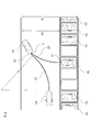
- the control device 11 of the present embodiment is shown in the plan view of FIG. 7 by the parking route calculation function.
- Calculate the parking route That is, the control device 11 of the present embodiment detects the width W of the passage and the other vehicle V2 by the image pickup device 2 and the distance measuring device 4, and moves from the current position to the parking space PS via the turning position P. The width W1 of the passage through which the own vehicle V1 can travel is calculated. Then, the control device 11 of the present embodiment sets the number of times of turning back, sets the turning back position P, and calculates the parking route for moving from the current position to the parking space PS via the turning back position P.
- the parking route shown in FIG. 7 is a section from the current position of the own vehicle V1 to the front of the turning position P, and is after the first section Z1 in which the own vehicle V1 moves at a constant steering angle and the first section Z1.
- the second section Z2, which is the section before the turning position P including the turning position P, and the section after the second section Z2, in the direction in which the own vehicle V1 moves to the parking space PS. Includes the third section Z3, which steers toward.
- the own vehicle V1 moves at a constant steering angle in the first section Z1, but in the parking route of the present embodiment, the own vehicle V1 does not necessarily move at a constant steering angle. good. Further, in the parking route of the present embodiment, the own vehicle V1 may move at a constant steering angle in the third section Z3.
- the control device 11 of the present embodiment sets the width W of the passage and the obstacles around the own vehicle V1 as, for example, the vehicle.
- the own vehicle V1 can travel only a part of the width W of the passage.
- the control device 11 of the present embodiment calculates the width of the passage through which the own vehicle V1 can travel in order to move from the current position to the parking space PS via the turning position P, which is calculated by the parking route calculation function.
- the turning position P is set using at least one of W1, the minimum turning radius of the own vehicle V1, the steering speed of the own vehicle V1, and the vehicle speed of the own vehicle V1.
- the control device 11 of the present embodiment may use the total length and the total width of the own vehicle V1.
- the width W1 of the passage through which the own vehicle V1 can travel, the minimum turning radius, the total length, and the total width of the own vehicle V1 are determined to be predetermined values depending on the traveling scene and the own vehicle V1.
- the steering speed of the own vehicle V1 and the vehicle speed of the own vehicle V1 can be set to appropriate values within a predetermined range.
- the control device 11 of the present embodiment sets the turning position P so that the time required for the own vehicle V1 to move from the current position to the parking space PS is the shortest, for example. For example, when the own vehicle V1 moves from the current position to the parking space PS, even if it can be moved by one turn, if it is determined that the movement is completed in a shorter time by moving by three turns, this implementation is carried out.
- the control device 11 of the form sets three turning positions P. Further, the control device 11 of the present embodiment may set the turning position P so that the number of times of turning required for the own vehicle V1 to move from the current position to the parking space PS is minimized. If the current position, the turning position P, and the parking space PS of the own vehicle V1 are set, the control device 11 of the present embodiment can calculate the parking route.
- the route of the second section Z2 of the present embodiment is self-directed when the own vehicle V1 stops at the turning position P based on the steering direction of the own vehicle V1 in the third section Z3 from the turning position P to the parking space PS.
- the route is such that the steering direction of the vehicle V1 is the steering direction.
- the steering direction is, for example, the direction of the steering angle of the own vehicle V1 or the direction in which the front wheels of the own vehicle V1 face the front of the own vehicle V1.
- the direction of the steering angle of the own vehicle V1 moving forward and the direction in which the front wheels of the own vehicle V1 face the front of the own vehicle V1 turn to the left. I'm steering.
- the control device 11 of the present embodiment determines that it is necessary to steer the steering direction from the left side to the right side before and after the turning position P, and when the own vehicle V1 stops at the turning position P, for example, itself.
- the route of the second section Z2 is calculated so that the direction of the steering angle of the vehicle V1 or the direction in which the front wheels of the own vehicle V1 face the front of the own vehicle V1 is on the right side.
- the route of the second section Z2 of the present embodiment may be a route such that the steering direction of the own vehicle V1 becomes the steering direction when the own vehicle V1 stops at the turning position P, but the own vehicle V1 is the turning position.
- the steering angle of the own vehicle V1 when stopped at P is set to be equal to the steering angle when the own vehicle V1 starts traveling from the turning position P toward the parking space PS in the third section. May be good. As a result, it is not necessary to change the steering direction when accelerating from the state where the own vehicle V1 is stopped, so that it is not necessary to suppress the vehicle speed of the own vehicle V1 until the steering is completed.
- control device 11 of the present embodiment can expand and contract the distance of the second section Z2 according to the width W1 of the passage in which the own vehicle V1 can travel.
- the traveling scene shown in FIG. 8 is the same as the traveling scene shown in FIG. 7, but the width W1 of the passage through which the own vehicle V1 can travel is narrower than that in FIG. 7.
- the control device 11 of the present embodiment uses the parking route calculation function to make the distance of the second section Z2 shorter than the distance of the second section Z2 shown in FIG. 7, and the parking route shown in the plan view of FIG. Is calculated.
- the distance of the second section Z2 shown in FIG. 8 can be expanded and contracted by changing the steering speed of the own vehicle V1 and / or the vehicle speed of the own vehicle V1.
- the distance of the second section Z2 when the distance of the second section Z2 is shortened, the steering speed of the own vehicle V1 is increased and / or the vehicle speed of the own vehicle V1 is decreased. On the other hand, when the distance of the second section Z2 is increased, the steering speed of the own vehicle V1 is decreased and / or the vehicle speed of the own vehicle V1 is increased. Further, the distance of the second section Z2 may be shortened in advance and extended during the parking support, or the distance may be increased or decreased during the control of the parking support.
- the route of the second section Z2 of the present embodiment can be set every time the own vehicle V1 turns back.
- the traveling scenes shown in FIGS. 9A to 9D are the same as the traveling scenes shown in FIGS. 7 and 8, but the width W1 of the passage through which the own vehicle V1 can travel is narrower than that in FIG.
- the control device 11 of the present embodiment sets three turning positions Pa to Pc by the parking route calculation function in order to move the own vehicle V1 from the current position to the parking space PS, and the first time. After the second turn, the route of the second section Z2 of the present embodiment is calculated.
- the control device 11 of the present embodiment detects the width W of the passage and the other vehicle V2 by the image pickup device 2 and the distance measuring device 4, and parks from the current position via the turning position P.
- the width W1 of the passage through which the own vehicle V1 can travel in order to move to the space PS is calculated.
- the control device 11 of the present embodiment sets the second turning position Pb shown in FIG. 9B after setting the first turning position Pa. In the second turning, the own vehicle V1 moves backward to the turning position Pb.
- the control device 11 of the present embodiment calculates the width W of the passage as the width W2 of the passage through which the own vehicle can travel. Further, the control device 11 of the present embodiment sets the third turning position Pc shown in FIG. 9C after setting the second turning position Pb. Similar to the second turn, the other vehicle V2, which is an obstacle, is not detected even in the third turn. Therefore, the control device 11 of the present embodiment calculates the width W of the passage as the width W2 of the passage through which the own vehicle can travel. do. Then, the control device 11 of the present embodiment calculates a parking route in which the own vehicle V1 moves from the current position to the parking space PS via the turning positions Pa, Pb, and Pc.
- the control device 11 of the present embodiment calculates the parking route in which the own vehicle V1 moves from the current position to the turning position Pa, as shown in FIG. 9A.
- the parking route shown in FIG. 9A includes a first section Z1a and a second section Z2a.
- the steering direction of the own vehicle V1 is changed when the own vehicle V1 stops at the turning position Pa based on the steering direction of the own vehicle V1 when going from the turning position Pa to the turning position Pb. It is a route that is in the rudder direction.
- control device 11 of the present embodiment determines that it is necessary to steer the steering direction from the left side to the right side before and after the turning position Pa, and when the own vehicle V1 stops at the turning position Pa, for example, itself.
- the route of the second section Z2a is calculated so that the direction of the steering angle of the vehicle V1 or the direction in which the front wheels of the own vehicle V1 face the front of the own vehicle V1 is on the right side.
- the control device 11 of the present embodiment calculates the parking route in which the own vehicle V1 moves from the turning position Pa to the turning position Pb shown in FIG. 9B.
- the parking route shown in FIG. 9B includes a first section Z1b and a second section Z2b.
- the steering direction of the own vehicle V1 is changed when the own vehicle V1 stops at the turning position Pb based on the steering direction of the own vehicle V1 when going from the turning position Pb to the turning position Pc. It is a route that is in the rudder direction.
- control device 11 of the present embodiment determines that it is necessary to steer the steering direction from the right side to the left side before and after the turning position Pb, and when the own vehicle V1 stops at the turning position Pb, for example, itself.
- the route of the second section Z2b is calculated so that the direction of the steering angle of the vehicle V1 or the direction in which the front wheels of the own vehicle V1 face the front of the own vehicle V1 is on the left side.
- the control device 11 of the present embodiment calculates the parking route in which the own vehicle V1 moves from the turning position Pb to the turning position Pc shown in FIG. 9C.
- the parking route shown in FIG. 9C comprises the first section Z1c.
- the own vehicle V1 can move from the turning position Pb to the turning position Pc at a constant steering angle, and it is not necessary to steer at the turning position Pc. Therefore, it is not necessary to set the second section Z2 of the present embodiment.
- the control device 11 of the present embodiment calculates a parking route in which the own vehicle V1 moves backward and straight from the turning position Pc to the parking space PS, as shown in FIG. 9D.
- the parking route shown in FIG. 9D comprises a third section Z3.
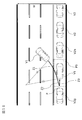
- control device 11 of the present embodiment can provide parking support even in parallel parking.
- the control device 11 of the present embodiment parallelizes the parking route by the parking route calculation function. calculate. That is, the control device 11 of the present embodiment detects the width W of the passage and the other vehicles V2g and V2h by the image pickup device 2 and the distance measuring device 4, and moves from the current position to the parking space PS via the turning position P. Therefore, the width W1 of the passage through which the own vehicle V1 can travel is calculated. In FIG. 10, the width W1 of the passage through which the own vehicle V1 can travel is equal to the detected width W of the passage.
- the control device 11 of the present embodiment sets the number of times of turning back, sets the turning back position P, and calculates the parking route in which the own vehicle V1 moves from the current position to the parking space PS via the turning back position P. ..
- the control device 11 of the present embodiment sets one turning position P.
- the control device 11 of the present embodiment calculates a parking route in which the own vehicle V1 moves from the current position to the parking space PS via the turning position P.
- the parallel parking parking route shown in FIG. 10 includes a first section Z1, a second section Z2, and a third section Z3.
- the steering direction of the own vehicle V1 is steered from the left side to the right side before and after the turning position P. Therefore, when the own vehicle V1 stops at the turning position P, the steering direction of the own vehicle V1 is steered to the right side.
- the route of the second section Z2 is calculated so as to be performed.
- the traveling operation planning function of the control device 11 of the present embodiment is a function of planning a traveling operation for the own vehicle V1 to park in the parking space PS along the parking route calculated by the parking route calculation function.
- the control device 11 of the present embodiment plans to control the vehicle speed and the steering angle of the own vehicle V1 so that the own vehicle V1 moves to the parking space PS along the parking route by the traveling motion planning function.
- FIG. 11 is a time chart showing a traveling operation plan when the own vehicle V1 moves from the current position to the parking space PS along the parking route according to the comparative example of the present invention as shown in FIG. 6, for example.
- FIG. 11A shows a time chart of vehicle speed
- FIG. 11B shows a time chart of steering angle.
- the horizontal axis of FIG. 11A represents time
- the vertical axis represents vehicle speed.
- the horizontal axis of FIG. 11B represents time and corresponds to the horizontal axis of FIG. 11A.
- the vertical axis of FIG. 11B represents the steering angle, and when the value is positive, the own vehicle V1 steers to the left, and when the value is negative, the own vehicle V1 steers to the right.
- the parking route shown in FIG. 6 includes a section ZA in which the own vehicle V1 moves from the current position to the turning position P, a turning position P in which the own vehicle V1 makes a stationary cut, and a parking space in which the own vehicle V1 moves from the turning position P.
- the vehicle speed and steering angle in section TA, the vehicle speed and steering angle in section TB, and the vehicle speed and steering angle in section TC shown in FIG. 11 are the traveling operations of the own vehicle V1 in section ZA, respectively. It corresponds to the stationary operation of the own vehicle V1 at the turning position P and the traveling operation of the own vehicle V1 in the section ZB.
- the stationary steering is performed in the section TB, the own vehicle V1 is stopped while the steering direction is steered in the steering direction. Therefore, it takes time to complete the running operation. Further, the stationary steering operation causes the tires to wear and the steering actuator to generate heat, which imposes a burden on the own vehicle V1.
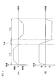
- control device 11 of the present embodiment is, for example, the time chart of FIG. 12 when the own vehicle V1 moves from the current position to the parking space PS along the parking route of the present embodiment shown in FIG. Generate the driving operation plan shown in.
- the notation method of the vehicle speed in FIG. 12 (A) and the steering angle in FIG. 12 (B) conforms to FIGS. 11 (A) and 11 (B).
- the parking route shown in FIG. 7 includes a first section Z1, a second section Z2, and a third section Z3.
- the vehicle speed and steering angle in section T1, the vehicle speed and steering angle in section T2, and the vehicle speed and steering angle in section T3 shown in FIG. 12 are the traveling operations of the own vehicle V1 in the first section Z1 shown in FIG. 7, respectively. It corresponds to the traveling operation of the own vehicle V1 in the second section Z2 shown in 7 and the traveling operation of the own vehicle V1 in the third section Z3 shown in FIG.
- the vehicle speed becomes 0 at the turning position P, that is, the steering is performed from left to right before the own vehicle V1 stops. Therefore, the parking according to the comparative example of the present invention.
- the own vehicle V1 can quickly start retreating after stopping at the turning position P. As a result, the time required for parking can be shortened. Further, since it is not necessary to steer when accelerating in the section T3 of FIG. 12, the acceleration in the section T3 can be performed at a larger acceleration than that shown in FIG. As a result, the time required for parking can be shortened.
- control device 11 of the present embodiment travels, for example, as shown in the time chart of FIG. 13 when the own vehicle V1 moves from the current position to the parking space PS along the parking route of the present embodiment shown in FIG. Generate an operation plan.
- the notation method of the vehicle speed in FIG. 13 (A) and the steering angle in FIG. 13 (B) conforms to FIGS. 11 (A) and 11 (B).
- the parking route shown in FIG. 8 includes the first section Z1, the second section Z2, and the third section Z3, like the parking route shown in FIG. 7, but the distance of the second section Z2 shown in FIG. 8 is FIG. 7. It is shorter than the second section Z2 shown in.
- the vehicle speed and steering angle in section T4, the vehicle speed and steering angle in section T5, and the vehicle speed and steering angle in section T6 shown in FIG. 13 are the traveling operations of the own vehicle V1 in the first section Z1 shown in FIG. 8, respectively. It corresponds to the traveling operation of the own vehicle V1 in the second section Z2 shown in 8 and the traveling operation of the own vehicle V1 in the third section Z3 shown in FIG.
- the traveling motion plan shown in FIG. 13 is the same as the traveling motion plan of FIG. 12 except for the section T5.
- the own vehicle V1 is stopped at a larger acceleration than the section T2 of FIG. 12 in the section T5, and the steering is steered at a larger steering speed. conduct.
- the distance of the second section Z2 shown in FIG. 8 can be made shorter than the distance of the second section Z2 shown in FIG.
- the traveling motion plan shown in FIG. 13 since the section T5 is shorter than the section T2, the time required for parking can be shortened as compared with the traveling motion plan shown in FIG.
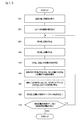
- FIG. 14 is an example of a flowchart showing the basic processing of the parking support processing of the present embodiment.
- FIG. 15 is a flowchart showing an example of the subroutine in step S6 of FIG.
- the travel control process described below is executed by the control device 11 at predetermined time intervals. Further, in the following, the control device 11 of the present embodiment will be described as determining that the vehicle V1 is a traveling scene in which the vehicle V1 is parked in the parking space PS based on the information on the surrounding environment and executes the parking support program.
- step S1 of FIG. 14 the control device 11 of the present embodiment uses the environmental information acquisition function to image the surroundings of the own vehicle using the image pickup device 2, and obtains image data including obstacles existing around the own vehicle. get. Further, in step S1, the control device 11 of the present embodiment uses the distance measuring device 4 to determine the presence / absence of obstacles, pedestrians, other vehicles, and the position of the object around the own vehicle V1 by using the environmental information acquisition function. Detect the distance to the object.
- step S2 the control device 11 of the present embodiment creates a bird's-eye view image IM1 by the image processing device 3 using the image acquired by the image pickup device 2 by the parking space detection function.
- step S3 the control device 11 of the present embodiment detects the parking area from the bird's-eye view image IM1 by the parking space detection function, and detects the parking space PS from the parking area by using the image pickup device 2 and the distance measuring device 4. ..
- step S4 the control device 11 of the present embodiment presents the parking space PS to the driver using the display 121 by the parking space display function.
- step S5 the control device 11 of the present embodiment determines whether or not the driver has selected the parking space PS for parking the own vehicle V1 from the parking space PS. If the driver has not selected the parking space PS for parking the own vehicle V1 from the parking space PS (step S5: NO), the process returns to step S4, and the control device 11 of the present embodiment sets the parking space PS. Present it to the driver. On the other hand, when the driver selects the parking space PS for parking the own vehicle V1 from the parking space PS (step S5: YES), the process proceeds to step S6.
- step S6 the control device 11 of the present embodiment calculates the parking route in which the own vehicle V1 moves from the current position to the parking space PS selected by the driver by the parking route calculation function.
- step S7 the control device 11 of the present embodiment plans a traveling operation for the own vehicle V1 to park along the calculated parking route by the traveling operation planning function.
- step S8 the control device 11 of the present embodiment uses the vehicle controller 5, the drive system 6, the vehicle speed sensor 7, and the steering angle sensor 8 according to the calculated parking route and the planned running operation. Carry out parking assistance for vehicle V1.
- step S61 of FIG. 15 the control device 11 of the present embodiment detects an obstacle such as the width W of the passage and the other vehicle V2 by using the image pickup device 2 and the distance measuring device 4 by the parking route calculation function. ..
- step S62 the control device 11 of the present embodiment calculates the widths W1 and W2 of the passage in which the own vehicle can travel by the parking route calculation function.
- step S63 the control device 11 of the present embodiment uses the parking route calculation function to determine the width W1 of the passage through which the own vehicle V1 can travel, the minimum turning radius of the own vehicle V1, the steering speed of the own vehicle V1, and the own vehicle. The number of turns is set using at least one of the vehicle speeds of V1. Further, in step S64, the control device 11 of the present embodiment sets the turn-back position P by using the set turn-back number of times by the parking route calculation function.
- step S65 the control device 11 of the present embodiment determines the steering direction at the turning position by the parking route calculation function.
- step S66 the control device 11 of the present embodiment uses the turning position P set by the parking route calculation function and the determined steering direction, and the steering direction of the own vehicle V1 becomes the steering direction. , Calculate the route from the current position to the turning position P.
- step S67 the control device 11 of the present embodiment uses the parking route calculation function to make the steering direction of the own vehicle V1 the steering direction from the turning position to the next turning position. Calculate the route of.
- step S67 is an arbitrary step and is shown by a broken line in FIG.
- step S68 the control device 11 of the present embodiment calculates the route from the turning position to the parking space by the parking route calculation function.
- step S69 the control device 11 of the present embodiment determines whether or not the parking route for the own vehicle V1 to move from the current position to the parking space PS can be calculated by the parking route calculation function. If the parking route for the own vehicle V1 to move from the current position to the parking space PS can be calculated (step S69: YES), the process proceeds to step S7 in FIG. Therefore, the traveling operation for the own vehicle V1 to park along the calculated parking route is planned. On the other hand, if the parking route on which the own vehicle V1 moves from the current position to the parking space PS cannot be calculated (step S69: NO), the process returns to step S63, and the control device 11 of the present embodiment calculates the parking route. Depending on the function, the number of cutbacks is set again.
- the parking space PS for parking the own vehicle V1 is detected, and the turning position P for the own vehicle V1 to turn back is set. It sets, generates a parking route from the current position of the own vehicle V1 to the parking space PS via the turning position P, and autonomously controls the own vehicle V1 along the parking route.
- the parking route after determining the steering direction of the own vehicle V1 in the route from the turning position P to the parking space PS, when the own vehicle V1 stops at the turning position P, the steering direction of the own vehicle V1 is changed.
- the route from the current position of the own vehicle V1 to the turning position P so as to be in the steering direction is included.
- the steering direction is steered in the steering direction, and it is possible to suppress the discomfort that the traveling operation of the own vehicle V1 gives to the occupants.
- the amount of stationary steering when the own vehicle V1 is steered can be suppressed, the time required for steering can be shortened, and the time required for parking can be shortened.
- the steering direction of the own vehicle V1 is the steering direction, so that the amount of steering after turning back can be suppressed.
- the time for suppressing the vehicle speed of the own vehicle V1 after turning back can be shortened, and the time required for parking can be shortened.
- the steering angle of the own vehicle V1 when the own vehicle V1 stops at the turning position P is set from the turning position P toward the parking space PS.
- the angle is set to be equal to the steering angle when the own vehicle V1 starts traveling.
- the parking route is a section from the current position of the own vehicle V1 to the front of the turning position P, and the own vehicle has a constant steering angle.
- the parking support device 1 and the parking support method according to the present embodiment when the passage width W1 that can be traveled to move from the current position of the own vehicle V1 to the parking space PS via the turning position P is narrow, The distance of the second section Z2 is relatively shortened as compared with the case where the passage width W1 is wide. As a result, even when the passage width W1 is narrow, the amount of stationary steering when the own vehicle V1 is steered can be suppressed, the time required for steering can be shortened, and the time required for parking can be shortened. .. Further, even when the passage width W1 is narrow, the amount of steering after turning back can be suppressed, the time for suppressing the vehicle speed of the own vehicle V1 can be shortened, and the time required for parking can be shortened.
- a predetermined passage width W1 that can be traveled to move from the current position of the own vehicle V1 to the parking space PS via the turning position P is predetermined.
- the distance of the second section Z2 is relatively shortened as compared with the case where the passage width W1 is equal to or more than the predetermined value.
- the predetermined value of the passage width W1 to be determined in advance can be appropriately set by using the minimum turning radius, the total length, the total width, and the like of the own vehicle V1.
- the distance between the two sections Z2 is shortened.
- the steering speed of the own vehicle V1 is relatively increased and / or , The vehicle speed of the own vehicle V1 is relatively reduced.
- the passage width W1 is narrow, the amount of stationary steering when the own vehicle V1 is steered can be suppressed, the time required for steering can be shortened, and the time required for parking can be shortened. ..
- the amount of steering after turning back can be suppressed, the time for suppressing the vehicle speed of the own vehicle V1 can be shortened, and the time required for parking can be shortened.
- a predetermined passage width W1 that can be traveled to move from the current position of the own vehicle V1 to the parking space PS via the turning position P is predetermined. If it is less than the value, the steering speed of the own vehicle V1 is relatively increased and / or the vehicle speed of the own vehicle V1 is relatively decreased. As a result, even when the passage width W1 is narrow, the amount of stationary steering when the own vehicle V1 is steered can be suppressed, the time required for steering can be shortened, and the time required for parking can be shortened. .. Further, even when the passage width W1 is narrow, the amount of steering after turning back can be suppressed, the time for suppressing the vehicle speed of the own vehicle V1 can be shortened, and the time required for parking can be shortened.
- the narrower the passage width W1 that can be traveled to move from the current position of the own vehicle V1 to the parking space PS via the turning position P the more the self The steering speed of the vehicle V1 is increased and / or the vehicle speed of the own vehicle V1 is relatively decreased.
- the passage width W1 is narrow, the amount of stationary steering when the own vehicle V1 is steered can be suppressed, the time required for steering can be shortened, and the time required for parking can be shortened. ..
- the passage width W1 is narrow, the amount of steering after turning back can be suppressed, the time for suppressing the vehicle speed of the own vehicle V1 can be shortened, and the time required for parking can be shortened.
- the distance of the second section Z2 is at least the passage width W1, the minimum turning radius of the own vehicle V1, and the steering speed of the own vehicle V1. , Set using the vehicle speed of the own vehicle V1. Thereby, in order to shorten the time required for steering and shorten the time required for parking, a more appropriate distance of the second section Z2 can be calculated.
- Sections T3, T6 Sections corresponding to the third section ZA ... Sections where the own vehicle moves from the current position to the turning position P at a constant steering angle ZB ...
- the own vehicle V1 moves from the turning position P to the parking space.
Abstract
Provided are a parking assist method and a parking assist device (1) with which the time required for parking can be shortened when parking assistance is performed for a vehicle on a route that includes a direction reversal. The present invention detects a parking space (PS) for parking a host vehicle (V1), sets a reverse-direction position (P) for the host vehicle (V1) to reverse directions, generates a parking route leading from the present position of the host vehicle (V1) to the parking space (PS) via the reverse-direction position (P), and controls the autonomous travel of the host vehicle (V1) along the parking route. In the present invention, when the parking route is generated, the turning direction of the host vehicle (V1) in the route from the reverse-direction position (P) to the parking space (PS) is determined, and when the host vehicle (V1) has stopped at the reverse-direction position (P), a route from the present position of the host vehicle (V1) to the reverse-direction position (P) is generated so that the steering direction of the host vehicle (V1) will be the turning direction.
Description
本発明は、駐車支援方法及び駐車支援装置に関するものである。
The present invention relates to a parking support method and a parking support device.
車両の縦列駐車支援時に、車両が入庫する間口の駐車スペース長が、車両の全長と所定長の和以上であるか否かを判断し、前記駐車スペース長が車両の全長と所定長の和以上である場合には、据え切りの無いクロソイド曲線の経路で車両の駐車支援を行い、前記駐車スペース長が車両の全長と所定長の和未満である場合には、据え切り有りの経路で車両の駐車支援を行う駐車支援方法が知られている(特許文献1)。
When supporting parallel parking of a vehicle, it is determined whether or not the parking space length at the frontage of the vehicle is equal to or greater than the sum of the total length of the vehicle and the predetermined length, and the parking space length is equal to or greater than the sum of the total length of the vehicle and the predetermined length. If the parking space length is less than the sum of the total length of the vehicle and the predetermined length, the vehicle is parked on the route with a parallel parking. A parking support method for providing parking support is known (Patent Document 1).
上記従来技術は、切り返しを含む経路で車両の駐車支援を行う場合に、切り返し後に、自車両の操舵方向がそれまでとは逆方向になるため、駐車に要する時間が長くなるという問題がある。
The above-mentioned conventional technique has a problem that when parking assistance of a vehicle is performed on a route including turning back, the steering direction of the own vehicle becomes the opposite direction after turning back, so that the time required for parking becomes long.
本発明が解決しようとする課題は、切り返しを含む経路で車両の駐車支援を行う場合に、駐車に要する時間を短縮することができる駐車支援方法及び駐車支援装置を提供することである。
An object to be solved by the present invention is to provide a parking support method and a parking support device capable of shortening the time required for parking when parking support of a vehicle is performed on a route including turning back.
本発明は、切り返し位置から駐車スペースへ向かう経路における自車両の転舵方向を判定し、自車両が切り返し位置に停止したときに、自車両の操舵方向が転舵方向となるように、自車両の現在位置から切り返し位置までの経路を生成することによって上記課題を解決する。
The present invention determines the steering direction of the own vehicle on the route from the turning position to the parking space, and when the own vehicle stops at the turning position, the steering direction of the own vehicle becomes the turning direction. The above problem is solved by generating a path from the current position of the vehicle to the turning position.
本発明によれば、切り返しを含む経路で車両の駐車支援を行う場合に、駐車に要する時間を短縮することができる。
According to the present invention, it is possible to shorten the time required for parking when the vehicle parking support is provided on a route including turning back.
以下、本発明に係る一の実施形態を図面に基づいて説明する。
Hereinafter, one embodiment according to the present invention will be described with reference to the drawings.
図1は、本発明の一実施形態に係る駐車支援システム1000の構成を示すブロック図である。本実施形態の駐車支援システム1000は、自車両が現在位置から駐車スペースまで移動する(駐車する)ための走行動作を支援するためのシステムである。本実施形態の駐車支援システム1000は、駐車支援装置1と、撮像装置2と、画像処理装置3と、測距装置4と、車両コントローラ5と、駆動システム6と、車速センサ7と、操舵角センサ8とを備える。これらの各構成は、相互に情報の授受を行うためにCAN(Controller Area Network)その他の車載LANによって接続されている。
FIG. 1 is a block diagram showing a configuration of a parking support system 1000 according to an embodiment of the present invention. The parking support system 1000 of the present embodiment is a system for supporting a running operation for moving (parking) the own vehicle from the current position to the parking space. The parking support system 1000 of the present embodiment includes a parking support device 1, an image pickup device 2, an image processing device 3, a distance measuring device 4, a vehicle controller 5, a drive system 6, a vehicle speed sensor 7, and a steering angle. It includes a sensor 8. Each of these configurations is connected by a CAN (Control Area Network) or other in-vehicle LAN in order to exchange information with each other.
本実施形態の駐車支援装置1は、制御装置11と、出力装置12とを備える。本実施形態の制御装置11は、駐車支援プログラムが格納されたROM(Read Only Memory)であるROM111と、ROM111に格納されたプログラムを実行するCPU(Central Processing Unit)であるCPU112と、アクセス可能な記憶装置として機能するRAM(Random Access Memory)であるRAM113とを備える。出力装置12は、自車両が駐車可能なスペースなどの情報をドライバーに提示するための表示装置であるディスプレイ121を備える。本実施形態のROM111に格納された駐車支援プログラムは、自車両が駐車可能な駐車スペースを検出し、駐車スペースをディスプレイ121に提示し、ドライバーにより設定された駐車スペースに自車両を駐車するための駐車経路を算出し、自車両が現在位置から駐車スペースまで移動するための操作を支援する制御手順を実行させるプログラムである。
The parking support device 1 of the present embodiment includes a control device 11 and an output device 12. The control device 11 of the present embodiment is accessible to a ROM 111 which is a ROM (Read Only Memory) in which a parking support program is stored and a CPU 112 which is a CPU (Central Processing Unit) which executes a program stored in the ROM 111. It includes a RAM 113 which is a RAM (Random Access Memory) that functions as a storage device. The output device 12 includes a display 121 which is a display device for presenting information such as a space in which the own vehicle can be parked to the driver. The parking support program stored in the ROM 111 of the present embodiment detects a parking space in which the own vehicle can park, presents the parking space on the display 121, and parks the own vehicle in the parking space set by the driver. It is a program that calculates a parking route and executes a control procedure that supports an operation for moving the own vehicle from the current position to the parking space.
本実施形態の駐車支援装置1は、ステアリング、アクセル、ブレーキを全て自動で操作することにより自動で駐車させる自動駐車、ステアリング、アクセル、ブレーキのうち、少なくとも何れか1つの操作を手動で行い、残りの操作を自動で駐車させる半自動駐車にも適用可能である。また、本実施形態の駐車支援装置1は、ドライバーに駐車経路を提示して、ドライバーがステアリング、アクセル、及びブレーキを操作することで自車両を駐車スペースに駐車させるような駐車支援にも適用可能である。なお、本実施形態では、自動駐車及び半自動駐車の場合は、デッドマンスイッチなどの自動復帰型スイッチを用いる。駐車支援装置1において、デッドマンスイッチが押圧されている場合に自車両の自動運転が実行され、デッドマンスイッチの押圧が解除されると自車両の自動運転及び半自動運転が中止される。
The parking support device 1 of the present embodiment manually performs at least one of automatic parking, steering, accelerator, and brake for automatically parking by automatically operating the steering, accelerator, and brake, and the rest. It can also be applied to semi-automatic parking, in which the operation of is automatically parked. Further, the parking support device 1 of the present embodiment can also be applied to parking support in which the driver is presented with a parking route and the driver operates the steering, accelerator, and brake to park the own vehicle in the parking space. Is. In the present embodiment, in the case of automatic parking and semi-automatic parking, an automatic return type switch such as a deadman switch is used. In the parking support device 1, when the deadman switch is pressed, the automatic driving of the own vehicle is executed, and when the pressing of the deadman switch is released, the automatic driving and the semi-automatic driving of the own vehicle are stopped.
また、本実施形態の駐車支援装置1は、駐車支援装置1と情報の授受が可能な可搬の端末装置(スマートフォン、PDA、車両のドアを施解錠するインテリジェントキーなどの機器)から送信された信号により作動してもよい。この場合、本実施形態の駐車支援装置1は、ドライバーが車外から自車両を操作して駐車させるリモートパーキングにも適用可能である。
Further, the parking support device 1 of the present embodiment is transmitted from a portable terminal device (smartphone, PDA, intelligent key for locking / unlocking the vehicle door) capable of exchanging information with the parking support device 1. It may be activated by a signal. In this case, the parking support device 1 of the present embodiment can also be applied to remote parking in which the driver operates and parks his / her own vehicle from outside the vehicle.
本実施形態の撮像装置2と、本実施形態の画像処理装置3と、本実施形態の測距装置4は、自車両の前方、側方、後方の全周囲など、自車両の周囲に位置する障害物の存在を含む走行環境に関する情報、その他の自車両の周囲の状況を検出するための装置である。
The image pickup device 2 of the present embodiment, the image processing device 3 of the present embodiment, and the distance measuring device 4 of the present embodiment are located around the own vehicle, such as the front, side, and the entire circumference of the own vehicle. It is a device for detecting information on the driving environment including the presence of obstacles and other conditions around the own vehicle.
本実施形態の撮像装置2は、自車両周囲の環境情報を画像により認識するための車載装置である。本実施形態の撮像装置2は、自車両の周囲を撮像し、自車両の周囲に存在する障害物を含む画像データを取得することによって、自車両周囲の環境情報を取得する。撮像装置2は、CCD等の撮像素子を備えるカメラ、超音波カメラ、赤外線カメラその他カメラを含む。撮像装置2により取得された自車両周囲の環境情報は、制御装置11に出力される。
The image pickup device 2 of the present embodiment is an in-vehicle device for recognizing environmental information around the own vehicle from images. The imaging device 2 of the present embodiment acquires environmental information around the own vehicle by taking an image of the surroundings of the own vehicle and acquiring image data including obstacles existing around the own vehicle. The image pickup device 2 includes a camera including an image pickup device such as a CCD, an ultrasonic camera, an infrared camera, and other cameras. The environmental information around the own vehicle acquired by the image pickup device 2 is output to the control device 11.
図2は、自車両V1に搭載された本実施形態の撮像装置2の配置の一例を示す、自車両V1の斜視図である。図2に示す例では、自車両V1のフロントグリル部に撮像装置2aを配置し、左ドアミラーの下部に撮像装置2bを配置し、右ドアミラーの下部に撮像装置2cを配置し、リアバンパ近傍に撮像装置2dを配置している。撮像装置2a~2dは、視野角の大きい広角レンズを備えたカメラであってもよい。図2に示すように、撮像装置2aは、自車両V1の右前方から左前方までを撮像し、撮像装置2bは、自車両V1の左前方から左後方までを撮像し、撮像装置2cは、自車両V1の左後方から右後方までを撮像し、撮像装置2dは、自車両V1の右後方から右前方までを撮像する。このように撮像装置2を配置することで、自車両V1の周囲の環境情報を取得する場合に、情報が取得できない死角を減らすことができる。なお、撮像装置2による障害物の検出には、撮像装置2a~2dを用いたモーションステレオの技術を用いてもよい。
FIG. 2 is a perspective view of the own vehicle V1 showing an example of the arrangement of the image pickup device 2 of the present embodiment mounted on the own vehicle V1. In the example shown in FIG. 2, the image pickup device 2a is arranged on the front grille portion of the own vehicle V1, the image pickup device 2b is arranged under the left door mirror, the image pickup device 2c is arranged under the right door mirror, and the image pickup is performed in the vicinity of the rear bumper. The device 2d is arranged. The image pickup devices 2a to 2d may be cameras provided with a wide-angle lens having a large viewing angle. As shown in FIG. 2, the image pickup device 2a images from the right front to the left front of the own vehicle V1, the image pickup device 2b takes an image from the left front to the left rear of the own vehicle V1, and the image pickup device 2c takes an image. The image is taken from the left rear to the right rear of the own vehicle V1, and the image pickup device 2d images the image from the right rear to the right front of the own vehicle V1. By arranging the image pickup device 2 in this way, it is possible to reduce the blind spots from which the information cannot be acquired when the environmental information around the own vehicle V1 is acquired. The motion stereo technique using the imaging devices 2a to 2d may be used to detect obstacles by the imaging device 2.
本実施形態の画像処理装置3は、自車両V1を上方の仮想視点から見た場合に、自車両V1の周囲の状況を示す俯瞰画像を生成するための装置である。仮想視点は、たとえば図2に示す仮想視点VPである。画像処理装置3は、撮像装置2を用いて取得した複数の撮像画像を用いて、俯瞰画像を生成する。画像処理装置3において俯瞰画像を生成するために行われる画像処理は特に限定されないが、たとえば「鈴木政康・知野見聡・高野照久,俯瞰ビューシステムの開発,自動車技術会学術講演会前刷集,116-07(2007-10),17-22.」に記載された処理方法である。画像処理装置3によって生成された俯瞰画像は、制御装置11に出力され、図2に示すディスプレイ121によってドライバーに提示される。なお、図2に示すディスプレイ121は、ダッシュボード上部の、運転席と助手席の間に配置されているが、ディスプレイ121の設置位置は特に限定されず、適宜の位置に設置できる。
The image processing device 3 of the present embodiment is a device for generating a bird's-eye view image showing the surrounding situation of the own vehicle V1 when the own vehicle V1 is viewed from an upper virtual viewpoint. The virtual viewpoint is, for example, the virtual viewpoint VP shown in FIG. The image processing device 3 generates a bird's-eye view image using a plurality of captured images acquired by using the image pickup device 2. The image processing performed to generate the bird's-eye view image in the image processing device 3 is not particularly limited. 116-07 (2007-10), 17-22. ”. The bird's-eye view image generated by the image processing device 3 is output to the control device 11 and presented to the driver by the display 121 shown in FIG. The display 121 shown in FIG. 2 is arranged between the driver's seat and the passenger seat at the upper part of the dashboard, but the installation position of the display 121 is not particularly limited and can be installed at an appropriate position.
図3は、本実施形態の画像処理装置3によって生成された俯瞰画像の一例を示すディスプレイの表示画像である。図3における自車両V1の走行シーンは、自車両V1が駐車スペースPSを見つけるために駐車場を走行しているシーンである。図3に示すディスプレイの表示画像の左側には、本実施形態の画像処理装置3によって生成された俯瞰画像IM1が表示され、右側には、自車両V1の周囲を監視するための監視画像IM2が表示される。俯瞰画像IM1の中心には、自車両V1が表示され、自車両V1の左右には、白線で区切られた駐車領域が表示される。これらの駐車領域のうち、他車両V2が検出された領域には他車両V2が表示され、他車両V2などの障害物が検出されていない、自車両V1が駐車可能な領域には、自車両V1が駐車可能な領域として、駐車スペースPSを示す破線の枠が表示される。一方、監視画像IM2には、自車両V1の現在の走行方向である前方の周辺環境情報を提示するために、自車両V1のフロントグリル部に配置された撮像装置2aから取得した画像を表示する。監視画像IM2には、白線で区切られた駐車領域のほかに、たとえば他車両V2のような障害物が表示される。
FIG. 3 is a display image showing an example of a bird's-eye view image generated by the image processing device 3 of the present embodiment. The traveling scene of the own vehicle V1 in FIG. 3 is a scene in which the own vehicle V1 is traveling in the parking lot in order to find the parking space PS. The bird's-eye view image IM1 generated by the image processing device 3 of the present embodiment is displayed on the left side of the display image shown in FIG. 3, and the monitoring image IM2 for monitoring the surroundings of the own vehicle V1 is displayed on the right side. Is displayed. The own vehicle V1 is displayed at the center of the bird's-eye view image IM1, and parking areas separated by white lines are displayed on the left and right sides of the own vehicle V1. Of these parking areas, the other vehicle V2 is displayed in the area where the other vehicle V2 is detected, and the own vehicle is displayed in the area where the own vehicle V1 can park, where no obstacles such as the other vehicle V2 are detected. As the area where V1 can park, a broken line frame indicating the parking space PS is displayed. On the other hand, the surveillance image IM2 displays an image acquired from the image pickup device 2a arranged on the front grille of the own vehicle V1 in order to present information on the surrounding environment in front of the own vehicle V1 in the current traveling direction. .. In the surveillance image IM2, in addition to the parking area separated by the white line, an obstacle such as another vehicle V2 is displayed.
本実施形態の測距装置4は、自車両V1と対象物との相対距離および相対速度を演算するための装置である。測距装置4は、たとえばレーザーレーダー、ミリ波レーダーなど(LRF等)、LiDAR(light detection and ranging)ユニット、超音波レーダーなどのレーダー装置又はソナーである。測距装置4は、レーダー装置又はソナーの受信信号に基づいて対象物の存否、対象物の位置、対象物までの距離を検出する。対象物は、たとえば自車両V1の周囲の障害物、歩行者、他車両である。測距装置4により検出された対象物の情報は、制御装置11に出力される。駐車支援中に、測距装置4により検出された対象物に自車両V1が衝突しそうな場合には、本実施形態の制御装置11は、自車両V1を停止させ、対象物と自車両V1が衝突しそうな旨をディスプレイ121によりドライバーに報知する。
The distance measuring device 4 of the present embodiment is a device for calculating the relative distance and the relative speed between the own vehicle V1 and the object. The ranging device 4 is, for example, a laser radar, a millimeter wave radar or the like (LRF or the like), a LiDAR (light detection and ranking) unit, a radar device such as an ultrasonic radar, or a sonar. The ranging device 4 detects the presence / absence of an object, the position of the object, and the distance to the object based on the received signal of the radar device or sonar. The objects are, for example, obstacles, pedestrians, and other vehicles around the own vehicle V1. The information of the object detected by the distance measuring device 4 is output to the control device 11. When the own vehicle V1 is likely to collide with the object detected by the distance measuring device 4 during parking support, the control device 11 of the present embodiment stops the own vehicle V1 and causes the object and the own vehicle V1 to collide with each other. The display 121 notifies the driver that a collision is likely to occur.
図4は、本実施形態の測距装置4を自車両V1に搭載する場合の、測距装置4の配置の一例を示す自車両V1の平面図である。図4に示す自車両V1は、自車両V1の前方の対象物を検出するための前方測距装置4a、自車両V1の右側及び左側の対象物を検出するための側方測距装置4b、及び自車両V1の後方の対象物を検出するための後方測距装置4cを備える。図4に示す自車両V1には、前方測距装置4aとして測距装置4a-1~4a-4を備え、側方測距装置4bとして測距装置4b-1~4b-4を備え、後方測距装置4cとして測距装置4c-1~4c-4を備える。本実施形態の測距装置4は、たとえば自車両V1のバンバーに設置することができる。このように測距装置4を配置することで、自車両V1の周囲の対象物との相対距離および相対速度の演算が不正確になることを抑制できる。
FIG. 4 is a plan view of the own vehicle V1 showing an example of the arrangement of the distance measuring device 4 when the distance measuring device 4 of the present embodiment is mounted on the own vehicle V1. The own vehicle V1 shown in FIG. 4 includes a front ranging device 4a for detecting an object in front of the own vehicle V1, a lateral ranging device 4b for detecting an object on the right and left sides of the own vehicle V1. And a rear ranging device 4c for detecting an object behind the own vehicle V1. The own vehicle V1 shown in FIG. 4 is provided with ranging devices 4a-1 to 4a-4 as front ranging devices 4a, and ranging devices 4b-1 to 4b-4 as lateral ranging devices 4b, and is provided with rear ranging devices 4b-1 to 4b-4. As the distance measuring device 4c, the distance measuring devices 4c-1 to 4c-4 are provided. The distance measuring device 4 of the present embodiment can be installed, for example, in the bumper of the own vehicle V1. By arranging the distance measuring device 4 in this way, it is possible to prevent the calculation of the relative distance and the relative speed of the own vehicle V1 from the surrounding objects from becoming inaccurate.
本実施形態の車両コントローラ5は、自車両V1の運転を律する駆動システム6を電子的に制御するための電子コントロールユニット(ECU:Electronic Control Unit)などの車載コンピュータである。車両コントローラ5は、駆動システム6に含まれる駆動装置、制動装置、および操舵装置を制御して、自車両V1が現在位置から駐車スペースPSまで移動する(駐車する)ための走行動作を支援する。車両コントローラ5は、駐車支援装置1から、予め算出された駐車経路、目標車速、及び目標舵角に基づいた制御命令を受け取る。駐車経路、目標車速、及び目標舵角については後述する。
The vehicle controller 5 of the present embodiment is an in-vehicle computer such as an electronic control unit (ECU: Electronic Control Unit) for electronically controlling the drive system 6 that controls the operation of the own vehicle V1. The vehicle controller 5 controls a drive device, a braking device, and a steering device included in the drive system 6 to support a traveling operation for moving (parking) the own vehicle V1 from the current position to the parking space PS. The vehicle controller 5 receives a control command from the parking support device 1 based on the parking route, the target vehicle speed, and the target steering angle calculated in advance. The parking route, target vehicle speed, and target steering angle will be described later.
本実施形態の駆動システム6は、走行駆動源である電動モータ及び/又は内燃機関、これら走行駆動源からの出力を駆動輪に伝達するドライブシャフトや自動変速機を含む動力伝達装置、動力伝達装置を制御する駆動装置、車輪を制動する制動装置、及びステアリングホイール(いわゆるハンドル)の操舵角に応じて総舵輪を制御する操舵装置などの駆動装置を含む。車両コントローラ5は、駐車支援装置1から、予め算出された駐車経路と目標車速に基づく制御命令を受信する。そして、車両コントローラ5は、駐車支援装置1からの制御命令に基づいて、駆動システム6の駆動装置への制御信号を生成し、車両の加減速を含む運転行動の制御を実行する。駆動システム6は、車両コントローラ5からの制御信号を受信することで、自車両V1の車速を自律的に制御することができる。
The drive system 6 of the present embodiment includes an electric motor and / or an internal combustion engine as a traveling drive source, a power transmission device including a drive shaft and an automatic transmission for transmitting the output from these traveling drive sources to the drive wheels, and a power transmission device. It includes a driving device for controlling the wheels, a braking device for braking the wheels, and a steering device for controlling the total steering wheel according to the steering angle of the steering wheel (so-called steering wheel). The vehicle controller 5 receives a control command based on the parking route and the target vehicle speed calculated in advance from the parking support device 1. Then, the vehicle controller 5 generates a control signal to the drive device of the drive system 6 based on the control command from the parking support device 1, and executes control of the driving behavior including acceleration / deceleration of the vehicle. The drive system 6 can autonomously control the vehicle speed of the own vehicle V1 by receiving the control signal from the vehicle controller 5.
また、本実施形態の駆動システム6は、操舵装置を備える。操舵装置は、ステアリングアクチュエータを備え、ステアリングアクチュエータは、ステアリングのコラムシャフトに取り付けられるモータ等を含む。駆動システム6の操舵装置は、予め算出された駐車経路に対する自車両の所定の横位置(車両の左右方向の位置)を維持しながら走行するように、車両コントローラ5により制御される。車両コントローラ5は、撮像装置2により取得した自車両V1の周囲の環境情報と、画像処理装置3が生成した俯瞰画像IM1と、測距装置4により検出された自車両V1の周囲の障害物、歩行者、他車両の情報のうち少なくとも一つ以上を用いて、操舵装置の制御を行う。この場合に、駐車支援装置1は、車両コントローラ5に、予め算出された駐車経路と目標舵角に基づく制御命令を送信する。そして、車両コントローラ5は、駐車支援装置1からの制御命令に基づいて、駆動システム6の操舵装置への制御信号を生成し、自車両V1の操舵制御を実行する。駆動システム6は、車両コントローラ5からの制御信号を受信することで、自車両V1の操舵を自律的に制御することができる。
Further, the drive system 6 of the present embodiment includes a steering device. The steering device includes a steering actuator, and the steering actuator includes a motor and the like attached to a column shaft of the steering. The steering device of the drive system 6 is controlled by the vehicle controller 5 so as to travel while maintaining a predetermined lateral position (position in the left-right direction of the vehicle) of the own vehicle with respect to the parking route calculated in advance. The vehicle controller 5 includes environmental information around the own vehicle V1 acquired by the image pickup device 2, a bird's-eye view image IM1 generated by the image processing device 3, and obstacles around the own vehicle V1 detected by the distance measuring device 4. The steering device is controlled by using at least one of the information of pedestrians and other vehicles. In this case, the parking support device 1 transmits a control command based on the parking route and the target steering angle calculated in advance to the vehicle controller 5. Then, the vehicle controller 5 generates a control signal to the steering device of the drive system 6 based on the control command from the parking support device 1, and executes the steering control of the own vehicle V1. The drive system 6 can autonomously control the steering of the own vehicle V1 by receiving the control signal from the vehicle controller 5.
本実施形態の車速センサ7は、駆動システム6の駆動装置に備えられた、自車両V1の車速を検出するためのセンサである。また、本実施形態の操舵角センサ8は、駆動システム6の操舵装置に備えられた、自車両V1の舵角を検出するためのセンサである。車速センサ7により検出された自車両V1の車速、及び操舵角センサ8により検出された自車両V1の舵角は、車両コントローラ5を介して制御装置11に出力される。
The vehicle speed sensor 7 of the present embodiment is a sensor provided in the drive device of the drive system 6 for detecting the vehicle speed of the own vehicle V1. Further, the steering angle sensor 8 of the present embodiment is a sensor provided in the steering device of the drive system 6 for detecting the steering angle of the own vehicle V1. The vehicle speed of the own vehicle V1 detected by the vehicle speed sensor 7 and the steering angle of the own vehicle V1 detected by the steering angle sensor 8 are output to the control device 11 via the vehicle controller 5.
本実施形態の制御装置11は、ROM111に格納された駐車支援プログラムをCPU112により実行することにより、自車両V1の周辺の環境情報を取得する環境情報取得機能と、自車両V1が駐車可能な駐車領域を検出する駐車スペース検出機能と、検出した駐車スペースPSを俯瞰画像IM1としてディスプレイ121に表示する駐車スペース表示機能と、自車両V1が現在位置から駐車スペースPSまで移動する(駐車する)ための駐車経路を算出する駐車経路算出機能と、算出された駐車経路に沿って自車両V1が駐車するための走行動作を計画する走行動作計画機能を実現する。
The control device 11 of the present embodiment has an environment information acquisition function for acquiring environmental information around the own vehicle V1 by executing a parking support program stored in the ROM 111 by the CPU 112, and parking in which the own vehicle V1 can park. A parking space detection function that detects an area, a parking space display function that displays the detected parking space PS as a bird's-eye view image IM1 on the display 121, and a function for moving (parking) the own vehicle V1 from the current position to the parking space PS. A parking route calculation function for calculating a parking route and a traveling operation planning function for planning a traveling operation for the own vehicle V1 to park along the calculated parking route are realized.
本実施形態の制御装置11の環境情報取得機能は、制御装置11が自車両V1の周辺に位置する障害物の存在を含む周辺環境に関する情報を取得するための機能である。制御装置11は、環境情報取得機能により、たとえば、車速センサ7によって検出された自車両V1の車速情報、及び操舵角センサ8によって検出された自車両V1の舵角情報を、周辺環境に関する情報として取得する。また、制御装置11は、環境情報取得機能により、たとえば、GPSユニット及びジャイロセンサなどを備えた自車位置検出装置(図示せず)、及びROMに格納された、各種施設や特定の地点の位置情報を含む三次元高精度地図情報によって検出された自車両V1の位置情報を、周辺環境に関する情報として取得する。これらの周辺環境に関する情報を用いて、本実施形態の制御装置11は、環境情報取得機能により、自車両V1の走行シーンが自車両V1を駐車スペースPSに駐車するシーンであるか否かを判定する。
The environmental information acquisition function of the control device 11 of the present embodiment is a function for the control device 11 to acquire information on the surrounding environment including the existence of obstacles located in the vicinity of the own vehicle V1. The control device 11 uses the environment information acquisition function to, for example, use the vehicle speed information of the own vehicle V1 detected by the vehicle speed sensor 7 and the steering angle information of the own vehicle V1 detected by the steering angle sensor 8 as information on the surrounding environment. get. Further, the control device 11 has an environmental information acquisition function, for example, a vehicle position detection device (not shown) equipped with a GPS unit, a gyro sensor, and the like, and the positions of various facilities and specific points stored in the ROM. The position information of the own vehicle V1 detected by the three-dimensional high-precision map information including the information is acquired as information on the surrounding environment. Using the information on the surrounding environment, the control device 11 of the present embodiment determines whether or not the traveling scene of the own vehicle V1 is a scene in which the own vehicle V1 is parked in the parking space PS by the environmental information acquisition function. do.
たとえば、周辺環境に関する情報から、自車両V1が、所定車速以下の車速で一定の時間以上走行している場合には、本実施形態の制御装置11は、自車両V1を駐車スペースPSに駐車するシーンであると判定する。またはこれに代えて、周辺環境に関する情報から、自車両V1が自動車専用道路のパーキングエリアなどの駐車場を走行していると判定した場合には、本実施形態の制御装置11は、自車両V1を駐車スペースPSに駐車するシーンであると判定する。またはこれに代えて、本実施形態の制御装置11は、通信装置(図示せず)を用いて車外との通信(いわゆる路車間通信)、又は車車間通信によって取得した周辺環境に関する情報から、自車両V1を駐車スペースPSに駐車するシーンであると判定してもよい。自車両V1を駐車スペースPSに駐車するシーンであると判定した場合、本実施形態の制御装置11は、駐車支援プログラムの実行を続ける。これに対して、たとえば、周辺環境に関する情報から、自車両V1が駐車場から退出して道路を走行していると判定した場合には、本実施形態の制御装置11は、自車両V1を駐車スペースPSに駐車するシーンでないと判定する。自車両V1を駐車スペースPSに駐車するシーンでないと判定した場合、本実施形態の制御装置11は、駐車支援プログラムの実行を停止する。
For example, from the information on the surrounding environment, when the own vehicle V1 is traveling at a vehicle speed equal to or lower than a predetermined vehicle speed for a certain period of time or longer, the control device 11 of the present embodiment parks the own vehicle V1 in the parking space PS. Judge that it is a scene. Alternatively, when it is determined from the information on the surrounding environment that the own vehicle V1 is traveling in a parking lot such as a parking area of a motorway, the control device 11 of the present embodiment is the own vehicle V1. Is determined to be a scene of parking in the parking space PS. Alternatively, the control device 11 of the present embodiment uses a communication device (not shown) to communicate with the outside of the vehicle (so-called road-to-vehicle communication) or from information on the surrounding environment acquired by vehicle-to-vehicle communication. It may be determined that the vehicle V1 is parked in the parking space PS. When it is determined that the vehicle V1 is parked in the parking space PS, the control device 11 of the present embodiment continues to execute the parking support program. On the other hand, for example, when it is determined from the information about the surrounding environment that the own vehicle V1 has left the parking lot and is traveling on the road, the control device 11 of the present embodiment parks the own vehicle V1. It is determined that the scene is not parked in the space PS. When it is determined that the vehicle V1 is not parked in the parking space PS, the control device 11 of the present embodiment stops the execution of the parking support program.
自車両V1を駐車スペースPSに駐車するシーンであると判定した場合、本実施形態の制御装置11は、環境情報取得機能により、たとえば、自車両V1の複数個所に取り付けられた撮像装置2によって撮像された、自車両V1の周囲の白線などの境界線、及び周囲に存在する物体の撮像画像を、周辺環境に関する情報として取得する。また、本実施形態の制御装置11は、環境情報取得機能により、たとえば、前方測距装置4a、側方測距装置4b、及び後方測距装置4cの検出結果を、周辺環境に関する情報として取得する。これらの周辺環境に関する情報を用いて、本実施形態の制御装置11は、自車両V1が駐車可能な駐車領域である駐車スペースPSを検出する。駐車スペースPSの検出には、駐車スペース検出機能を用いる。
When it is determined that the vehicle V1 is parked in the parking space PS, the control device 11 of the present embodiment takes an image by the environmental information acquisition function, for example, by the image pickup devices 2 attached to a plurality of places of the own vehicle V1. The captured image of the boundary line such as the white line around the own vehicle V1 and the objects existing in the surroundings is acquired as information on the surrounding environment. Further, the control device 11 of the present embodiment acquires, for example, the detection results of the front ranging device 4a, the side ranging device 4b, and the rear ranging device 4c as information on the surrounding environment by the environment information acquisition function. .. Using the information on the surrounding environment, the control device 11 of the present embodiment detects the parking space PS, which is a parking area in which the own vehicle V1 can park. The parking space detection function is used to detect the parking space PS.
本実施形態の制御装置11の駐車スペース検出機能は、環境情報取得機能によって取得した自車両V1の周辺の環境情報を用いて、自車両V1が駐車可能な駐車領域を検出するための機能である。駐車スペースPSの検出において、本実施形態の制御装置11は、駐車スペース検出機能により、撮像装置2によって取得した撮像画像を用いて、画像処理装置3により俯瞰画像IM1を作成する。本実施形態の制御装置11は、駐車スペース検出機能により、作成した俯瞰画像IM1から領域の境界を規定する線を検出し、検出された線から駐車領域を規定する線の候補を特定する。そして、本実施形態の制御装置11は、駐車スペース検出機能により、特定された線の候補が駐車領域を規定するか否かを判定し、特定された線の候補が駐車領域を規定すると判定した場合には、検出した駐車領域に自車両V1が駐車可能であるか否かを判定する。
The parking space detection function of the control device 11 of the present embodiment is a function for detecting a parking area in which the own vehicle V1 can park by using the environmental information around the own vehicle V1 acquired by the environmental information acquisition function. .. In the detection of the parking space PS, the control device 11 of the present embodiment creates a bird's-eye view image IM1 by the image processing device 3 using the captured image acquired by the image pickup device 2 by the parking space detection function. The control device 11 of the present embodiment detects a line defining the boundary of the area from the created bird's-eye view image IM1 by the parking space detection function, and identifies a candidate line defining the parking area from the detected line. Then, the control device 11 of the present embodiment determines whether or not the specified line candidate defines the parking area by the parking space detection function, and determines that the specified line candidate defines the parking area. In this case, it is determined whether or not the own vehicle V1 can be parked in the detected parking area.
俯瞰画像IM1から領域の境界を規定する線を検出するために、本実施形態の制御装置11は、駐車スペース検出機能により、俯瞰画像IM1に対してエッジ検出を行い、輝度差(コントラスト)を算出する。そして、本実施形態の制御装置11は、駐車スペース検出機能により、俯瞰画像IM1の中から輝度差が所定値以上の画素列を特定し、線の太さと線の長さを算出する。検出される線の色は、必ずしも白色である必要はなく、赤色、黄色その他の色であってもよい。
In order to detect the line defining the boundary of the area from the bird's-eye view image IM1, the control device 11 of the present embodiment performs edge detection on the bird's-eye view image IM1 by the parking space detection function and calculates the brightness difference (contrast). do. Then, the control device 11 of the present embodiment identifies a pixel sequence having a brightness difference of a predetermined value or more from the bird's-eye view image IM1 by the parking space detection function, and calculates the line thickness and the line length. The color of the detected line does not necessarily have to be white, and may be red, yellow or other colors.
検出された線から駐車領域を規定する線の候補を特定するために、本実施形態の制御装置11は、パターンマッチングなどの公知の画像処理技術を用いる。パターンマッチングに用いるパターンは、本実施形態の制御装置11のROM111に予め記憶されている。たとえば、図5(A)は、自車両V1が、他車両V2aと他車両V2bの間にある、自車両V1が駐車可能な駐車領域である駐車スペースPS1に駐車しようとしているシーンを示す。図5(A)のシーンにおいて、駐車スペースPS1に対応する駐車領域を規定する線は、駐車スペースPS1の長方形を形成する辺のうち3辺である線L1、線L2、及び線L3である。本実施形態の制御装置11のROM111は、駐車領域を規定する線L1、線L2、及び線L3の組み合わせを、図5(A)のシーンに対応するパターンとして記憶している。
In order to identify a line candidate that defines a parking area from the detected line, the control device 11 of the present embodiment uses a known image processing technique such as pattern matching. The pattern used for pattern matching is stored in advance in the ROM 111 of the control device 11 of the present embodiment. For example, FIG. 5A shows a scene in which the own vehicle V1 is about to park in the parking space PS1 which is a parking area where the own vehicle V1 can park, which is located between the other vehicle V2a and the other vehicle V2b. In the scene of FIG. 5A, the lines defining the parking area corresponding to the parking space PS1 are the lines L1, the line L2, and the line L3, which are three of the sides forming the rectangle of the parking space PS1. The ROM 111 of the control device 11 of the present embodiment stores the combination of the line L1, the line L2, and the line L3 defining the parking area as a pattern corresponding to the scene of FIG. 5 (A).
また、図5(B)は、自車両V1が、他車両V2cと他車両V2dの間にある駐車スペースPS2に縦列駐車しようとしているシーンを示す。図5(B)のシーンにおいて、本実施形態の制御装置11は、線L4を駐車スペースPS2に対応する駐車領域を規定する線として撮像装置2が検出し、他車両V2cと他車両V2dの左側に位置する縁石又は壁など(図示せず)をさらに検出する。ただし、線L4と縁石などとでは、本実施形態の制御装置11は、駐車領域を規定できない。そこで、図5(B)のシーンにおいて、本実施形態の制御装置11は、他車両V2cの後方に仮想の線L5を、他車両V2dの前方に仮想の線L6をそれぞれ配置する。そして、撮像装置2により検出した線L4が、仮想の線L5と線L6により駐車領域を規定できる場合には、線L4が駐車領域を規定する線であると判定する。本実施形態の制御装置11のROM111は、線L4と、他車両V2cの後方に配置された仮想の線L5と、他車両V2dの前方に配置された仮想の線L6の組み合わせを、図5(B)のシーンに対応するパターンとして記憶している。
Further, FIG. 5B shows a scene in which the own vehicle V1 is trying to parallel park in the parking space PS2 between the other vehicle V2c and the other vehicle V2d. In the scene of FIG. 5B, the control device 11 of the present embodiment detects the line L4 as a line defining the parking area corresponding to the parking space PS2, and the image pickup device 2 detects the line L4 on the left side of the other vehicle V2c and the other vehicle V2d. Further detect curbs or walls (not shown) located in. However, the control device 11 of the present embodiment cannot define the parking area between the line L4 and the curb. Therefore, in the scene of FIG. 5B, the control device 11 of the present embodiment arranges the virtual line L5 behind the other vehicle V2c and the virtual line L6 in front of the other vehicle V2d. Then, when the line L4 detected by the image pickup apparatus 2 can define the parking area by the virtual lines L5 and L6, it is determined that the line L4 is the line defining the parking area. The ROM 111 of the control device 11 of the present embodiment shows a combination of the line L4, the virtual line L5 arranged behind the other vehicle V2c, and the virtual line L6 arranged in front of the other vehicle V2d. It is stored as a pattern corresponding to the scene of B).
さらに、図5(C)は、自車両V1が、他車両V2eと他車両V2fの間にある、自車両V1が駐車可能な駐車領域である駐車スペースPS3に斜めに駐車しようとしているシーンを示す。図5(C)のシーンにおいて、駐車スペースPS3に対応する駐車領域を規定する線は、駐車スペースPS3の長方形を形成する辺である線L7、線L8、線L9、及び線L10となる。本実施形態の制御装置11のROM111は、駐車領域を規定する線L7、線L8、線L9、及び線L10の組み合わせを、図5(C)のシーンに対応するパターンとして記憶している。
Further, FIG. 5C shows a scene in which the own vehicle V1 is diagonally trying to park in the parking space PS3, which is a parking area where the own vehicle V1 can be parked, between the other vehicle V2e and the other vehicle V2f. .. In the scene of FIG. 5C, the lines defining the parking area corresponding to the parking space PS3 are the lines L7, L8, L9, and L10, which are the sides forming the rectangle of the parking space PS3. The ROM 111 of the control device 11 of the present embodiment stores the combination of the line L7, the line L8, the line L9, and the line L10 that define the parking area as a pattern corresponding to the scene of FIG. 5C.
また、本実施形態の制御装置11は、駐車領域を規定する線として特定した線の周囲に、特定した線よりも、駐車領域を規定する線に該当する可能性が高い候補があるか否かを検出する。たとえば、より輝度差の大きい線が新たに特定された場合には、新たに特定した線を、駐車領域を規定する線の候補として検出する。これに対して、特定した線よりも、駐車領域を規定する線に該当する可能性の高い候補がない場合には、特定した線が駐車領域を規定するか否かを判定する。
Further, whether or not the control device 11 of the present embodiment has a candidate around the line specified as the line defining the parking area, which is more likely to correspond to the line defining the parking area than the specified line. Is detected. For example, when a line having a larger luminance difference is newly specified, the newly specified line is detected as a candidate for a line defining a parking area. On the other hand, when there is no candidate who is more likely to correspond to the line defining the parking area than the specified line, it is determined whether or not the specified line defines the parking area.
特定された線の候補が駐車領域を規定するか否かを判定するために、本実施形態の制御装置11は、特定した候補が所定の条件を満たすか否かを判定する。所定の条件は、たとえば、(1)駐車領域を規定する線の候補として特定された線の中に、予め設定した第1線長距離閾値(例えば、実距離で15[m]に相当する長さ)以上の長さを有する線が含まれていないこと、(2)駐車領域を規定する線の候補として特定された線のうち、予め設定した第1線間距離範囲(例えば、実距離で3~5[m]に相当する長さ)以内の隣接した二本の線の組の中に、予め設定した第2線長距離閾値(例えば、実距離で7[m]に相当する長さ)以上の長さを有する線の組が含まれていないこと、及び(3)駐車領域を規定する線の候補として抽出された線のうち、予め設定した第2線間距離範囲(例えば、実距離で2.5~5[m]に相当する長さ)以内の隣接した二本の線の組の中に、予め設定した第3線長距離閾値(例えば、実距離で15[m]に相当する長さ)以上の長さを有する線の組が含まれていないことである。(1)、(2)、又は(3)の条件のうちいずれか1つを満たさない場合には、本実施形態の制御装置11は、特定された線の候補が駐車領域を規定しないと判定する。これに対して、(1)~(3)の条件をすべて満たす場合には、本実施形態の制御装置11は、特定された線の候補が駐車領域を規定すると判定し、駐車領域を検出する。
In order to determine whether or not the specified line candidate defines the parking area, the control device 11 of the present embodiment determines whether or not the specified candidate satisfies a predetermined condition. The predetermined conditions are, for example, (1) a length corresponding to a preset first line length distance threshold (for example, 15 [m] in the actual distance) in the line specified as a line candidate defining the parking area. (S) Does not include lines with a length longer than (2) Among the lines specified as candidates for lines that define the parking area, a preset first line-to-line distance range (for example, in actual distance) Within a set of two adjacent lines within 3 to 5 [m]), a preset second line length distance threshold (for example, a length corresponding to 7 [m] in actual distance). ) Does not include a set of lines having a length longer than that, and (3) among the lines extracted as candidates for lines that define the parking area, a preset second line-to-line distance range (for example, actual). Within a set of two adjacent lines within (a length corresponding to 2.5 to 5 [m] in distance), a preset third line length distance threshold (for example, 15 [m] in actual distance) is set. It does not include a set of lines having a length greater than (corresponding length). If any one of the conditions (1), (2), or (3) is not satisfied, the control device 11 of the present embodiment determines that the specified line candidate does not define the parking area. do. On the other hand, when all the conditions (1) to (3) are satisfied, the control device 11 of the present embodiment determines that the specified line candidate defines the parking area and detects the parking area. ..
検出した駐車領域に自車両V1が駐車可能であるか否かを判定するために、本実施形態の制御装置11は、測距装置4により検出された対象物の情報を用いて、駐車領域内に障害物があるか否かを判定する。たとえば、図5(A)のシーンでは、自車両V1の後方測距装置4cを用いて駐車領域内に障害物があるか否かを判定する。また、図5(B)のシーンでは、自車両V1の側方測距装置4bと後方測距装置4cを用いて駐車領域内に障害物があるか否かを判定する。また、図5(C)のシーンでは、自車両V1の側方測距装置4bと後方測距装置4cを用いて駐車領域内に障害物があるか否かを判定する。そして、本実施形態の制御装置11は、検出した駐車領域のうち、障害物が存在しない駐車領域を、駐車スペースPSとして検出する。これに対して、本実施形態の制御装置11は、検出した駐車領域に障害物が存在する場合は、検出した駐車領域を駐車スペースPSとして検出しない。
In order to determine whether or not the own vehicle V1 can be parked in the detected parking area, the control device 11 of the present embodiment uses the information of the object detected by the distance measuring device 4 in the parking area. Determine if there is an obstacle in. For example, in the scene of FIG. 5A, it is determined whether or not there is an obstacle in the parking area by using the rear ranging device 4c of the own vehicle V1. Further, in the scene of FIG. 5B, it is determined whether or not there is an obstacle in the parking area by using the side distance measuring device 4b and the rear distance measuring device 4c of the own vehicle V1. Further, in the scene of FIG. 5C, it is determined whether or not there is an obstacle in the parking area by using the side distance measuring device 4b and the rear distance measuring device 4c of the own vehicle V1. Then, the control device 11 of the present embodiment detects the parking area in which no obstacle exists as the parking space PS among the detected parking areas. On the other hand, the control device 11 of the present embodiment does not detect the detected parking area as the parking space PS when an obstacle exists in the detected parking area.
またはこれに加えて、本実施形態の制御装置11は、自車両V1が、検出した駐車領域に自動運転により駐車可能であるか否かを判定してもよい。たとえば、壁側に面した駐車領域であり、自動運転の走行動作を制御するために必要な通路の幅を確保できない場合、又は建物の支柱に囲まれた駐車領域であり、自動運転の走行動作を制御するために必要な情報を検出できない場合は、検出した駐車領域は、自動運転により駐車可能な駐車領域には該当しない。そして、本実施形態の制御装置11は、検出した駐車領域に障害物が存在せず、自動運転により駐車可能であると判定して場合には、検出した駐車領域を駐車スペースPSとして検出する。これに対して、本実施形態の制御装置11は、検出した駐車領域に障害物が存在しないが、自動運転により駐車可能ではないと判定した場合は、検出した駐車領域を駐車スペースPSとして検出しない。
Alternatively, in addition to this, the control device 11 of the present embodiment may determine whether or not the own vehicle V1 can park in the detected parking area by automatic driving. For example, if the parking area faces the wall side and the width of the passage required to control the driving operation of the autonomous driving cannot be secured, or if the parking area is surrounded by the pillars of the building, the driving operation of the autonomous driving If the information required to control the vehicle cannot be detected, the detected parking area does not correspond to a parking area that can be parked by automatic driving. Then, when the control device 11 of the present embodiment determines that there is no obstacle in the detected parking area and parking is possible by automatic operation, the detected parking area is detected as the parking space PS. On the other hand, the control device 11 of the present embodiment does not detect the detected parking area as the parking space PS when it is determined that there is no obstacle in the detected parking area but parking is not possible by automatic operation. ..
なお、駐車スペースPSを検出するために、必ずしも駐車領域を検出しなくてもよい。本実施形態の制御装置11は、ある領域が所定の条件を満たす場合には、当該領域を駐車スペースPSとして検出してもよい。たとえば、本実施形態の制御装置11は、障害物が存在しない、所定の範囲の領域を検出し、当該領域を駐車スペースPSとして検出してもよい。また、本実施形態の制御装置11は、過去の走行情報を用いて駐車スペースPSを検出してもよい。
Note that the parking area does not necessarily have to be detected in order to detect the parking space PS. When a certain area satisfies a predetermined condition, the control device 11 of the present embodiment may detect the area as a parking space PS. For example, the control device 11 of the present embodiment may detect an area in a predetermined range in which no obstacle exists, and detect the area as a parking space PS. Further, the control device 11 of the present embodiment may detect the parking space PS by using the past traveling information.
本実施形態の制御装置11の駐車スペース表示機能は、制御装置11が検出した駐車スペースPSをディスプレイ121に表示することで、ドライバーに駐車スペースPSを提示するための機能である。本実施形態の制御装置11は、駐車スペース表示機能により、たとえば図3に示すように、破線の枠で駐車スペースPSをドライバーに提示する。ドライバーは、図3に示す駐車スペースPSの中から、自車両V1を駐車させる駐車スペースPSを選択する。駐車スペースPSの選択は、たとえばディスプレイ121の画面に触れることによって行う。
The parking space display function of the control device 11 of the present embodiment is a function for presenting the parking space PS to the driver by displaying the parking space PS detected by the control device 11 on the display 121. The control device 11 of the present embodiment presents the parking space PS to the driver in a broken line frame, for example, as shown in FIG. 3, by the parking space display function. The driver selects the parking space PS for parking the own vehicle V1 from the parking space PS shown in FIG. The parking space PS is selected, for example, by touching the screen of the display 121.
本実施形態の制御装置11の駐車経路算出機能は、自車両V1が選択された駐車スペースPSに駐車するために、現在位置から駐車スペースPSまでの駐車経路を算出する機能である。特に本実施形態の制御装置11は、駐車経路の途中に切り返しが必要とされる場合に、駐車経路算出機能により、自車両V1が切り返しを行うための切り返し位置を設定し、自車両V1の現在位置から切り返し位置を介して駐車スペースPSに至る駐車経路を生成する。本実施形態の制御装置11が生成した駐車経路は、切り返し位置から駐車スペースへ向かう経路における自車両V1の転舵方向をふまえて、自車両V1が切り返し位置に停止した時に、自車両V1の操舵方向が転舵方向となるような経路である。
The parking route calculation function of the control device 11 of the present embodiment is a function of calculating the parking route from the current position to the parking space PS in order for the own vehicle V1 to park in the selected parking space PS. In particular, the control device 11 of the present embodiment sets the turning position for the own vehicle V1 to make a turning by the parking route calculation function when the turning is required in the middle of the parking route, and the current state of the own vehicle V1. A parking route from the position to the parking space PS via the turning position is generated. The parking route generated by the control device 11 of the present embodiment steers the own vehicle V1 when the own vehicle V1 stops at the turning position based on the steering direction of the own vehicle V1 in the route from the turning position to the parking space. The route is such that the direction is the steering direction.
たとえば、自車両V1が駐車スペースPSに駐車するために、現在位置から駐車スペースPSまで移動する走行シーンにおいて、本発明の比較例に係る制御装置11は、図6の平面図に示すような駐車経路を算出する。すなわち、本発明の比較例に係る制御装置11は、撮像装置2及び測距装置4により通路の幅Wと他車両V2とを検出し、現在位置から切り返し位置Pを介して駐車スペースPSまで移動するために自車両V1が走行できる通路の幅W1を算出する。そして、制御装置11は、切り返しの回数を設定し、切り返し位置Pを設定し、現在位置から切り返し位置Pを介して駐車スペースPSまで移動する駐車経路を算出する。図6に示す駐車経路は、自車両V1が現在位置から切り返し位置Pまで一定の舵角で移動する区間である区間Z-A、及び自車両V1が切り返し位置Pから駐車スペースPSまで移動する区間である区間Z-Bを含む。走行動作として、自車両V1は、切り返し位置Pにおいて据え切りを行い、操舵方向を転舵方向に転舵する。
For example, in a traveling scene in which the own vehicle V1 moves from the current position to the parking space PS in order to park in the parking space PS, the control device 11 according to the comparative example of the present invention is parked as shown in the plan view of FIG. Calculate the route. That is, the control device 11 according to the comparative example of the present invention detects the width W of the passage and the other vehicle V2 by the image pickup device 2 and the distance measuring device 4, and moves from the current position to the parking space PS via the turning position P. Therefore, the width W1 of the passage through which the own vehicle V1 can travel is calculated. Then, the control device 11 sets the number of times of turning back, sets the turning back position P, and calculates a parking route for moving from the current position to the parking space PS via the turning back position P. The parking route shown in FIG. 6 is a section ZA in which the own vehicle V1 moves from the current position to the turning position P at a constant steering angle, and a section in which the own vehicle V1 moves from the turning position P to the parking space PS. Includes section ZB. As a traveling operation, the own vehicle V1 makes a stationary cut at the turning position P and steers the steering direction to the steering direction.
本発明の比較例に係る駐車経路では、据え切りを行う間、自車両V1は停止しているため、駐車に要するが長くなる。駐車に要する時間を短縮するために、本発明の比較例に係る駐車経路において、たとえば切り返し位置において据え切りを行わず、区間Z-Bにおいて加速しながら操舵方向を転舵方向に転舵するような走行動作の制御を行うこともできる。ただし、このような走行動作は、加速中に自車両V1の動きが大きく変化するため、自車両V1の乗員に違和感を与える。また、操舵方向を転舵方向に転舵するために、転舵が完了するまでは、自車両V1の車速を抑制する必要がある。
In the parking route according to the comparative example of the present invention, since the own vehicle V1 is stopped during the stationary parking, it takes a long time to park. In order to shorten the time required for parking, in the parking route according to the comparative example of the present invention, for example, the steering direction is steered in the steering direction while accelerating in the section ZB without making a stationary stop at the turning position. It is also possible to control various running movements. However, such a traveling operation gives a feeling of strangeness to the occupants of the own vehicle V1 because the movement of the own vehicle V1 changes significantly during acceleration. Further, in order to steer the steering direction in the steering direction, it is necessary to suppress the vehicle speed of the own vehicle V1 until the steering is completed.
このように、駐車経路に切り返し位置Pを含む場合には、走行方向を変更するために、自車両V1は切り返し位置Pにおいて停止する必要があるところ、本実施形態は、本発明の比較例に係る走行制御のように、自車両V1が加速するときに操舵方向を転舵方向に転舵するのではなく、停止するために自車両V1の車速を下げるときに、操舵方向を転舵方向に転舵する。すなわち、本実施形態の制御装置11は、自車両V1が停止するために車速を下げるときに(換言すれば、切り返し位置Pの手前で)、操舵方向を転舵方向に転舵することで、自車両V1の乗員に与える違和感を抑制し、転舵に要する時間を短縮し、切り返し後に自車両V1の車速を抑制する時間を短縮する。
As described above, when the parking route includes the turning position P, the own vehicle V1 needs to stop at the turning position P in order to change the traveling direction. When the vehicle V1 accelerates, the steering direction is not steered in the steering direction, but when the vehicle speed of the vehicle V1 is lowered to stop, the steering direction is changed to the steering direction. Steer. That is, the control device 11 of the present embodiment steers the steering direction to the steering direction when the vehicle speed is lowered because the own vehicle V1 stops (in other words, before the turning position P). It suppresses the discomfort given to the occupants of the own vehicle V1, shortens the time required for steering, and shortens the time for suppressing the vehicle speed of the own vehicle V1 after turning back.
たとえば、自車両V1が駐車スペースPSに駐車するために、現在位置から駐車スペースPSまで移動する走行シーンにおいて、本実施形態の制御装置11は、駐車経路算出機能により、図7の平面図に示す駐車経路を算出する。すなわち、本実施形態の制御装置11は、撮像装置2及び測距装置4により通路の幅Wと他車両V2とを検出し、現在位置から切り返し位置Pを介して駐車スペースPSまで移動するために自車両V1が走行できる通路の幅W1を算出する。そして、本実施形態の制御装置11は、切り返しの回数を設定し、切り返し位置Pを設定し、現在位置から切り返し位置Pを介して駐車スペースPSまで移動する駐車経路を算出する。図7に示す駐車経路は、自車両V1の現在位置から切り返し位置Pの手前までの区間であって、自車両V1が一定の舵角で移動する第1区間Z1と、第1区間Z1の後の区間であって、切り返し位置Pを含む切り返し位置Pの前の区間である第2区間Z2と、第2区間Z2の後の区間であって、自車両V1が駐車スペースPSに移動する方向に向けて転舵する第3区間Z3を含む。なお、図7に示す駐車経路では、第1区間Z1において自車両V1は一定の舵角で移動するが、本実施形態の駐車経路では、必ずしも自車両V1は一定の舵角で移動しなくともよい。また、本実施形態の駐車経路において、自車両V1は、第3区間Z3において一定の舵角で移動してもよい。
For example, in a traveling scene in which the own vehicle V1 moves from the current position to the parking space PS in order to park in the parking space PS, the control device 11 of the present embodiment is shown in the plan view of FIG. 7 by the parking route calculation function. Calculate the parking route. That is, the control device 11 of the present embodiment detects the width W of the passage and the other vehicle V2 by the image pickup device 2 and the distance measuring device 4, and moves from the current position to the parking space PS via the turning position P. The width W1 of the passage through which the own vehicle V1 can travel is calculated. Then, the control device 11 of the present embodiment sets the number of times of turning back, sets the turning back position P, and calculates the parking route for moving from the current position to the parking space PS via the turning back position P. The parking route shown in FIG. 7 is a section from the current position of the own vehicle V1 to the front of the turning position P, and is after the first section Z1 in which the own vehicle V1 moves at a constant steering angle and the first section Z1. The second section Z2, which is the section before the turning position P including the turning position P, and the section after the second section Z2, in the direction in which the own vehicle V1 moves to the parking space PS. Includes the third section Z3, which steers toward. In the parking route shown in FIG. 7, the own vehicle V1 moves at a constant steering angle in the first section Z1, but in the parking route of the present embodiment, the own vehicle V1 does not necessarily move at a constant steering angle. good. Further, in the parking route of the present embodiment, the own vehicle V1 may move at a constant steering angle in the third section Z3.
自車両V1が走行できる通路の幅W1の算出について、図7に示す走行シーンにおいて、本実施形態の制御装置11は、通路の幅Wと自車両V1の周囲の障害物とを、たとえば車両のフロントグリル部に配置された撮像装置2a、車両の左ドアミラーの下部に配置された撮像装置2b、車両の右ドアミラーの下部に配置された撮像装置2c、及び車両のリアバンパ近傍に配置された撮像装置2d、並びに前方測距装置4a、側方測距装置4b、及び後方測距装置4cにより検出する。障害物を検出しない場合には、自車両V1は、通路の幅Wをすべて使って、現在位置から駐車スペースPSまで移動できる。これに対して、障害物を検出した場合には、自車両V1は、通路の幅Wのうち一部しか走行できない。図7に示す走行シーンでは、自車両V1の進行方向に他車両V2が検出されるため、現在位置から切り返し位置Pを介して駐車スペースPSまで移動するために自車両V1が走行できる通路の幅は、W1である。
Regarding the calculation of the width W1 of the passage through which the own vehicle V1 can travel, in the driving scene shown in FIG. 7, the control device 11 of the present embodiment sets the width W of the passage and the obstacles around the own vehicle V1 as, for example, the vehicle. An image pickup device 2a arranged on the front grille, an image pickup device 2b arranged under the left door mirror of the vehicle, an image pickup device 2c arranged under the right door mirror of the vehicle, and an image pickup device arranged near the rear bumper of the vehicle. It is detected by 2d, the front ranging device 4a, the side ranging device 4b, and the rear ranging device 4c. If no obstacle is detected, the own vehicle V1 can move from the current position to the parking space PS by using the entire width W of the passage. On the other hand, when an obstacle is detected, the own vehicle V1 can travel only a part of the width W of the passage. In the traveling scene shown in FIG. 7, since the other vehicle V2 is detected in the traveling direction of the own vehicle V1, the width of the passage through which the own vehicle V1 can travel in order to move from the current position to the parking space PS via the turning position P. Is W1.
切り返し位置Pの設定について、本実施形態の制御装置11は、駐車経路算出機能により算出した、現在位置から切り返し位置Pを介して駐車スペースPSまで移動するために自車両V1が走行できる通路の幅W1と、自車両V1の最小回転半径と、自車両V1の操舵速度と、自車両V1の車速とのうち少なくとも1つ以上を用いて、切り返し位置Pを設定する。また、切り返し位置Pの設定において、本実施形態の制御装置11は、自車両V1の全長及び全幅を用いてもよい。自車両V1が走行できる通路の幅W1と自車両V1の最小回転半径、全長及び全幅は、走行シーン及び自車両V1により所定の値に定まる。これに対して、自車両V1の操舵速度、及び自車両V1の車速は、所定の範囲内で適宜の値を設定できる。
Regarding the setting of the turning position P, the control device 11 of the present embodiment calculates the width of the passage through which the own vehicle V1 can travel in order to move from the current position to the parking space PS via the turning position P, which is calculated by the parking route calculation function. The turning position P is set using at least one of W1, the minimum turning radius of the own vehicle V1, the steering speed of the own vehicle V1, and the vehicle speed of the own vehicle V1. Further, in setting the turning position P, the control device 11 of the present embodiment may use the total length and the total width of the own vehicle V1. The width W1 of the passage through which the own vehicle V1 can travel, the minimum turning radius, the total length, and the total width of the own vehicle V1 are determined to be predetermined values depending on the traveling scene and the own vehicle V1. On the other hand, the steering speed of the own vehicle V1 and the vehicle speed of the own vehicle V1 can be set to appropriate values within a predetermined range.
本実施形態の制御装置11は、たとえば、自車両V1が現在位置から駐車スペースPSまで移動するのに要する時間が最も短くなるように切り返し位置Pを設定する。たとえば、自車両V1が現在位置から駐車スペースPSまで移動する場合に1回の切り返しで移動できるとしても、3回の切り返しで移動したほうが短い時間で移動が完了すると判断した場合には、本実施形態の制御装置11は、切り返し位置Pを3個設定する。また、本実施形態の制御装置11は、自車両V1が現在位置から駐車スペースPSまで移動するのに要する切り返しの回数が最も少なくなるように切り返し位置Pを設定してもよい。自車両V1の現在位置、切り返し位置P、及び駐車スペースPSが設定されれば、本実施形態の制御装置11は駐車経路を算出することができる。
The control device 11 of the present embodiment sets the turning position P so that the time required for the own vehicle V1 to move from the current position to the parking space PS is the shortest, for example. For example, when the own vehicle V1 moves from the current position to the parking space PS, even if it can be moved by one turn, if it is determined that the movement is completed in a shorter time by moving by three turns, this implementation is carried out. The control device 11 of the form sets three turning positions P. Further, the control device 11 of the present embodiment may set the turning position P so that the number of times of turning required for the own vehicle V1 to move from the current position to the parking space PS is minimized. If the current position, the turning position P, and the parking space PS of the own vehicle V1 are set, the control device 11 of the present embodiment can calculate the parking route.
本実施形態の第2区間Z2の経路は、切り返し位置Pから駐車スペースPSへ向かう第3区間Z3における自車両V1の転舵方向をふまえて、自車両V1が切り返し位置Pに停止した時に、自車両V1の操舵方向が転舵方向となるような経路である。操舵方向とは、たとえば自車両V1のステアリングの舵角の方向、又は自車両V1の前輪が自車両V1前方を向く方向である。たとえば、図7に示す走行シーンにおいて、第1区間Z1の終点で、前進する自車両V1のステアリングの舵角の方向、及び自車両V1の前輪が自車両V1前方を向く方向は、左側に転舵している。これに対して、切り返し位置P後の第3区間Z3では、後退する自車両V1のステアリングの舵角の方向、及び自車両V1の前輪が自車両V1の前方を向く方向は、右側に転舵している。この場合に、本実施形態の制御装置11は、切り返し位置Pの前後で操舵方向を左側から右側に転舵する必要があると判定し、自車両V1が切り返し位置Pに停止した時に、たとえば自車両V1のステアリングの舵角の方向、又は自車両V1の前輪が自車両V1前方を向く方向が右側となるように、第2区間Z2の経路を算出する。これにより、自車両V1の乗員に違和感を与えるような走行動作を抑制できる。また、転舵に要する時間を短縮し、切り返し後に自車両V1の車速を抑制する時間を短縮できる。
The route of the second section Z2 of the present embodiment is self-directed when the own vehicle V1 stops at the turning position P based on the steering direction of the own vehicle V1 in the third section Z3 from the turning position P to the parking space PS. The route is such that the steering direction of the vehicle V1 is the steering direction. The steering direction is, for example, the direction of the steering angle of the own vehicle V1 or the direction in which the front wheels of the own vehicle V1 face the front of the own vehicle V1. For example, in the driving scene shown in FIG. 7, at the end point of the first section Z1, the direction of the steering angle of the own vehicle V1 moving forward and the direction in which the front wheels of the own vehicle V1 face the front of the own vehicle V1 turn to the left. I'm steering. On the other hand, in the third section Z3 after the turning position P, the direction of the steering angle of the retreating own vehicle V1 and the direction in which the front wheels of the own vehicle V1 face the front of the own vehicle V1 are steered to the right. doing. In this case, the control device 11 of the present embodiment determines that it is necessary to steer the steering direction from the left side to the right side before and after the turning position P, and when the own vehicle V1 stops at the turning position P, for example, itself. The route of the second section Z2 is calculated so that the direction of the steering angle of the vehicle V1 or the direction in which the front wheels of the own vehicle V1 face the front of the own vehicle V1 is on the right side. As a result, it is possible to suppress a traveling operation that gives a sense of discomfort to the occupants of the own vehicle V1. Further, the time required for steering can be shortened, and the time for suppressing the vehicle speed of the own vehicle V1 after turning back can be shortened.
本実施形態の第2区間Z2の経路は、自車両V1が切り返し位置Pに停止した時に自車両V1の操舵方向が転舵方向となるような経路であればよいが、自車両V1が切り返し位置Pに停止した時の自車両V1の操舵角が、第3区間において、切り返し位置Pから駐車スペースPSに向かって、自車両V1が走行を開始する時の操舵角と等しい角度に設定されていてもよい。これにより、自車両V1が停止した状態から加速を開始するときに操舵方向を変更する必要がないため、転舵が完了するまで自車両V1の車速を抑制する必要がない。
The route of the second section Z2 of the present embodiment may be a route such that the steering direction of the own vehicle V1 becomes the steering direction when the own vehicle V1 stops at the turning position P, but the own vehicle V1 is the turning position. The steering angle of the own vehicle V1 when stopped at P is set to be equal to the steering angle when the own vehicle V1 starts traveling from the turning position P toward the parking space PS in the third section. May be good. As a result, it is not necessary to change the steering direction when accelerating from the state where the own vehicle V1 is stopped, so that it is not necessary to suppress the vehicle speed of the own vehicle V1 until the steering is completed.
また、本実施形態の制御装置11は、自車両V1が走行できる通路の幅W1に応じて、第2区間Z2の距離を伸縮できる。たとえば、図8に示す走行シーンは図7に示す走行シーンと同じであるが、自車両V1が走行できる通路の幅W1は図7と比較して狭い。この場合に、本実施形態の制御装置11は、駐車経路算出機能により、第2区間Z2の距離を図7に示す第2区間Z2の距離よりも短くし、図8の平面図に示す駐車経路を算出する。図8に示す第2区間Z2の距離は、自車両V1の操舵速度、及び/又は、自車両V1の車速を変化させることで、伸縮できる。たとえば、第2区間Z2の距離を短くする場合には、自車両V1の操舵速度を大きくする、及び/又は、自車両V1の車速を小さくする。これに対して、第2区間Z2の距離を長くする場合には、自車両V1の操舵速度を小さくする、及び/又は、自車両V1の車速を大きくする。また、第2区間Z2の距離は、あらかじめ短くしておいて、駐車支援の途中で伸ばしてもよいし、駐車支援の制御中に距離を伸縮させてもよい。
Further, the control device 11 of the present embodiment can expand and contract the distance of the second section Z2 according to the width W1 of the passage in which the own vehicle V1 can travel. For example, the traveling scene shown in FIG. 8 is the same as the traveling scene shown in FIG. 7, but the width W1 of the passage through which the own vehicle V1 can travel is narrower than that in FIG. 7. In this case, the control device 11 of the present embodiment uses the parking route calculation function to make the distance of the second section Z2 shorter than the distance of the second section Z2 shown in FIG. 7, and the parking route shown in the plan view of FIG. Is calculated. The distance of the second section Z2 shown in FIG. 8 can be expanded and contracted by changing the steering speed of the own vehicle V1 and / or the vehicle speed of the own vehicle V1. For example, when the distance of the second section Z2 is shortened, the steering speed of the own vehicle V1 is increased and / or the vehicle speed of the own vehicle V1 is decreased. On the other hand, when the distance of the second section Z2 is increased, the steering speed of the own vehicle V1 is decreased and / or the vehicle speed of the own vehicle V1 is increased. Further, the distance of the second section Z2 may be shortened in advance and extended during the parking support, or the distance may be increased or decreased during the control of the parking support.
また、本実施形態の第2区間Z2の経路は、切り返しの回数が2回以上である場合には、自車両V1が切り返すたびに設定することができる。たとえば、図9A~Dに示す走行シーンは図7及び8に示す走行シーンと同じであるが、自車両V1が走行できる通路の幅W1は図8と比較してさらに狭い。この場合に、本実施形態の制御装置11は、自車両V1が現在位置から駐車スペースPSまで移動するために、駐車経路算出機能により、3個の切り返し位置Pa~Pcを設定し、1回目と2回目の切り返しおいて、本実施形態の第2区間Z2の経路を算出する。
Further, when the number of times of turning back is two or more, the route of the second section Z2 of the present embodiment can be set every time the own vehicle V1 turns back. For example, the traveling scenes shown in FIGS. 9A to 9D are the same as the traveling scenes shown in FIGS. 7 and 8, but the width W1 of the passage through which the own vehicle V1 can travel is narrower than that in FIG. In this case, the control device 11 of the present embodiment sets three turning positions Pa to Pc by the parking route calculation function in order to move the own vehicle V1 from the current position to the parking space PS, and the first time. After the second turn, the route of the second section Z2 of the present embodiment is calculated.
すなわち、図9Aの走行シーンにおいて、本実施形態の制御装置11は、撮像装置2及び測距装置4により通路の幅Wと他車両V2とを検出し、現在位置から切り返し位置Pを介して駐車スペースPSまで移動するために自車両V1が走行できる通路の幅W1を算出する。ここで、図9Aの走行シーンでは、自車両V1が走行できる通路の幅W1が狭いため、自車両V1は、1回の切り返しで駐車スペースPSまで移動することができない。そこで、本実施形態の制御装置11は、1つ目の切り返し位置Paを設定した後に、図9Bに示す2つ目の切り返し位置Pbを設定する。2回目の切り返しでは、自車両V1は、後退で切り返し位置Pbまで移動する。この場合、障害物である他車両V2が検出されないため、本実施形態の制御装置11は、通路の幅Wを自車両が走行できる通路の幅W2として算出する。さらに、本実施形態の制御装置11は、2つ目の切り返し位置Pbを設定した後に、図9Cに示す3つ目の切り返し位置Pcを設定する。2回目の切り返しと同様、3回目の切り返でも障害物である他車両V2が検出されないため、本実施形態の制御装置11は、通路の幅Wを自車両が走行できる通路の幅W2として算出する。そして、本実施形態の制御装置11は、自車両V1が、現在位置から切り返し位置Pa、Pb、及びPcを介して駐車スペースPSまで移動する駐車経路を算出する。
That is, in the traveling scene of FIG. 9A, the control device 11 of the present embodiment detects the width W of the passage and the other vehicle V2 by the image pickup device 2 and the distance measuring device 4, and parks from the current position via the turning position P. The width W1 of the passage through which the own vehicle V1 can travel in order to move to the space PS is calculated. Here, in the traveling scene of FIG. 9A, since the width W1 of the passage through which the own vehicle V1 can travel is narrow, the own vehicle V1 cannot move to the parking space PS with one turn. Therefore, the control device 11 of the present embodiment sets the second turning position Pb shown in FIG. 9B after setting the first turning position Pa. In the second turning, the own vehicle V1 moves backward to the turning position Pb. In this case, since the other vehicle V2 which is an obstacle is not detected, the control device 11 of the present embodiment calculates the width W of the passage as the width W2 of the passage through which the own vehicle can travel. Further, the control device 11 of the present embodiment sets the third turning position Pc shown in FIG. 9C after setting the second turning position Pb. Similar to the second turn, the other vehicle V2, which is an obstacle, is not detected even in the third turn. Therefore, the control device 11 of the present embodiment calculates the width W of the passage as the width W2 of the passage through which the own vehicle can travel. do. Then, the control device 11 of the present embodiment calculates a parking route in which the own vehicle V1 moves from the current position to the parking space PS via the turning positions Pa, Pb, and Pc.
本実施形態の制御装置11は、図9Aに示す、自車両V1が現在位置から切り返し位置Paまで移動する駐車経路を算出する。図9Aに示す駐車経路は、第1区間Z1aと第2区間Z2aを含む。第2区間Z2aの経路は、切り返し位置Paから切り返し位置Pbへ向かうときの自車両V1の転舵方向をふまえて、自車両V1が切り返し位置Paに停止した時に、自車両V1の操舵方向が転舵方向となるような経路である。この場合に、本実施形態の制御装置11は、切り返し位置Paの前後で操舵方向を左側から右側に転舵する必要があると判定し、自車両V1が切り返し位置Paに停止した時に、たとえば自車両V1のステアリングの舵角の方向、又は自車両V1の前輪が自車両V1前方を向く方向が右側となるように、第2区間Z2aの経路を算出する。
The control device 11 of the present embodiment calculates the parking route in which the own vehicle V1 moves from the current position to the turning position Pa, as shown in FIG. 9A. The parking route shown in FIG. 9A includes a first section Z1a and a second section Z2a. In the path of the second section Z2a, the steering direction of the own vehicle V1 is changed when the own vehicle V1 stops at the turning position Pa based on the steering direction of the own vehicle V1 when going from the turning position Pa to the turning position Pb. It is a route that is in the rudder direction. In this case, the control device 11 of the present embodiment determines that it is necessary to steer the steering direction from the left side to the right side before and after the turning position Pa, and when the own vehicle V1 stops at the turning position Pa, for example, itself. The route of the second section Z2a is calculated so that the direction of the steering angle of the vehicle V1 or the direction in which the front wheels of the own vehicle V1 face the front of the own vehicle V1 is on the right side.
本実施形態の制御装置11は、図9Bに示す、自車両V1が切り返し位置Paから切り返し位置Pbまで移動する駐車経路を算出する。図9Bに示す駐車経路は、第1区間Z1bと第2区間Z2bを含む。第2区間Z2bの経路は、切り返し位置Pbから切り返し位置Pcへ向かうときの自車両V1の転舵方向をふまえて、自車両V1が切り返し位置Pbに停止した時に、自車両V1の操舵方向が転舵方向となるような経路である。この場合に、本実施形態の制御装置11は、切り返し位置Pbの前後で操舵方向を右側から左側に転舵する必要があると判定し、自車両V1が切り返し位置Pbに停止した時に、たとえば自車両V1のステアリングの舵角の方向、又は自車両V1の前輪が自車両V1前方を向く方向が左側となるように、第2区間Z2bの経路を算出する。
The control device 11 of the present embodiment calculates the parking route in which the own vehicle V1 moves from the turning position Pa to the turning position Pb shown in FIG. 9B. The parking route shown in FIG. 9B includes a first section Z1b and a second section Z2b. In the path of the second section Z2b, the steering direction of the own vehicle V1 is changed when the own vehicle V1 stops at the turning position Pb based on the steering direction of the own vehicle V1 when going from the turning position Pb to the turning position Pc. It is a route that is in the rudder direction. In this case, the control device 11 of the present embodiment determines that it is necessary to steer the steering direction from the right side to the left side before and after the turning position Pb, and when the own vehicle V1 stops at the turning position Pb, for example, itself. The route of the second section Z2b is calculated so that the direction of the steering angle of the vehicle V1 or the direction in which the front wheels of the own vehicle V1 face the front of the own vehicle V1 is on the left side.
本実施形態の制御装置11は、図9Cに示す、自車両V1が切り返し位置Pbから切り返し位置Pcまで移動する駐車経路を算出する。図9Cに示す駐車経路は、第1区間Z1cからなる。この場合には、自車両V1は、切り返し位置Pbから切り返し位置Pcまで一定の舵角で移動でき、切り返し位置Pcにおいて転舵する必要がない。したがって、本実施形態の第2区間Z2を設定する必要がない。そして、本実施形態の制御装置11は、図9Dに示す、自車両V1が切り返し位置Pcから駐車スペースPSまで後退直進により移動する駐車経路を算出する。図9Dに示す駐車経路は、第3区間Z3からなる。
The control device 11 of the present embodiment calculates the parking route in which the own vehicle V1 moves from the turning position Pb to the turning position Pc shown in FIG. 9C. The parking route shown in FIG. 9C comprises the first section Z1c. In this case, the own vehicle V1 can move from the turning position Pb to the turning position Pc at a constant steering angle, and it is not necessary to steer at the turning position Pc. Therefore, it is not necessary to set the second section Z2 of the present embodiment. Then, the control device 11 of the present embodiment calculates a parking route in which the own vehicle V1 moves backward and straight from the turning position Pc to the parking space PS, as shown in FIG. 9D. The parking route shown in FIG. 9D comprises a third section Z3.
また、本実施形態の制御装置11は、縦列駐車においても駐車支援を行うことができる。たとえば、図10に示す、自車両V1が他車両V2gとV2hとの間の駐車スペースPSに縦列駐車する走行シーンにおいても、本実施形態の制御装置11は、駐車経路算出機能により、駐車経路を算出する。すなわち、本実施形態の制御装置11は、撮像装置2及び測距装置4により通路の幅Wと他車両V2g及びV2hとを検出し、現在位置から切り返し位置Pを介して駐車スペースPSまで移動するために自車両V1が走行できる通路の幅W1を算出する。図10において、自車両V1が走行できる通路の幅W1は、検出された通路の幅Wに等しい。
Further, the control device 11 of the present embodiment can provide parking support even in parallel parking. For example, even in the traveling scene shown in FIG. 10 in which the own vehicle V1 parallel parks in the parking space PS between the other vehicles V2g and V2h, the control device 11 of the present embodiment parallelizes the parking route by the parking route calculation function. calculate. That is, the control device 11 of the present embodiment detects the width W of the passage and the other vehicles V2g and V2h by the image pickup device 2 and the distance measuring device 4, and moves from the current position to the parking space PS via the turning position P. Therefore, the width W1 of the passage through which the own vehicle V1 can travel is calculated. In FIG. 10, the width W1 of the passage through which the own vehicle V1 can travel is equal to the detected width W of the passage.
次に、本実施形態の制御装置11は、切り返しの回数を設定し、切り返し位置Pを設定し、現在位置から切り返し位置Pを介して駐車スペースPSまで自車両V1が移動する駐車経路を算出する。図10に示す縦列駐車の走行シーンでは、本実施形態の制御装置11は、1つの切り返し位置Pを設定する。そして、本実施形態の制御装置11は、自車両V1が、現在位置から切り返し位置Pを介して駐車スペースPSまで移動する駐車経路を算出する。図10に示す縦列駐車の駐車経路は、第1区間Z1、第2区間Z2、及び第3区間Z3を含む。この縦列駐車では、切り返し位置Pの前後で、自車両V1の操舵方向が左側から右側に転舵するので、自車両V1が切り返し位置Pに停止した時に自車両V1の操舵方向が右側に転舵するように、第2区間Z2の経路を算出する。
Next, the control device 11 of the present embodiment sets the number of times of turning back, sets the turning back position P, and calculates the parking route in which the own vehicle V1 moves from the current position to the parking space PS via the turning back position P. .. In the parallel parking driving scene shown in FIG. 10, the control device 11 of the present embodiment sets one turning position P. Then, the control device 11 of the present embodiment calculates a parking route in which the own vehicle V1 moves from the current position to the parking space PS via the turning position P. The parallel parking parking route shown in FIG. 10 includes a first section Z1, a second section Z2, and a third section Z3. In this parallel parking, the steering direction of the own vehicle V1 is steered from the left side to the right side before and after the turning position P. Therefore, when the own vehicle V1 stops at the turning position P, the steering direction of the own vehicle V1 is steered to the right side. The route of the second section Z2 is calculated so as to be performed.
本実施形態の制御装置11の走行動作計画機能は、駐車経路算出機能によって算出された駐車経路に沿って、自車両V1が駐車スペースPSに駐車するための走行動作を計画する機能である。本実施形態の制御装置11は、走行動作計画機能により、自車両V1が駐車経路に沿って駐車スペースPSに移動するように、自車両V1の車速と舵角の制御を計画する。
The traveling operation planning function of the control device 11 of the present embodiment is a function of planning a traveling operation for the own vehicle V1 to park in the parking space PS along the parking route calculated by the parking route calculation function. The control device 11 of the present embodiment plans to control the vehicle speed and the steering angle of the own vehicle V1 so that the own vehicle V1 moves to the parking space PS along the parking route by the traveling motion planning function.
図11は、たとえば図6に示すような本発明の比較例に係る駐車経路に沿って、自車両V1が現在位置から駐車スペースPSまで移動する場合の走行動作計画を示すタイムチャートである。図11(A)は、車速のタイムチャートを示し、図11(B)は舵角のタイムチャートを示す。図11(A)の横軸は時間を表し、縦軸は車速を表す。車速が正の値の場合に自車両V1は前進し、負の値の場合に自車両V1は後退する。図11(B)の横軸は時間を表し、図11(A)の横軸に対応している。図11(B)の縦軸は舵角を表し、正の値の場合に自車両V1は左方向に転舵し、負の値の場合に自車両V1は右方向に転舵する。
FIG. 11 is a time chart showing a traveling operation plan when the own vehicle V1 moves from the current position to the parking space PS along the parking route according to the comparative example of the present invention as shown in FIG. 6, for example. FIG. 11A shows a time chart of vehicle speed, and FIG. 11B shows a time chart of steering angle. The horizontal axis of FIG. 11A represents time, and the vertical axis represents vehicle speed. When the vehicle speed is a positive value, the own vehicle V1 moves forward, and when the vehicle speed is a negative value, the own vehicle V1 moves backward. The horizontal axis of FIG. 11B represents time and corresponds to the horizontal axis of FIG. 11A. The vertical axis of FIG. 11B represents the steering angle, and when the value is positive, the own vehicle V1 steers to the left, and when the value is negative, the own vehicle V1 steers to the right.
図6に示す駐車経路は、自車両V1が現在位置から切り返し位置Pまで移動する区間Z-Aと、自車両V1が据え切りを行う切り返し位置Pと、自車両V1が切り返し位置Pから駐車スペースPSまで移動する区間Z-Bとを含む。図11に示す、区間T-Aにおける車速と舵角、区間T-Bにおける車速と舵角、及び区間T-Cにおける車速と舵角は、それぞれ、区間Z-Aにおける自車両V1の走行動作、切り返し位置Pにおける自車両V1の据え切り動作、及び区間Z-Bにおける自車両V1の走行動作に対応している。本発明の比較例に係る駐車経路では、区間T-Bにおいて据え切りを行うため、操舵方向を転舵方向に転舵する間は、自車両V1は停止している。したがって、走行動作が完了するまでに時間がかかる。また、据え切り操作は、タイヤの摩耗やステアリングアクチュエータの発熱を伴い、自車両V1に負担を与える。
The parking route shown in FIG. 6 includes a section ZA in which the own vehicle V1 moves from the current position to the turning position P, a turning position P in which the own vehicle V1 makes a stationary cut, and a parking space in which the own vehicle V1 moves from the turning position P. Includes section ZB that moves to PS. The vehicle speed and steering angle in section TA, the vehicle speed and steering angle in section TB, and the vehicle speed and steering angle in section TC shown in FIG. 11 are the traveling operations of the own vehicle V1 in section ZA, respectively. It corresponds to the stationary operation of the own vehicle V1 at the turning position P and the traveling operation of the own vehicle V1 in the section ZB. In the parking route according to the comparative example of the present invention, since the stationary steering is performed in the section TB, the own vehicle V1 is stopped while the steering direction is steered in the steering direction. Therefore, it takes time to complete the running operation. Further, the stationary steering operation causes the tires to wear and the steering actuator to generate heat, which imposes a burden on the own vehicle V1.
これに対して、本実施形態の制御装置11は、図7に示す本実施形態の駐車経路に沿って、自車両V1が現在位置から駐車スペースPSまで移動する場合に、たとえば図12のタイムチャートに示す走行動作計画を生成する。図12(A)の車速、及び図12(B)の舵角の表記方法は、図11(A)及び図11(B)に準じる。
On the other hand, the control device 11 of the present embodiment is, for example, the time chart of FIG. 12 when the own vehicle V1 moves from the current position to the parking space PS along the parking route of the present embodiment shown in FIG. Generate the driving operation plan shown in. The notation method of the vehicle speed in FIG. 12 (A) and the steering angle in FIG. 12 (B) conforms to FIGS. 11 (A) and 11 (B).
図7に示す駐車経路は、第1区間Z1、第2区間Z2、及び第3区間Z3を含む。図12に示す、区間T1における車速と舵角、区間T2における車速と舵角、及び区間T3における車速と舵角は、それぞれ、図7に示す第1区間Z1における自車両V1の走行動作、図7に示す第2区間Z2における自車両V1の走行動作、及び図7に示す第3区間Z3における自車両V1の走行動作に対応している。図7に示す駐車経路では、切り返し位置Pにおいて車速が0になる、つまり自車両V1が停止する前に、左から右への転舵が行われているので、本発明の比較例に係る駐車経路のように据え切りを行う必要がない。自車両V1は、切り返し位置Pにおいて停止した後、速やかに後退を始めることができる。これにより、駐車に要する時間を短縮することができる。また、図12の区間T3では加速するときに転舵する必要がないので、区間T3での加速は、図12に示したものよりも大きな加速度で行うことができる。これにより、駐車に要する時間を短縮することができる。
The parking route shown in FIG. 7 includes a first section Z1, a second section Z2, and a third section Z3. The vehicle speed and steering angle in section T1, the vehicle speed and steering angle in section T2, and the vehicle speed and steering angle in section T3 shown in FIG. 12 are the traveling operations of the own vehicle V1 in the first section Z1 shown in FIG. 7, respectively. It corresponds to the traveling operation of the own vehicle V1 in the second section Z2 shown in 7 and the traveling operation of the own vehicle V1 in the third section Z3 shown in FIG. In the parking route shown in FIG. 7, the vehicle speed becomes 0 at the turning position P, that is, the steering is performed from left to right before the own vehicle V1 stops. Therefore, the parking according to the comparative example of the present invention. There is no need to make a deferment like a route. The own vehicle V1 can quickly start retreating after stopping at the turning position P. As a result, the time required for parking can be shortened. Further, since it is not necessary to steer when accelerating in the section T3 of FIG. 12, the acceleration in the section T3 can be performed at a larger acceleration than that shown in FIG. As a result, the time required for parking can be shortened.
また、本実施形態の制御装置11は、図8に示す本実施形態の駐車経路に沿って、自車両V1が現在位置から駐車スペースPSまで移動する場合に、たとえば図13のタイムチャートに示す走行動作計画を生成する。図13(A)の車速、及び図13(B)の舵角の表記方法は、図11(A)及び図11(B)に準じる。
Further, the control device 11 of the present embodiment travels, for example, as shown in the time chart of FIG. 13 when the own vehicle V1 moves from the current position to the parking space PS along the parking route of the present embodiment shown in FIG. Generate an operation plan. The notation method of the vehicle speed in FIG. 13 (A) and the steering angle in FIG. 13 (B) conforms to FIGS. 11 (A) and 11 (B).
図8に示す駐車経路は、図7に示す駐車経路と同じく、第1区間Z1、第2区間Z2、及び第3区間Z3を含むが、図8に示す第2区間Z2の距離は、図7に示す第2区間Z2よりも短い。図13に示す、区間T4における車速と舵角、区間T5における車速と舵角、及び区間T6における車速と舵角は、それぞれ、図8に示す第1区間Z1における自車両V1の走行動作、図8に示す第2区間Z2における自車両V1の走行動作、及び図8に示す第3区間Z3における自車両V1の走行動作に対応している。図13に示す走行動作計画は、区間T5を除き、図12の走行動作計画と同じである。図13に示す走行動作計画では、第2区間Z2の距離を短くするために、区間T5において、図12の区間T2よりも大きな加速度で自車両V1を停止させ、より大きな操舵速度で転舵を行う。これにより、図8に示す第2区間Z2の距離を、図7に示す第2区間Z2の距離よりも短くすることができる。図13に示す走行動作計画は、区間T5が区間T2よりも短いため、駐車に要する時間が図12に示す走行動作計画よりも短縮できる。
The parking route shown in FIG. 8 includes the first section Z1, the second section Z2, and the third section Z3, like the parking route shown in FIG. 7, but the distance of the second section Z2 shown in FIG. 8 is FIG. 7. It is shorter than the second section Z2 shown in. The vehicle speed and steering angle in section T4, the vehicle speed and steering angle in section T5, and the vehicle speed and steering angle in section T6 shown in FIG. 13 are the traveling operations of the own vehicle V1 in the first section Z1 shown in FIG. 8, respectively. It corresponds to the traveling operation of the own vehicle V1 in the second section Z2 shown in 8 and the traveling operation of the own vehicle V1 in the third section Z3 shown in FIG. The traveling motion plan shown in FIG. 13 is the same as the traveling motion plan of FIG. 12 except for the section T5. In the running motion plan shown in FIG. 13, in order to shorten the distance of the second section Z2, the own vehicle V1 is stopped at a larger acceleration than the section T2 of FIG. 12 in the section T5, and the steering is steered at a larger steering speed. conduct. As a result, the distance of the second section Z2 shown in FIG. 8 can be made shorter than the distance of the second section Z2 shown in FIG. In the traveling motion plan shown in FIG. 13, since the section T5 is shorter than the section T2, the time required for parking can be shortened as compared with the traveling motion plan shown in FIG.
次に、図14~15を参照して、本実施形態の制御装置11における駐車支援処理について説明する。図14は、本実施形態の駐車支援処理の基本的な処理を示すフローチャートの一例である。図15は、図14のステップS6のサブルーチンの一例を示すフローチャートである。なお、以下に説明する走行制御処理は、制御装置11により所定時間間隔で実行される。また、以下においては、本実施形態の制御装置11は、周辺環境に関する情報から自車両V1を駐車スペースPSに駐車する走行シーンであると判定し、駐車支援プログラムを実行するものとして説明する。
Next, the parking support process in the control device 11 of the present embodiment will be described with reference to FIGS. 14 to 15. FIG. 14 is an example of a flowchart showing the basic processing of the parking support processing of the present embodiment. FIG. 15 is a flowchart showing an example of the subroutine in step S6 of FIG. The travel control process described below is executed by the control device 11 at predetermined time intervals. Further, in the following, the control device 11 of the present embodiment will be described as determining that the vehicle V1 is a traveling scene in which the vehicle V1 is parked in the parking space PS based on the information on the surrounding environment and executes the parking support program.
図14のステップS1において、本実施形態の制御装置11は、環境情報取得機能により、撮像装置2を用いて自車両の周囲を撮像し、自車両の周囲に存在する障害物を含む画像データを取得する。また、ステップS1において、本実施形態の制御装置11は、環境情報取得機能により、測距装置4を用いて自車両V1の周囲の障害物、歩行者、他車両の存否、対象物の位置、対象物までの距離を検出する。
In step S1 of FIG. 14, the control device 11 of the present embodiment uses the environmental information acquisition function to image the surroundings of the own vehicle using the image pickup device 2, and obtains image data including obstacles existing around the own vehicle. get. Further, in step S1, the control device 11 of the present embodiment uses the distance measuring device 4 to determine the presence / absence of obstacles, pedestrians, other vehicles, and the position of the object around the own vehicle V1 by using the environmental information acquisition function. Detect the distance to the object.
ステップS2において、本実施形態の制御装置11は、駐車スペース検出機能により、撮像装置2によって取得した画像を用いて、画像処理装置3により俯瞰画像IM1を作成する。ステップS3において、本実施形態の制御装置11は、駐車スペース検出機能により、俯瞰画像IM1から駐車領域を検出し、撮像装置2及び測距装置4を用いて、駐車領域から駐車スペースPSを検出する。
In step S2, the control device 11 of the present embodiment creates a bird's-eye view image IM1 by the image processing device 3 using the image acquired by the image pickup device 2 by the parking space detection function. In step S3, the control device 11 of the present embodiment detects the parking area from the bird's-eye view image IM1 by the parking space detection function, and detects the parking space PS from the parking area by using the image pickup device 2 and the distance measuring device 4. ..
ステップS4において、本実施形態の制御装置11は、駐車スペース表示機能により、ディスプレイ121を用いて駐車スペースPSをドライバーに提示する。ステップS5において、本実施形態の制御装置11は、ドライバーが、駐車スペースPSの中から、自車両V1を駐車させる駐車スペースPSを選択したか否かを判定する。ドライバーが、駐車スペースPSの中から自車両V1を駐車させる駐車スペースPSを選択していない場合は(ステップS5:NO)、ステップS4に戻り、本実施形態の制御装置11は、駐車スペースPSをドライバーに提示する。これに対して、ドライバーが、駐車スペースPSの中から自車両V1を駐車させる駐車スペースPSを選択した場合は(ステップS5:YES)、ステップS6に進む。
In step S4, the control device 11 of the present embodiment presents the parking space PS to the driver using the display 121 by the parking space display function. In step S5, the control device 11 of the present embodiment determines whether or not the driver has selected the parking space PS for parking the own vehicle V1 from the parking space PS. If the driver has not selected the parking space PS for parking the own vehicle V1 from the parking space PS (step S5: NO), the process returns to step S4, and the control device 11 of the present embodiment sets the parking space PS. Present it to the driver. On the other hand, when the driver selects the parking space PS for parking the own vehicle V1 from the parking space PS (step S5: YES), the process proceeds to step S6.
ステップS6において、本実施形態の制御装置11は、駐車経路算出機能により、現在位置からドライバーが選択した駐車スペースPSまで自車両V1が移動する駐車経路を算出する。ステップS7において、本実施形態の制御装置11は、走行動作計画機能により、算出された駐車経路に沿って自車両V1が駐車するための走行動作を計画する。そして、ステップS8において、本実施形態の制御装置11は、算出された駐車経路と、計画された走行動作によって、車両コントローラ5、駆動システム6、車速センサ7、及び操舵角センサ8を用いて自車両V1の駐車支援を実行する。
In step S6, the control device 11 of the present embodiment calculates the parking route in which the own vehicle V1 moves from the current position to the parking space PS selected by the driver by the parking route calculation function. In step S7, the control device 11 of the present embodiment plans a traveling operation for the own vehicle V1 to park along the calculated parking route by the traveling operation planning function. Then, in step S8, the control device 11 of the present embodiment uses the vehicle controller 5, the drive system 6, the vehicle speed sensor 7, and the steering angle sensor 8 according to the calculated parking route and the planned running operation. Carry out parking assistance for vehicle V1.
次に、図15を参照して、図14のステップS6のサブルーチンの一例を説明する。
Next, an example of the subroutine in step S6 of FIG. 14 will be described with reference to FIG.
図15のステップS61において、本実施形態の制御装置11は、駐車経路算出機能により、撮像装置2及び測距装置4を用いて、通路の幅W及び他車両V2のような障害物を検出する。ステップS62において、本実施形態の制御装置11は、駐車経路算出機能により、自車両が走行できる通路の幅W1、W2を算出する。
In step S61 of FIG. 15, the control device 11 of the present embodiment detects an obstacle such as the width W of the passage and the other vehicle V2 by using the image pickup device 2 and the distance measuring device 4 by the parking route calculation function. .. In step S62, the control device 11 of the present embodiment calculates the widths W1 and W2 of the passage in which the own vehicle can travel by the parking route calculation function.
ステップS63において、本実施形態の制御装置11は、駐車経路算出機能により、自車両V1が走行できる通路の幅W1と、自車両V1の最小回転半径と、自車両V1の操舵速度と、自車両V1の車速とのうち少なくとも1つ以上を用いて、切り返し回数を設定する。また、ステップS64において、本実施形態の制御装置11は、駐車経路算出機能により、設定された切り返し回数を用いて、切り返し位置Pを設定する。
In step S63, the control device 11 of the present embodiment uses the parking route calculation function to determine the width W1 of the passage through which the own vehicle V1 can travel, the minimum turning radius of the own vehicle V1, the steering speed of the own vehicle V1, and the own vehicle. The number of turns is set using at least one of the vehicle speeds of V1. Further, in step S64, the control device 11 of the present embodiment sets the turn-back position P by using the set turn-back number of times by the parking route calculation function.
ステップS65において、本実施形態の制御装置11は、駐車経路算出機能により、切り返し位置での転舵方向を判定する。ステップS66において、本実施形態の制御装置11は、駐車経路算出機能により、設定された切り返し位置Pと、判定された転舵方向とを用いて、自車両V1の操舵方向が転舵方向となる、現在位置から切り返し位置Pまでの経路を算出する。切り返し位置が複数設定される場合は、ステップS67において、本実施形態の制御装置11は、駐車経路算出機能により、自車両V1の操舵方向が転舵方向となる、切り返し位置から次の切り返し位置までの経路を算出する。なお、ステップS67は任意のステップであり、図15では破線で示す。そして、ステップS68において、本実施形態の制御装置11は、駐車経路算出機能により、切り返し位置から駐車スペースまでの経路を算出する。
In step S65, the control device 11 of the present embodiment determines the steering direction at the turning position by the parking route calculation function. In step S66, the control device 11 of the present embodiment uses the turning position P set by the parking route calculation function and the determined steering direction, and the steering direction of the own vehicle V1 becomes the steering direction. , Calculate the route from the current position to the turning position P. When a plurality of turning positions are set, in step S67, the control device 11 of the present embodiment uses the parking route calculation function to make the steering direction of the own vehicle V1 the steering direction from the turning position to the next turning position. Calculate the route of. Note that step S67 is an arbitrary step and is shown by a broken line in FIG. Then, in step S68, the control device 11 of the present embodiment calculates the route from the turning position to the parking space by the parking route calculation function.
ステップS69において、本実施形態の制御装置11は、駐車経路算出機能により、自車両V1が現在位置から駐車スペースPSまでの移動する駐車経路が算出できたかを判定する。自車両V1が現在位置から駐車スペースPSまでの移動する駐車経路が算出できた場合は(ステップS69:YES)、図14のステップS7に進み、本実施形態の制御装置11は、走行動作計画機能により、算出された駐車経路に沿って自車両V1が駐車するための走行動作を計画する。これに対して、自車両V1が現在位置から駐車スペースPSまでの移動する駐車経路が算出できない場合は(ステップS69:NO)、ステップS63に戻り、本実施形態の制御装置11は、駐車経路算出機能により、再度切り返し回数を設定する。
In step S69, the control device 11 of the present embodiment determines whether or not the parking route for the own vehicle V1 to move from the current position to the parking space PS can be calculated by the parking route calculation function. If the parking route for the own vehicle V1 to move from the current position to the parking space PS can be calculated (step S69: YES), the process proceeds to step S7 in FIG. Therefore, the traveling operation for the own vehicle V1 to park along the calculated parking route is planned. On the other hand, if the parking route on which the own vehicle V1 moves from the current position to the parking space PS cannot be calculated (step S69: NO), the process returns to step S63, and the control device 11 of the present embodiment calculates the parking route. Depending on the function, the number of cutbacks is set again.
以上のように、本実施形態に係る駐車支援装置1及び駐車支援方法によれば、自車両V1を駐車するための駐車スペースPSを検出し、自車両V1が切り返しを行うための切り返し位置Pを設定し、自車両V1の現在位置から切り返し位置Pを介して駐車スペースPSに至る駐車経路を生成し、自車両V1を駐車経路に沿って自律走行制御する。ここで、駐車経路は、切り返し位置Pから駐車スペースPSへ向かう経路における自車両V1の転舵方向を判定したうえで、自車両V1が切り返し位置Pに停止した時に、自車両V1の操舵方向が転舵方向となるような、自車両V1の現在位置から切り返し位置Pまでの経路を含む。これにより、自車両V1が停止するために車速を下げるときに、操舵方向を転舵方向に転舵することとなり、自車両V1の走行動作が乗員に与える違和感を抑制することができる。また、自車両V1が転舵するときの据え切りの量を抑制することができ、転舵に要する時間を短縮し、駐車に要する時間を短縮することができる。また、切り返しのために自車両V1が停止したときに、自車両V1の操舵方向が転舵方向となっているので、切り返し後に転舵する量を抑制することができる。また、切り返し後に転舵する量を抑制することで、切り返し後に自車両V1の車速を抑制する時間を短縮し、駐車に要する時間を短縮することができる。
As described above, according to the parking support device 1 and the parking support method according to the present embodiment, the parking space PS for parking the own vehicle V1 is detected, and the turning position P for the own vehicle V1 to turn back is set. It sets, generates a parking route from the current position of the own vehicle V1 to the parking space PS via the turning position P, and autonomously controls the own vehicle V1 along the parking route. Here, in the parking route, after determining the steering direction of the own vehicle V1 in the route from the turning position P to the parking space PS, when the own vehicle V1 stops at the turning position P, the steering direction of the own vehicle V1 is changed. The route from the current position of the own vehicle V1 to the turning position P so as to be in the steering direction is included. As a result, when the vehicle speed is lowered because the own vehicle V1 is stopped, the steering direction is steered in the steering direction, and it is possible to suppress the discomfort that the traveling operation of the own vehicle V1 gives to the occupants. In addition, the amount of stationary steering when the own vehicle V1 is steered can be suppressed, the time required for steering can be shortened, and the time required for parking can be shortened. Further, when the own vehicle V1 is stopped due to turning back, the steering direction of the own vehicle V1 is the steering direction, so that the amount of steering after turning back can be suppressed. Further, by suppressing the amount of steering after turning back, the time for suppressing the vehicle speed of the own vehicle V1 after turning back can be shortened, and the time required for parking can be shortened.
また、本実施形態に係る駐車支援装置1及び駐車支援方法によれば、自車両V1が切り返し位置Pに停止した時の自車両V1の操舵角を、切り返し位置Pから駐車スペースPSに向かって、自車両V1が走行を開始する時の操舵角と等しい角度に設定する。これにより、自車両V1が停止した状態から加速を開始するときに操舵方向を変更する必要がないため、転舵が完了するまで自車両V1の車速を抑制する必要がなく、駐車に要する時間を短縮することができる。また、自車両V1が切り返し位置Pを通り過ぎた位置で停止したとしても、自車両V1が第3区間Z3の経路上に存在するため、自車両V1が停止した状態から加速を開始するときに操舵方向を変更する必要がない。
Further, according to the parking support device 1 and the parking support method according to the present embodiment, the steering angle of the own vehicle V1 when the own vehicle V1 stops at the turning position P is set from the turning position P toward the parking space PS. The angle is set to be equal to the steering angle when the own vehicle V1 starts traveling. As a result, it is not necessary to change the steering direction when starting acceleration from the state where the own vehicle V1 is stopped, so that it is not necessary to suppress the vehicle speed of the own vehicle V1 until the steering is completed, and the time required for parking is reduced. Can be shortened. Further, even if the own vehicle V1 stops at a position past the turning position P, since the own vehicle V1 exists on the path of the third section Z3, the steering is performed when the own vehicle V1 starts accelerating from the stopped state. No need to change direction.
また、本実施形態に係る駐車支援装置1及び駐車支援方法によれば、駐車経路は、自車両V1の現在位置から切り返し位置Pの手前までの区間であって、自車両が一定の舵角で移動する第1区間Z1と、第1区間Z1の後の区間であって、切り返し位置Pを含む切り返し位置Pの前の区間である第2区間Z2と、第2区間Z2の後の区間であって、自車両V1が駐車スペースPSに移動する方向に向けて転舵する第3区間Z3とを少なくとも含む。これにより、乗員に与える違和感を抑制し、駐車に要する時間を短縮することができる駐車経路を、より適切に算出することができる。
Further, according to the parking support device 1 and the parking support method according to the present embodiment, the parking route is a section from the current position of the own vehicle V1 to the front of the turning position P, and the own vehicle has a constant steering angle. The moving first section Z1, the section after the first section Z1, the section before the turning position P including the turning position P, the second section Z2, and the section after the second section Z2. Therefore, at least the third section Z3 in which the own vehicle V1 steers in the direction of moving to the parking space PS is included. As a result, it is possible to more appropriately calculate the parking route that can suppress the discomfort given to the occupants and shorten the time required for parking.
また、本実施形態に係る駐車支援装置1及び駐車支援方法によれば、自車両V1の現在位置から切り返し位置Pを介して駐車スペースPSまで移動するために走行できる通路幅W1が狭い場合は、通路幅W1が広い場合に比べて、第2区間Z2の距離を相対的に短くする。これにより、通路幅W1が狭い場合でも、自車両V1が転舵するときの据え切りの量を抑制することができ、転舵に要する時間を短縮し、駐車に要する時間を短縮することができる。また、通路幅W1が狭い場合でも、切り返し後に転舵する量を抑制することができ、自車両V1の車速を抑制する時間を短縮し、駐車に要する時間を短縮することができる。
Further, according to the parking support device 1 and the parking support method according to the present embodiment, when the passage width W1 that can be traveled to move from the current position of the own vehicle V1 to the parking space PS via the turning position P is narrow, The distance of the second section Z2 is relatively shortened as compared with the case where the passage width W1 is wide. As a result, even when the passage width W1 is narrow, the amount of stationary steering when the own vehicle V1 is steered can be suppressed, the time required for steering can be shortened, and the time required for parking can be shortened. .. Further, even when the passage width W1 is narrow, the amount of steering after turning back can be suppressed, the time for suppressing the vehicle speed of the own vehicle V1 can be shortened, and the time required for parking can be shortened.
また、本実施形態に係る駐車支援装置1及び駐車支援方法によれば、自車両V1の現在位置から切り返し位置Pを介して駐車スペースPSまで移動するために走行できる通路幅W1が予め定めた所定値未満の場合は、通路幅W1が所定値以上の場合に比べて、第2区間Z2の距離を相対的に短くする。これにより、通路幅W1が狭い場合でも、自車両V1が転舵するときの据え切りの量を抑制することができ、転舵に要する時間を短縮し、駐車に要する時間を短縮することができる。また、通路幅W1が狭い場合でも、切り返し後に転舵する量を抑制することができ、自車両V1の車速を抑制する時間を短縮し、駐車に要する時間を短縮することができる。なお、予め定めるべき通路幅W1の所定値は、自車両V1の最小回転半径、全長及び全幅などを用いて、適宜の値を設定することができる。
Further, according to the parking support device 1 and the parking support method according to the present embodiment, a predetermined passage width W1 that can be traveled to move from the current position of the own vehicle V1 to the parking space PS via the turning position P is predetermined. When it is less than the value, the distance of the second section Z2 is relatively shortened as compared with the case where the passage width W1 is equal to or more than the predetermined value. As a result, even when the passage width W1 is narrow, the amount of stationary steering when the own vehicle V1 is steered can be suppressed, the time required for steering can be shortened, and the time required for parking can be shortened. .. Further, even when the passage width W1 is narrow, the amount of steering after turning back can be suppressed, the time for suppressing the vehicle speed of the own vehicle V1 can be shortened, and the time required for parking can be shortened. The predetermined value of the passage width W1 to be determined in advance can be appropriately set by using the minimum turning radius, the total length, the total width, and the like of the own vehicle V1.
また、本実施形態に係る駐車支援装置1及び駐車支援方法によれば、自車両V1の現在位置から切り返し位置Pを介して駐車スペースPSまで移動するために走行できる通路幅W1が狭いほど、第2区間Z2の距離を短くする。これにより、通路幅W1が狭い場合でも、自車両V1が転舵するときの据え切りの量を抑制することができ、転舵に要する時間を短縮し、駐車に要する時間を短縮することができる。また、通路幅W1が狭い場合でも、切り返し後に転舵する量を抑制することができ、自車両V1の車速を抑制する時間を短縮し、駐車に要する時間を短縮することができる。
Further, according to the parking support device 1 and the parking support method according to the present embodiment, the narrower the passage width W1 that can be traveled to move from the current position of the own vehicle V1 to the parking space PS via the turning position P, the second. The distance between the two sections Z2 is shortened. As a result, even when the passage width W1 is narrow, the amount of stationary steering when the own vehicle V1 is steered can be suppressed, the time required for steering can be shortened, and the time required for parking can be shortened. .. Further, even when the passage width W1 is narrow, the amount of steering after turning back can be suppressed, the time for suppressing the vehicle speed of the own vehicle V1 can be shortened, and the time required for parking can be shortened.
また、本実施形態に係る駐車支援装置1及び駐車支援方法によれば、第2区間Z2の距離を相対的に短くする場合は、自車両V1の操舵速度を相対的に大きくする、及び/又は、自車両V1の車速を相対的に小さくする。これにより、通路幅W1が狭い場合でも、自車両V1が転舵するときの据え切りの量を抑制することができ、転舵に要する時間を短縮し、駐車に要する時間を短縮することができる。また、通路幅W1が狭い場合でも、切り返し後に転舵する量を抑制することができ、自車両V1の車速を抑制する時間を短縮し、駐車に要する時間を短縮することができる。
Further, according to the parking support device 1 and the parking support method according to the present embodiment, when the distance of the second section Z2 is relatively shortened, the steering speed of the own vehicle V1 is relatively increased and / or , The vehicle speed of the own vehicle V1 is relatively reduced. As a result, even when the passage width W1 is narrow, the amount of stationary steering when the own vehicle V1 is steered can be suppressed, the time required for steering can be shortened, and the time required for parking can be shortened. .. Further, even when the passage width W1 is narrow, the amount of steering after turning back can be suppressed, the time for suppressing the vehicle speed of the own vehicle V1 can be shortened, and the time required for parking can be shortened.
また、本実施形態に係る駐車支援装置1及び駐車支援方法によれば、自車両V1の現在位置から切り返し位置Pを介して駐車スペースPSまで移動するために走行できる通路幅W1が予め定めた所定値未満の場合は、自車両V1の操舵速度を相対的に大きくする、及び/又は、自車両V1の車速を相対的に小さくする。これにより、通路幅W1が狭い場合でも、自車両V1が転舵するときの据え切りの量を抑制することができ、転舵に要する時間を短縮し、駐車に要する時間を短縮することができる。また、通路幅W1が狭い場合でも、切り返し後に転舵する量を抑制することができ、自車両V1の車速を抑制する時間を短縮し、駐車に要する時間を短縮することができる。
Further, according to the parking support device 1 and the parking support method according to the present embodiment, a predetermined passage width W1 that can be traveled to move from the current position of the own vehicle V1 to the parking space PS via the turning position P is predetermined. If it is less than the value, the steering speed of the own vehicle V1 is relatively increased and / or the vehicle speed of the own vehicle V1 is relatively decreased. As a result, even when the passage width W1 is narrow, the amount of stationary steering when the own vehicle V1 is steered can be suppressed, the time required for steering can be shortened, and the time required for parking can be shortened. .. Further, even when the passage width W1 is narrow, the amount of steering after turning back can be suppressed, the time for suppressing the vehicle speed of the own vehicle V1 can be shortened, and the time required for parking can be shortened.
また、本実施形態に係る駐車支援装置1及び駐車支援方法によれば、自車両V1の現在位置から切り返し位置Pを介して駐車スペースPSまで移動するために走行できる通路幅W1が狭いほど、自車両V1の操舵速度を大きくする、及び/又は、自車両V1の車速を相対的に小さくする。これにより、通路幅W1が狭い場合でも、自車両V1が転舵するときの据え切りの量を抑制することができ、転舵に要する時間を短縮し、駐車に要する時間を短縮することができる。また、通路幅W1が狭い場合でも、切り返し後に転舵する量を抑制することができ、自車両V1の車速を抑制する時間を短縮し、駐車に要する時間を短縮することができる。
Further, according to the parking support device 1 and the parking support method according to the present embodiment, the narrower the passage width W1 that can be traveled to move from the current position of the own vehicle V1 to the parking space PS via the turning position P, the more the self The steering speed of the vehicle V1 is increased and / or the vehicle speed of the own vehicle V1 is relatively decreased. As a result, even when the passage width W1 is narrow, the amount of stationary steering when the own vehicle V1 is steered can be suppressed, the time required for steering can be shortened, and the time required for parking can be shortened. .. Further, even when the passage width W1 is narrow, the amount of steering after turning back can be suppressed, the time for suppressing the vehicle speed of the own vehicle V1 can be shortened, and the time required for parking can be shortened.
また、本実施形態に係る駐車支援装置1及び駐車支援方法によれば、第2区間Z2の距離は、少なくとも、通路幅W1と、自車両V1の最小回転半径と、自車両V1の操舵速度と、自車両V1の車速とを用いて設定する。これにより、転舵に要する時間を短縮し、駐車に要する時間を短縮するために、より適切な第2区間Z2の距離を算出することができる。
Further, according to the parking support device 1 and the parking support method according to the present embodiment, the distance of the second section Z2 is at least the passage width W1, the minimum turning radius of the own vehicle V1, and the steering speed of the own vehicle V1. , Set using the vehicle speed of the own vehicle V1. Thereby, in order to shorten the time required for steering and shorten the time required for parking, a more appropriate distance of the second section Z2 can be calculated.
1000…駐車支援システム
1…駐車支援装置
11…制御装置
111…ROM
112…CPU
113…RAM
12…出力装置
121…ディスプレイ
2…撮像装置
2a…車両のフロントグリル部に配置された撮像装置
2b…車両の左ドアミラーの下部に配置された撮像装置
2c…車両の右ドアミラーの下部に配置された撮像装置
2d…車両のリアバンパ近傍に配置された撮像装置
3…画像処理装置
4…測距装置
4a…前方測距装置
4b…側方測距装置
4c…後方測距装置
5…車両コントローラ
6…駆動システム
7…車速センサ
8…操舵角センサ
V1…自車両
V2、V2a、V2b、V2c、V2d、V2e、V2f、V2g、V2h…他車両
VP…仮想視点
IM1…俯瞰画像
IM2…監視画像
PS、PS1、PS2、PS3…駐車スペース
L1、L2、L3、L4、L5、L6、L7、L8、L9、L10…線
P、P、Pa、Pb、Pc…切り返し位置
W…通路の幅
W1、W2…自車両が走行できる通路の幅
Z1、Z1a、Z1b、Z1c…第1区間
Z2、Z2a、Z2b…第2区間
Z3…第3区間
T1、T4…第1区間に対応する区間
T2、T5…第2区間に対応する区間
T3、T6…第3区間に対応する区間
Z-A…自車両が現在位置から切り返し位置Pまで一定の舵角で移動する区間
Z-B…自車両V1が切り返し位置Pから駐車スペースPSまで移動する区間
T-A…区間Z-Aに対応する区間
T-B…切り返し位置Pにおける自車両の据え切り対応する区間
T-C…区間Z-Bに対応する区間 1000 ...Parking support system 1 ... Parking support device 11 ... Control device 111 ... ROM
112 ... CPU
113 ... RAM
12 ...Output device 121 ... Display 2 ... Imaging device 2a ... Imaging device 2b ... Image device arranged under the left door mirror of the vehicle 2c ... Image device arranged below the right door mirror of the vehicle 2c ... Image pickup device 2d ... Image pickup device arranged near the rear bumper of the vehicle 3 ... Image processing device 4 ... Distance measurement device 4a ... Front distance measurement device 4b ... Side distance measurement device 4c ... Rear distance measurement device 5 ... Vehicle controller 6 ... Drive System 7 ... Vehicle speed sensor 8 ... Steering angle sensor V1 ... Own vehicle V2, V2a, V2b, V2c, V2d, V2e, V2f, V2g, V2h ... Other vehicle VP ... Virtual viewpoint IM1 ... Bird's-eye view image IM2 ... Surveillance image PS, PS1, PS2, PS3 ... Parking spaces L1, L2, L3, L4, L5, L6, L7, L8, L9, L10 ... Line P, P, Pa, Pb, Pc ... Turning position W ... Passage width W1, W2 ... Own vehicle The widths of the passages Z1, Z1a, Z1b, Z1c ... 1st section Z2, Z2a, Z2b ... 2nd section Z3 ... 3rd section T1, T4 ... Corresponding sections T3, T6 ... Sections corresponding to the third section ZA ... Sections where the own vehicle moves from the current position to the turning position P at a constant steering angle ZB ... The own vehicle V1 moves from the turning position P to the parking space. Section TA moving to PS ... Section TB corresponding to section ZA ... Section corresponding to deferral of own vehicle at turning position P ... Section TC ... Section corresponding to section ZB
1…駐車支援装置
11…制御装置
111…ROM
112…CPU
113…RAM
12…出力装置
121…ディスプレイ
2…撮像装置
2a…車両のフロントグリル部に配置された撮像装置
2b…車両の左ドアミラーの下部に配置された撮像装置
2c…車両の右ドアミラーの下部に配置された撮像装置
2d…車両のリアバンパ近傍に配置された撮像装置
3…画像処理装置
4…測距装置
4a…前方測距装置
4b…側方測距装置
4c…後方測距装置
5…車両コントローラ
6…駆動システム
7…車速センサ
8…操舵角センサ
V1…自車両
V2、V2a、V2b、V2c、V2d、V2e、V2f、V2g、V2h…他車両
VP…仮想視点
IM1…俯瞰画像
IM2…監視画像
PS、PS1、PS2、PS3…駐車スペース
L1、L2、L3、L4、L5、L6、L7、L8、L9、L10…線
P、P、Pa、Pb、Pc…切り返し位置
W…通路の幅
W1、W2…自車両が走行できる通路の幅
Z1、Z1a、Z1b、Z1c…第1区間
Z2、Z2a、Z2b…第2区間
Z3…第3区間
T1、T4…第1区間に対応する区間
T2、T5…第2区間に対応する区間
T3、T6…第3区間に対応する区間
Z-A…自車両が現在位置から切り返し位置Pまで一定の舵角で移動する区間
Z-B…自車両V1が切り返し位置Pから駐車スペースPSまで移動する区間
T-A…区間Z-Aに対応する区間
T-B…切り返し位置Pにおける自車両の据え切り対応する区間
T-C…区間Z-Bに対応する区間 1000 ...
112 ... CPU
113 ... RAM
12 ...
Claims (8)
- 自車両を駐車するための駐車スペースを検出し、
前記自車両が切り返しを行うための切り返し位置を設定し、
前記自車両の現在位置から前記切り返し位置を介して前記駐車スペースに至る駐車経路を生成し、
前記自車両を前記駐車経路に沿って自律走行制御する駐車支援方法において、
前記切り返し位置から前記駐車スペースへ向かう経路における前記自車両の転舵方向を判定し、
前記自車両が前記切り返し位置に停止した時に、前記自車両の操舵方向が前記転舵方向となるように、前記自車両の前記現在位置から前記切り返し位置までの経路を生成する、駐車支援方法。 Detects a parking space for parking your vehicle and
Set the turning position for the own vehicle to turn back,
A parking route from the current position of the own vehicle to the parking space via the turning position is generated.
In the parking support method for autonomously controlling the own vehicle along the parking route,
The steering direction of the own vehicle on the route from the turning position to the parking space is determined.
A parking support method for generating a route from the current position of the own vehicle to the turning position so that the steering direction of the own vehicle becomes the steering direction when the own vehicle stops at the turning position. - 前記自車両が前記切り返し位置に停止した時の前記自車両の操舵角は、前記切り返し位置から前記駐車スペースに向かって、前記自車両が走行を開始する時の操舵角と等しい角度である、請求項1に記載の駐車支援方法。 The steering angle of the own vehicle when the own vehicle stops at the turning position is an angle equal to the steering angle when the own vehicle starts traveling from the turning position toward the parking space. Item 1. The parking support method according to item 1.
- 前記自車両の前記現在位置から前記切り返し位置を介して前記駐車スペースまで移動するために走行できる通路幅が狭い場合は、前記自車両の前記現在位置から前記切り返し位置を介して前記駐車スペースまで移動するために走行できる通路幅が広い場合に比べて、前記自車両の操舵速度を相対的に大きくする、及び/又は、前記自車両の車速を相対的に小さくする、請求項1又は2に記載の駐車支援方法。 When the width of the passage that can be traveled to move from the current position of the own vehicle to the parking space via the turning position is narrow, the vehicle moves from the current position of the own vehicle to the parking space via the turning position. The invention according to claim 1 or 2, wherein the steering speed of the own vehicle is relatively increased and / or the vehicle speed of the own vehicle is relatively decreased as compared with the case where the passage width that can be traveled is wide. Parking support method.
- 前記駐車経路は、
前記自車両の前記現在位置から前記切り返し位置の手前までの区間であって、前記自車両が一定の舵角で移動する第1区間と、
前記第1区間の後の区間であって、前記切り返し位置を含む前記切り返し位置の前の区間である第2区間と、
前記第2区間の後の区間であって、前記自車両が前記駐車スペースに移動する方向に向けて転舵する第3区間と、
を少なくとも含む、請求項1~3のいずれか一項に記載の駐車支援方法。 The parking route is
A section from the current position of the own vehicle to the front of the turning position, the first section in which the own vehicle moves at a constant steering angle, and
A second section that is a section after the first section and is a section before the turning position including the turning position, and
A section after the second section, the third section in which the own vehicle steers in the direction of moving to the parking space, and the third section.
The parking support method according to any one of claims 1 to 3, which comprises at least. - 前記自車両の前記現在位置から前記切り返し位置を介して前記駐車スペースまで移動するために走行できる通路幅が狭い場合は、前記自車両の前記現在位置から前記切り返し位置を介して前記駐車スペースまで移動するために走行できる通路幅が広い場合に比べて、前記第2区間の距離を相対的に短くする、請求項4に記載の駐車支援方法。 When the width of the passage that can be traveled to move from the current position of the own vehicle to the parking space via the turning position is narrow, the vehicle moves from the current position of the own vehicle to the parking space via the turning position. The parking support method according to claim 4, wherein the distance of the second section is relatively shortened as compared with the case where the width of the passage that can be traveled is wide.
- 前記第2区間の距離を相対的に短くする場合は、前記自車両の操舵速度を相対的に大きくする、及び/又は、前記自車両の車速を相対的に小さくする、請求項5に記載の駐車支援方法。 The fifth aspect of claim 5, wherein when the distance of the second section is relatively shortened, the steering speed of the own vehicle is relatively increased and / or the vehicle speed of the own vehicle is relatively reduced. Parking support method.
- 前記第2区間の距離は、少なくとも、前記自車両の前記現在位置から前記切り返し位置を介して前記駐車スペースまで移動するために走行できる通路幅と、前記自車両の最小回転半径と、前記自車両の操舵速度と、前記自車両の車速と、を用いて設定する、請求項4~6のいずれか一項に記載の駐車支援方法。 The distance of the second section is at least the width of the passage that can be traveled to move from the current position of the own vehicle to the parking space via the turning position, the minimum turning radius of the own vehicle, and the own vehicle. The parking support method according to any one of claims 4 to 6, which is set by using the steering speed of the vehicle and the vehicle speed of the own vehicle.
- 自車両を駐車するための駐車スペースを検出し、
前記自車両が切り返しを行うための切り返し位置を設定し、
前記自車両の現在位置から前記切り返し位置を介して前記駐車スペースに至る駐車経路を生成し、
前記自車両を前記駐車経路に沿って自律走行制御する制御装置を備える駐車支援装置において、
前記制御装置は、
前記切り返し位置から前記駐車スペースへ向かう経路における前記自車両の転舵方向を判定し、
前記自車両が前記切り返し位置に停止した時に、前記自車両の操舵方向が前記転舵方向となるように、前記自車両の前記現在位置から前記切り返し位置までの経路を生成する、駐車支援装置。 Detects a parking space for parking your vehicle and
Set the turning position for the own vehicle to turn back,
A parking route from the current position of the own vehicle to the parking space via the turning position is generated.
In a parking support device including a control device that autonomously controls the own vehicle along the parking route.
The control device is
The steering direction of the own vehicle on the route from the turning position to the parking space is determined.
A parking support device that generates a route from the current position of the own vehicle to the turning position so that the steering direction of the own vehicle becomes the steering direction when the own vehicle stops at the turning position.
Priority Applications (5)
| Application Number | Priority Date | Filing Date | Title |
|---|---|---|---|
| US17/630,830 US20220219678A1 (en) | 2020-02-10 | 2020-02-10 | Parking Assist Method and Parking Assist Apparatus |
| EP20919302.8A EP4105087A4 (en) | 2020-02-10 | 2020-02-10 | Parking assist method and parking assist apparatus |
| CN202080054845.2A CN114174131A (en) | 2020-02-10 | 2020-02-10 | Parking assistance method and parking assistance device |
| PCT/JP2020/005116 WO2021161378A1 (en) | 2020-02-10 | 2020-02-10 | Parking assist method and parking assist apparatus |
| JP2021577728A JP7176651B2 (en) | 2020-02-10 | 2020-02-10 | Parking assistance method and parking assistance device |
Applications Claiming Priority (1)
| Application Number | Priority Date | Filing Date | Title |
|---|---|---|---|
| PCT/JP2020/005116 WO2021161378A1 (en) | 2020-02-10 | 2020-02-10 | Parking assist method and parking assist apparatus |
Publications (1)
| Publication Number | Publication Date |
|---|---|
| WO2021161378A1 true WO2021161378A1 (en) | 2021-08-19 |
Family
ID=77291430
Family Applications (1)
| Application Number | Title | Priority Date | Filing Date |
|---|---|---|---|
| PCT/JP2020/005116 WO2021161378A1 (en) | 2020-02-10 | 2020-02-10 | Parking assist method and parking assist apparatus |
Country Status (5)
| Country | Link |
|---|---|
| US (1) | US20220219678A1 (en) |
| EP (1) | EP4105087A4 (en) |
| JP (1) | JP7176651B2 (en) |
| CN (1) | CN114174131A (en) |
| WO (1) | WO2021161378A1 (en) |
Citations (4)
| Publication number | Priority date | Publication date | Assignee | Title |
|---|---|---|---|---|
| JP2010202010A (en) * | 2009-03-02 | 2010-09-16 | Aisin Seiki Co Ltd | Parking support device |
| JP2015081022A (en) * | 2013-10-23 | 2015-04-27 | クラリオン株式会社 | Automatic parking control device and parking assisting device |
| JP6062406B2 (en) | 2014-09-12 | 2017-01-18 | アイシン精機株式会社 | Parking assistance device and parking assistance method |
| JP2019064431A (en) * | 2017-09-29 | 2019-04-25 | パナソニックIpマネジメント株式会社 | Parking support device |
Family Cites Families (11)
| Publication number | Priority date | Publication date | Assignee | Title |
|---|---|---|---|---|
| AU2007340727A1 (en) * | 2006-12-28 | 2008-07-10 | Kabushiki Kaisha Toyota Jidoshokki | Parking assistance device, component for parking assistance device, parking assistance method, parking assistance program, method and program for calculating vehicle travel parameter, device for calculating vehicle travel parameter, and component for device for calculating vehicle travel parameter |
| JP4900326B2 (en) * | 2008-06-10 | 2012-03-21 | 日産自動車株式会社 | Parking assistance device and parking assistance method |
| JP5403330B2 (en) * | 2009-02-25 | 2014-01-29 | アイシン精機株式会社 | Parking assistance device |
| DE102009027289A1 (en) * | 2009-05-11 | 2010-11-18 | Robert Bosch Gmbh | Method and device for parking assistance of a vehicle |
| DE102009027941A1 (en) * | 2009-07-22 | 2011-01-27 | Robert Bosch Gmbh | Device for maneuvering a vehicle by means of shunting trains with at least one trajectory |
| CN103796879B (en) * | 2011-08-12 | 2017-03-22 | 丰田自动车株式会社 | Parking assistance device |
| US10214206B2 (en) * | 2015-07-13 | 2019-02-26 | Magna Electronics Inc. | Parking assist system for vehicle |
| JP6569362B2 (en) * | 2015-07-31 | 2019-09-04 | アイシン精機株式会社 | Parking assistance device |
| JP6547836B2 (en) * | 2015-10-22 | 2019-07-31 | 日産自動車株式会社 | Parking support method and parking support apparatus |
| US20200156703A1 (en) * | 2017-06-26 | 2020-05-21 | Hitachi Automotive Systems, Ltd. | Driving support device |
| JP7117183B2 (en) * | 2018-07-17 | 2022-08-12 | 日立Astemo株式会社 | vehicle controller |
-
2020
- 2020-02-10 CN CN202080054845.2A patent/CN114174131A/en active Pending
- 2020-02-10 WO PCT/JP2020/005116 patent/WO2021161378A1/en unknown
- 2020-02-10 EP EP20919302.8A patent/EP4105087A4/en active Pending
- 2020-02-10 US US17/630,830 patent/US20220219678A1/en active Pending
- 2020-02-10 JP JP2021577728A patent/JP7176651B2/en active Active
Patent Citations (4)
| Publication number | Priority date | Publication date | Assignee | Title |
|---|---|---|---|---|
| JP2010202010A (en) * | 2009-03-02 | 2010-09-16 | Aisin Seiki Co Ltd | Parking support device |
| JP2015081022A (en) * | 2013-10-23 | 2015-04-27 | クラリオン株式会社 | Automatic parking control device and parking assisting device |
| JP6062406B2 (en) | 2014-09-12 | 2017-01-18 | アイシン精機株式会社 | Parking assistance device and parking assistance method |
| JP2019064431A (en) * | 2017-09-29 | 2019-04-25 | パナソニックIpマネジメント株式会社 | Parking support device |
Non-Patent Citations (1)
| Title |
|---|
| See also references of EP4105087A4 |
Also Published As
| Publication number | Publication date |
|---|---|
| JP7176651B2 (en) | 2022-11-22 |
| EP4105087A1 (en) | 2022-12-21 |
| EP4105087A4 (en) | 2023-03-22 |
| CN114174131A (en) | 2022-03-11 |
| US20220219678A1 (en) | 2022-07-14 |
| JPWO2021161378A1 (en) | 2021-08-19 |
Similar Documents
| Publication | Publication Date | Title |
|---|---|---|
| JP6547836B2 (en) | Parking support method and parking support apparatus | |
| JP6562081B2 (en) | Method and apparatus for detecting borderline of parking space | |
| US10366611B2 (en) | Parking support information display method and parking support device | |
| JP7043450B2 (en) | Vehicle control devices, vehicle control methods, and programs | |
| EP3367367B1 (en) | Parking support method and parking support device | |
| EP3650285B1 (en) | Parking assistance method and parking assistance device | |
| JP2019156265A (en) | Display system, display method, and program | |
| JP2019182305A (en) | Vehicle control device, vehicle control method, and program | |
| RU2740111C1 (en) | Parking control method and parking control device | |
| JP2020052559A (en) | Vehicle control device, vehicle control method, and program | |
| JP7035408B2 (en) | Vehicle driving control method and equipment | |
| JP7379033B2 (en) | Driving support method and driving support device | |
| JP7224998B2 (en) | Information processing method, information processing device, and information processing system | |
| CN116674557B (en) | Vehicle autonomous lane change dynamic programming method and device and domain controller | |
| WO2021161378A1 (en) | Parking assist method and parking assist apparatus | |
| JP2019147437A (en) | Vehicle control device, vehicle control method and program | |
| RU2791347C1 (en) | Parking assistance method and a parking assistance device | |
| WO2024069690A1 (en) | Driving assistance method and driving assistance device | |
| WO2023067793A1 (en) | Driving assistance method and driving assistance device | |
| WO2023194794A1 (en) | Information providing device and information providing method | |
| WO2022123278A1 (en) | Travel assistance method and travel assistance device | |
| WO2024069689A1 (en) | Driving assistance method and driving assistance device | |
| JP7424144B2 (en) | Vehicle display device and vehicle display method | |
| WO2023194793A1 (en) | Information providing device and information providing method | |
| JP7400338B2 (en) | parking assist device |
Legal Events
| Date | Code | Title | Description |
|---|---|---|---|
| 121 | Ep: the epo has been informed by wipo that ep was designated in this application |
Ref document number: 20919302 Country of ref document: EP Kind code of ref document: A1 |
|
| ENP | Entry into the national phase |
Ref document number: 2021577728 Country of ref document: JP Kind code of ref document: A |
|
| NENP | Non-entry into the national phase |
Ref country code: DE |
|
| ENP | Entry into the national phase |
Ref document number: 2020919302 Country of ref document: EP Effective date: 20220912 |