WO2021157538A1 - ワーク加工装置及び加工制御方法 - Google Patents
ワーク加工装置及び加工制御方法 Download PDFInfo
- Publication number
- WO2021157538A1 WO2021157538A1 PCT/JP2021/003605 JP2021003605W WO2021157538A1 WO 2021157538 A1 WO2021157538 A1 WO 2021157538A1 JP 2021003605 W JP2021003605 W JP 2021003605W WO 2021157538 A1 WO2021157538 A1 WO 2021157538A1
- Authority
- WO
- WIPO (PCT)
- Prior art keywords
- machining
- work
- time
- unit
- processing
- Prior art date
- Legal status (The legal status is an assumption and is not a legal conclusion. Google has not performed a legal analysis and makes no representation as to the accuracy of the status listed.)
- Ceased
Links
Images






Classifications
-
- B—PERFORMING OPERATIONS; TRANSPORTING
- B23—MACHINE TOOLS; METAL-WORKING NOT OTHERWISE PROVIDED FOR
- B23Q—DETAILS, COMPONENTS, OR ACCESSORIES FOR MACHINE TOOLS, e.g. ARRANGEMENTS FOR COPYING OR CONTROLLING; MACHINE TOOLS IN GENERAL CHARACTERISED BY THE CONSTRUCTION OF PARTICULAR DETAILS OR COMPONENTS; COMBINATIONS OR ASSOCIATIONS OF METAL-WORKING MACHINES, NOT DIRECTED TO A PARTICULAR RESULT
- B23Q15/00—Automatic control or regulation of feed movement, cutting velocity or position of tool or work
- B23Q15/007—Automatic control or regulation of feed movement, cutting velocity or position of tool or work while the tool acts upon the workpiece
- B23Q15/12—Adaptive control, i.e. adjusting itself to have a performance which is optimum according to a preassigned criterion
-
- G—PHYSICS
- G05—CONTROLLING; REGULATING
- G05B—CONTROL OR REGULATING SYSTEMS IN GENERAL; FUNCTIONAL ELEMENTS OF SUCH SYSTEMS; MONITORING OR TESTING ARRANGEMENTS FOR SUCH SYSTEMS OR ELEMENTS
- G05B19/00—Program-control systems
- G05B19/02—Program-control systems electric
- G05B19/04—Program control other than numerical control, i.e. in sequence controllers or logic controllers
- G05B19/042—Program control other than numerical control, i.e. in sequence controllers or logic controllers using digital processors
-
- G—PHYSICS
- G05—CONTROLLING; REGULATING
- G05B—CONTROL OR REGULATING SYSTEMS IN GENERAL; FUNCTIONAL ELEMENTS OF SUCH SYSTEMS; MONITORING OR TESTING ARRANGEMENTS FOR SUCH SYSTEMS OR ELEMENTS
- G05B19/00—Program-control systems
- G05B19/02—Program-control systems electric
- G05B19/18—Numerical control [NC], i.e. automatically operating machines, in particular machine tools, e.g. in a manufacturing environment, so as to execute positioning, movement or co-ordinated operations by means of program data in numerical form
-
- G—PHYSICS
- G05—CONTROLLING; REGULATING
- G05B—CONTROL OR REGULATING SYSTEMS IN GENERAL; FUNCTIONAL ELEMENTS OF SUCH SYSTEMS; MONITORING OR TESTING ARRANGEMENTS FOR SUCH SYSTEMS OR ELEMENTS
- G05B19/00—Program-control systems
- G05B19/02—Program-control systems electric
- G05B19/418—Total factory control, i.e. centrally controlling a plurality of machines, e.g. direct or distributed numerical control [DNC], flexible manufacturing systems [FMS], integrated manufacturing systems [IMS] or computer integrated manufacturing [CIM]
- G05B19/4189—Total factory control, i.e. centrally controlling a plurality of machines, e.g. direct or distributed numerical control [DNC], flexible manufacturing systems [FMS], integrated manufacturing systems [IMS] or computer integrated manufacturing [CIM] characterised by the transport system
-
- G—PHYSICS
- G05—CONTROLLING; REGULATING
- G05B—CONTROL OR REGULATING SYSTEMS IN GENERAL; FUNCTIONAL ELEMENTS OF SUCH SYSTEMS; MONITORING OR TESTING ARRANGEMENTS FOR SUCH SYSTEMS OR ELEMENTS
- G05B2219/00—Program-control systems
- G05B2219/30—Nc systems
- G05B2219/35—Nc in input of data, input till input file format
- G05B2219/35191—Project workpiece and gripper, control relative movement, store result
-
- Y—GENERAL TAGGING OF NEW TECHNOLOGICAL DEVELOPMENTS; GENERAL TAGGING OF CROSS-SECTIONAL TECHNOLOGIES SPANNING OVER SEVERAL SECTIONS OF THE IPC; TECHNICAL SUBJECTS COVERED BY FORMER USPC CROSS-REFERENCE ART COLLECTIONS [XRACs] AND DIGESTS
- Y02—TECHNOLOGIES OR APPLICATIONS FOR MITIGATION OR ADAPTATION AGAINST CLIMATE CHANGE
- Y02E—REDUCTION OF GREENHOUSE GAS [GHG] EMISSIONS, RELATED TO ENERGY GENERATION, TRANSMISSION OR DISTRIBUTION
- Y02E60/00—Enabling technologies; Technologies with a potential or indirect contribution to GHG emissions mitigation
- Y02E60/10—Energy storage using batteries
-
- Y—GENERAL TAGGING OF NEW TECHNOLOGICAL DEVELOPMENTS; GENERAL TAGGING OF CROSS-SECTIONAL TECHNOLOGIES SPANNING OVER SEVERAL SECTIONS OF THE IPC; TECHNICAL SUBJECTS COVERED BY FORMER USPC CROSS-REFERENCE ART COLLECTIONS [XRACs] AND DIGESTS
- Y02—TECHNOLOGIES OR APPLICATIONS FOR MITIGATION OR ADAPTATION AGAINST CLIMATE CHANGE
- Y02P—CLIMATE CHANGE MITIGATION TECHNOLOGIES IN THE PRODUCTION OR PROCESSING OF GOODS
- Y02P70/00—Climate change mitigation technologies in the production process for final industrial or consumer products
- Y02P70/50—Manufacturing or production processes characterised by the final manufactured product
Definitions
- the present invention relates to a work processing apparatus and a processing control method thereof.
- a sensor unit that detects that a moving work has passed and emits a detection signal, and a work by activating the processing mechanism in a state where the work is moved.
- the present invention relates to a work machining apparatus including a machining unit that performs machining with a predetermined machining tool and a machining control unit that controls the operation of the machining unit based on a detection signal from the sensor unit, and a machining control method using the machining device.
- a method of machining and manufacturing a large number of workpieces by repeatedly and continuously performing a predetermined machining on a workpiece moving at a predetermined speed a plurality of workpieces are continuously conveyed on a conveying mechanism, and the workpieces are conveyed.
- Such an apparatus is suitable for mass production of workpieces subjected to predetermined machining because the same repetitive machining can be periodically and continuously executed on a plurality of workpieces.
- Patent Document 1 describes an apparatus for manufacturing a bipolar electrode constituting a bipolar battery, which is intermittent in the longitudinal direction on both a strip-shaped conductive sheet and both surfaces of the conductive sheet.
- a transport device that transports a work having a plurality of active material layers arranged in a longitudinal direction, and an activity that has a rotation axis along the lateral direction of the conductive sheet and rotates around the conductive sheet so as to be adjacent to each other.
- a cutting roll that cuts a conductive sheet between material layers, a sensor that measures the pitch between adjacent active material layers, and a driving device that moves the cutting roll in the longitudinal direction according to the difference between the measured pitch and the reference value.
- a device including the above and a control method thereof are disclosed. As a result, the position of the cutting roll in the transport direction can be adjusted, and it is said that the misalignment of the cutting position can be eliminated.
- a transfer device in which a work is continuously conveyed and a drive device including a cutting roll for processing while conveying the work are controlled by separate control means.
- a control device that controls a drive device that moves a cutting roll it is common to issue a command to start the operation of the cutting roll by using a detection signal of a sensor that detects the passage of a workpiece to be conveyed by the transfer device as a trigger.
- the cutting means for example, the cutting roll of Patent Document 1
- the cutting means is accompanied by the “shift”.
- a work processing device when controlling a processing device for processing a work moving at a predetermined speed, a work processing device capable of suppressing a decrease in processing accuracy due to a deviation between a control cycle and a work detection timing and a work processing device thereof.
- the machining control method used is required.
- a sensor unit that detects that a moving work has passed and emits a detection signal, and a machining mechanism that is activated while the work is moved to machine the work with a predetermined machining tool.
- the machining control unit is attached to the machining mechanism of the machining unit.
- the response delay time is defined as the difference between the control cycle and the detection time, and the main control unit is configured to change the operation command signal based on the response delay time.
- the machining mechanism of the machining unit is activated while moving the workpiece to perform predetermined machining on the workpiece.
- the machining control method for machining with a tool measures the detection time at which the detection signal is received with respect to the cycle start time in a predetermined control cycle for controlling the machining mechanism, and the difference between the control cycle and the detection time.
- the response delay time is calculated from the above, and the operation command signal to the processing mechanism is changed for each control cycle based on the response delay time to control the processing.
- machining is performed.
- the detection time at which the detection signal is received is timed with respect to the cycle start time in the predetermined control cycle for controlling the mechanism, and the machining mechanism is input based on the response delay time defined as the difference between the control cycle and the detection time. Since the operation command signal is changed for each control cycle to control the machining tool, there is a discrepancy between the control cycle and the detection timing of the workpiece when controlling the machining equipment that processes the workpiece that moves at a predetermined speed. It is possible to suppress a decrease in processing accuracy due to this.
- FIG. 1 It is the schematic which shows the structure of the work processing apparatus which is a typical example of this invention. It is a block diagram which shows a typical example of the machining control unit shown in FIG. It is the schematic which shows an example of the reference processing state executed by the work processing apparatus shown in FIG. It is the schematic which shows an example of the reference processing state executed by the work processing apparatus shown in FIG. It is the schematic which shows the machining control method by Example 1.
- FIG. 1 is the schematic which shows the machining control method by Example 1.
- FIG. 2 It is the schematic which shows the machining control method by Example 2.
- FIG. It is the schematic which shows the machining control method by Example 3.
- FIG. It is the schematic which shows the machining control method by Example 3.
- FIG. It is the schematic which shows the machining control method by Example 4.
- FIG. It is the schematic which shows the machining control method by Example 4.
- FIG. It is the schematic which shows the machining control method by Example 5.
- FIG. It is the schematic which shows the machining control method by Example 5.
- FIG. It is a block diagram which shows the modification of the machining control unit shown in FIG.
- the machining mechanism of the machining unit is activated while moving the work.
- FIG. 1 is a schematic view showing the configuration of a work processing apparatus which is a typical example of the present invention.
- the work processing apparatus 100 includes a transfer mechanism 110 that conveys the work W in a predetermined one direction A at a constant speed, and a work W that is being conveyed, as an example of a mode in which the work W is processed while being moved.
- the sensor unit 120 that detects that the work W has passed, the machining unit 130 that activates the machining mechanism 134 while transporting the work W to perform predetermined machining on the work W, and the machining unit based on the detection signal from the sensor unit 120.
- machining control unit 140 that controls the operation of the 130, and an input interface 150 that allows a user to input information to the machining control unit 140.
- the machining control unit 140 is connected to the sensor unit 120 and the machining unit 130 via signal lines 162 and 163, respectively, and is configured to exchange various signals.
- FIG. 1 in order to simplify the understanding of the invention, the case where the work W is moved in a predetermined direction at a constant speed is illustrated, but the passage of the work W is detected by the sensor unit 120. It is not limited to one direction or a constant speed as long as the course and speed of the work W can be grasped.
- the transport mechanism 110 holds a base 112 extending in the transport direction A of the work, a transport path 114 formed on the upper surface of the base 112 along the transport direction A, and a work W on the transport path 114. It includes a pallet 116 that moves while moving, and a transport control unit 118 that controls the operation of the transport mechanism 110.
- FIG. 1 illustrates the case where four pallets 116 holding the work W are simultaneously conveyed, any number of pallets 116 may be adopted, whether it is a single pallet or a plurality of pallets 116.
- the transport path 114 has a structure for moving the pallet 116 holding the work W in the transport direction A at a constant speed.
- a transport path 114 examples include a structure using a plurality of transport rollers, a structure including a linear drive mechanism, and the like, but any structure can be adopted.
- the pallet 116 may be configured to move directly along the transport path 114 by omitting the pallet 116. good.
- the pallet 116 one having an arbitrary structure such as one having a structure for directly clamping and holding the work W and one having an electrostatic chuck structure can be adopted.
- the sensor unit 120 includes, as an example, the sensor support member 122, a sensor body 124 having a field of view (detection area) downward from the sensor support 122, wherein the portion of the workpiece W is measured reference plane P D It is configured to emit a detection signal SD (see FIG. 2) when crossing (passing) in the transport direction A.
- a sensor main body 124 one having an arbitrary structure can be adopted as long as it can detect the passage of the work W, but it is a "contact type” that detects by contacting the work W or the pallet 116, or these. Any of the "non-contact type” that detects without contact may be used.
- a photoelectric sensor is applied as the sensor main body 124.
- the machining unit 130 includes a support 132 and a machining mechanism 134 to which a machining tool 136 is attached from the support 132 toward the transport path 114, and the machining mechanism 134 is conveyed on the transport path 114. that by advancing and retracting the working tool 136 disposed in the processing position P P at the moving speed V with respect to the workpiece W, and is configured to perform predetermined processing on the workpiece W by the processing tool 136.
- the distance from the measurement reference plane P D of the sensor unit 120 to the processing position P P is defined as a reference carrier distance D.
- the machining tool 136 a tool having an arbitrary structure such as a cutting blade or a drilling tool for cutting the work W, or a tool for printing or pasting on the surface of the work W can be adopted.
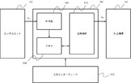
- FIG. 2 is a block diagram showing a typical example of the machining control unit shown in FIG.
- the machining control unit 140 as an example, a main control unit 142 for emitting an operation command signal S P to the processing mechanism 134 for processing unit 130, the period start time in the control cycle of the main control unit 142
- a clock unit 144 that measures the detection time T D (see FIG. 3) that received the detection signal S D from the sensor unit 120, and a memory 146 that stores various parameters including the timed detection time T D. It is configured to include.
- the main control unit 142 based on the detection time T D of the sensor unit 120 to the response delay time T-T D until the control period T, the control period T operation command signal is output to the processing unit 130 for each S It has a function to change P.
- the timekeeping unit 144 is configured as, for example, a sensor detection circuit (latch circuit) for monitoring the input of the detection signal SD from the sensor unit 120 in real time.
- the timekeeping unit 144 has a built-in counter (not shown) that counts up every 1 ⁇ sec, and this counter is preset for each control cycle of the main control unit 142 described above, and the detection signal SD is input. is a calculates the detection time T D and the response delay time T-T D is stored in the memory 146 is.
- the timer 144 and the memory 146 when a plurality of workpieces W are transported to the transport mechanism 110 calculates the time detection for the individual workpiece W T D and the response delay time T-T D storage It is configured so that it can be done. As a result, it is possible to process a plurality of workpieces W while simultaneously transporting them, so that the productivity of the entire workpiece processing apparatus 100 can be improved.
- the input interface 150 is configured as an input means capable of inputting conditions and additional information necessary for machining by a user who uses the work machining apparatus 100, and the input information and the like are transmitted to the machining control unit 140.
- Examples of such an input interface 150 include an input terminal provided with a display screen, a keyboard, and the like, a touch panel type input unit, and the like. Further, in FIG. 1, a state in which the input interface 150 is connected to the processing control unit 140 by wire is illustrated, but these may be connected by wireless communication to exchange information. ..
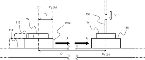
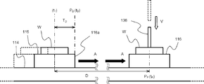
- 3A and 3B are schematic views showing an example of a reference machining state executed by the workpiece machining apparatus shown in FIG.
- the transport mechanism 110 and the machining unit 130 are independently controlled by individual control units, and the machining control of the machining unit 130 is performed from the sensor unit 120.
- a type of configuration is used that executes based on the detection signal SD. Therefore, a reference "reference machining state" is assumed between the timing when the sensor unit 120 detects the work W transported by the transport mechanism 110 and the timing when the machining unit 130 performs a predetermined machining on the work W. ..
- the tip 116a in the conveying direction A of the pallet 116 holding the workpiece W moving on a transfer path 114 along the conveying direction A, the measurement reference plane P D at time t 1 Suppose you crossed. Then, in the "reference processing state", it is defined that this time t 1 coincides with the cycle start time of the control cycle T of the main control unit 142 (for example, t 1 in FIG. 3A).
- the tip 116a of the pallet 116 is the detection target in FIG. 3A
- the tip in the transport direction A of the work W may be the detection target.
- the main control unit 142 elapses a predetermined control cycle from the time t 1 (for example, one cycle T).
- an operation command signal SP is output for each control cycle T as a distribution pulse instructing the machining mechanism 134 to drive the machining tool 136 at the moving speed V.
- FIG. 3B shows a series of these operations in relation to the elapsed time and the moving speed of the tool.
- the reference in the machining state when detecting the passage of the workpiece W at time t 1, is driven start processing tool 136 in time t 2, the predetermined period only working tool 136 acceleration period T A and equal after driving at a speed moving period T C, machining of the workpiece W is carried out in the processing position P P at time tp.
- the "reference machining state” when the cycle start time of the control cycle T of the main control unit 142 and the work detection time of the sensor unit 120 match, machining by the machining tool 136 is performed at the correct machining position of the work W. Can be executed.
- the movement of the processing tool 136 can consist of a constant speed period T C to remain at acceleration period T A and a constant speed with a constant acceleration
- acceleration period T a is capable of accelerating at any speed pattern.
- the constant speed period T C is not essential to be a constant speed, it is possible to employ any speed pattern. May be further moved a machining tool 136 only by the control acceleration period T A.
- One of the features of the machining control method according to a typical example of the present invention is the detection time when the above-mentioned sensor unit 120 detects the work W and the cycle start time when the main control unit 142 issues a command signal to the machining unit 130.
- the point is that the user can arbitrarily select a correction pattern for correcting the “deviation” with and from the input interface 150. Therefore, in the following examples, a specific embodiment of the correction pattern that can be selected by the user will be illustrated.
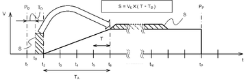
- ⁇ Example 1> 4A and 4B are schematic views showing a machining control method according to the first embodiment.
- the “delay” does not originally exist (that reference machining state) determined by calculating the delay corresponding movement amount S processing tool 136 was to be driven between the response delay time T-T D, of the delay corresponding movement amount actual machining the S tool 136 Control to add (add) to the movement speed is executed.
- the processing tool 136 is moved until the next cycle start time based on the response delay time T-T D and it calculates a delay corresponding movement amount S that generates an operation command signal S P which is changed according to the moving speed V delay corresponding movement amount S of the processing tool 136.
- the main control unit 142 the modified control command signal S P, as described above in a predetermined cycle start time of the detection time t D after it receives the detection signal S D from the sensor unit 120 for each control period T Output. That is, in Example 1, with respect to the machining control in the "reference machining state" shown in FIG.
- the main control unit 142 corresponding to the delay corresponding movement amount S that is calculated based on the response delay time T-T D speed min to only by outputting the machining unit 130 to acceleration period T in the section a hasten the moving speed V of the working tool 136 (for plus) control command signal S P as a distribution pulse signal for each control period T, workpiece
- the machining timing of the machining tool 136 contact timing between the machining tool 136 and the work W) corresponding to the W detection delay is adjusted.
- FIG. 4B shows a series of these operations in relation to the elapsed time and the moving speed of the tool.
- the main control unit 142 which has received the detection signal S D outputs a control command signal S P to start driving the working tool 136 at detection time t D after the predetermined period start time (e.g., time t 2).
- the main control unit 142 during operation of the working tool 136, in the form of additional (plus) a speed corresponding to the delay corresponding movement amount S that is calculated as described above during the acceleration period T A, the working tool 136 as the moving speed V is taken into account the delay corresponding movement amount S equivalent rate response delay time T-T D, and outputs a control command signal S P which is changed every control period T as a distribution pulse.
- the response delay time T-T D corresponding to the detection time T D which has detected the work W, thereby executing the processing by the processing tool 136 in the correct machining position of the workpiece W.
- Example 2> 5A and 5B are schematic views showing a machining control method according to the second embodiment.
- the control method shown in Example 1 is the section length of the acceleration period T A as the user has to arbitrarily select.
- the processing that receives the detection signal S D at the detection time t D the control unit 140, in the same manner as in example 1, the main control unit 142, thereby calculating a delay corresponding movement amount S based on the response delay time T-T D, the delay equivalent amount of movement the movement speed V of the machining tool 136 S the control command signal S P which has been changed in response to, the detection signal S D detection time t D after the predetermined period start time receives from the sensor unit 120, and outputs as a distribution pulse every control cycle T.
- the user selects and inputs the section length of the acceleration period TA (the length that is an integral multiple of the control cycle) from the input interface 150 in advance.
- FIG. 5B shows a series of these operations in relation to the elapsed time and the moving speed of the tool.
- the sensor unit 120 passes through the work W at the detection time t D, which is delayed by the detection time T D from the time t 1, for example, as in the case of the first embodiment.
- the output of the control command signal S P to start driving the working tool 136 at detection time t D after the predetermined period start time (e.g., time t 2) do.
- the processing tool 136 to start driving the detection time t D is calculated using the number 1 described above the delay corresponding movement amount S which is assumed to have moved until time t 2.
- the main control unit 142 during operation of the working tool 136, (section from time t 2 ⁇ t 6) the speed corresponding to the calculated delay corresponds movement amount S, pre-acceleration period user selected T A by changing the form to be added (plus) in, so that the moving speed V is the response delay time T-T delay corresponding movement amount considering D S equivalent speed of the processing tool 136, for each control period T
- the control command signal SP is output to.
- Example 2 in consideration of the response delay time T-T D corresponding to the detection time T D which has detected the work W, is to perform machining by the machining tool 136 in the correct machining position of the workpiece W can.
- a constant velocity improving the accuracy of the speed control in the moving period T C is also possible.
- FIGS. 6A and 6B are schematic views showing a machining control method according to the third embodiment. Machining control method according to the third embodiment, based on the selection of the user is obtained by that performed during the correction constant velocity moving period T C of the moving speed V of the machining tool 136.
- FIG. 6B shows these series of operations in relation to the elapsed time and the moving speed of the tool.
- the sensor unit 120 passes through the work W at the detection time t D, which is delayed by the detection time T D from the time t 1, for example, as in the case of the first embodiment.
- the output of the control command signal S P to start driving the working tool 136 at detection time t D after the predetermined period start time (e.g., time t 2) do.
- the main control unit 142 uses the above-mentioned number 1 to set the delay-equivalent movement amount S, which is assumed to have started driving at the detection time t D and the machining tool 136 has moved by the time t 2. And calculate. Then, during the operation of the machining tool 136, the speed corresponding to the calculated delay corresponds movement amount S, pre-control command signal the user changes a form to be added (plus) in the constant speed during the moving period T C selected S P is output for each control cycle T.
- Example 4> 7A and 7B are schematic views showing a machining control method according to the fourth embodiment.
- the correction of the moving speed V of the machining tool 136 is added (added) evenly from the start of the movement of the machining tool 136 based on the user's selection.
- FIG. 7B shows these series of operations in relation to the elapsed time and the moving speed of the tool.
- the machining control method according to an embodiment 4, as in Example 1 passed through the sensor unit 120 of the workpiece W at the detection time t D delayed by the detection time T D, for example, from time t 1 Upon detection of the main control unit 142 which has received the detection signal S D, the output of the control command signal S P to start driving the working tool 136 at detection time t D after the predetermined period start time (e.g., time t 2) do.
- start time e.g., time t 2
- the main control unit 142 if the number 1 described above the delay corresponding movement amount S which is assumed to have moved until the detection time t D machining tool 136 starts driving the the time t 2 Calculate using. Then, while the machining tool 136 is being driven, the speed corresponding to the calculated delay equivalent movement amount S is changed by adding the speed corresponding to the calculated delay equivalent movement amount S evenly (at a constant speed) from the start of the movement of the machining tool 136 as selected in advance by the user. and outputs the control command signal S P for each control period T.
- the working tool 136 moving speed V is detected considering the response delay time T D corresponding to the time T D of delay corresponding movement amount S equivalent rate of processing by the processing tool 136 in the correct machining position of the workpiece W Can be executed.
- the parameter for correcting the moving speed V of the machining tool 136 based on the delay equivalent moving amount S can be further arbitrarily set.
- the correction completion time is input in advance and the speed is added in equal parts within the correction completion time, or the correction completion distance (movement amount) of the machining tool 136 is input in advance.
- the speed may be added evenly within the correction completion distance.
- Example 5> 8A and 8B are schematic views showing a machining control method according to the fifth embodiment. Machining control method according to Example 5, based on the selection of the user, a correction of the movement velocity V of the machining tool 136, the acceleration period T gradually increases vital constant velocity speed Additions In A moving period T C gradually in I tried to make it smaller.
- FIG. 8B shows these series of operations in relation to the elapsed time and the moving speed of the tool.
- the machining control method according to an embodiment 5, as in Example 1 passed through the sensor unit 120 of the workpiece W at the detection time t D delayed by the detection time T D, for example, from time t 1 Upon detection of the main control unit 142 which has received the detection signal S D, the output of the control command signal S P to start driving the working tool 136 at detection time t D after the predetermined period start time (e.g., time t 2) do.
- start time e.g., time t 2
- the main control unit 142 uses the above-mentioned number 1 to set the delay-equivalent movement amount S, which is assumed to have started driving at the detection time t D and the machining tool 136 has moved by the time t 2. And calculate. Then, the processing during the operation of the tool 136, the calculated delay corresponds movement amount the rate corresponding to the S, pre-user gradually increased life and death rate Additions in the acceleration period T A as the selected constant speed movement period T and it outputs the control command signal S P to change in a way that gradually the C decreased every control period T.
- the working tool 136 moving speed V is detected considering the response delay time T D corresponding to the time T D of delay corresponding movement amount S equivalent rate of processing by the processing tool 136 in the correct machining position of the workpiece W Can be executed. Further, according to the control of this embodiment, the speed transition of the machining tool 136 can be smoothed.
- FIG. 9 is a block diagram showing a modified example of the machining control unit shown in FIG.
- the processing control unit 140 according to the modified example, as an example, the main control unit 142, a timer unit 144, a memory 146, the response delay time corresponding to the detection time T D T-T D a change command creation portion 148 to create a separate distribution pulses components for changing the operation command signal S P which is output to the processing unit 130 on the basis configured to include.
- the change command creation unit 148 independently of the main control unit 142 in this way, the operating load thereof can be reduced as compared with the case where the main control unit 142 creates the change command.
- the processing of the processing unit is performed based on the detection signal from the sensor unit that detects the passage of the moving work.
- the detection time at which the detection signal is received is measured with respect to the cycle start time in the predetermined control cycle for controlling the machining mechanism, and the detection time is set to the detection time. Since the operation command signal to the machining mechanism is changed for each control cycle based on the corresponding response delay time to control the machining tool, when controlling the machining device for machining the workpiece moving at a predetermined speed. , It is possible to suppress a decrease in machining accuracy due to a deviation between the control cycle and the work detection timing.
- the control cycle has been the limit of the accuracy of the displacement correction of the workpiece, as described above.
- the clock period of the counter of the time measuring unit is the correction accuracy limit, the correction accuracy for the displacement of the work is remarkably improved. For example, if the work transfer speed is 18 m / min, the control cycle of the main control unit is 10 msec, and the clock period of the timekeeping unit is 1 ⁇ sec, the positioning accuracy of the main control unit alone will be a maximum of about 3 mm. On the other hand, according to the above embodiment, the positioning accuracy can be improved up to about 0.3 mm.
- the present invention is not limited to the above embodiment, and can be appropriately modified without departing from the spirit.
- a case has been exemplified for performing the operations timer unit 144 calculates the response delay time T-T D from the detection time T D, the operation of calculating the response delay time T-T D It may be configured to be executed by the main control unit 142.
Landscapes
- Engineering & Computer Science (AREA)
- Physics & Mathematics (AREA)
- General Physics & Mathematics (AREA)
- Automation & Control Theory (AREA)
- Manufacturing & Machinery (AREA)
- General Engineering & Computer Science (AREA)
- Quality & Reliability (AREA)
- Mechanical Engineering (AREA)
- Human Computer Interaction (AREA)
- Numerical Control (AREA)
- Control Of Position Or Direction (AREA)
Priority Applications (4)
| Application Number | Priority Date | Filing Date | Title |
|---|---|---|---|
| CN202180012308.6A CN115039050B (zh) | 2020-02-03 | 2021-02-01 | 工件加工装置及加工控制方法 |
| DE112021000838.2T DE112021000838B4 (de) | 2020-02-03 | 2021-02-01 | Werkstückbearbeitungsvorrichtung und bearbeitungssteuerverfahren |
| US17/759,923 US12377506B2 (en) | 2020-02-03 | 2021-02-01 | Workpiece machining device and machining control method |
| JP2021575790A JP7316389B2 (ja) | 2020-02-03 | 2021-02-01 | ワーク加工装置及び加工制御方法 |
Applications Claiming Priority (2)
| Application Number | Priority Date | Filing Date | Title |
|---|---|---|---|
| JP2020016600 | 2020-02-03 | ||
| JP2020-016600 | 2020-02-03 |
Publications (1)
| Publication Number | Publication Date |
|---|---|
| WO2021157538A1 true WO2021157538A1 (ja) | 2021-08-12 |
Family
ID=77199305
Family Applications (1)
| Application Number | Title | Priority Date | Filing Date |
|---|---|---|---|
| PCT/JP2021/003605 Ceased WO2021157538A1 (ja) | 2020-02-03 | 2021-02-01 | ワーク加工装置及び加工制御方法 |
Country Status (5)
| Country | Link |
|---|---|
| US (1) | US12377506B2 (https=) |
| JP (1) | JP7316389B2 (https=) |
| CN (1) | CN115039050B (https=) |
| DE (1) | DE112021000838B4 (https=) |
| WO (1) | WO2021157538A1 (https=) |
Cited By (1)
| Publication number | Priority date | Publication date | Assignee | Title |
|---|---|---|---|---|
| JPWO2022244564A1 (https=) * | 2021-05-21 | 2022-11-24 |
Citations (2)
| Publication number | Priority date | Publication date | Assignee | Title |
|---|---|---|---|---|
| JPH1032001A (ja) * | 1996-07-15 | 1998-02-03 | Furukawa Battery Co Ltd:The | 鉛蓄電池用極板前駆体の切断制御方法 |
| JP2010044449A (ja) * | 2008-08-08 | 2010-02-25 | Fuji Electric Holdings Co Ltd | 位置制御装置 |
Family Cites Families (14)
| Publication number | Priority date | Publication date | Assignee | Title |
|---|---|---|---|---|
| JP2899075B2 (ja) * | 1990-06-29 | 1999-06-02 | 三菱電機株式会社 | 同期駆動装置および同期駆動方法 |
| JP3203816B2 (ja) | 1992-09-26 | 2001-08-27 | 豊田工機株式会社 | サーボ制御装置 |
| JP3282871B2 (ja) * | 1993-02-25 | 2002-05-20 | エヌティエヌ株式会社 | 研削加工におけるワークの寸法制御方法 |
| JPH0760609A (ja) * | 1993-08-31 | 1995-03-07 | Ntn Corp | 研削加工制御系の応答遅れ時間測定方法及び装置 |
| US6418356B1 (en) * | 1998-12-31 | 2002-07-09 | Silicon Valley Group, Inc. | Method and apparatus for resolving conflicts in a substrate processing system |
| WO2010010078A1 (en) * | 2008-07-23 | 2010-01-28 | Abb Technology Ab | Method and apparatus for hybrid conveyance for manufacturing |
| US9606532B2 (en) * | 2014-01-29 | 2017-03-28 | Taiwan Semiconductor Manufacturing Company Limited | Method and manufacturing system |
| US9632499B2 (en) * | 2014-11-03 | 2017-04-25 | GlobalFoundries, Inc. | Work-in-progress substrate processing methods and systems for use in the fabrication of integrated circuits |
| JP6333915B2 (ja) | 2016-10-20 | 2018-05-30 | ファナック株式会社 | 数値制御装置 |
| JP6469065B2 (ja) | 2016-10-28 | 2019-02-13 | ファナック株式会社 | 機械学習装置及び加工時間予測装置 |
| JP2018097661A (ja) * | 2016-12-14 | 2018-06-21 | オムロン株式会社 | 生産システム、制御装置、および制御方法 |
| JP7047249B2 (ja) * | 2017-01-10 | 2022-04-05 | オムロン株式会社 | 画像処理システム、画像処理装置、ワークのピックアップ方法、および、ワークのピックアッププログラム |
| EP3418834B1 (en) * | 2017-06-21 | 2021-08-18 | EWAB Engineering AB | Conveyor system method of operating a conveyor system and flow devices for use in such conveyor system |
| JP2019050096A (ja) * | 2017-09-08 | 2019-03-28 | 株式会社豊田自動織機 | バイポーラ電極の製造方法及びバイポーラ電極の製造装置 |
-
2021
- 2021-02-01 WO PCT/JP2021/003605 patent/WO2021157538A1/ja not_active Ceased
- 2021-02-01 US US17/759,923 patent/US12377506B2/en active Active
- 2021-02-01 JP JP2021575790A patent/JP7316389B2/ja active Active
- 2021-02-01 DE DE112021000838.2T patent/DE112021000838B4/de active Active
- 2021-02-01 CN CN202180012308.6A patent/CN115039050B/zh active Active
Patent Citations (2)
| Publication number | Priority date | Publication date | Assignee | Title |
|---|---|---|---|---|
| JPH1032001A (ja) * | 1996-07-15 | 1998-02-03 | Furukawa Battery Co Ltd:The | 鉛蓄電池用極板前駆体の切断制御方法 |
| JP2010044449A (ja) * | 2008-08-08 | 2010-02-25 | Fuji Electric Holdings Co Ltd | 位置制御装置 |
Cited By (2)
| Publication number | Priority date | Publication date | Assignee | Title |
|---|---|---|---|---|
| JPWO2022244564A1 (https=) * | 2021-05-21 | 2022-11-24 | ||
| JP7833639B2 (ja) | 2021-05-21 | 2026-03-23 | パナソニックIpマネジメント株式会社 | モータ制御方法、モータ制御装置、モータ制御システム、およびプログラム |
Also Published As
| Publication number | Publication date |
|---|---|
| DE112021000838B4 (de) | 2025-10-23 |
| JP7316389B2 (ja) | 2023-07-27 |
| CN115039050A (zh) | 2022-09-09 |
| US12377506B2 (en) | 2025-08-05 |
| CN115039050B (zh) | 2025-07-04 |
| US20230069227A1 (en) | 2023-03-02 |
| DE112021000838T5 (de) | 2022-12-08 |
| JPWO2021157538A1 (https=) | 2021-08-12 |
Similar Documents
| Publication | Publication Date | Title |
|---|---|---|
| JP5778788B2 (ja) | S字形スプリングを搬送する装置および方法 | |
| JP2003103366A (ja) | ア−ク溶接装置 | |
| KR20030049325A (ko) | 아크용접장치와 그 제어방법 | |
| JP2007030087A (ja) | 物流トラッキング装置 | |
| WO2021157538A1 (ja) | ワーク加工装置及び加工制御方法 | |
| JP2015174142A (ja) | 干渉回避装置 | |
| EP1899104A1 (en) | Method for welding work pieces | |
| CN112496557A (zh) | 镭射打标系统及镭射打标方法 | |
| CN100546755C (zh) | 激光加工系统 | |
| KR20200131734A (ko) | 공작 기계 및 공작 기계의 제어 방법 | |
| JP2003205428A5 (https=) | ||
| JP4436809B2 (ja) | レーザ加工システム | |
| WO2022118704A1 (ja) | 生産システム | |
| JPH1190778A (ja) | 切断機能を有する自動h鋼加工機の制御方法 | |
| JP2005178172A (ja) | 木材プレカット加工機 | |
| JPH08174476A (ja) | 走行切断装置 | |
| JP7692866B2 (ja) | 工作機械システム | |
| JP5980042B2 (ja) | 搬送装置の制御方法及び搬送システム | |
| JPWO2021157538A5 (https=) | ||
| JPS63295085A (ja) | Cncレ−ザ加工方法 | |
| JP7414494B2 (ja) | ロボット作業システム | |
| JP4818518B2 (ja) | 材料端面自動検出方法 | |
| JP2004167770A (ja) | プレカット加工材の位置決め加工装置 | |
| JPH0985657A (ja) | ロボットの制御装置 | |
| JPH04100676A (ja) | 倣いガス切断装置及び方法 |
Legal Events
| Date | Code | Title | Description |
|---|---|---|---|
| 121 | Ep: the epo has been informed by wipo that ep was designated in this application |
Ref document number: 21750920 Country of ref document: EP Kind code of ref document: A1 |
|
| ENP | Entry into the national phase |
Ref document number: 2021575790 Country of ref document: JP Kind code of ref document: A |
|
| 122 | Ep: pct application non-entry in european phase |
Ref document number: 21750920 Country of ref document: EP Kind code of ref document: A1 |
|
| WWG | Wipo information: grant in national office |
Ref document number: 202180012308.6 Country of ref document: CN |
|
| WWG | Wipo information: grant in national office |
Ref document number: 17759923 Country of ref document: US |
|
| WWG | Wipo information: grant in national office |
Ref document number: 112021000838 Country of ref document: DE |