WO2021152918A1 - 検知システム、検知装置および検知方法 - Google Patents
検知システム、検知装置および検知方法 Download PDFInfo
- Publication number
- WO2021152918A1 WO2021152918A1 PCT/JP2020/038089 JP2020038089W WO2021152918A1 WO 2021152918 A1 WO2021152918 A1 WO 2021152918A1 JP 2020038089 W JP2020038089 W JP 2020038089W WO 2021152918 A1 WO2021152918 A1 WO 2021152918A1
- Authority
- WO
- WIPO (PCT)
- Prior art keywords
- signal
- measurement
- unit
- detection
- transmission line
- Prior art date
- Legal status (The legal status is an assumption and is not a legal conclusion. Google has not performed a legal analysis and makes no representation as to the accuracy of the status listed.)
- Ceased
Links
Images






Classifications
-
- H—ELECTRICITY
- H04—ELECTRIC COMMUNICATION TECHNIQUE
- H04L—TRANSMISSION OF DIGITAL INFORMATION, e.g. TELEGRAPHIC COMMUNICATION
- H04L7/00—Arrangements for synchronising receiver with transmitter
- H04L7/0054—Detection of the synchronisation error by features other than the received signal transition
-
- H—ELECTRICITY
- H04—ELECTRIC COMMUNICATION TECHNIQUE
- H04B—TRANSMISSION
- H04B3/00—Line transmission systems
- H04B3/02—Details
- H04B3/46—Monitoring; Testing
-
- H—ELECTRICITY
- H04—ELECTRIC COMMUNICATION TECHNIQUE
- H04B—TRANSMISSION
- H04B10/00—Transmission systems employing electromagnetic waves other than radio-waves, e.g. infrared, visible or ultraviolet light, or employing corpuscular radiation, e.g. quantum communication
- H04B10/07—Arrangements for monitoring or testing transmission systems; Arrangements for fault measurement of transmission systems
- H04B10/075—Arrangements for monitoring or testing transmission systems; Arrangements for fault measurement of transmission systems using an in-service signal
- H04B10/079—Arrangements for monitoring or testing transmission systems; Arrangements for fault measurement of transmission systems using an in-service signal using measurements of the data signal
- H04B10/0795—Performance monitoring; Measurement of transmission parameters
-
- H—ELECTRICITY
- H04—ELECTRIC COMMUNICATION TECHNIQUE
- H04L—TRANSMISSION OF DIGITAL INFORMATION, e.g. TELEGRAPHIC COMMUNICATION
- H04L7/00—Arrangements for synchronising receiver with transmitter
- H04L7/02—Speed or phase control by the received code signals, the signals containing no special synchronisation information
-
- H—ELECTRICITY
- H04—ELECTRIC COMMUNICATION TECHNIQUE
- H04L—TRANSMISSION OF DIGITAL INFORMATION, e.g. TELEGRAPHIC COMMUNICATION
- H04L12/00—Data switching networks
- H04L12/28—Data switching networks characterised by path configuration, e.g. LAN [Local Area Networks] or WAN [Wide Area Networks]
- H04L12/40—Bus networks
-
- H—ELECTRICITY
- H04—ELECTRIC COMMUNICATION TECHNIQUE
- H04L—TRANSMISSION OF DIGITAL INFORMATION, e.g. TELEGRAPHIC COMMUNICATION
- H04L12/00—Data switching networks
- H04L12/28—Data switching networks characterised by path configuration, e.g. LAN [Local Area Networks] or WAN [Wide Area Networks]
- H04L12/40—Bus networks
- H04L2012/40208—Bus networks characterized by the use of a particular bus standard
- H04L2012/40215—Controller Area Network CAN
-
- H—ELECTRICITY
- H04—ELECTRIC COMMUNICATION TECHNIQUE
- H04L—TRANSMISSION OF DIGITAL INFORMATION, e.g. TELEGRAPHIC COMMUNICATION
- H04L12/00—Data switching networks
- H04L12/28—Data switching networks characterised by path configuration, e.g. LAN [Local Area Networks] or WAN [Wide Area Networks]
- H04L12/40—Bus networks
- H04L2012/40267—Bus for use in transportation systems
- H04L2012/40273—Bus for use in transportation systems the transportation system being a vehicle
-
- H—ELECTRICITY
- H04—ELECTRIC COMMUNICATION TECHNIQUE
- H04L—TRANSMISSION OF DIGITAL INFORMATION, e.g. TELEGRAPHIC COMMUNICATION
- H04L25/00—Baseband systems
- H04L25/02—Details ; arrangements for supplying electrical power along data transmission lines
- H04L25/0202—Channel estimation
- H04L25/0212—Channel estimation of impulse response
Definitions
- the present disclosure relates to detection systems, detection devices and detection methods. This application claims priority on the basis of Japanese Application Japanese Patent Application No. 2020-14866 filed on January 31, 2020 and incorporates all of its disclosures herein.
- Patent Document 1 Japanese Unexamined Patent Publication No. 2011-22555 discloses the following impulse response measurement method. That is, the impulse response measurement method has an input signal generation step of generating an input signal of an arbitrary waveform to be input to the system under test using a synchronization signal having a first sampling clock frequency, and a second sampling clock frequency. A signal conversion step of converting a signal under test output from the system under test into a discrete value system using a synchronization signal, and a frequency ratio between the first sampling clock frequency and the second sampling clock frequency. It has an inverse filter correction step that at least corrects the phase of the inverse filter, which is an inverse function of the function indicating the frequency characteristic of the input signal according to the above, and uses the corrected inverse filter to impulse the system to be measured. Measure the response.
- Patent Document 2 Japanese Unexamined Patent Publication No. 3-64657 discloses the following method for measuring an impulse response. That is, in the method of measuring the impulse response, the discrete impulse response of the system under test is measured by using a non-impulse arbitrary waveform input signal with respect to the system under test for continuous time invariant with linear time and an inverse filter of the input signal.
- the input signal has a flat spectrum at all discrete frequencies, the phase characteristics are continuous and proportional to the square of the discrete frequency, and the input signal is discrete at a discrete frequency of 1/2 the sample size. It is a waveform such that the target Fourier transform is 1 + j0.
- Patent Document 3 Japanese Unexamined Patent Publication No. 8-145846 discloses the following optical frequency domain reflection measurement method. That is, in the optical frequency region reflection measurement method, in the optical frequency region reflection measurement, the reference light from the optical frequency sweep light source to the direct optical receiver and the light receiver after being reflected from the optical frequency sweep light source inside the light component to be measured are used. By inserting a delayed optical fiber in the reference optical path or signal optical path so that the optical path length difference from the signal light to reach is N times or more the length of the optical component to be measured, the output light of the optical frequency sweep light source becomes higher order. When the modulated side band component of (N-1) is included, the frequency band occupied by the beat signal generated due to the (N-1) or lower modulation side band component is separated.
- Patent Document 4 Japanese Unexamined Patent Publication No. 7-96584 discloses the following acoustic characteristic correction device. That is, the acoustic characteristic correction device inputs a measurement signal generating means that outputs a TSP signal as a measurement signal, and a signal that reproduces the generated measurement signal with a speaker and picks up the sound with a microphone to input the TSP signal.
- the inverse filter means for obtaining the impulse response by time compression by the convolution operation with the inverse filter characteristic of, and the measurement characteristic information of the response characteristic of the reproduction system including the sound field are obtained by frequency-converting the obtained impulse response.
- Acoustic characteristic correction including a correction characteristic calculation means for calculating the correction characteristic of the response characteristic for the purpose and a correction characteristic imparting means for imparting the calculated correction characteristic to the acoustic signal to be reproduced by a convolution calculation.
- the inverse filter means and the correction characteristic imparting means use a common convolution calculator to perform a convolution calculation.
- the detection system of the present disclosure includes a signal output unit that outputs a measurement signal that changes with a predetermined time to a measurement target, a signal measurement unit that measures a response signal from the measurement target to the measurement signal, and the signal measurement.
- a calculation unit that calculates the impulse response of the measurement target based on the measurement result of the response signal by the unit, and a detection unit that detects an abnormality related to the measurement target based on the impulse response calculated by the calculation unit. To be equipped.
- the detection device of the present disclosure includes a signal output unit that outputs a measurement signal that changes with a predetermined time to a measurement target, and a signal measurement unit that measures a response signal from the measurement target to the measurement signal.
- the detection method of the present disclosure is a detection method in a detection system, and is a step of outputting a measurement signal that changes with a predetermined time to a measurement target and a step of measuring a response signal from the measurement target to the measurement signal.
- a step of calculating an impulse response of the measurement target based on the measurement result of the response signal, and a step of detecting an abnormality related to the measurement target based on the calculated impulse response are included.
- One aspect of the present disclosure can be realized not only as a detection system provided with such a characteristic processing unit, but also as a semiconductor integrated circuit that realizes a part or all of the detection system, or processing in the detection system. It can be realized as a program for causing a computer to execute a step. Further, one aspect of the present disclosure can be realized not only as a detection device provided with such a characteristic processing unit, but also as a semiconductor integrated circuit that realizes a part or all of the detection device, or in a detection device. It can be realized as a program for causing a computer to execute a processing step.
- FIG. 1 is a diagram showing a configuration of a communication system according to the first embodiment of the present disclosure.
- FIG. 2 is a diagram showing a configuration of an in-vehicle device group according to the first embodiment of the present disclosure.
- FIG. 3 is a diagram showing a configuration of a transmission line according to the first embodiment of the present disclosure.
- FIG. 4 is a diagram showing a configuration of a signal output device according to the first embodiment of the present disclosure.
- FIG. 5 is a diagram showing an example of a measurement signal output by the signal output unit according to the first embodiment of the present disclosure.
- FIG. 6 is a diagram showing an example of a time change in the frequency of the measurement signal output by the signal output unit according to the first embodiment of the present disclosure.
- FIG. 1 is a diagram showing a configuration of a communication system according to the first embodiment of the present disclosure.
- FIG. 2 is a diagram showing a configuration of an in-vehicle device group according to the first embodiment of the present disclosure.
- FIG. 7 is a diagram showing another example of the measurement signal output by the signal output unit according to the first embodiment of the present disclosure.
- FIG. 8 is a diagram showing another example of the measurement signal output by the signal output unit according to the first embodiment of the present disclosure.
- FIG. 9 is a diagram showing another example of the measurement signal output by the signal output unit according to the first embodiment of the present disclosure.
- FIG. 10 is a diagram showing another example of the measurement signal output by the signal output unit according to the first embodiment of the present disclosure.
- FIG. 11 is a diagram showing another example of the measurement signal output by the signal output unit according to the first embodiment of the present disclosure.
- FIG. 12 is a diagram showing a configuration of a detection device according to the first embodiment of the present disclosure.
- FIG. 13 is a diagram showing an example of a response signal measured by the signal measuring unit according to the first embodiment of the present disclosure.
- FIG. 14 is a diagram showing an example of a signal having an inverse characteristic of the measurement signal output by the signal measurement unit according to the first embodiment of the present disclosure.
- FIG. 15 is a diagram showing an example of an impulse response calculated by the calculation unit according to the first embodiment of the present disclosure.
- FIG. 16 is a diagram showing an example of frequency characteristics calculated by the detection unit according to the first embodiment of the present disclosure.
- FIG. 17 is a diagram showing another example of frequency characteristics calculated by the detection unit according to the first embodiment of the present disclosure.
- FIG. 18 is a diagram showing an example of a waveform of a pulse signal used for calculating a response waveform by the detection unit according to the first embodiment of the present disclosure.
- FIG. 19 is a diagram showing an example of a response waveform calculated by the detection unit according to the first embodiment of the present disclosure.
- FIG. 20 is a diagram showing an example of a reference waveform stored in the storage unit according to the first embodiment of the present disclosure.
- FIG. 21 is a diagram showing an example of a response waveform calculated by the detection unit according to the first embodiment of the present disclosure.
- FIG. 22 is a diagram showing an example of a difference waveform calculated by the detection unit according to the first embodiment of the present disclosure.
- FIG. 23 is a flowchart defining an example of an operation procedure when the detection device according to the first embodiment of the present disclosure detects an abnormality related to a transmission line.
- FIG. 24 is a diagram showing an example of a sequence of abnormality detection processing in the detection system according to the first embodiment of the present disclosure.
- FIG. 25 is a diagram showing a configuration of an in-vehicle device group according to a second embodiment of the present disclosure.
- FIG. 26 is a diagram showing a configuration of a detection device according to a second embodiment of the present disclosure.
- FIG. 27 is a flowchart defining an example of an operation procedure when the detection device according to the second embodiment of the present disclosure detects an abnormality related to a transmission line.
- FIG. 28 is a diagram showing a configuration of an in-vehicle device group according to a third embodiment of the present disclosure.
- FIG. 29 is a diagram showing a configuration of a detection device according to a third embodiment of the present disclosure.
- the present disclosure has been made to solve the above-mentioned problems, and an object thereof is to provide a detection device, a management device, a detection method, and a detection program capable of realizing excellent functions related to security in a network. Is.
- the detection system measures a signal output unit that outputs a measurement signal that changes with a predetermined time to a measurement target, and a response signal from the measurement target to the measurement signal.
- the measurement target is based on the signal measurement unit, the calculation unit that calculates the impulse response of the measurement target based on the measurement result of the response signal by the signal measurement unit, and the impulse response calculated by the calculation unit. It is equipped with a detection unit that detects abnormalities related to.
- a measurement signal that changes over a predetermined time is output to the measurement target, and the impulse response of the measurement target is calculated based on the response signal from the measurement target, for example, TDR (Time Domain Reflectometry) and network.
- TDR Time Domain Reflectometry
- the impulse response can be calculated and abnormality can be detected with a simple configuration.
- the response signal can be measured with a high SN (Signal-Noise) ratio as compared with a configuration using a network analyzer, for example, calibration of a measuring device or the like can be easily performed.
- the response signal can be measured with a high SN ratio as compared with the configuration using the impulse signal as the measurement signal, and as a result, the non-linear noise is separated and the abnormality related to the measurement target can be more accurately detected with high reproducibility. Can be detected. Therefore, it is possible to realize excellent functions related to security in the network.
- the detection unit calculates the response waveform of the measurement target to the reference signal based on the impulse response and the waveform information of the reference signal which is a predetermined signal, and the calculated response waveform. Based on the above, the position where the abnormality occurs in the measurement target is specified.
- the detection unit performs the measurement based on a comparison result between the frequency characteristic of the impulse response and the frequency characteristic of the impulse response based on the past measurement result of the response signal by the signal measurement unit. Detect anomalies related to the target.
- the signal output unit notifies the signal measurement unit of the timing for the output of the measurement signal, and the signal measurement unit uses the timing notified from the signal output unit.
- the response signal is measured in synchronization with the signal output unit.
- the response signal from the measurement target can be measured at an appropriate timing, so that the processing load can be reduced and the response signal from the measurement target can be measured more accurately.
- the measurement target is a transmission line
- the detection unit detects the connection of a new device to the transmission line as an abnormality related to the measurement target.
- the detection device measures a signal output unit that outputs a measurement signal that changes with a predetermined time to a measurement target, and a response signal from the measurement target to the measurement signal. It is equipped with a signal measurement unit.
- the impulse response of the measurement target is calculated based on the measurement result of the response signal, for example, by the configuration in which the measurement signal that changes with a predetermined time is output to the measurement target and the response signal from the measurement target is measured.
- the response signal can be measured with a high SN ratio, so that the measuring device or the like can be easily calibrated.
- the response signal can be measured with a high SN ratio as compared with the configuration using the impulse signal as the measurement signal, and as a result, the non-linear noise is separated and the abnormality related to the measurement target can be more accurately detected with high reproducibility. Can be detected. Therefore, it is possible to realize excellent functions related to security in the network.
- the detection method according to the embodiment of the present disclosure is a detection method in a detection system, which includes a step of outputting a measurement signal that changes with a predetermined time to a measurement target, and the measurement target for the measurement signal.
- the response signal can be measured with a high SN ratio as compared with the configuration using the impulse signal as the measurement signal, and as a result, the non-linear noise is separated and the abnormality related to the measurement target can be more accurately detected with high reproducibility. Can be detected. Therefore, it is possible to realize excellent functions related to security in the network.
- FIG. 1 is a diagram showing a configuration of a communication system according to the first embodiment of the present disclosure.
- the communication system 501 includes a gateway device 20, a plurality of vehicle-mounted communication devices 30, and a plurality of vehicle-mounted device groups 40.
- the communication system 501 is mounted on the vehicle 1, for example.
- the communication system 501 may be used for a home network or factory automation.
- the in-vehicle network 12 includes a gateway device 20 and transmission lines 13 and 14.
- the plurality of in-vehicle communication devices 30 are connected to the gateway device 20 via the corresponding transmission lines 14.
- the transmission line 14 is, for example, an Ethernet® cable.
- the in-vehicle communication device 30 communicates with a device outside the vehicle 1, for example.
- the in-vehicle communication device 30 is, for example, a TCU (Telematics Communication Unit), a short-range wireless terminal device, and an ITS (Intelligent Transport Systems) radio.
- the plurality of vehicle-mounted device groups 40 are connected to the gateway device 20 via the corresponding transmission lines 13.
- the transmission line 13 complies with, for example, CAN (Control Area Network) (registered trademark), FlexRay (registered trademark), MOST (Media Oriented Systems Transport) (registered trademark), Ethernet, and LIN (Local Internet transmission). It is a line.
- FIG. 2 is a diagram showing a configuration of an in-vehicle device group according to the first embodiment of the present disclosure.
- the in-vehicle device group 40 is connected to the gateway device 20 via a corresponding bus according to the CAN standard, which is an example of the transmission line 13.
- the in-vehicle device group 40 includes a detection system 401 and a plurality of control devices 101 connected to the transmission line 13.
- the in-vehicle device group 40 has a bus-type topology.
- the gateway device 20, the in-vehicle communication device 30, and the control device 101 are examples of the in-vehicle device.
- the control device 101 communicates with another vehicle-mounted device connected to the vehicle-mounted network 12 via the transmission line 13. For example, the control device 101 transmits a signal including various information to the gateway device 20 via the transmission line 13.
- the control device 101 is, for example, an ECU (Electronic Control Unit).
- the in-vehicle device group 40 is not limited to the configuration including a plurality of control devices 101, and may be configured to include one control device 101. Further, the in-vehicle device group 40 may include devices such as actuators and sensors connected to the transmission line 13 as in-vehicle devices.
- the transmission line 13 is provided for each system, for example.
- the transmission line 13 is, for example, a drive system bus, a chassis / safety system bus, a body / electrical system bus, and an AV / information system bus.
- An engine control device, an AT (Automatic Transmission) control device, and a HEV (Hybrid Electric Vehicle) control device, which are examples of the control device 101, are connected to the drive system bus.
- the engine control device, the AT control device, and the HEV control device control the engine, the AT, and the switching between the engine and the motor, respectively.
- a brake control device, a chassis control device, and a steering control device which are examples of the control device 101, are connected to the chassis / safety system bus.
- the brake control device, chassis control device and steering control device control the brake, chassis and steering, respectively.
- An instrument display control device, an air conditioner control device, an anti-theft control device, an airbag control device, and a smart entry control device which are examples of the control device 101, are connected to the body / electrical system bus.
- the instrument display control device, the air conditioner control device, the anti-theft control device, the air bag control device, and the smart entry control device control the instrument, the air conditioner, the anti-theft mechanism, the air bag mechanism, and the smart entry, respectively.
- the AV / information system bus is connected to a navigation control device, an audio control device, an ETC (Electronic Toll Collection System) (registered trademark) control device, and a telephone control device, which are examples of the control device 101.
- the navigation control device, the audio control device, the ETC control device, and the telephone control device control the navigation device, the audio device, the ETC device, and the mobile phone, respectively.
- the gateway device 20 is, for example, a central gateway (CGW), and can communicate with other in-vehicle devices.
- CGW central gateway
- the gateway device 20 is, for example, in the vehicle 1, information exchanged between the in-vehicle device groups 40 connected to different transmission lines 13, information exchanged between each in-vehicle communication device 30, the in-vehicle device group 40 and the in-vehicle communication device. A relay process for relaying information exchanged between 30 is performed.
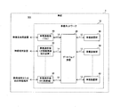
- the detection system 401 includes a signal output device 200 and a detection device 300.
- the signal output device 200 and the detection device 300 are connected to each other via a transmission line 15.
- the signal output device 200 and the detection device 300 are connected to the transmission line 13. More specifically, for example, the signal output device 200 is connected to the vicinity of the first end of the transmission line 13 on the gateway device 20 side, and the detection device 300 is the second device on the transmission line 13 opposite to the gateway device 20. Connected to the end.
- FIG. 3 is a diagram showing a configuration of a transmission line according to the first embodiment of the present disclosure.
- FIG. 3 shows the configuration of the transmission line 13.
- the transmission line 13 includes connectors 23A, 23B, connectors 33, a plurality of connectors 43, a main line 13A, and a plurality of sub lines 13B drawn from the main line 13A.
- the transmission line 13 is a bus-type transmission line.
- the connector 23A is connected to the first end of the main line 13A.
- the connector 23B is connected to the second end of the main line 13A. That is, the main line 13A connects the connector 23A and the connector 23B.
- Each of the connectors 33 and 43 is connected to the sub line 13B.
- the gateway device 20 and the signal output device 200 are connected to the connector 23A.
- the detection device 300 is connected to the connector 23B.
- Each of the plurality of control devices 101 is connected to the connector 43.
- Connector 33 is an unused spare connector.
- the connector 33 is an open end.
- the detection system 401 detects an abnormality related to the transmission line 13 which is an example of the measurement target.
- the transmission line 13 is an example of a transmission line.
- the transmission line 13 is, for example, a linear time-invariant system.
- FIG. 4 is a diagram showing a configuration of a signal output device according to the first embodiment of the present disclosure.
- the signal output device 200 includes a signal output unit 210 and a storage unit 230.
- the signal output unit 210 is realized by a processor such as a CPU (Central Processing Unit) and a DSP (Digital Signal Processor), for example.
- the storage unit 230 is, for example, a non-volatile memory.
- the signal output unit 210 outputs a measurement signal that changes with a predetermined time to the transmission line 13.
- the signal output unit 210 outputs a measurement signal whose frequency changes with a predetermined time to the transmission line 13.
- the signal measurement unit 320 outputs the measurement signal S (t) represented as a function of the time t to the transmission line 13.
- the measurement signal is a signal used for measuring the response signal in the signal measurement unit 320, which will be described later.
- the signal output unit 210 outputs a measurement signal whose frequency changes for a predetermined time to the transmission line 13 in the output period Tout periodically or irregularly.
- the measurement signal is, for example, a sine wave signal.
- FIG. 5 is a diagram showing an example of a measurement signal output by the signal output unit according to the first embodiment of the present disclosure.
- the vertical axis is voltage and the horizontal axis is time.
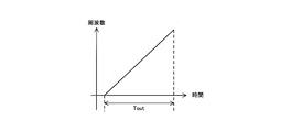
- FIG. 6 is a diagram showing an example of a time change in the frequency of the measurement signal output by the signal output unit according to the first embodiment of the present disclosure.
- the vertical axis is frequency and the horizontal axis is time.
- the signal output unit 210 sends a TSP signal (Time Stretched Pulse), which is a sine wave whose frequency increases linearly and continuously, as a measurement signal to the transmission line 13 during the output period Tout. Output.
- TSP signal Time Stretched Pulse
- the storage unit 230 stores TSP data, which is digital data of the TSP signal.
- the signal output unit 210 includes a digital-to-analog conversion circuit.
- the signal output unit 210 acquires TSP data from the storage unit 230 at an output timing according to a predetermined cycle, and converts the acquired TSP data into analog by a digital-to-analog conversion circuit, thereby transmitting a TSP signal to the transmission line 13. Output.
- the signal output unit 210 may be configured to output a signal other than the time-changing TSP signal as shown in FIG. 6 to the transmission line 13 as a measurement signal.
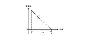
- FIGS. 7 to 11 are diagrams showing other examples of measurement signals output by the signal output unit according to the first embodiment of the present disclosure.
- the vertical axis is frequency and the horizontal axis is time.
- the signal output unit 210 may be configured to output a sine wave signal whose frequency linearly and continuously decreases to the transmission line 13 as a measurement signal during the output period Tout.
- the signal output unit 210 transmits a Log-SS (Logarithmic Swept Sine) signal, which is a sine wave whose frequency increases exponentially and continuously, as a measurement signal during the output period Tout. It may be configured to output to the line 13.
- Log-SS Logarithmic Swept Sine
- the signal output unit 210 is configured to output a sine wave signal whose frequency decreases exponentially and continuously to the transmission line 13 as a measurement signal during the output period Tout. good.
- the signal output unit 210 may be configured to output a sine wave signal whose frequency increases linearly and intermittently to the transmission line 13 as a measurement signal during the output period Tout. ..
- the signal output unit 210 may be configured to output a sine wave signal whose frequency increases intermittently to the transmission line 13 as a measurement signal during the output period Tout.
- the signal output unit 210 outputs a sinusoidal signal whose frequency linearly and intermittently decreases or a sinusoidal signal whose frequency decreases intermittently to the transmission line 13 as a measurement signal during the output period Tout. May be.
- the signal output unit 210 is one of a plurality of types of measurement signals, for example, depending on the frequency range to be noted in the detection process using the frequency characteristic H (f) generated by the detection unit 340 described later. A configuration may be used in which various types of measurement signals are selectively output to the transmission line 13.
- the signal output unit 210 notifies the detection device 300 of the timing regarding the output of the measurement signal.
- the signal output unit 210 transmits a synchronization signal indicating the timing for starting the output of the measurement signal to the detection device 300 via the transmission line 15.
- the signal output unit 210 transmits the synchronization signal to the detection device 300, the output period Tout is started, and the measurement signal is output to the transmission line 13.
- FIG. 12 is a diagram showing a configuration of a detection device according to the first embodiment of the present disclosure.
- the detection device 300 includes a communication unit 310, a signal measurement unit 320, a calculation unit 330, a detection unit 340, and a storage unit 350.
- the communication unit 310, the signal measurement unit 320, the calculation unit 330, and the detection unit 340 are realized by, for example, a processor such as a CPU and a DSP.
- the storage unit 350 is, for example, a non-volatile memory.
- the signal measurement unit 320 measures the response signal from the transmission line 13 to the measurement signal. For example, the signal measurement unit 320 measures a response signal indicating the transmission characteristic of the transmission line 13. Specifically, the signal measurement unit 320 measures the TSP signal that is output to the transmission line 13 by the signal output unit 210 of the signal output device 200 and has passed through the transmission line 13 as a response signal during the measurement period Tm.
- FIG. 13 is a diagram showing an example of a response signal measured by the signal measuring unit according to the first embodiment of the present disclosure.
- the vertical axis is voltage and the horizontal axis is time.
- the signal measurement unit 320 measures the response signal in synchronization with the signal output unit 210 by using the timing notified from the signal output unit 210.
- the measurement period Tm is started. Specifically, the signal measurement unit 320 measures the response signal on the transmission line 13 by sampling the voltage of the transmission line 13 according to a predetermined sampling cycle during the measurement period Tm.
- the length of the measurement period Tm is, for example, the same as the length of the output period Tout.
- the signal measurement unit 320 When the signal measurement unit 320 generates sampling data S by sampling the voltage of the transmission line 13 during the measurement period Tm, the signal measurement unit 320 outputs the generated sampling data S to the calculation unit 330.
- the calculation unit 330 calculates the impulse response h (t) of the transmission line 13 based on the measurement result of the response signal by the signal measurement unit 320. For example, the calculation unit 330 calculates the impulse response h (t) of the transmission line 13 based on the measurement result of the response signal by the signal measurement unit 320 and the inverse characteristic of the time change of the measurement signal.
- FIG. 14 is a diagram showing an example of a signal having an inverse characteristic of the measurement signal output by the signal measurement unit according to the first embodiment of the present disclosure.
- the vertical axis is voltage and the horizontal axis is time.
- FIG. 14 shows a signal having the opposite characteristic of the time change of the TSP signal.
- the storage unit 350 is digital data of signals S ⁇ (-1) (t) having the opposite characteristic of time change of the TSP signal output from the signal output unit 210 in the signal output device 200 to the transmission line 13.
- S ⁇ (-1) means S to the power of (-1).
- the calculation unit 330 When the calculation unit 330 receives the sampling data S from the signal measurement unit 320 for each measurement period Tm, the calculation unit 330 acquires the inverse characteristic data in the storage unit 350 and performs a convolution calculation of the sampling data S and the inverse characteristic data. , The impulse response h (t) indicating the output when the impulse signal is input to the transmission line 13 is calculated.
- FIG. 15 is a diagram showing an example of an impulse response calculated by the calculation unit according to the first embodiment of the present disclosure.
- the vertical axis is voltage and the horizontal axis is time.
- the calculation unit 330 calculates the impulse response h (t) of the transmission line 13 for each measurement period Tm, and outputs the calculation information including the calculated impulse response h (t) to the detection unit 340.
- the detection unit 340 detects an abnormality related to the transmission line 13 based on the impulse response h (t) calculated by the calculation unit 330.
- the detection unit 340 detects the connection of a new device to the transmission line 13 as an abnormality related to the transmission line 13. More specifically, the detection unit 340 detects, for example, the connection of a new device to the connector 33 on the transmission line 13 and the connection of a new connector and a new device to the transmission line 13 as an abnormality related to the transmission line 13. do.
- the detection unit 340 compares the frequency characteristic H (f) of the impulse response h (t) with the frequency characteristic H (f) of the impulse response h (t) based on the past measurement result of the response signal by the signal measurement unit 320. Based on the result, an abnormality related to the transmission line 13 is detected.
- the detection unit 340 receives the calculation information from the calculation unit 330 for each measurement period Tm, the impulse response h (t) included in the received calculation information is Fourier transformed to perform the impulse response h ( The frequency characteristic H (f) of t) is generated.
- the detection unit 340 generates the frequency characteristic H (f) for each measurement period Tm, and stores the generated frequency characteristic H (f) in the storage unit 350.
- the detection unit 340 detects an abnormality related to the transmission line 13 based on the time-series change of the frequency characteristic H (f) for each measurement period Tm.
- FIG. 16 is a diagram showing an example of frequency characteristics calculated by the detection unit according to the first embodiment of the present disclosure.
- FIG. 17 is a diagram showing another example of frequency characteristics calculated by the detection unit according to the first embodiment of the present disclosure.
- FIGS. 16 and 17 the vertical axis is frequency and the horizontal axis is time.
- FIG. 16 shows the frequency characteristic H (f) corresponding to the measurement period Tm starting from a certain time ta
- FIG. 17 shows the frequency characteristic H (f) corresponding to the measurement period Tm starting from the time tb after the time ta. ing.
- the detection unit 340 When the detection unit 340 generates the frequency characteristic H (f), the amount of change in the frequency characteristic H (f) per unit time is based on one or more frequency characteristics H (f) generated in the past in the storage unit 350. Is calculated, and the calculated amount of change is compared with the predetermined threshold value Th1. Then, when the amount of change in the frequency characteristic H (f) per unit time is equal to or greater than the predetermined threshold value Th1, the detection unit 340 determines that an abnormality related to the transmission line 13 has occurred.
- an unauthorized device may be connected to the connector 33, which is a spare connector.
- the response signal measured by the signal measuring unit 320 and the frequency characteristic H (f) generated by the detecting unit 340 change when an unauthorized device is connected to the connector 33. Therefore, the detection unit 340 can detect that an unauthorized device is connected to the connector 33 based on the time-series change of the frequency characteristic H (f) for each measurement period Tm.
- a new connector and an unauthorized device may be connected to the transmission line 13.
- the response signal measured by the signal measuring unit 320 and the frequency characteristic H (f) generated by the detecting unit 340 are changed by connecting a new connector and an unauthorized device to the transmission line 13. Therefore, the detection unit 340 can detect that a new connector and an unauthorized device are connected to the transmission line 13 based on the time-series change of the frequency characteristic H (f) for each measurement period Tm. ..
- the storage unit 350 stores the frequency characteristic Hx (f), which is the frequency characteristic H (f) when the device is connected to the connector 33.
- the detection unit 340 When the detection unit 340 generates the frequency characteristic H (f), the detection unit 340 compares the generated frequency characteristic H (f) with the frequency characteristic Hx (f) in the storage unit 350, and based on the comparison result, relates to the transmission line 13. It may be configured to detect an abnormality.
- the detection unit 340 determines that an abnormality related to the transmission line 13 has occurred, the detection unit 340 outputs determination information indicating that the abnormality has occurred to the communication unit 310.
- the communication unit 310 When the communication unit 310 receives the judgment information from the detection unit 340, the communication unit 310 generates a frame including the received judgment information, and transmits the generated frame to a higher-level device inside or outside the vehicle 1 via the transmission line 13.
- the detection unit 340 calculates the response waveform y (t) of the transmission line 13 with respect to the reference signal based on the impulse response h (t) and the waveform information of the reference signal which is a predetermined signal, and the calculated response waveform y. Based on (t), an abnormality related to the transmission line 13 is detected.
- the detection unit 340 calculates the response waveform y (t) of the transmission line 13 with respect to the pulse signal based on the impulse response h (t) and the waveform information of the pulse signal which is an example of the reference signal.
- FIG. 18 is a diagram showing an example of a pulse signal waveform used for calculating a response waveform by the detection unit according to the first embodiment of the present disclosure.
- the vertical axis is voltage and the horizontal axis is time.
- the storage unit 350 stores pulse data, which is digital data of a pulse signal.
- the detection unit 340 When the detection unit 340 receives the calculation information from the calculation unit 330 for each measurement period Tm, the detection unit 340 acquires the pulse data from the storage unit 350, and the impulse response h (t) included in the received calculation information and the convolution of the pulse data. By performing the calculation, the response waveform y (t) of the transmission line 13 with respect to the pulse signal is calculated. For example, the response waveform y (t) shows the output when a pulse signal is input to the transmission line 13.
- FIG. 19 is a diagram showing an example of a response waveform calculated by the detection unit according to the first embodiment of the present disclosure.
- the vertical axis is voltage and the horizontal axis is time.
- the storage unit 350 stores the reference waveform yref (t), which is the response waveform y (t) for reference.
- the reference waveform yref (t) is the response waveform y (t) calculated by the detection unit 340 in a state where an abnormality related to the transmission line 13 has not occurred.
- the reference waveform yref (t) is stored in the storage unit 350 by the producer of the vehicle 1 before the vehicle 1 is shipped.
- the detection unit 340 When the detection unit 340 generates the response waveform y (t) for each measurement period Tm, the detection unit 340 compares the generated response waveform y (t) with the reference waveform yref (t), and based on the comparison result, the transmission line. Detects an abnormality related to 13.
- FIG. 20 is a diagram showing an example of a reference waveform stored in the storage unit according to the first embodiment of the present disclosure.
- the vertical axis is voltage and the horizontal axis is time.
- FIG. 21 is a diagram showing an example of a response waveform calculated by the detection unit according to the first embodiment of the present disclosure.
- the vertical axis is voltage and the horizontal axis is time.
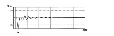
- the detection unit 340 calculates the difference waveform D (t) which is the difference between the response waveform y (t) and the reference waveform yref (t).
- the detection unit 340 compares the calculated difference waveform D (t) with the predetermined threshold values Tha and Thb, and detects an abnormality related to the transmission line 13 based on the comparison result.
- the threshold value Th is larger than the threshold value Thb.
- FIG. 22 is a diagram showing an example of a difference waveform calculated by the detection unit according to the first embodiment of the present disclosure.
- the vertical axis is voltage and the horizontal axis is time.
- the detection unit 340 detects that the voltage of the difference waveform D (t) at a certain time tx is less than the threshold value Thb, it determines that an abnormality related to the transmission line 13 has occurred.
- the response signal measured by the signal measuring unit 320 and the difference waveform D (t) calculated by the detecting unit 340 change when an unauthorized device is connected to the connector 33. Therefore, the detection unit 340 can detect that an unauthorized device is connected to the connector 33 based on the comparison result between the difference waveform D (t) and the threshold values Tha and Thb.
- the response signal measured by the signal measuring unit 320 and the difference waveform D (t) calculated by the detecting unit 340 change when a new connector and an unauthorized device are connected to the transmission line 13. Therefore, the detection unit 340 can detect that a new connector and an illegal device are connected to the transmission line 13 based on the comparison result between the difference waveform D (t) and the threshold values Tha and Thb. can.
- the storage unit 350 stores the difference waveform Dx (t) which is the difference waveform D (t) in the state where the device is connected to the connector 33.
- the detection unit 340 calculates the difference waveform D (t)
- the detected difference waveform D (t) is compared with the difference waveform Dx (t) in the storage unit 350, and the transmission line 13 is related based on the comparison result. It may be configured to detect an abnormality.
- the detection unit 340 stores the generated response waveform y (t) in the storage unit 350, and detects an abnormality related to the transmission line 13 based on the time-series change of the response waveform y (t) for each measurement period Tm. It may be configured to detect.
- the detection unit 340 identifies an abnormality occurrence position on the transmission line 13 based on the calculated response waveform y (t).
- the detection unit 340 causes an abnormality in the transmission line 13 based on the time when the difference waveform D (t) exceeds the threshold value Th and the time when the difference waveform D (t) becomes less than the threshold value Thb. Identify the location of occurrence. For example, the detection unit 340 identifies an abnormality occurrence position on the transmission line 13 based on the time tx shown in FIG. Specifically, the detection unit 340 identifies the abnormality occurrence position by calculating the distance from the signal output device 200 on the transmission line 13 to the abnormality occurrence position according to the time tx.
- the detection unit 340 determines that an abnormality related to the transmission line 13 has occurred, the detection unit 340 transmits the determination information indicating the occurrence of the abnormality and the position where the abnormality has occurred to the host device inside or outside the vehicle 1 via the communication unit 310 and the transmission line 13. Send to.
- the detection unit 340 may be configured not to perform at least one of the detection processing of the detection example 1 and the detection processing of the detection example 2 described above, or other than the detection processing of the detection examples 1 and 2. It may be configured to perform detection processing.
- Each device in the detection system includes a computer including a memory, and an arithmetic processing unit such as a CPU in the computer includes a program including a part or all of each step of the following flowchart and sequence. Read from the memory and execute. The programs of these plurality of devices can be installed from the outside. The programs of these plurality of devices are distributed in a state of being stored in a recording medium.
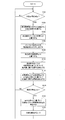
- FIG. 23 is a flowchart defining an example of an operation procedure when the detection device according to the first embodiment of the present disclosure detects an abnormality related to a transmission line.
- step S104 when the detection device 300 listens for the synchronization signal from the signal output unit 210 in the signal output device 200 (NO in step S102) and receives the synchronization signal (YES in step S102), the measurement period At Tm, the response signal from the transmission line 13 to the measurement signal is measured (step S104).
- the detection device 300 calculates the impulse response h (t) of the transmission line 13 based on the measurement result of the response signal and the inverse characteristic of the time change of the measurement signal (step S106).
- the detection device 300 generates the frequency characteristic H (f) of the impulse response h (t) by Fourier transforming the impulse response h (t), and stores the generated frequency characteristic H (f) in the storage unit 350. It is saved in (step S108).
- the detection device 300 calculates the response waveform y (t) of the transmission line 13 with respect to the pulse signal by performing the impulse response h (t) and the convolution calculation of the pulse data (step S110).
- the detection device 300 detects an abnormality related to the transmission line 13 based on the time-series change of the frequency characteristic H (f) for each measurement period Tm in the storage unit 350 (step S112).
- the detection device 300 detects an abnormality related to the transmission line 13 based on the difference waveform D (f), which is the difference between the response waveform y (t) and the reference waveform yref (t) (step S114).
- the detection device 300 determines that an abnormality related to the transmission line 13 has not occurred (NO in step S116).
- the detection device 300 waits for a new synchronization signal from the signal output unit 210 in the signal output device 200 (NO in step S102). ).
- the detection device 300 determines that an abnormality has occurred in the transmission line 13 (YES in step S116)
- the detection device 300 identifies the abnormality occurrence position in the transmission line 13 based on the difference waveform D (f) (step S118).
- the detection device 300 transmits the determination information indicating that an abnormality has occurred in the transmission line 13 and the position where the abnormality has occurred to a higher-level device inside or outside the vehicle 1 via the transmission line 13 (step S120).
- the detection device 300 waits for a new synchronization signal from the signal output unit 210 in the signal output device 200 (NO in step S102).
- the detection device 300 may be configured not to perform at least one of steps S108 and S112 and steps S110 and S114. Further, the detection device 300 may be configured not to perform at least one of step S118 and step S120.
- FIG. 24 is a diagram showing an example of a sequence of abnormality detection processing in the detection system according to the first embodiment of the present disclosure.
- the signal output unit 210 in the signal output device 200 transmits a synchronization signal indicating the timing for starting the output of the measurement signal to the signal measurement unit 320 in the detection device 300 via the transmission line 15. (Step S202).
- the signal output unit 210 outputs the measurement signal to the transmission line 13 during the output period Tout (step S204).
- the signal measurement unit 320 measures the response signal on the transmission line 13 in the measurement period Tm (step S206).
- the signal measurement unit 320 outputs the sampling data S of the voltage of the transmission line 13 to the calculation unit 330 as the measurement result of the response signal (step S208).
- the calculation unit 330 calculates the impulse response h (t) of the transmission line 13 by performing a convolution operation of the sampling data S and the inverse characteristic data received from the signal measurement unit 320 (step S210).
- the calculation unit 330 outputs the calculation information including the calculated impulse response h (t) to the detection unit 340 (step S212).
- the detection unit 340 detects an abnormality related to the transmission line 13 based on the impulse response h (t) included in the calculation information received from the calculation unit 330.
- the detection unit 340 generates the frequency characteristic H (f) of the impulse response h (t) by Fourier transforming the impulse response h (t), and the frequency characteristic H (f) is time-series. An abnormality related to the transmission line 13 is detected based on the change (step S214).
- the detection unit 340 calculates the response waveform y (t) of the transmission line 13 with respect to the pulse signal based on the impulse response h (t) and the waveform information of the pulse signal, and the generated response waveform y (t). And, based on the comparison result with the reference waveform yref (t), an abnormality relating to the transmission line 13 is detected (step S216).
- the detection system 401 may be configured not to perform at least one of step S214 and step S216.
- the signal output device 200 is a device separate from the control device 101 and the gateway device 20, but the present invention is not limited to this.
- the signal output device 200 may be included in the control device 101 or the gateway device 20.
- the detection device 300 is a device separate from the control device 101 and the gateway device 20, but the present invention is not limited to this.
- the detection device 300 may be included in the control device 101 or the gateway device 20.
- the signal output device 200 and the detection device 300 are configured to be connected to each other via the transmission line 15, but the present invention is limited to this. is not it.
- the in-vehicle device group 40 may be configured so that the transmission line 15 is not provided.
- the signal output unit 210 transmits a synchronization signal indicating the timing for starting the output of the measurement signal to the detection device 300 via, for example, the transmission line 13.
- the detection device 300 is configured to include a calculation unit 330 and a detection unit 340, but the present invention is not limited to this.
- the detection device 300 may be configured not to include at least one of the calculation unit 330 and the detection unit 340.
- at least one of the calculation unit 330 and the detection unit 340 may be provided on the server outside the vehicle 1.
- the calculation unit 330 acquires the measurement result in the signal measurement unit 320 via the gateway device 20 and the in-vehicle communication device 30.
- some or all of the functions of the calculation unit 330 and the detection unit 340 may be provided by cloud computing. That is, the calculation unit 330 and the detection unit 340 may be configured by a plurality of cloud servers and the like.
- the detection unit 340 detects an abnormality related to the transmission line 13 based on the comparison result between the difference waveform D (t) and the threshold values Tha and Thb.
- the configuration is such that the position where the abnormality occurs on the transmission line 13 is specified, but the present invention is not limited to this.
- the detection unit 340 may be configured to detect an abnormality related to the transmission line 13 but do not specify an abnormality occurrence position on the transmission line 13.
- the signal output unit 210 is configured to transmit a synchronization signal to the signal measurement unit 320 via the transmission line 15, but the present invention is limited to this. It's not a thing.
- the signal output unit 210 may be configured not to transmit the synchronization signal to the signal measurement unit 320.
- the signal measurement unit 320 may be configured to start measuring the response signal from the transmission line 13 at a predetermined cycle.
- the detection unit 340 is configured to detect the connection of a new device to the transmission line 13 as an abnormality related to the transmission line 13. It is not limited to this.
- the detection unit 340 may be configured to detect a physical abnormality in the transmission line 13 as an abnormality related to the transmission line 13.
- the signal output unit 210 is configured to output a measurement signal whose frequency changes with a predetermined time to the transmission line 13. It is not limited to.
- the signal output unit 210 may be configured to output a measurement signal whose voltage changes with a predetermined time, for example, an M-sequence signal, as a measurement signal to the transmission line 13.
- the calculation unit 330 calculates the impulse response h (t) of the transmission line 13 based on, for example, the measurement result of the response signal by the signal measurement unit 320 and the inverse characteristic of the time waveform of the M-sequence signal.
- a measurement signal such as a TSP signal whose frequency changes with a predetermined time
- a digital-to-analog conversion circuit and an analog-digital with limited performance are used as compared with a configuration using an M series signal as a measurement signal.
- An abnormality related to the transmission line 13 can be detected more accurately by using a device such as a conversion circuit.
- a technique of detecting the characteristics of a measurement target such as a transmission line using TDR is known.
- a change in the characteristics of the measurement target is detected using such a technique and an abnormality related to the measurement target is detected based on the detection result, it starts up with high reproducibility in order to accurately detect the change in the characteristics of the measurement target. It is necessary to output the pulse to the measurement target, and as a result, a high-performance pulse signal generator is required.
- a technique for measuring the impulse response of a measurement target using an M-sequence signal is used.
- the M-sequence signal has a relatively high peak coefficient
- a high-performance digital-to-analog conversion circuit and analog-to-digital conversion are used when the M-sequence signal is output to the measurement target and an attempt is made to measure the impulse response of the measurement target. It is necessary to use a circuit.
- the signal output unit 210 outputs a measurement signal that changes with a predetermined time to the transmission line 13.
- the signal measurement unit 320 measures the response signal from the transmission line 13 to the measurement signal.
- the calculation unit 330 calculates the impulse response of the transmission line 13 based on the measurement result of the response signal by the signal measurement unit 320.
- the detection unit 340 detects an abnormality related to the transmission line 13 based on the impulse response calculated by the calculation unit 330.
- the detection method according to the first embodiment of the present disclosure is the detection method in the detection system 401.
- the detection system 401 outputs a measurement signal that changes with a predetermined time to the transmission line 13.
- the detection system 401 measures the response signal from the transmission line 13 to the measurement signal.
- the detection system 401 calculates the impulse response of the transmission line 13 based on the measurement result of the response signal.
- the detection system 401 detects an abnormality related to the transmission line 13 based on the calculated impulse response.
- a measurement signal that changes with a predetermined time is output to the transmission line 13, and an impulse response of the transmission line 13 is calculated based on the response signal from the transmission line 13, for example, TDR and a network.
- the impulse response can be calculated and abnormality can be detected with a simple configuration.
- the response signal can be measured with a high SN ratio, so that the measuring device or the like can be easily calibrated.
- the response signal can be measured with a high SN ratio as compared with the configuration using the impulse signal as the measurement signal, and as a result, the non-linear noise is separated and the abnormality related to the transmission line 13 is more accurately performed with high reproducibility. Can be detected.
- the detection system and the detection method according to the first embodiment of the present disclosure can realize excellent functions related to security in the network.
- the present embodiment relates to a detection system 402 that detects an abnormality related to the transmission line 13 based on the reflection characteristic of the transmission line 13 as compared with the detection system 401 according to the first embodiment. Except for the contents described below, the same as the detection system 401 according to the first embodiment.
- FIG. 25 is a diagram showing a configuration of an in-vehicle device group according to a second embodiment of the present disclosure.
- the detection system 402 in the in-vehicle device group 40 includes the detection device 301.
- the detection device 301 is connected to the transmission line 13. More specifically, for example, the detection device 301 is connected to the end of the transmission line 13 opposite to the gateway device 20.
- FIG. 26 is a diagram showing a configuration of a detection device according to a second embodiment of the present disclosure.
- the detection device 301 includes a signal output unit 210, a communication unit 310, a signal measurement unit 320, a calculation unit 330, a detection unit 340, and a storage unit 350.
- the signal output unit 210 starts the output period Tout at an output timing according to a predetermined cycle, for example, and outputs a measurement signal that changes in a predetermined time to the transmission line 13 in the output period Tout. For example, the signal output unit 210 outputs a synchronization signal indicating the timing for starting the output of the measurement signal to the signal measurement unit 320.
- the signal measurement unit 320 measures the response signal from the transmission line 13 to the measurement signal. For example, the signal measuring unit 320 measures a response signal showing the reflection characteristic of the transmission line 13. Specifically, the signal measuring unit 320 measures the TSP signal output to the transmission line 13 by the signal output unit 210 in the signal output device 200 and reflected on the transmission line 13 as a response signal during the measurement period Tm.
- the signal measurement unit 320 when the signal measurement unit 320 receives a synchronization signal from the signal output unit 210, the signal measurement unit 320 starts the measurement period Tm. Specifically, the signal measurement unit 320 measures the response signal on the transmission line 13 by sampling the voltage of the transmission line 13 according to a predetermined sampling cycle during the measurement period Tm.
- the signal measurement unit 320 When the signal measurement unit 320 generates sampling data S by sampling the voltage of the transmission line 13 during the measurement period Tm, the signal measurement unit 320 outputs the generated sampling data S to the calculation unit 330.
- the calculation unit 330 calculates the impulse response h (t) of the transmission line 13 based on the measurement result of the response signal by the signal measurement unit 320 and the inverse characteristic of the time change of the measurement signal.
- the calculation unit 330 calculates the impulse response h (t) of the transmission line 13 for each measurement period Tm, and outputs the calculation information including the calculated impulse response h (t) to the detection unit 340.
- the detection unit 340 detects an abnormality related to the transmission line 13 based on the impulse response h (t) calculated by the calculation unit 330. Specifically, the detection process of the above-mentioned detection example 1 and the detection process of the detection example 2 are performed.
- the detection unit 340 may be configured not to perform at least one of the detection process of the detection example 1 and the detection process of the detection example 2, or the detection process other than the detection processes of the detection examples 1 and 2. It may be configured to perform.
- FIG. 27 is a flowchart defining an example of an operation procedure when the detection device according to the second embodiment of the present disclosure detects an abnormality related to a transmission line.
- the detection device 301 waits for the output timing according to the predetermined cycle (NO in step S302), starts the output period Tout at the output timing (YES in step S302), and transmits the measurement signal. Output to line 13 (step S304).
- the detection device 301 measures the response signal from the transmission line 13 to the measurement signal in the measurement period Tm starting from the output timing (step S306).
- the detection device 301 calculates the impulse response h (t) of the transmission line 13 based on the measurement result of the response signal and the inverse characteristic of the time change of the measurement signal (step S308).
- the detection device 301 generates the frequency characteristic H (f) of the impulse response h (t) by Fourier transforming the impulse response h (t), and stores the generated frequency characteristic H (f) in the storage unit 350. Save to (step S310).
- the detection device 301 calculates the response waveform y (t) of the transmission line 13 with respect to the pulse signal by performing the impulse response h (t) and the convolution calculation of the pulse data (step S312).
- the detection device 301 detects an abnormality related to the transmission line 13 based on the time-series change of the frequency characteristic H (f) for each measurement period Tm in the storage unit 350 (step S314).
- the detection device 301 detects an abnormality related to the transmission line 13 based on the difference waveform D (f), which is the difference between the response waveform y (t) and the reference waveform yref (t) (step S316).
- the detection device 301 determines that an abnormality related to the transmission line 13 has not occurred (NO in step S318), it waits for a new output timing (NO in step S302).
- the detection device 301 determines that an abnormality related to the transmission line 13 has occurred (YES in step S318), the detection device 301 identifies the abnormality occurrence position on the transmission line 13 based on the difference waveform D (f) (step S320).
- the detection device 301 transmits the determination information indicating that an abnormality has occurred in the transmission line 13 and the position where the abnormality has occurred to the higher-level device inside or outside the vehicle 1 via the transmission line 13 (step S322).
- the detection device 301 waits for a new output timing (NO in step S302).
- the detection device 301 may be configured not to perform at least one of steps S310 and S314 and steps S312 and S316. Further, the detection device 301 may be configured not to perform at least one of step S320 and step S322.
- the signal output unit 210 outputs a measurement signal that changes with a predetermined time to the transmission line 13.
- the signal measurement unit 320 measures the response signal from the transmission line 13 to the measurement signal.
- the impulse of the transmission line 13 is based on the measurement result of the response signal.
- the response can be calculated, and an abnormality related to the transmission line 13 can be detected based on the calculated impulse response.
- the response signal can be measured with a high SN ratio, so that the measuring device or the like can be easily calibrated.
- the response signal can be measured with a high SN ratio as compared with the configuration using the impulse signal as the measurement signal, and as a result, the non-linear noise is separated and the abnormality related to the transmission line 13 is more accurately performed with high reproducibility. Can be detected.
- the detection device can realize an excellent function related to security in the network.
- the present embodiment relates to a detection system 403 that detects an abnormality related to the transmission line 13 based on the transmission characteristic and the reflection characteristic of the transmission line 13 as compared with the detection systems 401 and 402 according to the first embodiment. Except for the contents described below, the detection system 401 according to the first embodiment and the detection system 402 according to the second embodiment are the same.
- FIG. 28 is a diagram showing a configuration of an in-vehicle device group according to a third embodiment of the present disclosure.
- the detection system 403 in the in-vehicle device group 40 includes the detection device 302. More specifically, the detection system 403 includes detection devices 302A and 302B as detection devices 302. The detection devices 302A and 302B are connected to the transmission line 13. More specifically, for example, the detection device 302A is connected to the vicinity of the first end of the transmission line 13 on the gateway device 20 side, and the detection device 300 is the second end of the transmission line 13 opposite to the gateway device 20. Connected to.
- FIG. 29 is a diagram showing a configuration of a detection device according to a third embodiment of the present disclosure.
- the detection device 302 includes a signal output unit 210, a communication unit 310, a signal measurement unit 320, a calculation unit 330, a detection unit 340, and a storage unit 350.
- the signal output unit 210 starts the output period Tout at an output timing according to a predetermined cycle, for example, and outputs a measurement signal that changes in a predetermined time to the transmission line 13 in the output period Tout.
- the signal output unit 210 outputs a synchronization signal indicating the timing for starting the output of the measurement signal to the signal measurement unit 320 and transmits the synchronization signal to another detection device 302 via the transmission line 15.
- the output timing of each signal output unit 210 is set so that the output period Tout of the signal output unit 210 in the detection device 302A and the output period Tout of the signal output unit 210 in the detection device 302B do not overlap with each other. It is preset.
- the signal measurement unit 320 measures the response signal from the transmission line 13 to the measurement signal. For example, the signal measuring unit 320 measures a response signal showing the transmission characteristic of the transmission line 13 and a response signal showing the reflection characteristic of the transmission line 13.
- the signal measurement unit 320 measures the TSP signal that is output to the transmission line 13 by the signal output unit 210 of the other detection device 302 and has passed through the transmission line 13 as a response signal during the measurement period Tmt. Further, the signal measurement unit 320 measures the TSP signal that is output to the transmission line 13 by the signal output unit 210 of its own detection device 302 and reflected on the transmission line 13 as a response signal during the measurement period Tmr.
- the length of the measurement period Tmt is, for example, the same as the length of the measurement period Tmr.
- the measurement period Tmt and the measurement period Tmr are periods that do not overlap with each other.
- the signal measurement unit 320 when the signal measurement unit 320 receives a synchronization signal from the signal output unit 210 in the other detection device 302 via the transmission line 15, the signal measurement unit 320 starts the measurement period Tmt. Specifically, the signal measurement unit 320 measures the response signal on the transmission line 13 by sampling the voltage of the transmission line 13 according to a predetermined sampling cycle during the measurement period Tmt.
- the signal measurement unit 320 when the signal measurement unit 320 receives a synchronization signal from its own signal output unit 210, the signal measurement unit 320 starts the measurement period Tmr. Specifically, the signal measurement unit 320 measures the response signal on the transmission line 13 by sampling the voltage of the transmission line 13 according to a predetermined sampling cycle during the measurement period Tmr.
- the signal measurement unit 320 When the signal measurement unit 320 generates sampling data St by sampling the voltage of the transmission line 13 during the measurement period Tmt, the signal measurement unit 320 outputs the generated sampling data St to the calculation unit 330. Further, when the signal measurement unit 320 generates sampling data Sr by sampling the voltage of the transmission line 13 during the measurement period Tmr, the signal measurement unit 320 outputs the generated sampling data Sr to the calculation unit 330.
- the calculation unit 330 calculates the impulse response h (t) of the transmission line 13 based on the measurement result of the response signal by the signal measurement unit 320. For example, the calculation unit 330 calculates the impulse response h (t) of the transmission line 13 based on the measurement result of the response signal by the signal measurement unit 320 and the inverse characteristic of the time change of the measurement signal.
- the calculation unit 330 calculates the impulse response ht (t) of the transmission line 13 for each measurement period Tmt, and outputs the calculation information including the calculated impulse response ht (t) to the detection unit 340. Further, the calculation unit 330 calculates the impulse response hr (t) of the transmission line 13 for each measurement period Tmr, and outputs the calculation information including the calculated impulse response hr (t) to the detection unit 340.
- the detection unit 340 detects an abnormality related to the transmission line 13 based on the impulse responses ht (t) and hr (t) calculated by the calculation unit 330. Specifically, the impulse response ht (t) is used to perform the detection process of the above-mentioned detection example 1 and the detection process of the detection example 2, and the impulse response hr (t) is used to perform the detection process of the above-mentioned detection example 1. The detection process and the detection process of the detection example 2 are performed.
- the detection unit 340 may be configured not to perform at least one of the detection process of the detection example 1 and the detection process of the detection example 2, or the detection process other than the detection processes of the detection examples 1 and 2. It may be configured to perform.
- the detection unit 340 in the detection device 302A transmits the detection information indicating the result of the detection process to the detection device 302B via the communication unit 310 and the transmission line 13.
- the detection unit 340 in the detection device 302B When the detection unit 340 in the detection device 302B receives the detection information from the detection device 302A via the transmission line 13 and the communication unit 310, the detection unit 340 is based on the result of the detection process indicated by the received detection information and the result of its own detection process. , It is determined whether or not there is an abnormality related to the transmission line 13. For example, the detection unit 340 in the detection device 302B transmits when at least one of the result of the detection process in the detection device 302A and the result of its own detection process indicates that an abnormality has occurred in the transmission line 13. It is determined that an abnormality related to the line 13 has occurred.
- the detection unit 340 in the detection device 302B identifies the abnormality occurrence position on the transmission line 13 based on the result of the detection process indicated by the detection information received from the detection device 302A and the result of its own detection process. As a result, the position where the abnormality occurs can be specified with high accuracy.
- a signal output unit that outputs a measurement signal whose frequency changes over a predetermined time to the measurement target, A signal measurement unit that measures a response signal from the measurement target to the measurement signal, and a signal measurement unit.
- a calculation unit that calculates the impulse response of the measurement target based on the measurement result of the response signal by the signal measurement unit and the inverse characteristic of the time change of the measurement signal.
- a detection unit that detects an abnormality related to the measurement target based on the impulse response calculated by the calculation unit is provided.
- the signal output unit, the signal measurement unit, the calculation unit, and the detection unit are detection systems realized by a processor.
- a signal output unit that outputs a measurement signal whose frequency changes over a predetermined time to the measurement target, A signal measurement unit that measures a response signal from the measurement target to the measurement signal, and a signal measurement unit.
- a calculation unit that calculates the impulse response of the measurement target based on the measurement result of the response signal by the signal measurement unit and the inverse characteristic of the time change of the measurement signal.
- a detection unit that detects an abnormality related to the measurement target based on the impulse response calculated by the calculation unit is provided.
- the signal output unit outputs the TSP signal as the measurement signal to the measurement target, and then outputs the TSP signal to the measurement target.
- the signal measuring unit is a detection system that measures the TSP signal transmitted through the measurement target or the TSP signal reflected by the measurement target as the response signal.
- a signal output unit that outputs a measurement signal whose frequency changes over a predetermined time to the measurement target, A signal measuring unit for measuring a response signal from the measurement target to the measurement signal is provided.
- the signal output unit and the signal measurement unit are detection devices realized by a processor.
- a signal output unit that outputs a measurement signal whose frequency changes over a predetermined time to the measurement target, A signal measuring unit for measuring a response signal from the measurement target to the measurement signal is provided.
- the signal output unit outputs the TSP signal as the measurement signal to the measurement target, and then outputs the TSP signal to the measurement target.
- the signal measuring unit is a detection device that measures the TSP signal transmitted through the measurement target or the TSP signal reflected by the measurement target as the response signal.
- a signal output unit that outputs a measurement signal that changes over a predetermined time to the measurement target, A signal measurement unit that measures a response signal from the measurement target to the measurement signal, and a signal measurement unit.
- a calculation unit that calculates the impulse response of the measurement target based on the measurement result of the response signal by the signal measurement unit.
- a detection unit that detects an abnormality related to the measurement target based on the impulse response calculated by the calculation unit is provided.
- the measurement target is a bus-type transmission line including a plurality of connectors.
- the transmission line includes a main line, at least one sub line drawn from the main line, a first connector which is the connector connected to the first end of the main line, and a second end of the main line.
- the second connector which is the connector to be connected and the third connector which is the connector connected to the sub line are included.
- the signal output unit is connected to the first connector and is connected to the first connector.
- the signal measuring unit is connected to the second connector, and is connected to the second connector.
- the detection unit is a detection system that detects the connection of a new device to the measurement target as an abnormality related to the measurement target.
Landscapes
- Engineering & Computer Science (AREA)
- Computer Networks & Wireless Communication (AREA)
- Signal Processing (AREA)
- Power Engineering (AREA)
- Physics & Mathematics (AREA)
- Electromagnetism (AREA)
- Testing Of Short-Circuits, Discontinuities, Leakage, Or Incorrect Line Connections (AREA)
Priority Applications (4)
| Application Number | Priority Date | Filing Date | Title |
|---|---|---|---|
| US17/791,067 US11979482B2 (en) | 2020-01-31 | 2020-10-08 | Detection system, detection device, and detection method |
| DE112020006651.7T DE112020006651T5 (de) | 2020-01-31 | 2020-10-08 | Detektionssystem, Detektionsvorrichtung und Detektionsverfahren |
| JP2021574449A JP7593336B2 (ja) | 2020-01-31 | 2020-10-08 | 検知システム、検知装置および検知方法 |
| CN202080091373.8A CN114930176A (zh) | 2020-01-31 | 2020-10-08 | 检测系统、检测装置及检测方法 |
Applications Claiming Priority (2)
| Application Number | Priority Date | Filing Date | Title |
|---|---|---|---|
| JP2020-014866 | 2020-01-31 | ||
| JP2020014866 | 2020-01-31 |
Publications (1)
| Publication Number | Publication Date |
|---|---|
| WO2021152918A1 true WO2021152918A1 (ja) | 2021-08-05 |
Family
ID=77078564
Family Applications (1)
| Application Number | Title | Priority Date | Filing Date |
|---|---|---|---|
| PCT/JP2020/038089 Ceased WO2021152918A1 (ja) | 2020-01-31 | 2020-10-08 | 検知システム、検知装置および検知方法 |
Country Status (5)
| Country | Link |
|---|---|
| US (1) | US11979482B2 (https=) |
| JP (1) | JP7593336B2 (https=) |
| CN (1) | CN114930176A (https=) |
| DE (1) | DE112020006651T5 (https=) |
| WO (1) | WO2021152918A1 (https=) |
Cited By (1)
| Publication number | Priority date | Publication date | Assignee | Title |
|---|---|---|---|---|
| WO2026079044A1 (ja) * | 2024-10-11 | 2026-04-16 | 住友電気工業株式会社 | 検知装置および検知方法 |
Families Citing this family (3)
| Publication number | Priority date | Publication date | Assignee | Title |
|---|---|---|---|---|
| JPWO2023127460A1 (https=) * | 2021-12-28 | 2023-07-06 | ||
| DE112022006428T5 (de) * | 2022-01-19 | 2024-11-28 | Sumitomo Electric Industries, Ltd. | Detektionsvorrichtung und detektionsverfahren |
| JP7476248B2 (ja) * | 2022-02-18 | 2024-04-30 | 本田技研工業株式会社 | 車載通信システム、及び伝送路評価方法 |
Citations (6)
| Publication number | Priority date | Publication date | Assignee | Title |
|---|---|---|---|---|
| JPH036467A (ja) * | 1989-06-05 | 1991-01-11 | Ono Sokki Co Ltd | インパルス応答の測定方法 |
| JPH04310855A (ja) * | 1991-04-10 | 1992-11-02 | Dowa Mining Co Ltd | 導電性材料の欠陥測定方法 |
| JP2003106804A (ja) * | 2001-09-28 | 2003-04-09 | Hioki Ee Corp | 平衡ケーブル長測定器 |
| JP2011022055A (ja) * | 2009-07-17 | 2011-02-03 | Etani Denki Kk | インパルス応答測定方法およびインパルス応答測定装置 |
| WO2015186429A1 (ja) * | 2014-06-03 | 2015-12-10 | 三菱電機株式会社 | 伝送ケーブル特性測定装置及び伝送ケーブル特性測定方法 |
| WO2018203372A1 (ja) * | 2017-05-01 | 2018-11-08 | 三菱電機株式会社 | 端末検出装置 |
Family Cites Families (14)
| Publication number | Priority date | Publication date | Assignee | Title |
|---|---|---|---|---|
| JPS4874715A (https=) * | 1971-12-30 | 1973-10-08 | ||
| JPS5118412A (ja) * | 1974-08-06 | 1976-02-14 | Tohoku Electric Power Co | Denryokusenhansoniokeru koshuhainparusuno jishinhakeikenshutsuseidokojohoho |
| JPS5952789B2 (ja) * | 1977-05-16 | 1984-12-21 | 中部電力株式会社 | 送電線用可搬形フオ−ルトロケ−タ− |
| JPS603479U (ja) * | 1983-06-21 | 1985-01-11 | 東北電力株式会社 | 送電線障害箇所検出装置 |
| JP2867769B2 (ja) * | 1991-10-24 | 1999-03-10 | ヤマハ株式会社 | 音響測定方法およびその装置 |
| JP3147618B2 (ja) | 1993-09-21 | 2001-03-19 | ヤマハ株式会社 | 音響特性補正装置 |
| JP3243774B2 (ja) | 1994-11-17 | 2002-01-07 | 日本電信電話株式会社 | 光周波数領域反射測定方法及び測定回路 |
| DE19726539C2 (de) * | 1997-06-23 | 2001-09-27 | Daimler Chrysler Ag | Verfahren und Schaltungsanordnung zur Lokalisierung eines Kurzschluß oder Kabelbruchs in einem Bus-System |
| US9436645B2 (en) | 2011-10-13 | 2016-09-06 | Masimo Corporation | Medical monitoring hub |
| JP5627817B2 (ja) * | 2012-03-01 | 2014-11-19 | 三菱電機株式会社 | 受信装置及び受信方法 |
| JP5714039B2 (ja) * | 2013-02-15 | 2015-05-07 | 株式会社東芝 | 測定装置および測定方法 |
| WO2018047805A1 (ja) * | 2016-09-09 | 2018-03-15 | 日本電気株式会社 | 移動音源速度推定装置、速度監視システム、移動音源速度推定方法、および移動音源速度推定用プログラムが記憶された記憶媒体 |
| JP7007318B2 (ja) * | 2019-03-29 | 2022-01-24 | ファナック株式会社 | 周波数特性測定装置、制御装置、及び周波数特性測定方法 |
| JP7062705B2 (ja) * | 2020-01-27 | 2022-05-06 | アンリツ株式会社 | 移動端末試験装置及び移動端末試験方法 |
-
2020
- 2020-10-08 WO PCT/JP2020/038089 patent/WO2021152918A1/ja not_active Ceased
- 2020-10-08 CN CN202080091373.8A patent/CN114930176A/zh active Pending
- 2020-10-08 JP JP2021574449A patent/JP7593336B2/ja active Active
- 2020-10-08 DE DE112020006651.7T patent/DE112020006651T5/de active Pending
- 2020-10-08 US US17/791,067 patent/US11979482B2/en active Active
Patent Citations (6)
| Publication number | Priority date | Publication date | Assignee | Title |
|---|---|---|---|---|
| JPH036467A (ja) * | 1989-06-05 | 1991-01-11 | Ono Sokki Co Ltd | インパルス応答の測定方法 |
| JPH04310855A (ja) * | 1991-04-10 | 1992-11-02 | Dowa Mining Co Ltd | 導電性材料の欠陥測定方法 |
| JP2003106804A (ja) * | 2001-09-28 | 2003-04-09 | Hioki Ee Corp | 平衡ケーブル長測定器 |
| JP2011022055A (ja) * | 2009-07-17 | 2011-02-03 | Etani Denki Kk | インパルス応答測定方法およびインパルス応答測定装置 |
| WO2015186429A1 (ja) * | 2014-06-03 | 2015-12-10 | 三菱電機株式会社 | 伝送ケーブル特性測定装置及び伝送ケーブル特性測定方法 |
| WO2018203372A1 (ja) * | 2017-05-01 | 2018-11-08 | 三菱電機株式会社 | 端末検出装置 |
Cited By (1)
| Publication number | Priority date | Publication date | Assignee | Title |
|---|---|---|---|---|
| WO2026079044A1 (ja) * | 2024-10-11 | 2026-04-16 | 住友電気工業株式会社 | 検知装置および検知方法 |
Also Published As
| Publication number | Publication date |
|---|---|
| CN114930176A (zh) | 2022-08-19 |
| US20230022272A1 (en) | 2023-01-26 |
| JPWO2021152918A1 (https=) | 2021-08-05 |
| JP7593336B2 (ja) | 2024-12-03 |
| US11979482B2 (en) | 2024-05-07 |
| DE112020006651T5 (de) | 2022-11-24 |
Similar Documents
| Publication | Publication Date | Title |
|---|---|---|
| JP7593336B2 (ja) | 検知システム、検知装置および検知方法 | |
| JP7275421B2 (ja) | レーダーシステムにおけるトランシーバ性能パラメータの測定 | |
| WO2021152946A1 (ja) | 車載装置、管理装置、劣化判断方法、変化要因判別方法、異常要因判別方法および異常要因判別プログラム | |
| WO2022121693A1 (zh) | 汽车总线的故障定位方法、诊断设备及汽车检测系统、方法 | |
| CN109477890B (zh) | 雷达系统中的故障检测 | |
| US20190342115A1 (en) | Method for operating a monitoring device for a data network of a motor vehicle and monitoring device, control unit and motor vehicle | |
| US12155504B2 (en) | Detection device, in-vehicle system, and detection method | |
| CN101743484A (zh) | 检测局部放电位置的系统和方法 | |
| CN112683552A (zh) | 汽车测试方法、系统、可读存储介质及汽车测试设备 | |
| US20100010761A1 (en) | Method and device for monitoring a system | |
| JP7188656B1 (ja) | 検知装置および検知方法 | |
| KR20120030874A (ko) | 차량 전자제어유닛의 보정 장치 | |
| JP5175641B2 (ja) | 通信システムの断線検出装置及び通信システム | |
| CN112698134A (zh) | 基于全局总线网络的整车电磁自兼容风险诊断系统和方法 | |
| CN114954284A (zh) | 蠕动起步噪音监控装置及方法 | |
| US20080152166A1 (en) | Canceling signal generator, noise reduction system and noise reduction program | |
| US12425071B2 (en) | Method, circuit arrangement, and system for identifying impedance changes in a signal line | |
| US20250060401A1 (en) | Detection device and detection method | |
| CN112362358B (zh) | 整车信号物理值确定方法及装置 | |
| US20250165363A1 (en) | Diagnosis of a shared bus using indicators applied to a vector based on the amplitude of an observed signal | |
| CN118999768A (zh) | 确定汽车噪声的方法、装置及机器可读存储介质 | |
| US11381328B2 (en) | Detection of variation in load impedance of wireless communications devices | |
| CN120941927A (zh) | 一种基于超声波雷达的胎压检测方法及系统 | |
| US20150324315A1 (en) | Parallel operation of a bus system and a can bus system having a device for compensating for interferences | |
| US20210084421A1 (en) | Microphone |
Legal Events
| Date | Code | Title | Description |
|---|---|---|---|
| 121 | Ep: the epo has been informed by wipo that ep was designated in this application |
Ref document number: 20916812 Country of ref document: EP Kind code of ref document: A1 |
|
| ENP | Entry into the national phase |
Ref document number: 2021574449 Country of ref document: JP Kind code of ref document: A |
|
| 122 | Ep: pct application non-entry in european phase |
Ref document number: 20916812 Country of ref document: EP Kind code of ref document: A1 |