WO2021131526A1 - 歯ブラシ - Google Patents
歯ブラシ Download PDFInfo
- Publication number
- WO2021131526A1 WO2021131526A1 PCT/JP2020/044628 JP2020044628W WO2021131526A1 WO 2021131526 A1 WO2021131526 A1 WO 2021131526A1 JP 2020044628 W JP2020044628 W JP 2020044628W WO 2021131526 A1 WO2021131526 A1 WO 2021131526A1
- Authority
- WO
- WIPO (PCT)
- Prior art keywords
- head base
- filament
- maximum length
- base portion
- less
- Prior art date
- Legal status (The legal status is an assumption and is not a legal conclusion. Google has not performed a legal analysis and makes no representation as to the accuracy of the status listed.)
- Ceased
Links
Images







Classifications
-
- A—HUMAN NECESSITIES
- A46—BRUSHWARE
- A46B—BRUSHES
- A46B1/00—Brush bodies and bristles moulded as a unit
-
- C—CHEMISTRY; METALLURGY
- C08—ORGANIC MACROMOLECULAR COMPOUNDS; THEIR PREPARATION OR CHEMICAL WORKING-UP; COMPOSITIONS BASED THEREON
- C08L—COMPOSITIONS OF MACROMOLECULAR COMPOUNDS
- C08L75/00—Compositions of polyureas or polyurethanes; Compositions of derivatives of such polymers
- C08L75/04—Polyurethanes
-
- A—HUMAN NECESSITIES
- A46—BRUSHWARE
- A46B—BRUSHES
- A46B9/00—Arrangements of the bristles in the brush body
- A46B9/02—Position or arrangement of bristles in relation to surface of the brush body, e.g. inclined, in rows, in groups
- A46B9/04—Arranged like in or for toothbrushes
-
- A—HUMAN NECESSITIES
- A46—BRUSHWARE
- A46B—BRUSHES
- A46B3/00—Brushes characterised by the way in which the bristles are fixed or joined in or on the brush body or carrier
- A46B3/005—Bristle carriers and bristles moulded as a unit
-
- A—HUMAN NECESSITIES
- A46—BRUSHWARE
- A46B—BRUSHES
- A46B3/00—Brushes characterised by the way in which the bristles are fixed or joined in or on the brush body or carrier
- A46B3/04—Brushes characterised by the way in which the bristles are fixed or joined in or on the brush body or carrier by mouldable materials, e.g. metals, cellulose derivatives, plastics
-
- A—HUMAN NECESSITIES
- A46—BRUSHWARE
- A46B—BRUSHES
- A46B5/00—Brush bodies; Handles integral with brushware
-
- A—HUMAN NECESSITIES
- A46—BRUSHWARE
- A46B—BRUSHES
- A46B5/00—Brush bodies; Handles integral with brushware
- A46B5/002—Brush bodies; Handles integral with brushware having articulations, joints or flexible portions
- A46B5/0025—Brushes with elastically deformable heads that change shape during use
- A46B5/0029—Head made of soft plastics, rubber or rubber inserts in plastics matrix
-
- A—HUMAN NECESSITIES
- A46—BRUSHWARE
- A46B—BRUSHES
- A46B5/00—Brush bodies; Handles integral with brushware
- A46B5/0095—Removable or interchangeable brush heads
-
- A—HUMAN NECESSITIES
- A46—BRUSHWARE
- A46B—BRUSHES
- A46B2200/00—Brushes characterized by their functions, uses or applications
- A46B2200/10—For human or animal care
- A46B2200/1066—Toothbrush for cleaning the teeth or dentures
Definitions
- the present invention relates to a toothbrush.
- the present application claims priority based on Japanese Patent Application No. 2019-231982 filed in Japan on December 23, 2019, the contents of which are incorporated herein by reference.
- Patent Document 1 An integrally molded toothbrush that manufactures a toothbrush only with an injection molding machine has been proposed (for example, Patent Document 1). Since the integrally molded toothbrush integrally molds the filament and the head base (or head), there is no need to procure filament materials and a flocking machine, and the integrally molded toothbrush has an advantage that it can be manufactured at a lower cost than a flocking toothbrush. ..
- a head portion (brush molded body) having a filament and an insertion hole and a handle portion provided with an insertion portion at one end are separately molded and integrally molded by fitting them. It has been proposed to provide a toothbrush (eg, Patent Documents 2 and 3). In the toothbrushes described in Patent Documents 2 and 3, since the head portion can be replaced by the user, resource saving is expected such that only the head portion can be discarded and the handle can be used repeatedly.
- the head portion of the toothbrush is desired to be thin.
- the ratio of the resin to the thickness of the head portion is inevitably small. Therefore, when the brush molded body is made thinner, the thickness formed by the resin is further reduced, and as a result, the resin fluidity at the time of molding is lowered.
- the resin fluidity at the time of molding is lowered, there arises a problem that the moldability of the filament is lowered. Therefore, it is conceivable to make the insertion portion of the handle portion thinner, but in this case, there arises a problem that the resin strength of the insertion portion and the strength of the mold for molding the insertion portion cannot be secured.
- the present invention has been made in consideration of the above points, and an object of the present invention is to provide a toothbrush having excellent oral operability even when a brush molded body having a fitting structure is used.
- the handle body is provided with a handle body made of a hard resin and a brush molded body made of a soft resin and provided on the tip end side of the handle body, and the handle body is on the tip end side.
- the brush molded body has a head base portion and a filament protruding toward the front side of the head base, and the head base portion is the insertion portion.
- the brush molded body has an insertion hole into which the filament is inserted and fits, and the maximum distance between the base end of the filament and the back surface of the head base portion is 2.0 mm or more and 4.5 mm or less, and the insertion direction.
- the insertion with respect to the maximum length of the head base portion represented by L2 / L1. Toothbrushes are provided in which the ratio of the maximum length of the holes is 0.30 or more and 0.70 or less.
- the distance between the tip end side of the insertion hole and the tip end side of the head base portion represented by L1-L2 is 5 mm. As mentioned above, it is characterized in that it is 15 mm or less.
- the head base portion has a thin-walled region that gradually inclines toward the front side as the tip side of the back surface toward the tip side and gradually becomes thinner.
- the maximum length of the thin-walled region in the insertion direction is 40% or more of the maximum length of the head base portion in the insertion direction.
- the insertion portion has one or more recesses inwardly recessed at the edge in the direction orthogonal to the protruding direction of the filament, and the head base.
- the portion is characterized by having a protrusion at a position where it fits with the recess when the insertion portion is inserted into the insertion hole.
- the recess is provided at the edge in the width direction orthogonal to the protrusion direction and the insertion direction of the filament, and the tip of the insertion portion in the insertion direction is provided.
- the insertion portion is located on the rear end side within a range of 30% or more and 70% or less of the maximum length of the insertion portion in the insertion direction.
- the soft resin is polyurethane.
- the position of the base end of the filament is the same as the position of the parting surface of the brush molded body with respect to the protruding direction of the filament.
- FIG. 6 is a cross-sectional view taken along the line AA in FIG. It is a figure which looked at the brush molded body 20 from the rear end side. It is sectional drawing in the plane parallel to the upper surface 21a including the insertion hole 22. It is sectional drawing which showed the example of the mold MD which molds a brush molded body 20 simply. It is sectional drawing which showed the mold MD before mold compaction simply.
- FIGS. 1 to 11 show one aspect of the present invention, do not limit the present invention, and can be arbitrarily changed within the scope of the technical idea of the present invention. Further, in the following drawings, in order to make each configuration easy to understand, the scale and number of each structure are different from the actual structure.
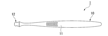
- FIG. 1 is a front view of the toothbrush 1 according to the present embodiment.
- FIG. 2 is a side view of the toothbrush 1.
- the toothbrush 1 includes a rod-shaped handle body 10 and a brush molded body 20.
- the handle body 10 and the brush molded body 20 are separate members.
- the brush molded body 20 can be detachably attached (inserted) to the handle body 10.
- the front surface in the present embodiment is the side on which the filament 23, which will be described later, protrudes from the normal direction (hereinafter, simply referred to as the normal direction) of the upper surface 21a (details will be described later) of the brush molded body 20.
- the length direction of the handle portion 11 and the direction in which the handle body 10 is inserted into the brush molded body 20 (hereinafter, simply referred to as the insertion direction) is orthogonal to the normal direction.
- the direction orthogonal to the normal direction and the insertion direction is the width direction of the brush molded body 20 (hereinafter, simply referred to as the width direction).
- FIG. 3 is a front view of the handle body 10.
- the handle body 10 includes a rod-shaped handle portion 11 and an insertion portion 12 provided at the tip of the handle portion 11 and projecting toward the tip end side of the handle portion 11 in the length direction. ..
- the insertion portion 12 of the handle body 10 is inserted into the brush molding body 20 described later, so that the insertion portion 12 is covered with the brush molding body 20 and attached.
- the front view shape of the handle portion 11 of the present embodiment is such that the width gradually narrows from the front end side to the rear end side and then extends at a constant width, and then gradually widens and then narrows. It changes in a curve.
- the front end of the handle portion 11 has a substantially semicircular shape at the rear end.
- the side view shape of the handle portion 11 extends from the front end side to the rear end side with a certain width, and then gradually widens to the maximum thickness of the finger rest portion.
- the side view shape of the handle portion 11 changes in a curve so that the width gradually narrows from the finger contact portion having the maximum thickness toward the rear end side.
- the side view shape of the handle portion 11 has a substantially semicircular shape at the rear end portion.
- the shape of the handle portion is not limited to the shape of this example, and can be appropriately set in consideration of strength, operability, design, and the like.
- the dimensions of the handle portion 11 are not particularly limited and can be set as appropriate.
- the length of the handle portion 11 can be 100 to 200 mm.
- the insertion portion 12 is a portion covered with the brush molded body 20 in a state where the brush molded body 20 is attached to the handle body 10.
- the rear end of the insertion portion 12 is the rear end position of the brush molded body 20 in a state where the brush molded body 20 is attached to the handle body 10.
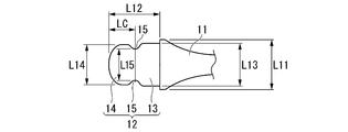
- FIG. 4 is an enlarged front view of the insertion portion 12.
- FIG. 5 is an enlarged side view of the insertion portion 12.
- the insertion portion 12 has a base portion 13 provided on the tip end side of the handle portion 11 and a tip portion 14 provided on the tip end of the base portion 13.
- the base portion 13 and the tip portion 14 have steps on both the front side and the back surface side with respect to the handle portion 11 and are formed to have the same thickness thinner than the handle portion 11.
- the base 13 has a substantially rectangular shape in a plan view.
- the base portion 13 has a step on both sides in the width direction with respect to the handle portion 11, and is formed with a width L13 narrower than the maximum width L11 on the tip end side of the handle portion 11 (L13 ⁇ L11).
- the tip portion 14 has a substantially elliptical shape in a plan view with the width direction as the major axis direction.
- the tip portion 14 has a substantially elliptical shape on both sides in the width direction, with side edges cut out in a straight line parallel to the insertion direction of the insertion portion 12.
- the tip portion 14 has a step on both sides in the width direction with respect to the base portion 13 and is formed with a width L14 narrower than the width L13 of the base portion 13.
- the insertion portion 12 is substantially in the center of the insertion direction, and has a recess 15 between the base portion 13 and the tip portion 14.
- the recesses 15 are provided on both sides in the width direction.
- the recess 15 has an arc shape having an arc center on the outside and a concave on the inside in the width direction.
- the shortest distance L15 between the recesses 15 is shorter than the width L13 of the base 13 and the width L14 of the tip 14.
- the amount of the recess 15 in the tip 14 with respect to the edge defining the width L14 is, for example, 1 mm.
- the position of the apex of the recess 15 recessed inward is within a range of 30% or more and 70% or less of the maximum length L12 of the insertion portion 12 in the insertion direction on the rear end side, starting from the tip of the insertion portion 12 in the insertion direction. It is preferably located, and more preferably located in the range of 40% or more and 60% or less. Further, the entire region forming the recess 15 is preferably located in the range of 30% or more and 70% or less of the maximum length L12, and more preferably located in the range of 40% or more and 60% or less (details are detailed. See below).
- the maximum depth of the recess 15 inward in the width direction is preferably 0.5 mm or more and 1.8 mm or less, preferably 0.8 mm or more and 1. It is more preferably 5 mm or less (details will be described later).
- the shape of the recess 15 it is possible to strengthen the fitting between the brush molded body 20 and the handle body 10.
- an arc shape is exemplified, but it may be a substantially rectangular shape, and a so-called burrs may be attached to the tip end side of the insertion portion of the dent 15.
- the maple has a shape in which the recessing direction of the recess 15 is not vertical toward the inside in the width direction but diagonally toward the handle portion 11.
- the recess 15 exemplifies a shape that is concave inward on both sides in the width direction of the insertion portion 12, it may be a shape that is convex outward.
- the handle body 10 is made of a hard resin.
- a resin having a flexural modulus (JIS K7171) of 1500 MPa or more and 3000 MPa or less can be exemplified.
- PP polypropylene resin
- POM polyacetal resin
- PCTA polyester resin
- PETG polyethylene terephthalate copolymer
- HDPE high-density polyethylene
- PP which is a general-purpose resin, is preferable in consideration of cost.
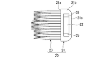
- FIG. 6 is a front view of the brush molded body 20.
- FIG. 7 is a cross-sectional view taken along the line AA in FIG.
- the brush molded body 20 includes a head base portion 21 having a substantially rectangular front view shape, and a plurality of filaments 23 provided on the front surface of the head base portion 21. There is.
- the filament 23 is a substantially columnar shape protruding from the upper surface 21a of the head base portion 21 to the front side.
- the filament 23 has a substantially triangular prism shape having a substantially triangular cross section on the base end side, and a triangular pyramid shape on the tip end side extending from the substantially triangular prism and tapering.
- the filament 23 As the tapered shape of the filament 23, a shape having one or more change points of the taper angle and having two change points of 0 to 2 mm and 4 to 8 mm from the tip can be exemplified. Further, the filament 23 may have a quadrangular pyramid shape. Even if the filament 23 has a quadrangular pyramid shape, it can be exemplified that the filament 23 has one or more change points of the taper angle and the change points are provided at two points of 0 to 2 mm and 4 to 8 mm from the tip. By adopting this configuration, it is possible to improve the cleanability while ensuring the moldability.
- the filament 23 is provided with a plurality of rows along the insertion direction so that the rows arranged along the width direction of the brush molded body 20 are offset by half a pitch from the adjacent rows in the insertion direction. That is, the filaments 23 are arranged in a staggered pattern.
- FIG. 8 is a view of the brush molded body 20 as viewed from the rear end side.
- the filament 23 has a high center in the width direction and a low outside in the width direction.
- the filament 23 may have a flat shape with no height difference in the width direction.
- the outer side in the direction may be higher, but when the dome shape has a higher center in the width direction, it is possible to further improve the cleanability in the oral cavity.
- the height difference of the filament is preferably 0.5 to 3.0 mm, more preferably 0.5 to 2.0 mm.
- the region where the central filament 23 is located (the width in the width direction of the filament base end (the maximum width of the region in the width direction where the filament base end is located)) is 20 to 45 of the length in the width direction occupied by the entire filament. It is preferably%, and more preferably 25 to 40%.
- the filament arrangement pitch is preferably 0.5 to 1.5 mm in both the length direction and the width direction, and more preferably 0.8 to 1.2 mm.
- the maximum length of the filament 23 is preferably 7 mm or more and 15 mm or less, and more preferably 9 mm or more and 13 mm or less. If the maximum length of the filament 23 is less than 7 mm, the cleanability in the oral cavity may be reduced. If the maximum length of the filament 23 exceeds 15 mm, the releasability when the brush molded body 20 is molded by injection molding is lowered. By setting the maximum length of the filament 23 to 7 mm or more and 15 mm or less, it is possible to secure the cleanability in the oral cavity and the releasability at the time of molding.
- the cross-sectional area of the base end of the filament 23 is preferably 0.8 mm 2 or less, more preferably 0.6 mm 2 or less, and further preferably 0.4 mm 2 or less.
- the cross-sectional area of the proximal end of the filament 23 exceeds 0.8 mm 2 , the filament 23 is less likely to bend, and there is a possibility that the cleanability of gaps between teeth and the cervical region may be reduced.
- the ratio of the total cross-sectional area of the base ends of the plurality of filaments 23 to the area of the upper surface 21a of the head base portion 21 is preferably 10% or more and 50% or less. If the ratio of the total cross-sectional area of the proximal end of the filament 23 is less than 10%, the cleanability in the oral cavity may be deteriorated. If the ratio of the total cross-sectional area of the base end of the filament 23 exceeds 50%, the releasability when the brush molded body 20 is molded by injection molding is lowered. By setting the ratio of the total cross-sectional area of the base end of the filament 23 to 10% or more and 50% or less, it is possible to secure the cleanability in the oral cavity and the releasability at the time of molding.
- a substantially polygonal shape such as a substantially quadrangle, a substantially circular shape, a substantially star shape, a substantially spatula shape, or the like can be selected.
- the filament 23 may have a tapered shape with a tapered tip, a straight extending structure, or a tapered shape with a tapered tip.
- the upper surface 21a of the head base portion 21 is a flat surface parallel to the width direction and the insertion direction.
- the upper surface 21a is flush with the position of the proximal end of the filament 23 with respect to the protruding direction of the filament 23.
- the upper surface 21a forms the outer contour (outermost circumference) of the head base portion 21. That is, the upper surface 21a is a parting surface for injection molding the brush molded body 20.
- the head base portion 21 has an insertion hole 22 that extends in the insertion direction and opens to the end surface 21b on the rear end side.
- FIG. 9 is a cross-sectional view of a plane parallel to the upper surface 21a including the insertion hole 22. As shown in FIG. 9, the insertion hole 22 has a first portion 33 that opens to the end surface 21b and a second portion 34 that is located behind the first portion 33. As shown in FIG. 7, the first portion 33 and the second portion 34 are formed to have the same thickness thinner than the head base portion 21.
- the head base portion 21 has a protrusion 35 located substantially in the center of the insertion hole 22 in the insertion direction and located between the first portion 33 and the second portion 34.
- the protrusions 35 are provided on both sides of the insertion hole 22 in the width direction.
- the protrusions 35 are provided at positions where the insertion portion 12 fits into the recess 15 when the insertion portion 12 is inserted into the insertion hole 22.
- the protrusion 35 has an arc shape having an arc center on the outside in the width direction and being convex inward.
- the maximum width L21 on the rear end side (end surface 21b) of the head base portion 21 is substantially the same as the maximum width L11 on the front end side of the handle portion 11.
- the front view shape of the insertion hole 22 is substantially the same as the front view shape of the insertion portion 12.
- the width L33 of the first portion 33 is a length into which the base portion 13 in the insertion portion 12 can be inserted, and is substantially the same as the maximum width L13 of the base portion 13.
- the width L34 of the second portion 34 is a length into which the tip portion 14 of the insertion portion 12 can be inserted, and is substantially the same as the maximum width L14 of the tip portion 14.
- the shortest distance L35 between the protrusions 35 is shorter than the width L33 of the first portion 33 and the width L34 of the second portion 34.
- the shortest distance L35 between the protrusions 35 is a length into which the tip portion 14 and the recess 15 in the insertion portion 12 can be inserted, and is substantially the same as the shortest distance L15 between the recesses 15.
- the amount of protrusion of the protrusion 35 inward in the width direction with respect to the second portion 34 is, for example, 1 mm.
- the amount of protrusion of the protrusion 35 with respect to the second portion 34 is the amount of undercut when the mold (slide core) for forming the insertion hole 22 is pulled out to the rear end side during injection molding of the brush molded body 20.
- the maximum distance (maximum thickness) T between the upper surface 21a of the head base portion 21 and the second surface 21c on the back surface side is preferably 2.0 mm or more and 4.5 mm or less.
- the maximum distance T is less than 2.0 mm, the gap between the upper surface 21a and the surface of the insertion hole 22 on the upper surface 21a side, or between the second surface 21c and the surface of the insertion hole 22 on the second surface 21c side. Since the gap between the two is reduced and the fluidity of the molten resin is reduced during molding, the resin may be unfilled.
- the maximum distance T exceeds 4.5 mm, the operability when the brush molded body 20 is inserted into the oral cavity may decrease.
- the distance (maximum length) in the width direction of the head base portion 21 is not particularly limited, but is, for example, 10 to 16 mm. In particular, when the maximum length of the head base portion 21 in the width direction is 13 to 16 mm, the operability in the oral cavity can be ensured by making the head portion thin even though the head is wide.
- the height t1 of the insertion hole 22 is preferably 1.0 mm or more and 2.5 mm or less.
- the thickness (distance) t2 of the head base portion 21 between the upper surface 21a and the surface of the insertion hole 22 on the upper surface 21a side is preferably 0.5 mm or more and 2.0 mm or less.
- the thickness (distance) t3 of the head base portion 21 between the second surface 21c on the back surface side of the head base portion 21 and the surface on the second surface 21c side of the insertion hole 22 is 0.5 mm or more. It is preferably 0 mm or less.
- the maximum length of the head base portion 21 in the insertion direction is L1 and the maximum length of the insertion hole 22 in the insertion direction is L2, the maximum length of the head base portion 21 represented by L2 / L1.
- the ratio of the maximum length L2 of the insertion hole 22 to L1 is preferably 0.30 or more and 0.70 or less, more preferably 0.40 or more and 0.60 or less, and 0.45 or more. It is more preferably 0.55 or less.
- the distance between the tip end of the insertion hole 22 and the tip end of the head base 21 represented by L1-L2 is preferably 5 mm or more and 15 mm or less, preferably 8 mm or more. It is more preferably 12 mm or less.
- the resin flow is restricted, so that the moldability of the filament 23 is lowered.
- the value represented by L1-L2 exceeds 15 mm, the region where the insertion portion 12 formed of the hard resin does not exist becomes large, so that the front surface of the brush molded body 20 tends to bend, and usability may decrease. There is sex.
- the minimum distance S between the base end of the filament 23 located on the most distal end side and the back surface of the head base portion 21 is preferably 1.5 mm or more and 3.0 mm or less.
- the minimum thickness of the head base portion 21 is preferably 1.0 to 2.5 mm. By setting the minimum thickness of the head base portion 21 to this range, it is possible to improve the operability in the oral cavity while reducing the discomfort when the tip of the head portion comes into contact with the oral tissue.
- the insertion hole 22 (that is, the insertion hole 22 is formed) on the tip side of the insertion hole 22 in the brush molded body 20.
- the resin can flow in the region where the slide core for molding the insertion hole 22 does not exist in the mold, so that the obstacle of the resin fluidity due to the presence of the slide core is suppressed and the filament 23 is molded. Sex improves.
- the gate position for filling the resin into the mold can be selected, for example, the tip of the head base portion 21, but is not particularly limited.
- the gate position can be arranged, for example, on the back surface or the rear end of the head base portion 21, and it is possible to avoid a problem that the uncut portion (gate mark) of the gate cut damages the oral tissue.
- a recess 35M (see FIG. 10) for forming the protrusion 35 to be fitted in the recess 15 is formed in the slide core in the normal direction. Will be.
- the recess 35M constitutes a resin flow flow path connecting the back side to the front side of the slide core in which the insertion hole 22 is molded in the mold at the time of molding. Normally, the resin flow is restricted in the region occupied by the slide core, but the moldability of the filament 23 is improved by securing the recess 35M for molding the protrusion 35 as the flow path of the resin flow.
- the recess 15 is 30% or more and 70% or less of the maximum length L12 of the insertion portion 12 in the insertion direction on the rear end side, starting from the tip in the insertion direction of the insertion portion 12.
- the recess 35M of the slide core for forming the protrusion 35 is located near the center of the insertion hole 22 in the insertion direction. If the position of the protrusion 35 is outside the above range in the insertion direction of the insertion portion 12, the resin flow during molding may be biased and the filament 23 may not be uniformly molded. By setting the position of the protrusion 35 within the above range in the insertion direction of the insertion portion 12, the bias of the resin flow is suppressed and the filament 23 can be uniformly molded.
- the maximum depth of the recess 15 (projection 35) inward in the width direction is preferably 0.5 mm or more and 1.8 mm or less (0.8 mm or more, 1.5 mm or less). Is more preferable).
- the maximum depth of the recess 15 inward in the width direction is less than 0.5 mm, the recess 35M is formed only on the edge of the slide core, so that a large improvement in resin fluidity cannot be expected and the fitting with the protrusion 35 cannot be expected. There is a possibility that the brush molded body 20 will fall off when the toothbrush 1 is used due to the weakening of the resin.
- the fitting (undercut amount) with the protrusion 35 becomes large, and the insertion portion 12 may break at the time of mold release.
- the maximum depth of the recess 15 inward in the width direction to 0.5 mm or more and 1.8 mm or less, it is possible to improve the resin fluidity, prevent the brush molded body 20 from falling off, and prevent the insertion portion 12 from breaking. it can.
- the handle body 10 has a brush on the tip end side of the insertion portion of the recess 15, the fitting between the brush molded body 20 and the handle body 10 can be further strengthened.
- the head base portion 21 has a thin-walled region 21d in which the tip end side of the back surface 21c gradually inclines toward the front end side and gradually becomes thinner toward the tip end side.
- the maximum length L3 of the thin-walled region 21d in the insertion direction is preferably 40% or more, preferably 50% or more of the maximum length L1 of the head base portion 21 in the insertion direction. More preferred.
- the maximum length L3 of the thin region 21d By setting the maximum length L3 of the thin region 21d to 40% or more of the maximum length L1 of the head base portion 21, the volume on the back surface side of the brush molded body 20 can be reduced, so that the molten resin is placed on the upper surface 21a side during molding. Can be preferentially flowed, and the moldability of the filament 23 can be improved. This effect becomes more remarkable when the gate position is arranged at the tip of the head base portion 21.
- the maximum length L3 of the thin region 21d is less than 40% of the maximum length L1 of the head base portion 21, the improvement in moldability may be diluted.
- polyurethane As the soft resin constituting the brush molded body 20, various elastomers can be used, but polyurethane is preferable. Polyurethane tends to have higher tensile strength than other elastomers such as styrene-based and polyester-based elastomers. Therefore, by using polyurethane as the soft resin, mechanical strength can be secured even if the thickness is thin, and the insertion portion 12 It is possible to suppress damage when the toothbrush is fitted with the insertion hole 22 and when the toothbrush 1 is used.
- polyurethane 0.01-1.0 wt% (mass%) of saturated / unsaturated hydrocarbons of C10 or more, higher alcohols, fatty acid amides, fatty acid ester low molecular weight polyethylene, polyethylene glycol (PEG), fatty acid metal salts, etc. It functions as a lubricant or a mold release agent when it is blended with any one of long-chain fatty acids, fatty acid glycerin, and silicone, or in combination.
- polyurethane has a wide range of hardness that can be selected as compared with the other elastomers described above, and the resin hardness can be selected in consideration of its usability (for example, bending of the tip of the brush molded body) according to the thickness of the brush molded body 20. It is possible.
- the hardness of the polyurethane is preferably shore 90A or more and 70D or less. If the hardness of the polyurethane is softer than that of the shore 90A, it is likely to be deformed when it is formed of a thin wall, so that the fitting is weakened and the brush molded body 20 is likely to fall off when the toothbrush 1 is used.
- the hardness of the polyurethane is harder than the shore 70D, pain may occur when the tip hits the oral tissue when the back surface of the head base 21 is tilted.
- shore 90A or more and 70D or less it is possible to prevent the brush molded body 20 from falling off when the toothbrush 1 is used, or to prevent pain when the tip of the head base portion 21 hits.
- polyurethane it is preferable to use an ether-based polyurethane from the viewpoint of ensuring water resistance and antibacterial properties.
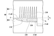
- FIG. 10 is a cross-sectional view briefly showing an example of a mold MD for molding the brush molded body 20.
- FIG. 11 is a cross-sectional view briefly showing the mold MD before mold clamping.
- the mold MD includes a first mold MD1 and a second mold MD2 that move relative to each other in the opening / closing direction (vertical direction in FIG. 10).
- the first mold MD1 and the second mold MD2 are molded with the parting surface PL flush with the upper surface 21a as a joint surface.
- the first mold MD1 is attached to, for example, the fixed side of an injection molding machine, and the molten resin is filled from the injection molding machine.
- the second mold MD2 is attached to, for example, the movable side of the injection molding machine, and by moving in the opening / closing direction with respect to the first mold MD1, the mold MD is also opened / closed.
- the first mold MD1 has a molding surface 21aM on which the upper surface 21a is molded and a cavity 23M on which the filament 23 is molded when the mold is compacted and joined to the second mold MD2.
- the second mold MD2 has a cavity 21M in which the head base portion 21 is formed when the mold is compacted and joined to the first mold MD1, and the cavity 21M is opened to the tip side, and molten resin is introduced into the cavity 21M. It has a gate portion G to be formed and a contact surface 21eM provided at a position of an end surface 21b in the insertion direction and orthogonal to the insertion direction.
- a gate portion G for example, a side gate method is used, but a pinpoint gate method or a tunnel gate method may be used.
- the contact surface 21eM extends in the direction away from the PL surface from the position where the back surface of the head base portion 21 is formed in the second mold MD2.
- the second mold MD is provided with a slide core SL.
- the slide core SL has a core portion 22M in which the insertion hole 22 is formed, and a molding surface 21bM in which the core portion 22M protrudes and is orthogonal to the insertion direction. As shown in FIG. 11, the molding surface 21bM is separated from the contact surface 21eM before mold clamping.
- the first mold MD1 and the second mold MD2 are molded, a part of the molding surface 21bM comes into contact with the contact surface 21eM as shown in FIG. 10, and the core portion 22M Is positioned at the position where it is inserted into the cavity 21M.
- the region facing the cavity 21M without contacting the contact surface 21eM is a region for molding the end surface 21b.
- the slide core SL has a core so that the core portion 22M does not interfere with the release of the molded brush molded body 20 when the first mold MD1 and the second mold MD2 are opened.
- the portion 22M moves in a direction away from the cavity 21M.
- the movement direction of the slide core SL is preferably horizontal in order to avoid unexpected movement due to its own weight.
- the configuration of the mold MD illustrates that the insertion hole 22 of the brush molded body 20 is formed by the slide core SL, but the handle body 10 is inserted into the mold MD and the brush molded body 20 is secondarily molded. You can also choose the method. In that case, it is disadvantageous to make the brush molded body 20 and the handle body 10 detachable, but the post-step of fitting the handle body 10 and the brush molded body 20 after molding can be omitted.
- the dimensions of the R chamfering process and the C chamfering process are preferably 1.5 mm or more, and more preferably 3.0 mm or more.
- the molten resin introduced into the cavity 21M from the gate portion G in a state where the first mold MD1 and the second mold MD2 are molded is on the tip side of the core portion 22M in the cavity 21M. Due to the fact that a sufficient volume is secured and the back surface side of the cavity 21M is inclined and thinned, the molten resin introduced into the tip side of the cavity 21M flows preferentially to the upper surface 21a side.
- the cavity 23M can be filled with the molten resin with sufficient filling pressure.
- the molten resin introduced into the back side of the core portion 22M can flow to the front side using the recess 35M formed near the center of the core portion 22M in the insertion direction as a flow path. It is possible to uniformly mold the filament 23 in a state where the bias of the resin flow is suppressed in the direction.
- the resin flows even when the thickness of the head base portion 21 is reduced to 2.0 mm or more and 4.5 mm or less by using the brush molded body 20 having a fitting structure. It is possible to provide a toothbrush 1 having excellent intraoral operability by molding the brush molded body 20 without deteriorating the properties.
- the maximum distance T between the base end of the filament and the back surface of the head base portion is 2.0 mm or more and 4.5 mm or less, and the maximum length L1 of the head base portion is 1.
- L2 / L1 which is the ratio of the maximum length L2 of the insertion hole to the above is 0.30 or more and 0.70 or less, the moldability of the filament, the difficulty of bending the brush molded body, and the like. Good results were obtained in all of the ease of polishing the entire oral cavity.
- Comparative Example 1 in which L2 / L1, which is the ratio of the maximum length L2 of the insertion hole to the maximum length L1 of the head base portion, is less than 0.30, the brush molded body is bent. Good results were not obtained regarding the texture. Further, in Comparative Example 2 in which L2 / L1, which is the ratio of the maximum length L2 of the insertion hole to the maximum length L1 of the head base portion exceeds 0.70, good results regarding the moldability of the filament were obtained. There wasn't.
- the center position LC of the recess with the tip of the insertion portion as the base point is less than 3 mm, which is the ratio of the position LC of the recess to the maximum length L12 (maximum length L2 of the insertion hole) of the insertion portion 12 in the insertion direction.
- the ratio of / L12 (LC / L2) is less than 30%
- the center position LC of the recess with the tip of the insertion portion as the base point exceeds 7 mm, and the maximum length L12 (insertion) of the insertion portion 12 in the insertion direction.
- Example 7 in which the ratio of LC / L12 (LC / L2), which is the ratio of the position LC of the recess to the maximum hole length L2), is 70% or more, the moldability of the filament is as good as that of Example 1. No results were obtained.
- Comparative Example 1 in which the difference between the maximum length L1 of the head base portion and the maximum length L2 of the insertion hole, which is represented by L1-L2, exceeds 15 mm, regarding the difficulty of bending the brush molded body. In addition to the fact that good results were not obtained, the results were not as good as in Example 1 regarding the ease of polishing the entire oral cavity.
- the upper surface 21a forming the outer contour (outermost circumference) of the head base portion 21 and the base end of the filament 23 are flush with each other, and the filament 23 projects from the upper surface 21a.
- the upper surface 21a is provided with a base portion that is located inside the outer contour of the head base portion 21 and protrudes from the upper surface 21a with a certain thickness, and the filament 23 protrudes from the upper surface of the base portion instead of the upper surface 21a (.
- the upper surface of the base portion and the base end of the filament 23 are flush with each other).
- the brush molded body 20 becomes thicker by the thickness of the base portion, it is preferable that the upper surface 21a serving as the parting surface PL and the base end of the filament 23 are flush with each other.
- the fluidity of the resin is lower than that when the base portion is provided, so that the action of the present invention becomes more remarkable.
- the configuration in which the handle body 10 is formed of a hard resin is illustrated, but the present invention is not limited to this configuration, and for example, a part of the handle body 10 (handle portion 10, etc.) is coated with a soft resin. It may have a different configuration. When this configuration is adopted, the decorativeness and grip can be improved.
- the present invention can be applied to a toothbrush.
Landscapes
- Chemical & Material Sciences (AREA)
- Health & Medical Sciences (AREA)
- Chemical Kinetics & Catalysis (AREA)
- Medicinal Chemistry (AREA)
- Polymers & Plastics (AREA)
- Organic Chemistry (AREA)
- Engineering & Computer Science (AREA)
- Materials Engineering (AREA)
- Brushes (AREA)
Priority Applications (6)
| Application Number | Priority Date | Filing Date | Title |
|---|---|---|---|
| CN202410610365.XA CN118356050A (zh) | 2019-12-23 | 2020-12-01 | 牙刷 |
| EP20905298.4A EP4082388A4 (en) | 2019-12-23 | 2020-12-01 | TOOTHBRUSH |
| KR1020227017246A KR20220120557A (ko) | 2019-12-23 | 2020-12-01 | 칫솔 |
| CN202080079989.3A CN114760881B (zh) | 2019-12-23 | 2020-12-01 | 牙刷 |
| US17/777,548 US20220400843A1 (en) | 2019-12-23 | 2020-12-01 | Toothbrush |
| JP2021567110A JP7607587B2 (ja) | 2019-12-23 | 2020-12-01 | 歯ブラシ |
Applications Claiming Priority (2)
| Application Number | Priority Date | Filing Date | Title |
|---|---|---|---|
| JP2019-231982 | 2019-12-23 | ||
| JP2019231982 | 2019-12-23 |
Publications (1)
| Publication Number | Publication Date |
|---|---|
| WO2021131526A1 true WO2021131526A1 (ja) | 2021-07-01 |
Family
ID=76573894
Family Applications (1)
| Application Number | Title | Priority Date | Filing Date |
|---|---|---|---|
| PCT/JP2020/044628 Ceased WO2021131526A1 (ja) | 2019-12-23 | 2020-12-01 | 歯ブラシ |
Country Status (7)
| Country | Link |
|---|---|
| US (1) | US20220400843A1 (https=) |
| EP (1) | EP4082388A4 (https=) |
| JP (1) | JP7607587B2 (https=) |
| KR (1) | KR20220120557A (https=) |
| CN (3) | CN118356050A (https=) |
| TW (1) | TWI867103B (https=) |
| WO (1) | WO2021131526A1 (https=) |
Cited By (8)
| Publication number | Priority date | Publication date | Assignee | Title |
|---|---|---|---|---|
| US20220400843A1 (en) * | 2019-12-23 | 2022-12-22 | Lion Corporation | Toothbrush |
| WO2023120211A1 (ja) * | 2021-12-20 | 2023-06-29 | ライオン株式会社 | ブラシ成形体および歯ブラシ |
| WO2023120163A1 (ja) * | 2021-12-22 | 2023-06-29 | ライオン株式会社 | ブラシ成形体および歯ブラシ |
| JP2023093930A (ja) * | 2021-12-23 | 2023-07-05 | サンスター株式会社 | 歯ブラシ |
| WO2024135197A1 (ja) * | 2022-12-22 | 2024-06-27 | ライオン株式会社 | 歯ブラシ |
| WO2024142753A1 (ja) * | 2022-12-27 | 2024-07-04 | ライオン株式会社 | ブラシ成形体および歯ブラシ |
| WO2024142677A1 (ja) * | 2022-12-27 | 2024-07-04 | ライオン株式会社 | 歯ブラシ |
| JPWO2025070016A1 (https=) * | 2023-09-26 | 2025-04-03 |
Families Citing this family (3)
| Publication number | Priority date | Publication date | Assignee | Title |
|---|---|---|---|---|
| US11877645B2 (en) | 2021-05-14 | 2024-01-23 | Colgate-Palmolive Company | Personal care implement |
| USD1029506S1 (en) * | 2021-12-30 | 2024-06-04 | Colgate-Palmolive Company | Toothbrush |
| USD1090056S1 (en) * | 2022-09-06 | 2025-08-26 | Smile Makers, Llc | Tongue cleaning device |
Citations (8)
| Publication number | Priority date | Publication date | Assignee | Title |
|---|---|---|---|---|
| JPS61207233U (https=) | 1985-06-14 | 1986-12-27 | ||
| WO1997015995A1 (en) * | 1995-07-25 | 1997-05-01 | The Research Foundation Of State University Of New York | Method and apparatus of assigning and sharing channels in a cellular communication system |
| WO2000049911A1 (en) * | 1999-02-24 | 2000-08-31 | Susumu Inoue | Rubber-nylon-mixture bristle toothbrush |
| JP2003153741A (ja) * | 2001-11-22 | 2003-05-27 | Matsushita Electric Works Ltd | 歯茎マッサージ用ブラシおよび歯茎マッサージ装置 |
| JP2010194044A (ja) * | 2009-02-24 | 2010-09-09 | Sunstar Inc | 歯ブラシ及びその製造方法 |
| CN204561298U (zh) | 2015-04-24 | 2015-08-19 | 郑超 | 一种环保三棱锥体刷毛清洁舌苔一体成型牙刷头 |
| CN107041792A (zh) | 2017-02-08 | 2017-08-15 | 河源唯缇科技有限公司 | 一种套接式刷毛套牙刷装置 |
| WO2017155039A1 (ja) * | 2016-03-09 | 2017-09-14 | ライオン株式会社 | 歯ブラシ |
Family Cites Families (24)
| Publication number | Priority date | Publication date | Assignee | Title |
|---|---|---|---|---|
| JPS61207233A (ja) | 1985-03-13 | 1986-09-13 | Kubota Ltd | 走行装置 |
| FR2654597B1 (fr) * | 1989-11-21 | 1992-02-21 | Beltramo Philippe | Brosse a dent a tetes interchangeables. |
| US5369831A (en) * | 1991-03-25 | 1994-12-06 | Sonex International Corporation | Therapeutic ultrasonic toothbrush |
| DE4136537C1 (https=) * | 1991-11-06 | 1993-01-21 | Johnson & Johnson Ag, Spreitenbach, Ch | |
| US20020112302A1 (en) * | 1994-09-16 | 2002-08-22 | Susan Harrison | Child's utensil |
| US5987688A (en) * | 1995-11-09 | 1999-11-23 | Gillette Canada Inc. | Gum-massaging oral brush |
| JP2002291534A (ja) * | 2001-04-03 | 2002-10-08 | Temuko Kk | 歯ブラシ |
| JP2003144228A (ja) * | 2001-11-13 | 2003-05-20 | Asahi Irika Kk | ブラシ部分が交換可能な歯ブラシ |
| JP4146729B2 (ja) * | 2002-05-27 | 2008-09-10 | テムコ株式会社 | 歯ブラシ |
| KR200299445Y1 (ko) * | 2002-09-18 | 2003-01-06 | 정창구 | 칫솔 |
| JP4628956B2 (ja) * | 2003-10-29 | 2011-02-09 | ライオン株式会社 | 歯ブラシ |
| KR200364176Y1 (ko) * | 2004-07-09 | 2004-10-08 | 방선오 | 아래위로 닦기가 편리한 가로형 칫솔 |
| JP5993555B2 (ja) * | 2011-08-09 | 2016-09-14 | ライオン株式会社 | 歯ブラシ |
| KR102577531B1 (ko) * | 2014-09-01 | 2023-09-12 | 라이온 가부시키가이샤 | 칫솔 |
| KR101804482B1 (ko) * | 2016-03-24 | 2017-12-04 | 김재찬 | 칫솔모 헤드 교체 가능한 칫솔 |
| JP2017176219A (ja) * | 2016-03-28 | 2017-10-05 | ライオン株式会社 | 歯ブラシのハンドル体および歯ブラシ |
| JP6711106B2 (ja) * | 2016-04-22 | 2020-06-17 | オムロンヘルスケア株式会社 | 歯ブラシ |
| JP2018033510A (ja) | 2016-08-29 | 2018-03-08 | ライオン株式会社 | 歯ブラシの製造方法 |
| CN108158195A (zh) * | 2016-12-07 | 2018-06-15 | 陈德谦 | 旋转牙刷 |
| KR102126524B1 (ko) * | 2019-09-02 | 2020-06-24 | 이단열 | 기능성 칫솔패드와 교체 가능한 u자형 칫솔모헤드가 장착된 칫솔 |
| US20220400843A1 (en) * | 2019-12-23 | 2022-12-22 | Lion Corporation | Toothbrush |
| KR102176455B1 (ko) * | 2020-02-04 | 2020-11-09 | 김은진 | 기능성 칫솔 |
| DE102020105351A1 (de) * | 2020-02-28 | 2021-09-02 | Zahoransky Ag | Zahnbürstenkopf, Zahnbürste, Verfahren zur Herstellung eines Zahnbürstenkopfes, Verfahren zur Herstellung einer Zahnbürste, additive Fertigungsvorrichtung, Computerprogramm und computerlesbares Medium |
| KR102194701B1 (ko) * | 2020-03-30 | 2020-12-23 | 이단열 | 칫솔본체에 교체 가능한 도브테일형 칫솔모헤드가 장착된 칫솔 |
-
2020
- 2020-12-01 US US17/777,548 patent/US20220400843A1/en active Pending
- 2020-12-01 EP EP20905298.4A patent/EP4082388A4/en active Pending
- 2020-12-01 KR KR1020227017246A patent/KR20220120557A/ko active Pending
- 2020-12-01 JP JP2021567110A patent/JP7607587B2/ja active Active
- 2020-12-01 CN CN202410610365.XA patent/CN118356050A/zh active Pending
- 2020-12-01 CN CN202080079989.3A patent/CN114760881B/zh active Active
- 2020-12-01 WO PCT/JP2020/044628 patent/WO2021131526A1/ja not_active Ceased
- 2020-12-02 TW TW109142422A patent/TWI867103B/zh active
- 2020-12-21 CN CN202023095842.XU patent/CN216255954U/zh active Active
Patent Citations (8)
| Publication number | Priority date | Publication date | Assignee | Title |
|---|---|---|---|---|
| JPS61207233U (https=) | 1985-06-14 | 1986-12-27 | ||
| WO1997015995A1 (en) * | 1995-07-25 | 1997-05-01 | The Research Foundation Of State University Of New York | Method and apparatus of assigning and sharing channels in a cellular communication system |
| WO2000049911A1 (en) * | 1999-02-24 | 2000-08-31 | Susumu Inoue | Rubber-nylon-mixture bristle toothbrush |
| JP2003153741A (ja) * | 2001-11-22 | 2003-05-27 | Matsushita Electric Works Ltd | 歯茎マッサージ用ブラシおよび歯茎マッサージ装置 |
| JP2010194044A (ja) * | 2009-02-24 | 2010-09-09 | Sunstar Inc | 歯ブラシ及びその製造方法 |
| CN204561298U (zh) | 2015-04-24 | 2015-08-19 | 郑超 | 一种环保三棱锥体刷毛清洁舌苔一体成型牙刷头 |
| WO2017155039A1 (ja) * | 2016-03-09 | 2017-09-14 | ライオン株式会社 | 歯ブラシ |
| CN107041792A (zh) | 2017-02-08 | 2017-08-15 | 河源唯缇科技有限公司 | 一种套接式刷毛套牙刷装置 |
Non-Patent Citations (1)
| Title |
|---|
| See also references of EP4082388A4 |
Cited By (11)
| Publication number | Priority date | Publication date | Assignee | Title |
|---|---|---|---|---|
| US20220400843A1 (en) * | 2019-12-23 | 2022-12-22 | Lion Corporation | Toothbrush |
| WO2023120211A1 (ja) * | 2021-12-20 | 2023-06-29 | ライオン株式会社 | ブラシ成形体および歯ブラシ |
| JP2023091379A (ja) * | 2021-12-20 | 2023-06-30 | ライオン株式会社 | ブラシ成形体および歯ブラシ |
| JP7617835B2 (ja) | 2021-12-20 | 2025-01-20 | ライオン株式会社 | ブラシ成形体および歯ブラシ |
| WO2023120163A1 (ja) * | 2021-12-22 | 2023-06-29 | ライオン株式会社 | ブラシ成形体および歯ブラシ |
| JP2023093930A (ja) * | 2021-12-23 | 2023-07-05 | サンスター株式会社 | 歯ブラシ |
| WO2024135197A1 (ja) * | 2022-12-22 | 2024-06-27 | ライオン株式会社 | 歯ブラシ |
| WO2024142753A1 (ja) * | 2022-12-27 | 2024-07-04 | ライオン株式会社 | ブラシ成形体および歯ブラシ |
| WO2024142677A1 (ja) * | 2022-12-27 | 2024-07-04 | ライオン株式会社 | 歯ブラシ |
| JPWO2025070016A1 (https=) * | 2023-09-26 | 2025-04-03 | ||
| WO2025070016A1 (ja) * | 2023-09-26 | 2025-04-03 | ライオン株式会社 | 歯ブラシ |
Also Published As
| Publication number | Publication date |
|---|---|
| CN118356050A (zh) | 2024-07-19 |
| TWI867103B (zh) | 2024-12-21 |
| CN114760881B (zh) | 2024-06-07 |
| CN114760881A (zh) | 2022-07-15 |
| US20220400843A1 (en) | 2022-12-22 |
| TW202123845A (zh) | 2021-07-01 |
| JPWO2021131526A1 (https=) | 2021-07-01 |
| JP7607587B2 (ja) | 2024-12-27 |
| EP4082388A4 (en) | 2024-01-10 |
| KR20220120557A (ko) | 2022-08-30 |
| EP4082388A1 (en) | 2022-11-02 |
| CN216255954U (zh) | 2022-04-12 |
Similar Documents
| Publication | Publication Date | Title |
|---|---|---|
| WO2021131526A1 (ja) | 歯ブラシ | |
| JP5530776B2 (ja) | 歯ブラシ | |
| CN103957744B (zh) | 牙刷 | |
| JP6868557B2 (ja) | 歯ブラシ | |
| WO2016158526A1 (ja) | 歯ブラシ | |
| WO2018079115A1 (ja) | 歯ブラシ | |
| KR20240006495A (ko) | 칫솔 | |
| JP6906313B2 (ja) | 歯ブラシ | |
| TWI906438B (zh) | 刷毛成形體以及牙刷 | |
| JP7617835B2 (ja) | ブラシ成形体および歯ブラシ | |
| JP7292031B2 (ja) | 歯間ブラシ | |
| JP7407091B2 (ja) | 歯ブラシ | |
| WO2024135197A1 (ja) | 歯ブラシ | |
| WO2024142753A1 (ja) | ブラシ成形体および歯ブラシ | |
| WO2021131553A1 (ja) | 歯ブラシ | |
| WO2024142677A1 (ja) | 歯ブラシ | |
| CN223008635U (zh) | 牙刷 | |
| JP7638227B2 (ja) | 歯ブラシ |
Legal Events
| Date | Code | Title | Description |
|---|---|---|---|
| 121 | Ep: the epo has been informed by wipo that ep was designated in this application |
Ref document number: 20905298 Country of ref document: EP Kind code of ref document: A1 |
|
| ENP | Entry into the national phase |
Ref document number: 2021567110 Country of ref document: JP Kind code of ref document: A |
|
| NENP | Non-entry into the national phase |
Ref country code: DE |
|
| ENP | Entry into the national phase |
Ref document number: 2020905298 Country of ref document: EP Effective date: 20220725 |