WO2021131526A1 - Toothbrush - Google Patents
Toothbrush Download PDFInfo
- Publication number
- WO2021131526A1 WO2021131526A1 PCT/JP2020/044628 JP2020044628W WO2021131526A1 WO 2021131526 A1 WO2021131526 A1 WO 2021131526A1 JP 2020044628 W JP2020044628 W JP 2020044628W WO 2021131526 A1 WO2021131526 A1 WO 2021131526A1
- Authority
- WO
- WIPO (PCT)
- Prior art keywords
- head base
- filament
- maximum length
- base portion
- less
- Prior art date
Links
- 238000003780 insertion Methods 0.000 claims abstract description 162
- 230000037431 insertion Effects 0.000 claims abstract description 162
- 229920005989 resin Polymers 0.000 claims abstract description 58
- 239000011347 resin Substances 0.000 claims abstract description 58
- 229920002635 polyurethane Polymers 0.000 claims description 14
- 239000004814 polyurethane Substances 0.000 claims description 14
- 210000003128 head Anatomy 0.000 abstract description 71
- 238000000465 moulding Methods 0.000 abstract description 31
- 210000000214 mouth Anatomy 0.000 abstract description 16
- 238000011156 evaluation Methods 0.000 description 11
- 238000001746 injection moulding Methods 0.000 description 8
- 238000000034 method Methods 0.000 description 7
- 238000005452 bending Methods 0.000 description 6
- 230000000052 comparative effect Effects 0.000 description 6
- 238000013461 design Methods 0.000 description 5
- 230000001680 brushing effect Effects 0.000 description 4
- 230000008859 change Effects 0.000 description 4
- 235000014113 dietary fatty acids Nutrition 0.000 description 4
- 229920001971 elastomer Polymers 0.000 description 4
- 239000000806 elastomer Substances 0.000 description 4
- 229930195729 fatty acid Natural products 0.000 description 4
- 239000000194 fatty acid Substances 0.000 description 4
- 238000005498 polishing Methods 0.000 description 4
- -1 polypropylene Polymers 0.000 description 4
- 239000004743 Polypropylene Substances 0.000 description 3
- 150000004665 fatty acids Chemical class 0.000 description 3
- RTZKZFJDLAIYFH-UHFFFAOYSA-N Diethyl ether Chemical compound CCOCC RTZKZFJDLAIYFH-UHFFFAOYSA-N 0.000 description 2
- PEDCQBHIVMGVHV-UHFFFAOYSA-N Glycerine Chemical compound OCC(O)CO PEDCQBHIVMGVHV-UHFFFAOYSA-N 0.000 description 2
- 239000002202 Polyethylene glycol Substances 0.000 description 2
- PPBRXRYQALVLMV-UHFFFAOYSA-N Styrene Chemical compound C=CC1=CC=CC=C1 PPBRXRYQALVLMV-UHFFFAOYSA-N 0.000 description 2
- 229920001903 high density polyethylene Polymers 0.000 description 2
- 239000004700 high-density polyethylene Substances 0.000 description 2
- 230000006872 improvement Effects 0.000 description 2
- 229920001223 polyethylene glycol Polymers 0.000 description 2
- 229920006324 polyoxymethylene Polymers 0.000 description 2
- 230000008569 process Effects 0.000 description 2
- 238000012545 processing Methods 0.000 description 2
- 230000001953 sensory effect Effects 0.000 description 2
- 241000208140 Acer Species 0.000 description 1
- 229930182556 Polyacetal Natural products 0.000 description 1
- 239000004698 Polyethylene Substances 0.000 description 1
- 230000009471 action Effects 0.000 description 1
- 150000001298 alcohols Chemical class 0.000 description 1
- 230000000844 anti-bacterial effect Effects 0.000 description 1
- 230000008901 benefit Effects 0.000 description 1
- 238000004140 cleaning Methods 0.000 description 1
- 238000005056 compaction Methods 0.000 description 1
- 239000000470 constituent Substances 0.000 description 1
- 230000007547 defect Effects 0.000 description 1
- 230000006866 deterioration Effects 0.000 description 1
- 230000002542 deteriorative effect Effects 0.000 description 1
- 230000000694 effects Effects 0.000 description 1
- 235000011187 glycerol Nutrition 0.000 description 1
- 150000004668 long chain fatty acids Chemical class 0.000 description 1
- 239000000314 lubricant Substances 0.000 description 1
- 239000000463 material Substances 0.000 description 1
- 239000002184 metal Substances 0.000 description 1
- 239000006082 mold release agent Substances 0.000 description 1
- 229920000728 polyester Polymers 0.000 description 1
- 229920001225 polyester resin Polymers 0.000 description 1
- 239000004645 polyester resin Substances 0.000 description 1
- 229920000573 polyethylene Polymers 0.000 description 1
- 229920000139 polyethylene terephthalate Polymers 0.000 description 1
- 239000005020 polyethylene terephthalate Substances 0.000 description 1
- 229920005644 polyethylene terephthalate glycol copolymer Polymers 0.000 description 1
- 229920001155 polypropylene Polymers 0.000 description 1
- 229920001296 polysiloxane Polymers 0.000 description 1
- 150000003839 salts Chemical class 0.000 description 1
- 229920006395 saturated elastomer Polymers 0.000 description 1
- 229930195734 saturated hydrocarbon Natural products 0.000 description 1
- 238000010408 sweeping Methods 0.000 description 1
- 229930195735 unsaturated hydrocarbon Natural products 0.000 description 1
- XLYOFNOQVPJJNP-UHFFFAOYSA-N water Substances O XLYOFNOQVPJJNP-UHFFFAOYSA-N 0.000 description 1
- 230000003313 weakening effect Effects 0.000 description 1
Images


Classifications
-
- A—HUMAN NECESSITIES
- A46—BRUSHWARE
- A46B—BRUSHES
- A46B1/00—Brush bodies and bristles moulded as a unit
-
- C—CHEMISTRY; METALLURGY
- C08—ORGANIC MACROMOLECULAR COMPOUNDS; THEIR PREPARATION OR CHEMICAL WORKING-UP; COMPOSITIONS BASED THEREON
- C08L—COMPOSITIONS OF MACROMOLECULAR COMPOUNDS
- C08L75/00—Compositions of polyureas or polyurethanes; Compositions of derivatives of such polymers
- C08L75/04—Polyurethanes
-
- A—HUMAN NECESSITIES
- A46—BRUSHWARE
- A46B—BRUSHES
- A46B9/00—Arrangements of the bristles in the brush body
- A46B9/02—Position or arrangement of bristles in relation to surface of the brush body, e.g. inclined, in rows, in groups
- A46B9/04—Arranged like in or for toothbrushes
-
- A—HUMAN NECESSITIES
- A46—BRUSHWARE
- A46B—BRUSHES
- A46B3/00—Brushes characterised by the way in which the bristles are fixed or joined in or on the brush body or carrier
- A46B3/005—Bristle carriers and bristles moulded as a unit
-
- A—HUMAN NECESSITIES
- A46—BRUSHWARE
- A46B—BRUSHES
- A46B5/00—Brush bodies; Handles integral with brushware
-
- A—HUMAN NECESSITIES
- A46—BRUSHWARE
- A46B—BRUSHES
- A46B5/00—Brush bodies; Handles integral with brushware
- A46B5/002—Brush bodies; Handles integral with brushware having articulations, joints or flexible portions
- A46B5/0025—Brushes with elastically deformable heads that change shape during use
- A46B5/0029—Head made of soft plastics, rubber or rubber inserts in plastics matrix
-
- A—HUMAN NECESSITIES
- A46—BRUSHWARE
- A46B—BRUSHES
- A46B5/00—Brush bodies; Handles integral with brushware
- A46B5/0095—Removable or interchangeable brush heads
-
- A—HUMAN NECESSITIES
- A46—BRUSHWARE
- A46B—BRUSHES
- A46B2200/00—Brushes characterized by their functions, uses or applications
- A46B2200/10—For human or animal care
- A46B2200/1066—Toothbrush for cleaning the teeth or dentures
Definitions
- the present invention relates to a toothbrush.
- the present application claims priority based on Japanese Patent Application No. 2019-231982 filed in Japan on December 23, 2019, the contents of which are incorporated herein by reference.
- Patent Document 1 An integrally molded toothbrush that manufactures a toothbrush only with an injection molding machine has been proposed (for example, Patent Document 1). Since the integrally molded toothbrush integrally molds the filament and the head base (or head), there is no need to procure filament materials and a flocking machine, and the integrally molded toothbrush has an advantage that it can be manufactured at a lower cost than a flocking toothbrush. ..
- a head portion (brush molded body) having a filament and an insertion hole and a handle portion provided with an insertion portion at one end are separately molded and integrally molded by fitting them. It has been proposed to provide a toothbrush (eg, Patent Documents 2 and 3). In the toothbrushes described in Patent Documents 2 and 3, since the head portion can be replaced by the user, resource saving is expected such that only the head portion can be discarded and the handle can be used repeatedly.
- the head portion of the toothbrush is desired to be thin.
- the ratio of the resin to the thickness of the head portion is inevitably small. Therefore, when the brush molded body is made thinner, the thickness formed by the resin is further reduced, and as a result, the resin fluidity at the time of molding is lowered.
- the resin fluidity at the time of molding is lowered, there arises a problem that the moldability of the filament is lowered. Therefore, it is conceivable to make the insertion portion of the handle portion thinner, but in this case, there arises a problem that the resin strength of the insertion portion and the strength of the mold for molding the insertion portion cannot be secured.
- the present invention has been made in consideration of the above points, and an object of the present invention is to provide a toothbrush having excellent oral operability even when a brush molded body having a fitting structure is used.
- the handle body is provided with a handle body made of a hard resin and a brush molded body made of a soft resin and provided on the tip end side of the handle body, and the handle body is on the tip end side.
- the brush molded body has a head base portion and a filament protruding toward the front side of the head base, and the head base portion is the insertion portion.
- the brush molded body has an insertion hole into which the filament is inserted and fits, and the maximum distance between the base end of the filament and the back surface of the head base portion is 2.0 mm or more and 4.5 mm or less, and the insertion direction.
- the insertion with respect to the maximum length of the head base portion represented by L2 / L1. Toothbrushes are provided in which the ratio of the maximum length of the holes is 0.30 or more and 0.70 or less.
- the distance between the tip end side of the insertion hole and the tip end side of the head base portion represented by L1-L2 is 5 mm. As mentioned above, it is characterized in that it is 15 mm or less.
- the head base portion has a thin-walled region that gradually inclines toward the front side as the tip side of the back surface toward the tip side and gradually becomes thinner.
- the maximum length of the thin-walled region in the insertion direction is 40% or more of the maximum length of the head base portion in the insertion direction.
- the insertion portion has one or more recesses inwardly recessed at the edge in the direction orthogonal to the protruding direction of the filament, and the head base.
- the portion is characterized by having a protrusion at a position where it fits with the recess when the insertion portion is inserted into the insertion hole.
- the recess is provided at the edge in the width direction orthogonal to the protrusion direction and the insertion direction of the filament, and the tip of the insertion portion in the insertion direction is provided.
- the insertion portion is located on the rear end side within a range of 30% or more and 70% or less of the maximum length of the insertion portion in the insertion direction.
- the soft resin is polyurethane.
- the position of the base end of the filament is the same as the position of the parting surface of the brush molded body with respect to the protruding direction of the filament.
- FIG. 6 is a cross-sectional view taken along the line AA in FIG. It is a figure which looked at the brush molded body 20 from the rear end side. It is sectional drawing in the plane parallel to the upper surface 21a including the insertion hole 22. It is sectional drawing which showed the example of the mold MD which molds a brush molded body 20 simply. It is sectional drawing which showed the mold MD before mold compaction simply.
- FIGS. 1 to 11 show one aspect of the present invention, do not limit the present invention, and can be arbitrarily changed within the scope of the technical idea of the present invention. Further, in the following drawings, in order to make each configuration easy to understand, the scale and number of each structure are different from the actual structure.
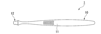
- FIG. 1 is a front view of the toothbrush 1 according to the present embodiment.
- FIG. 2 is a side view of the toothbrush 1.
- the toothbrush 1 includes a rod-shaped handle body 10 and a brush molded body 20.
- the handle body 10 and the brush molded body 20 are separate members.
- the brush molded body 20 can be detachably attached (inserted) to the handle body 10.
- the front surface in the present embodiment is the side on which the filament 23, which will be described later, protrudes from the normal direction (hereinafter, simply referred to as the normal direction) of the upper surface 21a (details will be described later) of the brush molded body 20.
- the length direction of the handle portion 11 and the direction in which the handle body 10 is inserted into the brush molded body 20 (hereinafter, simply referred to as the insertion direction) is orthogonal to the normal direction.
- the direction orthogonal to the normal direction and the insertion direction is the width direction of the brush molded body 20 (hereinafter, simply referred to as the width direction).
- FIG. 3 is a front view of the handle body 10.
- the handle body 10 includes a rod-shaped handle portion 11 and an insertion portion 12 provided at the tip of the handle portion 11 and projecting toward the tip end side of the handle portion 11 in the length direction. ..
- the insertion portion 12 of the handle body 10 is inserted into the brush molding body 20 described later, so that the insertion portion 12 is covered with the brush molding body 20 and attached.
- the front view shape of the handle portion 11 of the present embodiment is such that the width gradually narrows from the front end side to the rear end side and then extends at a constant width, and then gradually widens and then narrows. It changes in a curve.
- the front end of the handle portion 11 has a substantially semicircular shape at the rear end.
- the side view shape of the handle portion 11 extends from the front end side to the rear end side with a certain width, and then gradually widens to the maximum thickness of the finger rest portion.
- the side view shape of the handle portion 11 changes in a curve so that the width gradually narrows from the finger contact portion having the maximum thickness toward the rear end side.
- the side view shape of the handle portion 11 has a substantially semicircular shape at the rear end portion.
- the shape of the handle portion is not limited to the shape of this example, and can be appropriately set in consideration of strength, operability, design, and the like.
- the dimensions of the handle portion 11 are not particularly limited and can be set as appropriate.
- the length of the handle portion 11 can be 100 to 200 mm.
- the insertion portion 12 is a portion covered with the brush molded body 20 in a state where the brush molded body 20 is attached to the handle body 10.
- the rear end of the insertion portion 12 is the rear end position of the brush molded body 20 in a state where the brush molded body 20 is attached to the handle body 10.
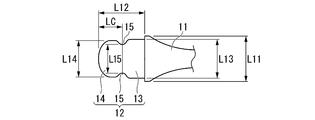
- FIG. 4 is an enlarged front view of the insertion portion 12.
- FIG. 5 is an enlarged side view of the insertion portion 12.
- the insertion portion 12 has a base portion 13 provided on the tip end side of the handle portion 11 and a tip portion 14 provided on the tip end of the base portion 13.
- the base portion 13 and the tip portion 14 have steps on both the front side and the back surface side with respect to the handle portion 11 and are formed to have the same thickness thinner than the handle portion 11.
- the base 13 has a substantially rectangular shape in a plan view.
- the base portion 13 has a step on both sides in the width direction with respect to the handle portion 11, and is formed with a width L13 narrower than the maximum width L11 on the tip end side of the handle portion 11 (L13 ⁇ L11).
- the tip portion 14 has a substantially elliptical shape in a plan view with the width direction as the major axis direction.
- the tip portion 14 has a substantially elliptical shape on both sides in the width direction, with side edges cut out in a straight line parallel to the insertion direction of the insertion portion 12.
- the tip portion 14 has a step on both sides in the width direction with respect to the base portion 13 and is formed with a width L14 narrower than the width L13 of the base portion 13.
- the insertion portion 12 is substantially in the center of the insertion direction, and has a recess 15 between the base portion 13 and the tip portion 14.
- the recesses 15 are provided on both sides in the width direction.
- the recess 15 has an arc shape having an arc center on the outside and a concave on the inside in the width direction.
- the shortest distance L15 between the recesses 15 is shorter than the width L13 of the base 13 and the width L14 of the tip 14.
- the amount of the recess 15 in the tip 14 with respect to the edge defining the width L14 is, for example, 1 mm.
- the position of the apex of the recess 15 recessed inward is within a range of 30% or more and 70% or less of the maximum length L12 of the insertion portion 12 in the insertion direction on the rear end side, starting from the tip of the insertion portion 12 in the insertion direction. It is preferably located, and more preferably located in the range of 40% or more and 60% or less. Further, the entire region forming the recess 15 is preferably located in the range of 30% or more and 70% or less of the maximum length L12, and more preferably located in the range of 40% or more and 60% or less (details are detailed. See below).
- the maximum depth of the recess 15 inward in the width direction is preferably 0.5 mm or more and 1.8 mm or less, preferably 0.8 mm or more and 1. It is more preferably 5 mm or less (details will be described later).
- the shape of the recess 15 it is possible to strengthen the fitting between the brush molded body 20 and the handle body 10.
- an arc shape is exemplified, but it may be a substantially rectangular shape, and a so-called burrs may be attached to the tip end side of the insertion portion of the dent 15.
- the maple has a shape in which the recessing direction of the recess 15 is not vertical toward the inside in the width direction but diagonally toward the handle portion 11.
- the recess 15 exemplifies a shape that is concave inward on both sides in the width direction of the insertion portion 12, it may be a shape that is convex outward.
- the handle body 10 is made of a hard resin.
- a resin having a flexural modulus (JIS K7171) of 1500 MPa or more and 3000 MPa or less can be exemplified.
- PP polypropylene resin
- POM polyacetal resin
- PCTA polyester resin
- PETG polyethylene terephthalate copolymer
- HDPE high-density polyethylene
- PP which is a general-purpose resin, is preferable in consideration of cost.
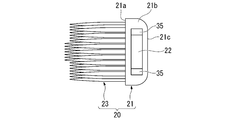
- FIG. 6 is a front view of the brush molded body 20.
- FIG. 7 is a cross-sectional view taken along the line AA in FIG.
- the brush molded body 20 includes a head base portion 21 having a substantially rectangular front view shape, and a plurality of filaments 23 provided on the front surface of the head base portion 21. There is.
- the filament 23 is a substantially columnar shape protruding from the upper surface 21a of the head base portion 21 to the front side.
- the filament 23 has a substantially triangular prism shape having a substantially triangular cross section on the base end side, and a triangular pyramid shape on the tip end side extending from the substantially triangular prism and tapering.
- the filament 23 As the tapered shape of the filament 23, a shape having one or more change points of the taper angle and having two change points of 0 to 2 mm and 4 to 8 mm from the tip can be exemplified. Further, the filament 23 may have a quadrangular pyramid shape. Even if the filament 23 has a quadrangular pyramid shape, it can be exemplified that the filament 23 has one or more change points of the taper angle and the change points are provided at two points of 0 to 2 mm and 4 to 8 mm from the tip. By adopting this configuration, it is possible to improve the cleanability while ensuring the moldability.
- the filament 23 is provided with a plurality of rows along the insertion direction so that the rows arranged along the width direction of the brush molded body 20 are offset by half a pitch from the adjacent rows in the insertion direction. That is, the filaments 23 are arranged in a staggered pattern.
- FIG. 8 is a view of the brush molded body 20 as viewed from the rear end side.
- the filament 23 has a high center in the width direction and a low outside in the width direction.
- the filament 23 may have a flat shape with no height difference in the width direction.
- the outer side in the direction may be higher, but when the dome shape has a higher center in the width direction, it is possible to further improve the cleanability in the oral cavity.
- the height difference of the filament is preferably 0.5 to 3.0 mm, more preferably 0.5 to 2.0 mm.
- the region where the central filament 23 is located (the width in the width direction of the filament base end (the maximum width of the region in the width direction where the filament base end is located)) is 20 to 45 of the length in the width direction occupied by the entire filament. It is preferably%, and more preferably 25 to 40%.
- the filament arrangement pitch is preferably 0.5 to 1.5 mm in both the length direction and the width direction, and more preferably 0.8 to 1.2 mm.
- the maximum length of the filament 23 is preferably 7 mm or more and 15 mm or less, and more preferably 9 mm or more and 13 mm or less. If the maximum length of the filament 23 is less than 7 mm, the cleanability in the oral cavity may be reduced. If the maximum length of the filament 23 exceeds 15 mm, the releasability when the brush molded body 20 is molded by injection molding is lowered. By setting the maximum length of the filament 23 to 7 mm or more and 15 mm or less, it is possible to secure the cleanability in the oral cavity and the releasability at the time of molding.
- the cross-sectional area of the base end of the filament 23 is preferably 0.8 mm 2 or less, more preferably 0.6 mm 2 or less, and further preferably 0.4 mm 2 or less.
- the cross-sectional area of the proximal end of the filament 23 exceeds 0.8 mm 2 , the filament 23 is less likely to bend, and there is a possibility that the cleanability of gaps between teeth and the cervical region may be reduced.
- the ratio of the total cross-sectional area of the base ends of the plurality of filaments 23 to the area of the upper surface 21a of the head base portion 21 is preferably 10% or more and 50% or less. If the ratio of the total cross-sectional area of the proximal end of the filament 23 is less than 10%, the cleanability in the oral cavity may be deteriorated. If the ratio of the total cross-sectional area of the base end of the filament 23 exceeds 50%, the releasability when the brush molded body 20 is molded by injection molding is lowered. By setting the ratio of the total cross-sectional area of the base end of the filament 23 to 10% or more and 50% or less, it is possible to secure the cleanability in the oral cavity and the releasability at the time of molding.
- a substantially polygonal shape such as a substantially quadrangle, a substantially circular shape, a substantially star shape, a substantially spatula shape, or the like can be selected.
- the filament 23 may have a tapered shape with a tapered tip, a straight extending structure, or a tapered shape with a tapered tip.
- the upper surface 21a of the head base portion 21 is a flat surface parallel to the width direction and the insertion direction.
- the upper surface 21a is flush with the position of the proximal end of the filament 23 with respect to the protruding direction of the filament 23.
- the upper surface 21a forms the outer contour (outermost circumference) of the head base portion 21. That is, the upper surface 21a is a parting surface for injection molding the brush molded body 20.
- the head base portion 21 has an insertion hole 22 that extends in the insertion direction and opens to the end surface 21b on the rear end side.
- FIG. 9 is a cross-sectional view of a plane parallel to the upper surface 21a including the insertion hole 22. As shown in FIG. 9, the insertion hole 22 has a first portion 33 that opens to the end surface 21b and a second portion 34 that is located behind the first portion 33. As shown in FIG. 7, the first portion 33 and the second portion 34 are formed to have the same thickness thinner than the head base portion 21.
- the head base portion 21 has a protrusion 35 located substantially in the center of the insertion hole 22 in the insertion direction and located between the first portion 33 and the second portion 34.
- the protrusions 35 are provided on both sides of the insertion hole 22 in the width direction.
- the protrusions 35 are provided at positions where the insertion portion 12 fits into the recess 15 when the insertion portion 12 is inserted into the insertion hole 22.
- the protrusion 35 has an arc shape having an arc center on the outside in the width direction and being convex inward.
- the maximum width L21 on the rear end side (end surface 21b) of the head base portion 21 is substantially the same as the maximum width L11 on the front end side of the handle portion 11.
- the front view shape of the insertion hole 22 is substantially the same as the front view shape of the insertion portion 12.
- the width L33 of the first portion 33 is a length into which the base portion 13 in the insertion portion 12 can be inserted, and is substantially the same as the maximum width L13 of the base portion 13.
- the width L34 of the second portion 34 is a length into which the tip portion 14 of the insertion portion 12 can be inserted, and is substantially the same as the maximum width L14 of the tip portion 14.
- the shortest distance L35 between the protrusions 35 is shorter than the width L33 of the first portion 33 and the width L34 of the second portion 34.
- the shortest distance L35 between the protrusions 35 is a length into which the tip portion 14 and the recess 15 in the insertion portion 12 can be inserted, and is substantially the same as the shortest distance L15 between the recesses 15.
- the amount of protrusion of the protrusion 35 inward in the width direction with respect to the second portion 34 is, for example, 1 mm.
- the amount of protrusion of the protrusion 35 with respect to the second portion 34 is the amount of undercut when the mold (slide core) for forming the insertion hole 22 is pulled out to the rear end side during injection molding of the brush molded body 20.
- the maximum distance (maximum thickness) T between the upper surface 21a of the head base portion 21 and the second surface 21c on the back surface side is preferably 2.0 mm or more and 4.5 mm or less.
- the maximum distance T is less than 2.0 mm, the gap between the upper surface 21a and the surface of the insertion hole 22 on the upper surface 21a side, or between the second surface 21c and the surface of the insertion hole 22 on the second surface 21c side. Since the gap between the two is reduced and the fluidity of the molten resin is reduced during molding, the resin may be unfilled.
- the maximum distance T exceeds 4.5 mm, the operability when the brush molded body 20 is inserted into the oral cavity may decrease.
- the distance (maximum length) in the width direction of the head base portion 21 is not particularly limited, but is, for example, 10 to 16 mm. In particular, when the maximum length of the head base portion 21 in the width direction is 13 to 16 mm, the operability in the oral cavity can be ensured by making the head portion thin even though the head is wide.
- the height t1 of the insertion hole 22 is preferably 1.0 mm or more and 2.5 mm or less.
- the thickness (distance) t2 of the head base portion 21 between the upper surface 21a and the surface of the insertion hole 22 on the upper surface 21a side is preferably 0.5 mm or more and 2.0 mm or less.
- the thickness (distance) t3 of the head base portion 21 between the second surface 21c on the back surface side of the head base portion 21 and the surface on the second surface 21c side of the insertion hole 22 is 0.5 mm or more. It is preferably 0 mm or less.
- the maximum length of the head base portion 21 in the insertion direction is L1 and the maximum length of the insertion hole 22 in the insertion direction is L2, the maximum length of the head base portion 21 represented by L2 / L1.
- the ratio of the maximum length L2 of the insertion hole 22 to L1 is preferably 0.30 or more and 0.70 or less, more preferably 0.40 or more and 0.60 or less, and 0.45 or more. It is more preferably 0.55 or less.
- the distance between the tip end of the insertion hole 22 and the tip end of the head base 21 represented by L1-L2 is preferably 5 mm or more and 15 mm or less, preferably 8 mm or more. It is more preferably 12 mm or less.
- the resin flow is restricted, so that the moldability of the filament 23 is lowered.
- the value represented by L1-L2 exceeds 15 mm, the region where the insertion portion 12 formed of the hard resin does not exist becomes large, so that the front surface of the brush molded body 20 tends to bend, and usability may decrease. There is sex.
- the minimum distance S between the base end of the filament 23 located on the most distal end side and the back surface of the head base portion 21 is preferably 1.5 mm or more and 3.0 mm or less.
- the minimum thickness of the head base portion 21 is preferably 1.0 to 2.5 mm. By setting the minimum thickness of the head base portion 21 to this range, it is possible to improve the operability in the oral cavity while reducing the discomfort when the tip of the head portion comes into contact with the oral tissue.
- the insertion hole 22 (that is, the insertion hole 22 is formed) on the tip side of the insertion hole 22 in the brush molded body 20.
- the resin can flow in the region where the slide core for molding the insertion hole 22 does not exist in the mold, so that the obstacle of the resin fluidity due to the presence of the slide core is suppressed and the filament 23 is molded. Sex improves.
- the gate position for filling the resin into the mold can be selected, for example, the tip of the head base portion 21, but is not particularly limited.
- the gate position can be arranged, for example, on the back surface or the rear end of the head base portion 21, and it is possible to avoid a problem that the uncut portion (gate mark) of the gate cut damages the oral tissue.
- a recess 35M (see FIG. 10) for forming the protrusion 35 to be fitted in the recess 15 is formed in the slide core in the normal direction. Will be.
- the recess 35M constitutes a resin flow flow path connecting the back side to the front side of the slide core in which the insertion hole 22 is molded in the mold at the time of molding. Normally, the resin flow is restricted in the region occupied by the slide core, but the moldability of the filament 23 is improved by securing the recess 35M for molding the protrusion 35 as the flow path of the resin flow.
- the recess 15 is 30% or more and 70% or less of the maximum length L12 of the insertion portion 12 in the insertion direction on the rear end side, starting from the tip in the insertion direction of the insertion portion 12.
- the recess 35M of the slide core for forming the protrusion 35 is located near the center of the insertion hole 22 in the insertion direction. If the position of the protrusion 35 is outside the above range in the insertion direction of the insertion portion 12, the resin flow during molding may be biased and the filament 23 may not be uniformly molded. By setting the position of the protrusion 35 within the above range in the insertion direction of the insertion portion 12, the bias of the resin flow is suppressed and the filament 23 can be uniformly molded.
- the maximum depth of the recess 15 (projection 35) inward in the width direction is preferably 0.5 mm or more and 1.8 mm or less (0.8 mm or more, 1.5 mm or less). Is more preferable).
- the maximum depth of the recess 15 inward in the width direction is less than 0.5 mm, the recess 35M is formed only on the edge of the slide core, so that a large improvement in resin fluidity cannot be expected and the fitting with the protrusion 35 cannot be expected. There is a possibility that the brush molded body 20 will fall off when the toothbrush 1 is used due to the weakening of the resin.
- the fitting (undercut amount) with the protrusion 35 becomes large, and the insertion portion 12 may break at the time of mold release.
- the maximum depth of the recess 15 inward in the width direction to 0.5 mm or more and 1.8 mm or less, it is possible to improve the resin fluidity, prevent the brush molded body 20 from falling off, and prevent the insertion portion 12 from breaking. it can.
- the handle body 10 has a brush on the tip end side of the insertion portion of the recess 15, the fitting between the brush molded body 20 and the handle body 10 can be further strengthened.
- the head base portion 21 has a thin-walled region 21d in which the tip end side of the back surface 21c gradually inclines toward the front end side and gradually becomes thinner toward the tip end side.
- the maximum length L3 of the thin-walled region 21d in the insertion direction is preferably 40% or more, preferably 50% or more of the maximum length L1 of the head base portion 21 in the insertion direction. More preferred.
- the maximum length L3 of the thin region 21d By setting the maximum length L3 of the thin region 21d to 40% or more of the maximum length L1 of the head base portion 21, the volume on the back surface side of the brush molded body 20 can be reduced, so that the molten resin is placed on the upper surface 21a side during molding. Can be preferentially flowed, and the moldability of the filament 23 can be improved. This effect becomes more remarkable when the gate position is arranged at the tip of the head base portion 21.
- the maximum length L3 of the thin region 21d is less than 40% of the maximum length L1 of the head base portion 21, the improvement in moldability may be diluted.
- polyurethane As the soft resin constituting the brush molded body 20, various elastomers can be used, but polyurethane is preferable. Polyurethane tends to have higher tensile strength than other elastomers such as styrene-based and polyester-based elastomers. Therefore, by using polyurethane as the soft resin, mechanical strength can be secured even if the thickness is thin, and the insertion portion 12 It is possible to suppress damage when the toothbrush is fitted with the insertion hole 22 and when the toothbrush 1 is used.
- polyurethane 0.01-1.0 wt% (mass%) of saturated / unsaturated hydrocarbons of C10 or more, higher alcohols, fatty acid amides, fatty acid ester low molecular weight polyethylene, polyethylene glycol (PEG), fatty acid metal salts, etc. It functions as a lubricant or a mold release agent when it is blended with any one of long-chain fatty acids, fatty acid glycerin, and silicone, or in combination.
- polyurethane has a wide range of hardness that can be selected as compared with the other elastomers described above, and the resin hardness can be selected in consideration of its usability (for example, bending of the tip of the brush molded body) according to the thickness of the brush molded body 20. It is possible.
- the hardness of the polyurethane is preferably shore 90A or more and 70D or less. If the hardness of the polyurethane is softer than that of the shore 90A, it is likely to be deformed when it is formed of a thin wall, so that the fitting is weakened and the brush molded body 20 is likely to fall off when the toothbrush 1 is used.
- the hardness of the polyurethane is harder than the shore 70D, pain may occur when the tip hits the oral tissue when the back surface of the head base 21 is tilted.
- shore 90A or more and 70D or less it is possible to prevent the brush molded body 20 from falling off when the toothbrush 1 is used, or to prevent pain when the tip of the head base portion 21 hits.
- polyurethane it is preferable to use an ether-based polyurethane from the viewpoint of ensuring water resistance and antibacterial properties.
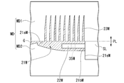
- FIG. 10 is a cross-sectional view briefly showing an example of a mold MD for molding the brush molded body 20.
- FIG. 11 is a cross-sectional view briefly showing the mold MD before mold clamping.
- the mold MD includes a first mold MD1 and a second mold MD2 that move relative to each other in the opening / closing direction (vertical direction in FIG. 10).
- the first mold MD1 and the second mold MD2 are molded with the parting surface PL flush with the upper surface 21a as a joint surface.
- the first mold MD1 is attached to, for example, the fixed side of an injection molding machine, and the molten resin is filled from the injection molding machine.
- the second mold MD2 is attached to, for example, the movable side of the injection molding machine, and by moving in the opening / closing direction with respect to the first mold MD1, the mold MD is also opened / closed.
- the first mold MD1 has a molding surface 21aM on which the upper surface 21a is molded and a cavity 23M on which the filament 23 is molded when the mold is compacted and joined to the second mold MD2.
- the second mold MD2 has a cavity 21M in which the head base portion 21 is formed when the mold is compacted and joined to the first mold MD1, and the cavity 21M is opened to the tip side, and molten resin is introduced into the cavity 21M. It has a gate portion G to be formed and a contact surface 21eM provided at a position of an end surface 21b in the insertion direction and orthogonal to the insertion direction.
- a gate portion G for example, a side gate method is used, but a pinpoint gate method or a tunnel gate method may be used.
- the contact surface 21eM extends in the direction away from the PL surface from the position where the back surface of the head base portion 21 is formed in the second mold MD2.
- the second mold MD is provided with a slide core SL.
- the slide core SL has a core portion 22M in which the insertion hole 22 is formed, and a molding surface 21bM in which the core portion 22M protrudes and is orthogonal to the insertion direction. As shown in FIG. 11, the molding surface 21bM is separated from the contact surface 21eM before mold clamping.
- the first mold MD1 and the second mold MD2 are molded, a part of the molding surface 21bM comes into contact with the contact surface 21eM as shown in FIG. 10, and the core portion 22M Is positioned at the position where it is inserted into the cavity 21M.
- the region facing the cavity 21M without contacting the contact surface 21eM is a region for molding the end surface 21b.
- the slide core SL has a core so that the core portion 22M does not interfere with the release of the molded brush molded body 20 when the first mold MD1 and the second mold MD2 are opened.
- the portion 22M moves in a direction away from the cavity 21M.
- the movement direction of the slide core SL is preferably horizontal in order to avoid unexpected movement due to its own weight.
- the configuration of the mold MD illustrates that the insertion hole 22 of the brush molded body 20 is formed by the slide core SL, but the handle body 10 is inserted into the mold MD and the brush molded body 20 is secondarily molded. You can also choose the method. In that case, it is disadvantageous to make the brush molded body 20 and the handle body 10 detachable, but the post-step of fitting the handle body 10 and the brush molded body 20 after molding can be omitted.
- the dimensions of the R chamfering process and the C chamfering process are preferably 1.5 mm or more, and more preferably 3.0 mm or more.
- the molten resin introduced into the cavity 21M from the gate portion G in a state where the first mold MD1 and the second mold MD2 are molded is on the tip side of the core portion 22M in the cavity 21M. Due to the fact that a sufficient volume is secured and the back surface side of the cavity 21M is inclined and thinned, the molten resin introduced into the tip side of the cavity 21M flows preferentially to the upper surface 21a side.
- the cavity 23M can be filled with the molten resin with sufficient filling pressure.
- the molten resin introduced into the back side of the core portion 22M can flow to the front side using the recess 35M formed near the center of the core portion 22M in the insertion direction as a flow path. It is possible to uniformly mold the filament 23 in a state where the bias of the resin flow is suppressed in the direction.
- the resin flows even when the thickness of the head base portion 21 is reduced to 2.0 mm or more and 4.5 mm or less by using the brush molded body 20 having a fitting structure. It is possible to provide a toothbrush 1 having excellent intraoral operability by molding the brush molded body 20 without deteriorating the properties.
- the maximum distance T between the base end of the filament and the back surface of the head base portion is 2.0 mm or more and 4.5 mm or less, and the maximum length L1 of the head base portion is 1.
- L2 / L1 which is the ratio of the maximum length L2 of the insertion hole to the above is 0.30 or more and 0.70 or less, the moldability of the filament, the difficulty of bending the brush molded body, and the like. Good results were obtained in all of the ease of polishing the entire oral cavity.
- Comparative Example 1 in which L2 / L1, which is the ratio of the maximum length L2 of the insertion hole to the maximum length L1 of the head base portion, is less than 0.30, the brush molded body is bent. Good results were not obtained regarding the texture. Further, in Comparative Example 2 in which L2 / L1, which is the ratio of the maximum length L2 of the insertion hole to the maximum length L1 of the head base portion exceeds 0.70, good results regarding the moldability of the filament were obtained. There wasn't.
- the center position LC of the recess with the tip of the insertion portion as the base point is less than 3 mm, which is the ratio of the position LC of the recess to the maximum length L12 (maximum length L2 of the insertion hole) of the insertion portion 12 in the insertion direction.
- the ratio of / L12 (LC / L2) is less than 30%
- the center position LC of the recess with the tip of the insertion portion as the base point exceeds 7 mm, and the maximum length L12 (insertion) of the insertion portion 12 in the insertion direction.
- Example 7 in which the ratio of LC / L12 (LC / L2), which is the ratio of the position LC of the recess to the maximum hole length L2), is 70% or more, the moldability of the filament is as good as that of Example 1. No results were obtained.
- Comparative Example 1 in which the difference between the maximum length L1 of the head base portion and the maximum length L2 of the insertion hole, which is represented by L1-L2, exceeds 15 mm, regarding the difficulty of bending the brush molded body. In addition to the fact that good results were not obtained, the results were not as good as in Example 1 regarding the ease of polishing the entire oral cavity.
- the upper surface 21a forming the outer contour (outermost circumference) of the head base portion 21 and the base end of the filament 23 are flush with each other, and the filament 23 projects from the upper surface 21a.
- the upper surface 21a is provided with a base portion that is located inside the outer contour of the head base portion 21 and protrudes from the upper surface 21a with a certain thickness, and the filament 23 protrudes from the upper surface of the base portion instead of the upper surface 21a (.
- the upper surface of the base portion and the base end of the filament 23 are flush with each other).
- the brush molded body 20 becomes thicker by the thickness of the base portion, it is preferable that the upper surface 21a serving as the parting surface PL and the base end of the filament 23 are flush with each other.
- the fluidity of the resin is lower than that when the base portion is provided, so that the action of the present invention becomes more remarkable.
- the configuration in which the handle body 10 is formed of a hard resin is illustrated, but the present invention is not limited to this configuration, and for example, a part of the handle body 10 (handle portion 10, etc.) is coated with a soft resin. It may have a different configuration. When this configuration is adopted, the decorativeness and grip can be improved.
- the present invention can be applied to a toothbrush.
Abstract
The present invention provides a toothbrush that provides excellent handleability within the oral cavity even when a brush molding having a fitting structure is in use. This toothbrush is equipped with: a handle body which is formed of a hard resin; and a brush molding (20) which is formed of a soft resin and provided to the leading end side of the handle body. The handle body has an insertion part provided so as to protrude on the leading end side thereof. The brush molding includes a head base body (21) and filaments (23) that protrude from the front face side of the head base body. The head base body has formed therein an insertion hole (22) in which the insertion part is inserted and fitted. The brush molding is configured such that: the maximum distance between the base end of the filaments and the back-side surface (21c) of the head base body is 2.0-4.5 mm; and, when the maximum length of the head base body in the insertion direction is defined as L1, and when the maximum length of the insertion hole in the insertion direction is defined as L2, the proportion, represented by L2/L1, of the maximum length of the insertion hole to the maximum length of the head base body is 0.30-0.70.
Description
本発明は、歯ブラシに関する。
本願は、2019年12月23日に、日本に出願された特願2019-231982号に基づき優先権を主張し、その内容をここに援用する。 The present invention relates to a toothbrush.
The present application claims priority based on Japanese Patent Application No. 2019-231982 filed in Japan on December 23, 2019, the contents of which are incorporated herein by reference.
射出成形機のみで歯ブラシを製造する一体成形歯ブラシが提案されている(例えば、特許文献1)。一体成形歯ブラシは、フィラメントとヘッド基台部(あるいはヘッド部)を一体的に成形するため、フィラメントの材料調達および植毛機が不要であり、植毛歯ブラシよりも安価に製造できる利点を有している。
An integrally molded toothbrush that manufactures a toothbrush only with an injection molding machine has been proposed (for example, Patent Document 1). Since the integrally molded toothbrush integrally molds the filament and the head base (or head), there is no need to procure filament materials and a flocking machine, and the integrally molded toothbrush has an advantage that it can be manufactured at a lower cost than a flocking toothbrush. ..
刷掃用の一体成形歯ブラシとしては、フィラメントおよび挿入孔を有するヘッド部(ブラシ成形体)と、挿入部を一端に設けたハンドル部とを別々に成形し、それらを嵌合させることで一体成形歯ブラシを提供することが提案されている(例えば、特許文献2、3)。特許文献2、3に記載された歯ブラシでは、ヘッド部が使用者により交換可能となるため、ヘッド部のみを廃棄してハンドルは繰り返し使用できるといった省資源化が期待される。
As an integrally molded toothbrush for sweeping, a head portion (brush molded body) having a filament and an insertion hole and a handle portion provided with an insertion portion at one end are separately molded and integrally molded by fitting them. It has been proposed to provide a toothbrush (eg, Patent Documents 2 and 3). In the toothbrushes described in Patent Documents 2 and 3, since the head portion can be replaced by the user, resource saving is expected such that only the head portion can be discarded and the handle can be used repeatedly.
口腔内操作性、特に奥歯に対する操作性の観点から歯ブラシのヘッド部には薄型化が望まれている。
ところが、上述したような従来の歯ブラシでは、挿入孔を形成する必要があり、必然的にヘッド部の厚さに対して樹脂の占める割合が小さくなる。そのため、ブラシ成形体を薄型化すると樹脂で形成される厚さがさらに薄くなり、結果として成形時の樹脂流動性が低下する。成形時の樹脂流動性が低下した場合、フィラメントの成形性が低下するという問題が生じる。そこで、ハンドル部の挿入部を薄くすることも考えられるが、この場合、挿入部の樹脂強度および挿入部を成形するための金型の強度を確保できないという問題が生じる。 From the viewpoint of operability in the oral cavity, particularly operability for the back teeth, the head portion of the toothbrush is desired to be thin.
However, in the conventional toothbrush as described above, it is necessary to form an insertion hole, and the ratio of the resin to the thickness of the head portion is inevitably small. Therefore, when the brush molded body is made thinner, the thickness formed by the resin is further reduced, and as a result, the resin fluidity at the time of molding is lowered. When the resin fluidity at the time of molding is lowered, there arises a problem that the moldability of the filament is lowered. Therefore, it is conceivable to make the insertion portion of the handle portion thinner, but in this case, there arises a problem that the resin strength of the insertion portion and the strength of the mold for molding the insertion portion cannot be secured.
本発明は、以上のような点を考慮してなされたもので、嵌合構造のブラシ成形体を用いた場合でも口腔内操作性に優れた歯ブラシを提供することを目的とする。
The present invention has been made in consideration of the above points, and an object of the present invention is to provide a toothbrush having excellent oral operability even when a brush molded body having a fitting structure is used.
本発明の第1の態様に従えば、硬質樹脂で形成されたハンドル体と、軟質樹脂で形成され前記ハンドル体の先端側に設けられたブラシ成形体とを備え、前記ハンドル体は、先端側に突出して設けられた挿入部を有し、前記ブラシ成形体は、ヘッド基台部と、前記ヘッド基台の正面側に突出するフィラメントとを有し、前記ヘッド基台部は、前記挿入部が差し込まれて嵌合する挿入孔を有し、前記ブラシ成形体は、前記フィラメントの基端とヘッド基台部の背面との最大距離が2.0mm以上、4.5mm以下であり、差し込み方向の前記ヘッド基台部の最大長さをL1とし、前記差し込み方向の前記挿入孔の最大長さをL2とすると、L2/L1で表される、前記ヘッド基台部の最大長さに対する前記挿入孔の最大長さの割合は、0.30以上、0.70以下であることを特徴とする歯ブラシが提供される。
According to the first aspect of the present invention, the handle body is provided with a handle body made of a hard resin and a brush molded body made of a soft resin and provided on the tip end side of the handle body, and the handle body is on the tip end side. The brush molded body has a head base portion and a filament protruding toward the front side of the head base, and the head base portion is the insertion portion. The brush molded body has an insertion hole into which the filament is inserted and fits, and the maximum distance between the base end of the filament and the back surface of the head base portion is 2.0 mm or more and 4.5 mm or less, and the insertion direction. If the maximum length of the head base portion is L1 and the maximum length of the insertion hole in the insertion direction is L2, the insertion with respect to the maximum length of the head base portion represented by L2 / L1. Toothbrushes are provided in which the ratio of the maximum length of the holes is 0.30 or more and 0.70 or less.
また、上記本発明の一態様に係る歯ブラシにおいて、L1-L2で表される、前記挿入孔の前記先端側の端部と前記ヘッド基台部の前記先端側の端部との距離は、5mm以上、15mm以下であることを特徴とする。
Further, in the toothbrush according to one aspect of the present invention, the distance between the tip end side of the insertion hole and the tip end side of the head base portion represented by L1-L2 is 5 mm. As mentioned above, it is characterized in that it is 15 mm or less.
また、上記本発明の一態様に係る歯ブラシにおいて、前記ヘッド基台部は、前記背面の前記先端側が前記先端側に向かうに従って漸次前記正面側に向かって傾斜して漸次薄くなる薄肉領域を有し、前記薄肉領域の前記差し込み方向の最大長さは、前記ヘッド基台部の前記差し込み方向の最大長さの40%以上であることを特徴とする。
Further, in the toothbrush according to one aspect of the present invention, the head base portion has a thin-walled region that gradually inclines toward the front side as the tip side of the back surface toward the tip side and gradually becomes thinner. The maximum length of the thin-walled region in the insertion direction is 40% or more of the maximum length of the head base portion in the insertion direction.
また、上記本発明の一態様に係る歯ブラシにおいて、前記挿入部は、前記フィラメントの突出方向と直交する方向の端縁に、内側に凹となる一つ以上の窪みを有し、前記ヘッド基台部は、前記挿入孔に前記挿入部が差し込まれたときに、前記窪みと嵌合する位置に突起を有することを特徴とする。
Further, in the toothbrush according to one aspect of the present invention, the insertion portion has one or more recesses inwardly recessed at the edge in the direction orthogonal to the protruding direction of the filament, and the head base. The portion is characterized by having a protrusion at a position where it fits with the recess when the insertion portion is inserted into the insertion hole.
また、上記本発明の一態様に係る歯ブラシにおいて、前記窪みは、前記フィラメントの突出方向および前記差し込み方向と直交する幅方向の端縁に設けられ、且つ、前記挿入部の前記差し込み方向の先端を起点として、後端側に前記挿入部の前記差し込み方向の最大長さ30%以上、70%以下の範囲に位置することを特徴とする。
Further, in the toothbrush according to one aspect of the present invention, the recess is provided at the edge in the width direction orthogonal to the protrusion direction and the insertion direction of the filament, and the tip of the insertion portion in the insertion direction is provided. As a starting point, the insertion portion is located on the rear end side within a range of 30% or more and 70% or less of the maximum length of the insertion portion in the insertion direction.
また、上記本発明の一態様に係る歯ブラシにおいて、前記軟質樹脂は、ポリウレタンであることを特徴とする。
Further, in the toothbrush according to one aspect of the present invention, the soft resin is polyurethane.
また、上記本発明の一態様に係る歯ブラシにおいて、前記フィラメントの突出方向に関して、前記フィラメントの基端の位置は、前記ブラシ成形体のパーティング面の位置と同一であることを特徴とする。
Further, in the toothbrush according to one aspect of the present invention, the position of the base end of the filament is the same as the position of the parting surface of the brush molded body with respect to the protruding direction of the filament.
本発明では、嵌合構造のブラシ成形体を用いた場合でも口腔内操作性に優れた歯ブラシを提供できる。
According to the present invention, it is possible to provide a toothbrush having excellent oral operability even when a brush molded body having a fitting structure is used.
以下、本発明の歯ブラシの実施形態を、図1ないし図11を参照して説明する。
なお、以下の実施形態は、本発明の一態様を示すものであり、この発明を限定するものではなく、本発明の技術的思想の範囲内で任意に変更可能である。また、以下の図面においては、各構成をわかりやすくするために、実際の構造と各構造における縮尺や数等を異ならせている。 Hereinafter, embodiments of the toothbrush of the present invention will be described with reference to FIGS. 1 to 11.
It should be noted that the following embodiments show one aspect of the present invention, do not limit the present invention, and can be arbitrarily changed within the scope of the technical idea of the present invention. Further, in the following drawings, in order to make each configuration easy to understand, the scale and number of each structure are different from the actual structure.
図1は、本実施形態に係る歯ブラシ1の正面図である。図2は、歯ブラシ1の側面図である。歯ブラシ1は、棒状のハンドル体10と、ブラシ成形体20とを備えている。ハンドル体10とブラシ成形体20とは別々の部材である。ブラシ成形体20は、ハンドル体10に着脱自在に装着(差し込み)可能である。
FIG. 1 is a front view of the toothbrush 1 according to the present embodiment. FIG. 2 is a side view of the toothbrush 1. The toothbrush 1 includes a rod-shaped handle body 10 and a brush molded body 20. The handle body 10 and the brush molded body 20 are separate members. The brush molded body 20 can be detachably attached (inserted) to the handle body 10.
なお、本実施形態における正面とは、ブラシ成形体20の上面21a(詳細は後述)の法線方向(以下では、単に法線方向と称する)のうち後述するフィラメント23が突出する側である。また、ハンドル部11の長さ方向であり、ブラシ成形体20に対してハンドル体10が差し込まれる方向(以下、単に差し込み方向と称する)は、上記法線方向と直交する。上記法線方向と差し込み方向と直交する方向は、ブラシ成形体20の幅方向(以下、単に幅方向と称する)である。
The front surface in the present embodiment is the side on which the filament 23, which will be described later, protrudes from the normal direction (hereinafter, simply referred to as the normal direction) of the upper surface 21a (details will be described later) of the brush molded body 20. Further, the length direction of the handle portion 11 and the direction in which the handle body 10 is inserted into the brush molded body 20 (hereinafter, simply referred to as the insertion direction) is orthogonal to the normal direction. The direction orthogonal to the normal direction and the insertion direction is the width direction of the brush molded body 20 (hereinafter, simply referred to as the width direction).
図3は、ハンドル体10の正面図である。
ハンドル体10は、図3に示すように、棒状のハンドル部11と、ハンドル部の11の先端に設けられた、ハンドル部11の長さ方向先端側に突出する挿入部12とを備えている。歯ブラシ1では、ハンドル体10の挿入部12を後述のブラシ成形体20内に差し込むことで、挿入部12にブラシ成形体20を被せて取り付けるようになっている。 FIG. 3 is a front view of thehandle body 10.
As shown in FIG. 3, thehandle body 10 includes a rod-shaped handle portion 11 and an insertion portion 12 provided at the tip of the handle portion 11 and projecting toward the tip end side of the handle portion 11 in the length direction. .. In the toothbrush 1, the insertion portion 12 of the handle body 10 is inserted into the brush molding body 20 described later, so that the insertion portion 12 is covered with the brush molding body 20 and attached.
ハンドル体10は、図3に示すように、棒状のハンドル部11と、ハンドル部の11の先端に設けられた、ハンドル部11の長さ方向先端側に突出する挿入部12とを備えている。歯ブラシ1では、ハンドル体10の挿入部12を後述のブラシ成形体20内に差し込むことで、挿入部12にブラシ成形体20を被せて取り付けるようになっている。 FIG. 3 is a front view of the
As shown in FIG. 3, the
本実施形態のハンドル部11の正面視形状は、先端側から後端側に向かって徐々に幅が狭くなった後に一定の幅で延び、その後に徐々に幅が広くなった後に狭くなるように曲線的に変化する。ハンドル部11の正面視形状は、後端部が略半円形状になっている。
The front view shape of the handle portion 11 of the present embodiment is such that the width gradually narrows from the front end side to the rear end side and then extends at a constant width, and then gradually widens and then narrows. It changes in a curve. The front end of the handle portion 11 has a substantially semicircular shape at the rear end.
ハンドル部11の側面視形状は、図2に示すように、先端側から後端側に向かって一定の幅で延びた後に、指当て部となる最大厚さまで徐々に幅が広くなる。ハンドル部11の側面視形状は、最大厚さの指当て部から後端側に向かって徐々に幅が狭くなるように曲線的に変化する。ハンドル部11の側面視形状は、後端部が略半円形状になっている。
As shown in FIG. 2, the side view shape of the handle portion 11 extends from the front end side to the rear end side with a certain width, and then gradually widens to the maximum thickness of the finger rest portion. The side view shape of the handle portion 11 changes in a curve so that the width gradually narrows from the finger contact portion having the maximum thickness toward the rear end side. The side view shape of the handle portion 11 has a substantially semicircular shape at the rear end portion.
なお、本発明において、ハンドル部の形状は、この例の形状には限定されず、強度、操作性、意匠性等を考慮して適宜設定できる。
ハンドル部11の寸法は、特に限定されず、適宜設定できる。例えば、ハンドル部11の長さは、100~200mmとすることができる。 In the present invention, the shape of the handle portion is not limited to the shape of this example, and can be appropriately set in consideration of strength, operability, design, and the like.
The dimensions of thehandle portion 11 are not particularly limited and can be set as appropriate. For example, the length of the handle portion 11 can be 100 to 200 mm.
ハンドル部11の寸法は、特に限定されず、適宜設定できる。例えば、ハンドル部11の長さは、100~200mmとすることができる。 In the present invention, the shape of the handle portion is not limited to the shape of this example, and can be appropriately set in consideration of strength, operability, design, and the like.
The dimensions of the
挿入部12は、ハンドル体10にブラシ成形体20を取り付けた状態においてブラシ成形体20で被覆される部分である。挿入部12の後端は、ハンドル体10にブラシ成形体20が取り付けられた状態における、ブラシ成形体20の後端位置である。
The insertion portion 12 is a portion covered with the brush molded body 20 in a state where the brush molded body 20 is attached to the handle body 10. The rear end of the insertion portion 12 is the rear end position of the brush molded body 20 in a state where the brush molded body 20 is attached to the handle body 10.
図4は、挿入部12を拡大した正面図である。図5は、挿入部12を拡大した側面図である。
図4に示すように、挿入部12は、ハンドル部11の先端側に設けられた基部13と、基部13の先端に設けられた先端部14とを有している。図5に示すように、基部13と先端部14とは、正面側および背面側の両側でハンドル部11に対して段差を有しハンドル部11よりも薄い同一厚さで形成されている。 FIG. 4 is an enlarged front view of theinsertion portion 12. FIG. 5 is an enlarged side view of the insertion portion 12.
As shown in FIG. 4, theinsertion portion 12 has a base portion 13 provided on the tip end side of the handle portion 11 and a tip portion 14 provided on the tip end of the base portion 13. As shown in FIG. 5, the base portion 13 and the tip portion 14 have steps on both the front side and the back surface side with respect to the handle portion 11 and are formed to have the same thickness thinner than the handle portion 11.
図4に示すように、挿入部12は、ハンドル部11の先端側に設けられた基部13と、基部13の先端に設けられた先端部14とを有している。図5に示すように、基部13と先端部14とは、正面側および背面側の両側でハンドル部11に対して段差を有しハンドル部11よりも薄い同一厚さで形成されている。 FIG. 4 is an enlarged front view of the
As shown in FIG. 4, the
基部13は、平面視略矩形状である。基部13は、幅方向両側でハンドル部11に対して段差を有しハンドル部11の先端側の最大幅L11よりも狭い幅L13で形成されている(L13<L11)。先端部14は、幅方向を長径方向とする平面視略楕円形状である。先端部14は、略楕円形状の幅方向両側で、挿入部12の差し込み方向と平行な直線で側縁を切り欠いた形状である。先端部14は、幅方向両側で基部13に対して段差を有し基部13の幅L13よりも狭い幅L14で形成されている。
The base 13 has a substantially rectangular shape in a plan view. The base portion 13 has a step on both sides in the width direction with respect to the handle portion 11, and is formed with a width L13 narrower than the maximum width L11 on the tip end side of the handle portion 11 (L13 <L11). The tip portion 14 has a substantially elliptical shape in a plan view with the width direction as the major axis direction. The tip portion 14 has a substantially elliptical shape on both sides in the width direction, with side edges cut out in a straight line parallel to the insertion direction of the insertion portion 12. The tip portion 14 has a step on both sides in the width direction with respect to the base portion 13 and is formed with a width L14 narrower than the width L13 of the base portion 13.
挿入部12は、差し込み方向の略中央であって、基部13と先端部14との間に窪み15を有している。窪み15は、幅方向の両側に設けられている。窪み15は、幅方向で外側に円弧中心を有し内側に凹となる円弧形状である。窪み15同士の最短距離L15は、基部13の幅L13および先端部14の幅L14よりも短い。先端部14において幅L14を規定する端縁に対する窪み15の窪み量としては、一例として、1mmである。
The insertion portion 12 is substantially in the center of the insertion direction, and has a recess 15 between the base portion 13 and the tip portion 14. The recesses 15 are provided on both sides in the width direction. The recess 15 has an arc shape having an arc center on the outside and a concave on the inside in the width direction. The shortest distance L15 between the recesses 15 is shorter than the width L13 of the base 13 and the width L14 of the tip 14. The amount of the recess 15 in the tip 14 with respect to the edge defining the width L14 is, for example, 1 mm.
内側に窪んだ窪み15の頂点の位置は、挿入部12の差し込み方向の先端を起点として、後端側に挿入部12の差し込み方向の最大長さL12の30%以上、70%以下の範囲に位置することが好ましく、40%以上、60%以下の範囲に位置することがより好ましい。さらに、窪み15を形成する領域全体が最大長さL12の30%以上、70%以下の範囲に位置することが好ましく、40%以上、60%以下の範囲に位置することがより好ましい(詳細は後述)。窪み15の幅方向内側への最大深さ(基部13において幅L13を規定する端縁に対する窪み量)は、0.5mm以上、1.8mm以下であることが好ましく、0.8mm以上、1.5mm以下であることがより好ましい(詳細は後述)。
The position of the apex of the recess 15 recessed inward is within a range of 30% or more and 70% or less of the maximum length L12 of the insertion portion 12 in the insertion direction on the rear end side, starting from the tip of the insertion portion 12 in the insertion direction. It is preferably located, and more preferably located in the range of 40% or more and 60% or less. Further, the entire region forming the recess 15 is preferably located in the range of 30% or more and 70% or less of the maximum length L12, and more preferably located in the range of 40% or more and 60% or less (details are detailed. See below). The maximum depth of the recess 15 inward in the width direction (the amount of the recess with respect to the edge defining the width L13 at the base 13) is preferably 0.5 mm or more and 1.8 mm or less, preferably 0.8 mm or more and 1. It is more preferably 5 mm or less (details will be described later).
上記窪み15は形状を工夫することで、ブラシ成形体20とハンドル体10との嵌合を強固にすることが可能である。窪み15の形状として、円弧形状を例示したが、略矩形であってもよく、窪み15の挿入部先端側に、所謂、カエシが付いていてもよい。カエシとは、窪み15の窪み方向が幅方向内側に向かって垂直ではなく、ハンドル部11側に向かって斜めに窪む形状である。
また、上記窪み15は、挿入部12の幅方向両側に、内側に凹となる形状を例示したが、外側に凸となる形状であってもよい。 By devising the shape of therecess 15, it is possible to strengthen the fitting between the brush molded body 20 and the handle body 10. As the shape of the dent 15, an arc shape is exemplified, but it may be a substantially rectangular shape, and a so-called burrs may be attached to the tip end side of the insertion portion of the dent 15. The maple has a shape in which the recessing direction of the recess 15 is not vertical toward the inside in the width direction but diagonally toward the handle portion 11.
Further, although therecess 15 exemplifies a shape that is concave inward on both sides in the width direction of the insertion portion 12, it may be a shape that is convex outward.
また、上記窪み15は、挿入部12の幅方向両側に、内側に凹となる形状を例示したが、外側に凸となる形状であってもよい。 By devising the shape of the
Further, although the
ハンドル体10は、硬質樹脂で形成されている。
硬質樹脂としては、一例として、曲げ弾性率(JIS K7171)が1500MPa以上、3000MPa以下である樹脂を例示できる。具体的には、例えば、ポリプロピレン樹脂(PP)、ポリアセタール樹脂(POM)、ポリエステル樹脂(PCTA)、ポリエチレンテレフタレート共重合体(PETG)、高密度ポリエチレン(HDPE)を例示できる。これらの中でも、コスト面を考慮すると汎用樹脂であるPPが好ましい。 Thehandle body 10 is made of a hard resin.
As an example of the hard resin, a resin having a flexural modulus (JIS K7171) of 1500 MPa or more and 3000 MPa or less can be exemplified. Specifically, for example, polypropylene resin (PP), polyacetal resin (POM), polyester resin (PCTA), polyethylene terephthalate copolymer (PETG), and high-density polyethylene (HDPE) can be exemplified. Among these, PP, which is a general-purpose resin, is preferable in consideration of cost.
硬質樹脂としては、一例として、曲げ弾性率(JIS K7171)が1500MPa以上、3000MPa以下である樹脂を例示できる。具体的には、例えば、ポリプロピレン樹脂(PP)、ポリアセタール樹脂(POM)、ポリエステル樹脂(PCTA)、ポリエチレンテレフタレート共重合体(PETG)、高密度ポリエチレン(HDPE)を例示できる。これらの中でも、コスト面を考慮すると汎用樹脂であるPPが好ましい。 The
As an example of the hard resin, a resin having a flexural modulus (JIS K7171) of 1500 MPa or more and 3000 MPa or less can be exemplified. Specifically, for example, polypropylene resin (PP), polyacetal resin (POM), polyester resin (PCTA), polyethylene terephthalate copolymer (PETG), and high-density polyethylene (HDPE) can be exemplified. Among these, PP, which is a general-purpose resin, is preferable in consideration of cost.
図6は、ブラシ成形体20の正面図である。図7は、図6におけるA-A断面図である。図6および図7に示すように、ブラシ成形体20は、正面視形状が略矩形状のヘッド基台部21と、ヘッド基台部21の正面に設けられた複数のフィラメント23とを備えている。
FIG. 6 is a front view of the brush molded body 20. FIG. 7 is a cross-sectional view taken along the line AA in FIG. As shown in FIGS. 6 and 7, the brush molded body 20 includes a head base portion 21 having a substantially rectangular front view shape, and a plurality of filaments 23 provided on the front surface of the head base portion 21. There is.
フィラメント23は、ヘッド基台部21の上面21aから正面側に突出する略柱状である。フィラメント23は、基端側が断面略三角形状の略三角柱状であり、先端側が略三角柱から延びて先細る三角錐状である。
The filament 23 is a substantially columnar shape protruding from the upper surface 21a of the head base portion 21 to the front side. The filament 23 has a substantially triangular prism shape having a substantially triangular cross section on the base end side, and a triangular pyramid shape on the tip end side extending from the substantially triangular prism and tapering.
フィラメント23の先細り形状としては、テーパー角の変化点を1つ以上有し、先端から0~2mm、4~8mmの2ヶ所に変化点を設けた形状を例示できる。
また、フィラメント23は四角錐状であってもよい。フィラメント23が四角錐状であっても、テーパー角の変化点を1つ以上有し、先端から0~2mm、4~8mmの2ヶ所に変化点を設けた形状を例示できる。この構成を採ることにより、成形性を確保しながら、清掃性を高めることが可能となる。 As the tapered shape of thefilament 23, a shape having one or more change points of the taper angle and having two change points of 0 to 2 mm and 4 to 8 mm from the tip can be exemplified.
Further, thefilament 23 may have a quadrangular pyramid shape. Even if the filament 23 has a quadrangular pyramid shape, it can be exemplified that the filament 23 has one or more change points of the taper angle and the change points are provided at two points of 0 to 2 mm and 4 to 8 mm from the tip. By adopting this configuration, it is possible to improve the cleanability while ensuring the moldability.
また、フィラメント23は四角錐状であってもよい。フィラメント23が四角錐状であっても、テーパー角の変化点を1つ以上有し、先端から0~2mm、4~8mmの2ヶ所に変化点を設けた形状を例示できる。この構成を採ることにより、成形性を確保しながら、清掃性を高めることが可能となる。 As the tapered shape of the
Further, the
フィラメント23は、ブラシ成形体20の幅方向に沿って並ぶ列が、差し込み方向で隣り合う列同士が半ピッチずれるように、差し込み方向に沿って複数列設けられている。すなわち、フィラメント23は、千鳥状に配置されている。
The filament 23 is provided with a plurality of rows along the insertion direction so that the rows arranged along the width direction of the brush molded body 20 are offset by half a pitch from the adjacent rows in the insertion direction. That is, the filaments 23 are arranged in a staggered pattern.
図8は、ブラシ成形体20を後端側から視た図である。
図8に示すように、フィラメント23は、幅方向中央が高く、幅方向外側が低
フィラメント23は、幅方向で高低差のないフラット形状でもよく、高低が逆転して幅方向中央が低く、幅方向外側が高くてもよいが、幅方向中央が高いドーム形状とした場合に口腔内の清掃性をより高めることが可能となる。フィラメントの高低差としては0.5~3.0mmであることが好ましく、0.5~2.0mmであることがさらに好ましい。
中央のフィラメント23の位置する領域(フィラメント基端の幅方向の差し渡し幅(フィラメント基端が位置する幅方向の領域の最大幅))としては、フィラメント全体が占める幅方向の長さの20~45%であることが好ましく、25~40%であることがさらに好ましい。
また、フィラメントの配列ピッチについては長さ方向、幅方向ともに0.5~1.5mmであることが好ましく、0.8~1.2mmであることがさらに好ましい。 FIG. 8 is a view of the brush moldedbody 20 as viewed from the rear end side.
As shown in FIG. 8, thefilament 23 has a high center in the width direction and a low outside in the width direction. The filament 23 may have a flat shape with no height difference in the width direction. The outer side in the direction may be higher, but when the dome shape has a higher center in the width direction, it is possible to further improve the cleanability in the oral cavity. The height difference of the filament is preferably 0.5 to 3.0 mm, more preferably 0.5 to 2.0 mm.
The region where thecentral filament 23 is located (the width in the width direction of the filament base end (the maximum width of the region in the width direction where the filament base end is located)) is 20 to 45 of the length in the width direction occupied by the entire filament. It is preferably%, and more preferably 25 to 40%.
The filament arrangement pitch is preferably 0.5 to 1.5 mm in both the length direction and the width direction, and more preferably 0.8 to 1.2 mm.
図8に示すように、フィラメント23は、幅方向中央が高く、幅方向外側が低
フィラメント23は、幅方向で高低差のないフラット形状でもよく、高低が逆転して幅方向中央が低く、幅方向外側が高くてもよいが、幅方向中央が高いドーム形状とした場合に口腔内の清掃性をより高めることが可能となる。フィラメントの高低差としては0.5~3.0mmであることが好ましく、0.5~2.0mmであることがさらに好ましい。
中央のフィラメント23の位置する領域(フィラメント基端の幅方向の差し渡し幅(フィラメント基端が位置する幅方向の領域の最大幅))としては、フィラメント全体が占める幅方向の長さの20~45%であることが好ましく、25~40%であることがさらに好ましい。
また、フィラメントの配列ピッチについては長さ方向、幅方向ともに0.5~1.5mmであることが好ましく、0.8~1.2mmであることがさらに好ましい。 FIG. 8 is a view of the brush molded
As shown in FIG. 8, the
The region where the
The filament arrangement pitch is preferably 0.5 to 1.5 mm in both the length direction and the width direction, and more preferably 0.8 to 1.2 mm.
フィラメント23の最大長さとしては、7mm以上、15mm以下であることが好ましく、9mm以上、13mm以下であることがより好ましい。フィラメント23の最大長さが7mm未満の場合、口腔内の清掃性が低下する可能性がある。フィラメント23の最大長さが15mmを超えた場合、ブラシ成形体20を射出成形により成形する際の離型性が低下してしまう。フィラメント23の最大長さを7mm以上、15mm以下とすることにより、口腔内の清掃性および成形時の離型性を確保することができる。
The maximum length of the filament 23 is preferably 7 mm or more and 15 mm or less, and more preferably 9 mm or more and 13 mm or less. If the maximum length of the filament 23 is less than 7 mm, the cleanability in the oral cavity may be reduced. If the maximum length of the filament 23 exceeds 15 mm, the releasability when the brush molded body 20 is molded by injection molding is lowered. By setting the maximum length of the filament 23 to 7 mm or more and 15 mm or less, it is possible to secure the cleanability in the oral cavity and the releasability at the time of molding.
フィラメント23の基端の断面積としては、0.8mm2以下であることが好ましく、0.6mm2以下であることがより好ましく、0.4mm2以下であることがさらに好ましい。
フィラメント23の基端の断面積が0.8mm2を超えた場合、フィラメント23が撓みにくくなり、歯間や歯頸部等の隙間清掃性が低下する可能性がある。フィラメント23の基端の断面積を0.8mm2以下とすることにより、歯間や歯頸部等の隙間清掃性を確保することができる。 The cross-sectional area of the base end of thefilament 23 is preferably 0.8 mm 2 or less, more preferably 0.6 mm 2 or less, and further preferably 0.4 mm 2 or less.
When the cross-sectional area of the proximal end of the filament 23 exceeds 0.8 mm 2 , thefilament 23 is less likely to bend, and there is a possibility that the cleanability of gaps between teeth and the cervical region may be reduced. By setting the cross-sectional area of the base end of the filament 23 to 0.8 mm 2 or less, it is possible to ensure the cleanability of gaps between teeth and the cervical region.
フィラメント23の基端の断面積が0.8mm2を超えた場合、フィラメント23が撓みにくくなり、歯間や歯頸部等の隙間清掃性が低下する可能性がある。フィラメント23の基端の断面積を0.8mm2以下とすることにより、歯間や歯頸部等の隙間清掃性を確保することができる。 The cross-sectional area of the base end of the
When the cross-sectional area of the proximal end of the filament 23 exceeds 0.8 mm 2 , the
ヘッド基台部21の上面21aの面積に対する複数のフィラメント23の基端の総断面積の割合としては、10%以上、50%以下であることが好ましい。フィラメント23の基端の総断面積の割合が10%未満の場合、口腔内の清掃性が低下する可能性がある。フィラメント23の基端の総断面積の割合が50%を超えた場合、ブラシ成形体20を射出成形により成形する際の離型性が低下してしまう。フィラメント23の基端の総断面積の割合10%以上、50%以下とすることにより、口腔内の清掃性および成形時の離型性を確保することができる。
The ratio of the total cross-sectional area of the base ends of the plurality of filaments 23 to the area of the upper surface 21a of the head base portion 21 is preferably 10% or more and 50% or less. If the ratio of the total cross-sectional area of the proximal end of the filament 23 is less than 10%, the cleanability in the oral cavity may be deteriorated. If the ratio of the total cross-sectional area of the base end of the filament 23 exceeds 50%, the releasability when the brush molded body 20 is molded by injection molding is lowered. By setting the ratio of the total cross-sectional area of the base end of the filament 23 to 10% or more and 50% or less, it is possible to secure the cleanability in the oral cavity and the releasability at the time of molding.
フィラメント23の断面形状としては、略三角形の他に、略四角形などの略多角形や、略円形、略星形、略ヘラ形などを選択可能である。フィラメント23は、先端が先細るテーパー形状の他に、ストレート状に延びる構成や、基端から先細りするテーパー形状であってもよい。
As the cross-sectional shape of the filament 23, in addition to a substantially triangular shape, a substantially polygonal shape such as a substantially quadrangle, a substantially circular shape, a substantially star shape, a substantially spatula shape, or the like can be selected. The filament 23 may have a tapered shape with a tapered tip, a straight extending structure, or a tapered shape with a tapered tip.
ヘッド基台部21の上面21aは、幅方向および差し込み方向と平行な平面である。上面21aは、フィラメント23の突出方向に関して、フィラメント23の基端の位置と面一である。図6および図8に示すように、上面21aは、ヘッド基台部21における外形輪郭(最外周)を形成している。すなわち、上面21aは、ブラシ成形体20を射出成形する際のパーティング面である。
The upper surface 21a of the head base portion 21 is a flat surface parallel to the width direction and the insertion direction. The upper surface 21a is flush with the position of the proximal end of the filament 23 with respect to the protruding direction of the filament 23. As shown in FIGS. 6 and 8, the upper surface 21a forms the outer contour (outermost circumference) of the head base portion 21. That is, the upper surface 21a is a parting surface for injection molding the brush molded body 20.
ヘッド基台部21は、差し込み方向に延びて後端側の端面21bに開口する挿入孔22を有している。図9は、挿入孔22を含む上面21aと平行な面における断面図である。図9に示すように、挿入孔22は、端面21bに開口する第1部分33と、第1部分33よりも奥側に位置する第2部分34とを有している。図7に示すように、第1部分33と第2部分34とは、ヘッド基台部21よりも薄い同一厚さで形成されている。
The head base portion 21 has an insertion hole 22 that extends in the insertion direction and opens to the end surface 21b on the rear end side. FIG. 9 is a cross-sectional view of a plane parallel to the upper surface 21a including the insertion hole 22. As shown in FIG. 9, the insertion hole 22 has a first portion 33 that opens to the end surface 21b and a second portion 34 that is located behind the first portion 33. As shown in FIG. 7, the first portion 33 and the second portion 34 are formed to have the same thickness thinner than the head base portion 21.
ヘッド基台部21は、挿入孔22における差し込み方向の略中央であって、第1部分33と第2部分34との間に位置する突起35を有している。突起35は、挿入孔22の幅方向の両側に設けられている。突起35は、挿入孔22に挿入部12が差し込まれたときに、窪み15と嵌合する位置にそれぞれ設けられている。突起35は、幅方向で外側に円弧中心を有し内側に凸となる円弧形状である。
The head base portion 21 has a protrusion 35 located substantially in the center of the insertion hole 22 in the insertion direction and located between the first portion 33 and the second portion 34. The protrusions 35 are provided on both sides of the insertion hole 22 in the width direction. The protrusions 35 are provided at positions where the insertion portion 12 fits into the recess 15 when the insertion portion 12 is inserted into the insertion hole 22. The protrusion 35 has an arc shape having an arc center on the outside in the width direction and being convex inward.
ヘッド基台部21の後端側(端面21b)の最大幅L21は、ハンドル部11の先端側の最大幅L11と略同一である。
挿入孔22の正面視形状は、挿入部12の正面視形状と略同一である。第1部分33の幅L33は、挿入部12における基部13が差し込み可能な長さであり、基部13の最大幅L13と略同一である。第2部分34の幅L34は、挿入部12における先端部14が差し込み可能な長さであり、先端部14の最大幅L14と略同一である。 The maximum width L21 on the rear end side (end surface 21b) of the head base portion 21 is substantially the same as the maximum width L11 on the front end side of the handle portion 11.
The front view shape of theinsertion hole 22 is substantially the same as the front view shape of the insertion portion 12. The width L33 of the first portion 33 is a length into which the base portion 13 in the insertion portion 12 can be inserted, and is substantially the same as the maximum width L13 of the base portion 13. The width L34 of the second portion 34 is a length into which the tip portion 14 of the insertion portion 12 can be inserted, and is substantially the same as the maximum width L14 of the tip portion 14.
挿入孔22の正面視形状は、挿入部12の正面視形状と略同一である。第1部分33の幅L33は、挿入部12における基部13が差し込み可能な長さであり、基部13の最大幅L13と略同一である。第2部分34の幅L34は、挿入部12における先端部14が差し込み可能な長さであり、先端部14の最大幅L14と略同一である。 The maximum width L21 on the rear end side (
The front view shape of the
突起35同士の最短距離L35は、第1部分33の幅L33および第2部分34の幅L34よりも短い。突起35同士の最短距離L35は、挿入部12における先端部14および窪み15が差し込み可能な長さであり、窪み15同士の最短距離L15と略同一である。突起35の第2部分34に対する幅方向内側への突出量としては、一例として1mmである。突起35の第2部分34に対する突出量は、ブラシ成形体20の射出成形時に挿入孔22を成形する金型(スライドコア)を後端側に引き抜く際のアンダーカット量である。
なお、ハンドル体10が窪み15の挿入部先端側にカエシを有している場合には、ブラシ成形体20とハンドル体10との嵌合を一層強固にすることが可能になる。 The shortest distance L35 between theprotrusions 35 is shorter than the width L33 of the first portion 33 and the width L34 of the second portion 34. The shortest distance L35 between the protrusions 35 is a length into which the tip portion 14 and the recess 15 in the insertion portion 12 can be inserted, and is substantially the same as the shortest distance L15 between the recesses 15. The amount of protrusion of the protrusion 35 inward in the width direction with respect to the second portion 34 is, for example, 1 mm. The amount of protrusion of the protrusion 35 with respect to the second portion 34 is the amount of undercut when the mold (slide core) for forming the insertion hole 22 is pulled out to the rear end side during injection molding of the brush molded body 20.
When thehandle body 10 has a brush on the tip end side of the insertion portion of the recess 15, the fitting between the brush molded body 20 and the handle body 10 can be further strengthened.
なお、ハンドル体10が窪み15の挿入部先端側にカエシを有している場合には、ブラシ成形体20とハンドル体10との嵌合を一層強固にすることが可能になる。 The shortest distance L35 between the
When the
図7に戻り、ヘッド基台部21の上面21aと背面側の第2面21cとの最大距離(最大厚さ)Tは、2.0mm以上、4.5mm以下であることが好ましい。最大距離Tが2.0mm未満の場合、上面21aと挿入孔22の上面21a側の面との間の隙間、または、第2面21cと挿入孔22の第2面21c側の面との間の隙間が小さくなり、成形時に溶融樹脂の流動性が低下するため、樹脂が未充填になる可能性がある。最大距離Tが4.5mmを超えた場合、ブラシ成形体20を口腔内に挿入した際の操作性が低下する可能性がある。最大距離Tを2.0mm以上、4.5mm以下とすることにより、樹脂の充填性およびブラシ成形体20を口腔内に挿入した際の操作性を確保することができる。
Returning to FIG. 7, the maximum distance (maximum thickness) T between the upper surface 21a of the head base portion 21 and the second surface 21c on the back surface side is preferably 2.0 mm or more and 4.5 mm or less. When the maximum distance T is less than 2.0 mm, the gap between the upper surface 21a and the surface of the insertion hole 22 on the upper surface 21a side, or between the second surface 21c and the surface of the insertion hole 22 on the second surface 21c side. Since the gap between the two is reduced and the fluidity of the molten resin is reduced during molding, the resin may be unfilled. If the maximum distance T exceeds 4.5 mm, the operability when the brush molded body 20 is inserted into the oral cavity may decrease. By setting the maximum distance T to 2.0 mm or more and 4.5 mm or less, the resin filling property and the operability when the brush molded body 20 is inserted into the oral cavity can be ensured.
ヘッド基台部21の幅方向の距離(最大長さ)としては特に限定されないが、例えば10~16mmである。特に、ヘッド基台部21の幅方向の最大長さが13~16mmである場合、幅広のワイドヘッドでありながら、ヘッド部を薄くすることで口腔内操作性を確保できる。
The distance (maximum length) in the width direction of the head base portion 21 is not particularly limited, but is, for example, 10 to 16 mm. In particular, when the maximum length of the head base portion 21 in the width direction is 13 to 16 mm, the operability in the oral cavity can be ensured by making the head portion thin even though the head is wide.
挿入孔22の高さt1は、1.0mm以上、2.5mm以下であることが好ましい。上面21aと挿入孔22の上面21a側の面との間のヘッド基台部21の厚さ(距離)t2は、0.5mm以上、2.0mm以下であることが好ましい。ヘッド基台部21の背面側の第2面21cと挿入孔22の第2面21c側の面との間のヘッド基台部21の厚さ(距離)t3は、0.5mm以上、2.0mm以下であることが好ましい。
The height t1 of the insertion hole 22 is preferably 1.0 mm or more and 2.5 mm or less. The thickness (distance) t2 of the head base portion 21 between the upper surface 21a and the surface of the insertion hole 22 on the upper surface 21a side is preferably 0.5 mm or more and 2.0 mm or less. The thickness (distance) t3 of the head base portion 21 between the second surface 21c on the back surface side of the head base portion 21 and the surface on the second surface 21c side of the insertion hole 22 is 0.5 mm or more. It is preferably 0 mm or less.
また、差し込み方向のヘッド基台部21の最大長さをL1とし、差し込み方向の挿入孔22の最大長さをL2とすると、L2/L1で表される、ヘッド基台部21の最大長さL1に対する挿入孔22の最大長さL2の割合は、0.30以上、0.70以下であることが好ましく、0.40以上、0.60以下であることがより好ましく、0.45以上、0.55以下であることがさらに好ましい。
Further, assuming that the maximum length of the head base portion 21 in the insertion direction is L1 and the maximum length of the insertion hole 22 in the insertion direction is L2, the maximum length of the head base portion 21 represented by L2 / L1. The ratio of the maximum length L2 of the insertion hole 22 to L1 is preferably 0.30 or more and 0.70 or less, more preferably 0.40 or more and 0.60 or less, and 0.45 or more. It is more preferably 0.55 or less.
L2/L1表される値が0.30未満の場合、硬質樹脂で形成された挿入部12の存在しない領域が大きくなるため、ブラシ成形体20の前方が屈曲しやすくなり、歯ブラシ1の使用性が低下する可能性がある。L2/L1が0.70を超えた場合、成形時に挿入孔22を形成する金型(スライドコア)が占有する体積が大きくなり、樹脂流動が制限されるため、フィラメント23の成形性が低下してしまう。L2/L1で表される値を0.30以上、0.70以下とすることにより、フィラメント23の成形性低下を抑制しつつ、歯ブラシ1の使用性低下を抑制することができる。
When the value represented by L2 / L1 is less than 0.30, the region where the insertion portion 12 formed of the hard resin does not exist becomes large, so that the front surface of the brush molded body 20 is easily bent, and the usability of the toothbrush 1 is increased. May decrease. When L2 / L1 exceeds 0.70, the volume occupied by the mold (slide core) forming the insertion hole 22 during molding becomes large, and the resin flow is restricted, so that the moldability of the filament 23 deteriorates. It ends up. By setting the values represented by L2 / L1 to 0.30 or more and 0.70 or less, it is possible to suppress a decrease in the moldability of the filament 23 and a decrease in the usability of the toothbrush 1.
また、L1-L2で表される、挿入孔22の先端側の端部とヘッド基台部21の先端側の端部との距離は、5mm以上、15mm以下であることが好ましく、8mm以上、12mm以下であることがより好ましい。L1-L2で表される値が5mm未満の場合、樹脂流動が制限されるため、フィラメント23の成形性が低下してしまう。L1-L2で表される値が15mm超えた場合、硬質樹脂で形成された挿入部12の存在しない領域が大きくなるため、ブラシ成形体20の前方が屈曲しやすくなり、使用性が低下する可能性がある。L1-L2で表される値を5mm以上、15mm以下とすることにより、フィラメント23の成形性低下を抑制しつつ、歯ブラシ1の使用性低下を抑制することができる。
The distance between the tip end of the insertion hole 22 and the tip end of the head base 21 represented by L1-L2 is preferably 5 mm or more and 15 mm or less, preferably 8 mm or more. It is more preferably 12 mm or less. When the value represented by L1-L2 is less than 5 mm, the resin flow is restricted, so that the moldability of the filament 23 is lowered. When the value represented by L1-L2 exceeds 15 mm, the region where the insertion portion 12 formed of the hard resin does not exist becomes large, so that the front surface of the brush molded body 20 tends to bend, and usability may decrease. There is sex. By setting the values represented by L1-L2 to 5 mm or more and 15 mm or less, it is possible to suppress a decrease in the moldability of the filament 23 and a decrease in the usability of the toothbrush 1.
ブラシ成形体20におけるヘッド基台部21の最大厚さTを薄くする場合、上記の高さt1、厚さt2、t3を小さくすることが考えられるが、厚さt2、t3を小さくする場合には、成形時の軟質樹脂の流動性を考慮する必要がある。特に、厚さt2を小さくすると、フィラメント23の成形性に大きな影響を与える。具体的には厚さt2を小さくすると、ブラシ成形体20を成形するための金型において、フィラメント23に向かう軟質樹脂の流路の差し込み方向と直交する断面積が小さくなり、ショート等の成形不良が発生しやすくなり、フィラメント23の成形性が低下する。そのため、最も先端側に位置するフィラメント23の基端とヘッド基台部21の背面との最小距離Sとしては、1.5mm以上、3.0mm以下であることが好ましい。
When reducing the maximum thickness T of the head base portion 21 in the brush molded body 20, it is conceivable to reduce the above heights t1, thickness t2, and t3, but when reducing the thicknesses t2 and t3, It is necessary to consider the fluidity of the soft resin during molding. In particular, if the thickness t2 is reduced, the moldability of the filament 23 is greatly affected. Specifically, when the thickness t2 is reduced, in the mold for molding the brush molded body 20, the cross-sectional area orthogonal to the insertion direction of the flow path of the soft resin toward the filament 23 becomes smaller, resulting in molding defects such as short circuits. Is likely to occur, and the moldability of the filament 23 is lowered. Therefore, the minimum distance S between the base end of the filament 23 located on the most distal end side and the back surface of the head base portion 21 is preferably 1.5 mm or more and 3.0 mm or less.
ヘッド基台部21の最小厚さとしては、1.0~2.5mmであることが好ましい。ヘッド基台部21の最小厚さをこの範囲にすることで、ヘッド部先端が口腔内組織に接触したときの違和感を軽減しながら、口腔内操作性を高めることができる。
The minimum thickness of the head base portion 21 is preferably 1.0 to 2.5 mm. By setting the minimum thickness of the head base portion 21 to this range, it is possible to improve the operability in the oral cavity while reducing the discomfort when the tip of the head portion comes into contact with the oral tissue.
そこで、本実施形態では、厚さt2が小さい場合でも、軟質樹脂の流動性を良好とするため、ブラシ成形体20における挿入孔22よりも先端側に挿入孔22(すなわち、挿入孔22を成形する金型(スライドコア))が存在しない一定の領域が設けられている。これにより、成形時、金型内では挿入孔22を成形するためのスライドコアが存在しない領域に樹脂が流動できるため、スライドコアの存在に起因する樹脂流動性の障害が抑制されフィラメント23の成形性が向上する。なお、樹脂を金型内に充填するためのゲート位置は、例えばヘッド基台部21の先端を選択できるが、特に限定はされない。
ゲート位置は、例えば、ヘッド基台部21の背面や後端に配置することも可能であり、ゲート切断の切れ残り(ゲート痕)が口腔内組織を損傷するといった不具合を回避できる。 Therefore, in the present embodiment, in order to improve the fluidity of the soft resin even when the thickness t2 is small, the insertion hole 22 (that is, theinsertion hole 22 is formed) on the tip side of the insertion hole 22 in the brush molded body 20. There is a certain area where there is no mold (slide core) to be used. As a result, during molding, the resin can flow in the region where the slide core for molding the insertion hole 22 does not exist in the mold, so that the obstacle of the resin fluidity due to the presence of the slide core is suppressed and the filament 23 is molded. Sex improves. The gate position for filling the resin into the mold can be selected, for example, the tip of the head base portion 21, but is not particularly limited.
The gate position can be arranged, for example, on the back surface or the rear end of thehead base portion 21, and it is possible to avoid a problem that the uncut portion (gate mark) of the gate cut damages the oral tissue.
ゲート位置は、例えば、ヘッド基台部21の背面や後端に配置することも可能であり、ゲート切断の切れ残り(ゲート痕)が口腔内組織を損傷するといった不具合を回避できる。 Therefore, in the present embodiment, in order to improve the fluidity of the soft resin even when the thickness t2 is small, the insertion hole 22 (that is, the
The gate position can be arranged, for example, on the back surface or the rear end of the
また、上述のように、挿入部12に窪み15が設けられることにより、スライドコアには窪み15に嵌合する突起35を成形するための凹部35M(図10参照)が法線方向に形成されることになる。この凹部35Mは、成形時の金型内では挿入孔22が成形されるスライドコアの背面側から正面側を繋ぐ樹脂流動の流路を構成する。通常、スライドコアが占める領域は樹脂流動が制限されるが、突起35を成形するための凹部35Mを樹脂流動の流路として確保することにより、フィラメント23の成形性が向上する。
Further, as described above, by providing the recess 15 in the insertion portion 12, a recess 35M (see FIG. 10) for forming the protrusion 35 to be fitted in the recess 15 is formed in the slide core in the normal direction. Will be. The recess 35M constitutes a resin flow flow path connecting the back side to the front side of the slide core in which the insertion hole 22 is molded in the mold at the time of molding. Normally, the resin flow is restricted in the region occupied by the slide core, but the moldability of the filament 23 is improved by securing the recess 35M for molding the protrusion 35 as the flow path of the resin flow.
また、上述のように、窪み15(突起35)が、挿入部12の差し込み方向の先端を起点として、後端側に挿入部12の差し込み方向の最大長さL12の30%以上、70%以下、好ましくは40%以上、60%以下の範囲に位置することにより、突起35を成形するためのスライドコアの凹部35Mが挿入孔22の差し込み方向の中央付近に位置することになる。突起35の位置が挿入部12の差し込み方向で上記の範囲外にある場合には、成形時の樹脂流動に偏りが生じフィラメント23を一様に成形できない可能性がある。突起35の位置を挿入部12の差し込み方向で上記の範囲内とすることにより、樹脂流動の偏りが抑制されフィラメント23を一様に成形することが可能となる。
Further, as described above, the recess 15 (projection 35) is 30% or more and 70% or less of the maximum length L12 of the insertion portion 12 in the insertion direction on the rear end side, starting from the tip in the insertion direction of the insertion portion 12. By preferably locating in the range of 40% or more and 60% or less, the recess 35M of the slide core for forming the protrusion 35 is located near the center of the insertion hole 22 in the insertion direction. If the position of the protrusion 35 is outside the above range in the insertion direction of the insertion portion 12, the resin flow during molding may be biased and the filament 23 may not be uniformly molded. By setting the position of the protrusion 35 within the above range in the insertion direction of the insertion portion 12, the bias of the resin flow is suppressed and the filament 23 can be uniformly molded.
また、窪み15(突起35)の幅方向内側への最大深さ(基部13に対する窪み量)は、0.5mm以上、1.8mm以下であることが好ましい(0.8mm以上、1.5mm以下であることがより好ましい)。窪み15の幅方向内側への最大深さが0.5mm未満の場合、凹部35Mがスライドコアの辺縁のみに形成されるため、樹脂流動性の大きな向上が期待できないとともに、突起35との嵌合が弱くなり歯ブラシ1の使用時にブラシ成形体20が脱落する可能性がある。窪み15の幅方向内側への最大深さが1.8mmを超えた場合、突起35との嵌合(アンダーカット量)が大きくなり、離型時に挿入部12が破断する可能性がある。窪み15の幅方向内側への最大深さを0.5mm以上、1.8mm以下とすることにより、樹脂流動性の向上、ブラシ成形体20の脱落抑制および挿入部12の破断抑制を図ることができる。
なお、ハンドル体10が窪み15の挿入部先端側にカエシを有している場合には、ブラシ成形体20とハンドル体10との嵌合を一層強固にすることが可能になる。 The maximum depth of the recess 15 (projection 35) inward in the width direction (the amount of the recess with respect to the base 13) is preferably 0.5 mm or more and 1.8 mm or less (0.8 mm or more, 1.5 mm or less). Is more preferable). When the maximum depth of therecess 15 inward in the width direction is less than 0.5 mm, the recess 35M is formed only on the edge of the slide core, so that a large improvement in resin fluidity cannot be expected and the fitting with the protrusion 35 cannot be expected. There is a possibility that the brush molded body 20 will fall off when the toothbrush 1 is used due to the weakening of the resin. If the maximum depth of the recess 15 inward in the width direction exceeds 1.8 mm, the fitting (undercut amount) with the protrusion 35 becomes large, and the insertion portion 12 may break at the time of mold release. By setting the maximum depth of the recess 15 inward in the width direction to 0.5 mm or more and 1.8 mm or less, it is possible to improve the resin fluidity, prevent the brush molded body 20 from falling off, and prevent the insertion portion 12 from breaking. it can.
When thehandle body 10 has a brush on the tip end side of the insertion portion of the recess 15, the fitting between the brush molded body 20 and the handle body 10 can be further strengthened.
なお、ハンドル体10が窪み15の挿入部先端側にカエシを有している場合には、ブラシ成形体20とハンドル体10との嵌合を一層強固にすることが可能になる。 The maximum depth of the recess 15 (projection 35) inward in the width direction (the amount of the recess with respect to the base 13) is preferably 0.5 mm or more and 1.8 mm or less (0.8 mm or more, 1.5 mm or less). Is more preferable). When the maximum depth of the
When the
ヘッド基台部21は、背面21cの先端側が、先端側に向かうに従って漸次正面側に向かって傾斜して漸次薄くなる薄肉領域21dを有する。図7に示すように、薄肉領域21dの差し込み方向の最大長さL3は、ヘッド基台部21の差し込み方向の最大長さL1の40%以上であることが好ましく、50%以上であることがより好ましい。
The head base portion 21 has a thin-walled region 21d in which the tip end side of the back surface 21c gradually inclines toward the front end side and gradually becomes thinner toward the tip end side. As shown in FIG. 7, the maximum length L3 of the thin-walled region 21d in the insertion direction is preferably 40% or more, preferably 50% or more of the maximum length L1 of the head base portion 21 in the insertion direction. More preferred.
薄肉領域21dの最大長さL3をヘッド基台部21の最大長さL1の40%以上とすることにより、ブラシ成形体20の背面側の体積を減少できるため、成形時に溶融樹脂を上面21a側に優先的に流動させることができ、フィラメント23の成形性を向上させることができる。この効果は、ゲート位置がヘッド基台部21の先端に配置される場合により顕著となる。薄肉領域21dの最大長さL3がヘッド基台部21の最大長さL1の40%未満の場合には、上記成形性の向上は希薄となる可能性がある。なお、挿入部12と挿入孔22との嵌合時および歯ブラシ1の使用時に、軟質樹脂の破損を防ぐ点を考慮すると、ヘッド基台部21の背面21cから挿入部12の背面までの距離t3は0.5mm以上確保する必要がある。
By setting the maximum length L3 of the thin region 21d to 40% or more of the maximum length L1 of the head base portion 21, the volume on the back surface side of the brush molded body 20 can be reduced, so that the molten resin is placed on the upper surface 21a side during molding. Can be preferentially flowed, and the moldability of the filament 23 can be improved. This effect becomes more remarkable when the gate position is arranged at the tip of the head base portion 21. When the maximum length L3 of the thin region 21d is less than 40% of the maximum length L1 of the head base portion 21, the improvement in moldability may be diluted. In consideration of preventing damage to the soft resin when the insertion portion 12 and the insertion hole 22 are fitted and when the toothbrush 1 is used, the distance t3 from the back surface 21c of the head base portion 21 to the back surface of the insertion portion 12. It is necessary to secure 0.5 mm or more.
ブラシ成形体20を構成する軟質樹脂としては、各種エラストマーを用いることができるが、ポリウレタンであることが好ましい。
ポリウレタンは、スチレン系やポリステル系などの他のエラストマーに比べて、引張強度が高い傾向にあるため、軟質樹脂にポリウレタンを用いることで、薄肉にしても機械的な強度が確保でき、挿入部12と挿入孔22との嵌合時および歯ブラシ1の使用時の破損を抑制することができる。 As the soft resin constituting the brush moldedbody 20, various elastomers can be used, but polyurethane is preferable.
Polyurethane tends to have higher tensile strength than other elastomers such as styrene-based and polyester-based elastomers. Therefore, by using polyurethane as the soft resin, mechanical strength can be secured even if the thickness is thin, and theinsertion portion 12 It is possible to suppress damage when the toothbrush is fitted with the insertion hole 22 and when the toothbrush 1 is used.
ポリウレタンは、スチレン系やポリステル系などの他のエラストマーに比べて、引張強度が高い傾向にあるため、軟質樹脂にポリウレタンを用いることで、薄肉にしても機械的な強度が確保でき、挿入部12と挿入孔22との嵌合時および歯ブラシ1の使用時の破損を抑制することができる。 As the soft resin constituting the brush molded
Polyurethane tends to have higher tensile strength than other elastomers such as styrene-based and polyester-based elastomers. Therefore, by using polyurethane as the soft resin, mechanical strength can be secured even if the thickness is thin, and the
ポリウレタン中には、0.01~1.0wt%(質量%)のC10以上の飽和/不飽和炭化水素、高級アルコール、脂肪酸アミド、脂肪酸エステル低分子量ポリエチレン、ポリエチレングリコール(PEG)、脂肪酸金属塩、長鎖脂肪酸、脂肪酸グリセリン、シリコーンのいずれか、あるいは複合して配合され、滑剤、離型剤として機能する。
In polyurethane, 0.01-1.0 wt% (mass%) of saturated / unsaturated hydrocarbons of C10 or more, higher alcohols, fatty acid amides, fatty acid ester low molecular weight polyethylene, polyethylene glycol (PEG), fatty acid metal salts, etc. It functions as a lubricant or a mold release agent when it is blended with any one of long-chain fatty acids, fatty acid glycerin, and silicone, or in combination.
また、ポリウレタンは上記の他のエラストマーに比べて選択できる硬度が幅広く、ブラシ成形体20の厚さに応じて、その使用性(例えば、ブラシ成形体先端の屈曲)を考慮した樹脂硬度の選択が可能である。ポリウレタンの硬度としては、ショア90A以上、70D以下であることが好ましい。
ポリウレタンの硬度がショア90Aよりも軟らかい場合、薄肉で形成されたときに変形しやすくなることから、嵌合が弱くなって歯ブラシ1の使用時にブラシ成形体20が脱落しやすくなってしまう。ポリウレタンの硬度がショア70Dよりも硬い場合、ヘッド基台部21の背面が傾斜した場合に先端が口腔組織に当たった時に痛みが生じる可能性がある。ポリウレタンの硬度をショア90A以上、70D以下とすることにより、歯ブラシ1の使用時にブラシ成形体20が脱落したり、ヘッド基台部21の先端が当たった時に痛みが生じることを抑制できる。 Further, polyurethane has a wide range of hardness that can be selected as compared with the other elastomers described above, and the resin hardness can be selected in consideration of its usability (for example, bending of the tip of the brush molded body) according to the thickness of the brush moldedbody 20. It is possible. The hardness of the polyurethane is preferably shore 90A or more and 70D or less.
If the hardness of the polyurethane is softer than that of the shore 90A, it is likely to be deformed when it is formed of a thin wall, so that the fitting is weakened and the brush moldedbody 20 is likely to fall off when the toothbrush 1 is used. If the hardness of the polyurethane is harder than the shore 70D, pain may occur when the tip hits the oral tissue when the back surface of the head base 21 is tilted. By setting the hardness of the polyurethane to shore 90A or more and 70D or less, it is possible to prevent the brush molded body 20 from falling off when the toothbrush 1 is used, or to prevent pain when the tip of the head base portion 21 hits.
ポリウレタンの硬度がショア90Aよりも軟らかい場合、薄肉で形成されたときに変形しやすくなることから、嵌合が弱くなって歯ブラシ1の使用時にブラシ成形体20が脱落しやすくなってしまう。ポリウレタンの硬度がショア70Dよりも硬い場合、ヘッド基台部21の背面が傾斜した場合に先端が口腔組織に当たった時に痛みが生じる可能性がある。ポリウレタンの硬度をショア90A以上、70D以下とすることにより、歯ブラシ1の使用時にブラシ成形体20が脱落したり、ヘッド基台部21の先端が当たった時に痛みが生じることを抑制できる。 Further, polyurethane has a wide range of hardness that can be selected as compared with the other elastomers described above, and the resin hardness can be selected in consideration of its usability (for example, bending of the tip of the brush molded body) according to the thickness of the brush molded
If the hardness of the polyurethane is softer than that of the shore 90A, it is likely to be deformed when it is formed of a thin wall, so that the fitting is weakened and the brush molded
また、ポリウレタンとしては、耐水性と抗菌性とを確保する観点から、エーテル系ポリウレタンを用いることが好ましい。
Further, as the polyurethane, it is preferable to use an ether-based polyurethane from the viewpoint of ensuring water resistance and antibacterial properties.
図10は、ブラシ成形体20を成形する金型MDの一例を簡略的に示した断面図である。図11は、型締前の金型MDを簡略的に示した断面図である。
金型MDは、開閉方向(図10中、上下方向)に相対移動する第1金型MD1と第2金型MD2とを備えている。第1金型MD1と第2金型MD2とは、上面21aと面一なパーティング面PLを接合面として型締される。 FIG. 10 is a cross-sectional view briefly showing an example of a mold MD for molding the brush moldedbody 20. FIG. 11 is a cross-sectional view briefly showing the mold MD before mold clamping.
The mold MD includes a first mold MD1 and a second mold MD2 that move relative to each other in the opening / closing direction (vertical direction in FIG. 10). The first mold MD1 and the second mold MD2 are molded with the parting surface PL flush with theupper surface 21a as a joint surface.
金型MDは、開閉方向(図10中、上下方向)に相対移動する第1金型MD1と第2金型MD2とを備えている。第1金型MD1と第2金型MD2とは、上面21aと面一なパーティング面PLを接合面として型締される。 FIG. 10 is a cross-sectional view briefly showing an example of a mold MD for molding the brush molded
The mold MD includes a first mold MD1 and a second mold MD2 that move relative to each other in the opening / closing direction (vertical direction in FIG. 10). The first mold MD1 and the second mold MD2 are molded with the parting surface PL flush with the
第1金型MD1は、射出成形機の例えば、固定側に取り付けられ、射出成形機から溶融樹脂が充填される。第2金型MD2は、射出成形機の例えば、可動側に取り付けられ、第1金型MD1に対して上記開閉方向に移動することにより、金型MDも開閉が行われる。
The first mold MD1 is attached to, for example, the fixed side of an injection molding machine, and the molten resin is filled from the injection molding machine. The second mold MD2 is attached to, for example, the movable side of the injection molding machine, and by moving in the opening / closing direction with respect to the first mold MD1, the mold MD is also opened / closed.
第1金型MD1は、型締されて第2金型MD2と接合したときに、上面21aが成形される成形面21aMと、フィラメント23が成形されるキャビティ23Mとを有している。
The first mold MD1 has a molding surface 21aM on which the upper surface 21a is molded and a cavity 23M on which the filament 23 is molded when the mold is compacted and joined to the second mold MD2.
第2金型MD2は、型締されて第1金型MD1と接合したときにヘッド基台部21が成形されるキャビティ21Mと、キャビティ21Mの先端側に開口し、キャビティ21Mに溶融樹脂が導入されるゲート部Gと、差し込み方向において端面21bの位置に設けられ、差し込み方向と直交する当接面21eMとを有している。ゲート部Gとしては、例えば、サイドゲート方式が用いられるが、ピンポイントゲート方式、トンネルゲート方式を用いてもよい。当接面21eMは、第2金型MD2において、ヘッド基台部21における背面を成形する位置からPL面と離れる方向に延びている。
The second mold MD2 has a cavity 21M in which the head base portion 21 is formed when the mold is compacted and joined to the first mold MD1, and the cavity 21M is opened to the tip side, and molten resin is introduced into the cavity 21M. It has a gate portion G to be formed and a contact surface 21eM provided at a position of an end surface 21b in the insertion direction and orthogonal to the insertion direction. As the gate portion G, for example, a side gate method is used, but a pinpoint gate method or a tunnel gate method may be used. The contact surface 21eM extends in the direction away from the PL surface from the position where the back surface of the head base portion 21 is formed in the second mold MD2.
第2金型MDには、スライドコアSLが設けられている。スライドコアSLは、挿入孔22が成形されるコア部22Mと、コア部22Mが突出し差し込み方向と直交する成形面21bMとを有している。図11に示すように、型締前において成形面21bMは、当接面21eMと離れている。スライドコアSLは、第1金型MD1と第2金型MD2とが型締されたときに、図10に示すように、成形面21bMの一部が当接面21eMと当接し、コア部22Mがキャビティ21Mに挿入される位置に位置決めされる。成形面21bMのうち、当接面21eMと当接せずにキャビティ21Mに臨む領域は、端面21bを成形する領域である。また、スライドコアSLは、第1金型MD1と第2金型MD2とが型開したときに、成形されたブラシ成形体20の離型にコア部22Mが支障を来さないように、コア部22Mがキャビティ21Mから離脱する方向に移動する。スライドコアSLの移動方向は、自重による不測の移動を回避するために水平方向であることが好ましい。
The second mold MD is provided with a slide core SL. The slide core SL has a core portion 22M in which the insertion hole 22 is formed, and a molding surface 21bM in which the core portion 22M protrudes and is orthogonal to the insertion direction. As shown in FIG. 11, the molding surface 21bM is separated from the contact surface 21eM before mold clamping. In the slide core SL, when the first mold MD1 and the second mold MD2 are molded, a part of the molding surface 21bM comes into contact with the contact surface 21eM as shown in FIG. 10, and the core portion 22M Is positioned at the position where it is inserted into the cavity 21M. Of the molding surface 21bM, the region facing the cavity 21M without contacting the contact surface 21eM is a region for molding the end surface 21b. Further, the slide core SL has a core so that the core portion 22M does not interfere with the release of the molded brush molded body 20 when the first mold MD1 and the second mold MD2 are opened. The portion 22M moves in a direction away from the cavity 21M. The movement direction of the slide core SL is preferably horizontal in order to avoid unexpected movement due to its own weight.
上記金型MDの構成は、スライドコアSLによりブラシ成形体20の挿入孔22を形成することを例示したが、金型MDにハンドル体10を挿入し、ブラシ成形体20を2次成形する製造方法も選択できる。その場合はブラシ成形体20とハンドル体10とを着脱自在とすることが不利となるが、成形後にハンドル体10とブラシ成形体20とを嵌合する後工程を省略できる。
The configuration of the mold MD illustrates that the insertion hole 22 of the brush molded body 20 is formed by the slide core SL, but the handle body 10 is inserted into the mold MD and the brush molded body 20 is secondarily molded. You can also choose the method. In that case, it is disadvantageous to make the brush molded body 20 and the handle body 10 detachable, but the post-step of fitting the handle body 10 and the brush molded body 20 after molding can be omitted.
スライドコアSLの先端側の背面はヘッド基台部21の傾斜背面と接近するため、R面取り加工やC面取り加工を施すことで、スライドコアSLの離脱時やハンドル体10の挿入部12との嵌合時に、ヘッド基台部21の破損(樹脂の破れ)を防ぐことが可能となる。R面取り加工やC面取り加工の寸法としては1.5mm以上であることが好ましく、3.0mm以上であることがさらに好ましい。
Since the back surface on the tip side of the slide core SL is close to the inclined back surface of the head base portion 21, by performing R chamfering processing or C chamfering processing, when the slide core SL is detached or with the insertion portion 12 of the handle body 10. At the time of fitting, it is possible to prevent the head base portion 21 from being damaged (the resin is torn). The dimensions of the R chamfering process and the C chamfering process are preferably 1.5 mm or more, and more preferably 3.0 mm or more.
上記の金型MDにおいて、第1金型MD1と第2金型MD2とが型締された状態でゲート部Gからキャビティ21Mに導入された溶融樹脂は、キャビティ21Mにおけるコア部22Mよりも先端側に充分な容積が確保されていること、およびキャビティ21Mの先端側において背面側が傾斜して薄くなっていることにより、キャビティ21Mの先端側に導入された溶融樹脂を上面21a側に優先的に流動させることができ、充分な充填圧により、キャビティ23Mに溶融樹脂を充填することができる。
In the above mold MD, the molten resin introduced into the cavity 21M from the gate portion G in a state where the first mold MD1 and the second mold MD2 are molded is on the tip side of the core portion 22M in the cavity 21M. Due to the fact that a sufficient volume is secured and the back surface side of the cavity 21M is inclined and thinned, the molten resin introduced into the tip side of the cavity 21M flows preferentially to the upper surface 21a side. The cavity 23M can be filled with the molten resin with sufficient filling pressure.
また、キャビティ21Mにおいて、コア部22Mの背面側に導入された溶融樹脂は、コア部22Mの差し込み方向の中央付近に形成された凹部35Mを流路として正面側に流動することができるため、差し込み方向で樹脂流動の偏りを抑制した状態でフィラメント23を一様に成形することが可能である。
Further, in the cavity 21M, the molten resin introduced into the back side of the core portion 22M can flow to the front side using the recess 35M formed near the center of the core portion 22M in the insertion direction as a flow path. It is possible to uniformly mold the filament 23 in a state where the bias of the resin flow is suppressed in the direction.
以上説明したように、本実施形態の歯ブラシ1では、嵌合構造のブラシ成形体20を用いヘッド基台部21の厚さを2.0mm以上、4.5mm以下に薄くした場合でも、樹脂流動性が低下することなくブラシ成形体20を成形して口腔内操作性に優れた歯ブラシ1を提供することが可能になる。
As described above, in the toothbrush 1 of the present embodiment, the resin flows even when the thickness of the head base portion 21 is reduced to 2.0 mm or more and 4.5 mm or less by using the brush molded body 20 having a fitting structure. It is possible to provide a toothbrush 1 having excellent intraoral operability by molding the brush molded body 20 without deteriorating the properties.
[実施例]
以下、実施例を示して本発明を詳細に説明するが、本発明は以下の実施例に限定されるものではなく、その要旨を逸脱しない範囲で適宜変更して実施することができる。 [Example]
Hereinafter, the present invention will be described in detail with reference to Examples, but the present invention is not limited to the following Examples, and can be appropriately modified and carried out without departing from the gist thereof.
(実施例1~7、比較例1~2)
[表1]に示す仕様に従って、上述したフィラメントの基端とヘッド基台部の背面との最大距離;T、フィラメントの基端とヘッド基台部の背面との最小距離;S、挿入孔の高さ;t1、ヘッド基台部の最大長さ;L1、挿入孔の最大長さ;L2、ヘッド基台部の最大長さL1に対する挿入孔の最大長さL2の割合;L2/L1、ヘッド基台部の最大長さL1と挿入孔の最大長さL2との差;L1-L2、薄肉領域の最大長さ;L3、最大長さL1に対する最大長さL3の割合;L3/L1、窪みの有無、挿入部先端を基点とした窪みの位置;LC、挿入部12の差し込み方向の最大長さL12(挿入孔の最大長さL2)に対する窪みの位置LCの割合;LC/L12(LC/L2)の少なくとも一つが異なる歯ブラシを実施例1~7、比較例1~2のサンプルとした。各サンプルを構成する樹脂は、ポリウレタンとした。 (Examples 1 to 7, Comparative Examples 1 to 2)
According to the specifications shown in [Table 1], the maximum distance between the base end of the filament and the back surface of the head base portion described above; T, the minimum distance between the base end of the filament and the back surface of the head base portion; S, of the insertion hole. Height; t1, maximum length of head base; L1, maximum length of insertion hole; L2, ratio of maximum length L2 of insertion hole to maximum length L1 of head base; L2 / L1, head Difference between the maximum length L1 of the base portion and the maximum length L2 of the insertion hole; L1-L2, the maximum length of the thin-walled region; L3, the ratio of the maximum length L3 to the maximum length L1; L3 / L1, dent Presence or absence, position of the dent based on the tip of the insertion part; LC, ratio of the position LC of the dent to the maximum length L12 (maximum length L2 of the insertion hole) of theinsertion part 12 in the insertion direction; LC / L12 (LC / Toothbrushes in which at least one of L2) is different were used as samples of Examples 1 to 7 and Comparative Examples 1 and 2. The resin constituting each sample was polyurethane.
[表1]に示す仕様に従って、上述したフィラメントの基端とヘッド基台部の背面との最大距離;T、フィラメントの基端とヘッド基台部の背面との最小距離;S、挿入孔の高さ;t1、ヘッド基台部の最大長さ;L1、挿入孔の最大長さ;L2、ヘッド基台部の最大長さL1に対する挿入孔の最大長さL2の割合;L2/L1、ヘッド基台部の最大長さL1と挿入孔の最大長さL2との差;L1-L2、薄肉領域の最大長さ;L3、最大長さL1に対する最大長さL3の割合;L3/L1、窪みの有無、挿入部先端を基点とした窪みの位置;LC、挿入部12の差し込み方向の最大長さL12(挿入孔の最大長さL2)に対する窪みの位置LCの割合;LC/L12(LC/L2)の少なくとも一つが異なる歯ブラシを実施例1~7、比較例1~2のサンプルとした。各サンプルを構成する樹脂は、ポリウレタンとした。 (Examples 1 to 7, Comparative Examples 1 to 2)
According to the specifications shown in [Table 1], the maximum distance between the base end of the filament and the back surface of the head base portion described above; T, the minimum distance between the base end of the filament and the back surface of the head base portion; S, of the insertion hole. Height; t1, maximum length of head base; L1, maximum length of insertion hole; L2, ratio of maximum length L2 of insertion hole to maximum length L1 of head base; L2 / L1, head Difference between the maximum length L1 of the base portion and the maximum length L2 of the insertion hole; L1-L2, the maximum length of the thin-walled region; L3, the ratio of the maximum length L3 to the maximum length L1; L3 / L1, dent Presence or absence, position of the dent based on the tip of the insertion part; LC, ratio of the position LC of the dent to the maximum length L12 (maximum length L2 of the insertion hole) of the
[評価方法]
実施例1~7、比較例1~2の各サンプルについては、フィラメントの成形性、ブラシ成形体の屈曲のしにくさ、口腔内全体の磨きやすさのそれぞれで評価した。 [Evaluation method]
Each of the samples of Examples 1 to 7 and Comparative Examples 1 and 2 was evaluated in terms of filament moldability, difficulty in bending the brush molded product, and ease of polishing the entire oral cavity.
(1)フィラメントの成形性の評価方法
同条件により成形した5個のブラシ成形体を以下の基準で評価した。
5点:外観の不良が全く認められない。
4点:フィラメント先端が離型時に変形する(圧力が十分負荷されなかったために離型時の外力で曲がってしまう)。
3点:フィラメント先端の太さが設計値より細い。
2点:フィラメントの長さが設計値より短い(全てのフィラメントが全長の半分以上)。
1点:フィラメントの長さが設計値より短い(全長の半分未満のフィラメントが存在)。
そして、5個の評価点の平均値を求め、以下の4段階による評価を行った。
◎(double circle mark):4.5以上、5.0点以下。
○(circle mark):3.5以上、4.5点未満。
△(triangle mark):2.5以上、3.5点未満。
×(cross mark):2.5点未満。 (1) Method for evaluating filament moldability Five brush-molded bodies molded under the same conditions were evaluated according to the following criteria.
5 points: No deterioration in appearance is observed.
4 points: The tip of the filament is deformed at the time of mold release (because the pressure was not sufficiently applied, it bends due to the external force at the time of mold release).
3 points: The thickness of the filament tip is thinner than the design value.
2 points: The length of the filament is shorter than the design value (all filaments are more than half of the total length).
1 point: The length of the filament is shorter than the design value (there is a filament less than half of the total length).
Then, the average value of the five evaluation points was obtained, and the evaluation was performed according to the following four stages.
◎ (double circle mark): 4.5 or more, 5.0 points or less.
○ (circle mark): 3.5 or more and less than 4.5 points.
Δ (triangle mark): 2.5 or more and less than 3.5 points.
× (cross mark): Less than 2.5 points.
(2)ブラシ成形体の屈曲のしにくさの評価方法
10人の専門パネラーによる官能評価を行い、刷掃時のブラシ成形体前方の屈曲のしにくさを以下の基準で評価した。
5点:非常に屈曲しにくい。
4点:やや屈曲しにくい。
3点:どちらでもない。
2点:やや屈曲しやすい。
1点:非常に屈曲しやすい。
そして、10人の専門パネラーによる評価点の平均値を求め、以下の4段階による評価を行った。
◎:4.5以上、5.0点以下。
○:3.5以上、4.5点未満。
△:2.5以上、3.5点未満。
×:2.5点未満。 (2) Evaluation method of bending difficulty of the brush molded body A sensory evaluation was performed by 10 specialized panelists, and the bending difficulty in front of the brush molded body at the time of cleaning was evaluated according to the following criteria.
5 points: Very difficult to bend.
4 points: Slightly difficult to bend.
3 points: Neither.
2 points: Slightly flexible.
1 point: Very easy to bend.
Then, the average value of the evaluation points by 10 specialized panelists was calculated, and the evaluation was performed according to the following four stages.
⊚: 4.5 or more, 5.0 points or less.
◯: 3.5 or more and less than 4.5 points.
Δ: 2.5 or more and less than 3.5 points.
X: Less than 2.5 points.
(3)口腔内全体の磨きやすさの評価方法
10人の専門パネラーによる官能評価を行い、刷掃時の口腔内全体の磨きやすさ(特に、奥歯の磨きやすさを重視)を以下の基準で評価した。
5点:非常に磨きやすい。
4点:やや磨きやすい。
3点:どちらでもない。
2点:やや磨きにくい。
1点:非常に磨きにくい。
そして、10人の専門パネラーによる評価点の平均値を求め、以下の4段階による評価を行った。
◎:4.5以上、5.0点以下。
○:3.5以上、4.5点未満。
△:2.5以上、3.5点未満。
×:2.5点未満。 (3) Evaluation method for the ease of brushing the entire oral cavity A sensory evaluation was performed by 10 specialized panelists, and the ease of brushing the entire oral cavity during brushing (especially focusing on the ease of brushing the back teeth) was determined as follows. Evaluated in.
5 points: Very easy to polish.
4 points: Slightly easy to polish.
3 points: Neither.
2 points: Slightly difficult to polish.
1 point: Very difficult to polish.
Then, the average value of the evaluation points by 10 specialized panelists was calculated, and the evaluation was performed according to the following four stages.
⊚: 4.5 or more, 5.0 points or less.
◯: 3.5 or more and less than 4.5 points.
Δ: 2.5 or more and less than 3.5 points.
X: Less than 2.5 points.

[表1]に示されるように、フィラメントの基端とヘッド基台部の背面との最大距離Tが2.0mm以上、4.5mm以下であり、且つ、ヘッド基台部の最大長さL1に対する挿入孔の最大長さL2の割合であるL2/L1が0.30以上、0.70以下である実施例1~7については、フィラメントの成形性、ブラシ成形体の屈曲のしにくさ、口腔内全体の磨きやすさの全てで良好な結果が得られた。
As shown in [Table 1], the maximum distance T between the base end of the filament and the back surface of the head base portion is 2.0 mm or more and 4.5 mm or less, and the maximum length L1 of the head base portion is 1. For Examples 1 to 7, where L2 / L1 which is the ratio of the maximum length L2 of the insertion hole to the above is 0.30 or more and 0.70 or less, the moldability of the filament, the difficulty of bending the brush molded body, and the like. Good results were obtained in all of the ease of polishing the entire oral cavity.
これに対して、ヘッド基台部の最大長さL1に対する挿入孔の最大長さL2の割合であるL2/L1が0.30未満である比較例1については、ブラシ成形体の屈曲のしにくさに関して良好な結果が得られなかった。また、ヘッド基台部の最大長さL1に対する挿入孔の最大長さL2の割合であるL2/L1が0.70を超えた比較例2については、フィラメントの成形性に関して良好な結果が得られなかった。
On the other hand, in Comparative Example 1 in which L2 / L1, which is the ratio of the maximum length L2 of the insertion hole to the maximum length L1 of the head base portion, is less than 0.30, the brush molded body is bent. Good results were not obtained regarding the texture. Further, in Comparative Example 2 in which L2 / L1, which is the ratio of the maximum length L2 of the insertion hole to the maximum length L1 of the head base portion exceeds 0.70, good results regarding the moldability of the filament were obtained. There wasn't.
また、ヘッド基台部の最大長さ最大長さL1に対する薄肉領域の最大長さL3の割合であるL3/L1が40%未満である実施例4~5については、フィラメントの成形性および口腔内全体の磨きやすさに関して実施例1ほどは良好な結果が得られなかった。
Further, in Examples 4 to 5, in which L3 / L1, which is the ratio of the maximum length L3 of the thin-walled region to the maximum length maximum length L1 of the head base portion, is less than 40%, the moldability of the filament and the intraoral cavity As for the overall ease of polishing, the results were not as good as in Example 1.
また、挿入部先端を基点とした窪みの中心位置LCが3mm未満であり、挿入部12の差し込み方向の最大長さL12(挿入孔の最大長さL2)に対する窪みの位置LCの割合であるLC/L12(LC/L2)の割合が30%未満である実施例6と、挿入部先端を基点とした窪みの中心位置LCが7mmを超え、挿入部12の差し込み方向の最大長さL12(挿入孔の最大長さL2)に対する窪みの位置LCの割合であるLC/L12(LC/L2)の割合が70%以上である実施例7については、フィラメントの成形性に関して実施例1ほどは良好な結果が得られなかった。
Further, the center position LC of the recess with the tip of the insertion portion as the base point is less than 3 mm, which is the ratio of the position LC of the recess to the maximum length L12 (maximum length L2 of the insertion hole) of the insertion portion 12 in the insertion direction. In Example 6 where the ratio of / L12 (LC / L2) is less than 30%, the center position LC of the recess with the tip of the insertion portion as the base point exceeds 7 mm, and the maximum length L12 (insertion) of the insertion portion 12 in the insertion direction. Regarding Example 7 in which the ratio of LC / L12 (LC / L2), which is the ratio of the position LC of the recess to the maximum hole length L2), is 70% or more, the moldability of the filament is as good as that of Example 1. No results were obtained.
また、L1-L2で表される、ヘッド基台部の最大長さL1と挿入孔の最大長さL2との差が15mmを超える比較例1については、ブラシ成形体の屈曲のしにくさに関して良好な結果が得られなかったことに加えて、口腔内全体の磨きやすさに関して実施例1ほどは良好な結果が得られなかった。
Further, in Comparative Example 1 in which the difference between the maximum length L1 of the head base portion and the maximum length L2 of the insertion hole, which is represented by L1-L2, exceeds 15 mm, regarding the difficulty of bending the brush molded body. In addition to the fact that good results were not obtained, the results were not as good as in Example 1 regarding the ease of polishing the entire oral cavity.
以上、添付図面を参照しながら本発明に係る好適な実施形態について説明したが、本発明は係る例に限定されないことは言うまでもない。上述した例において示した各構成部材の諸形状や組み合わせ等は一例であって、本発明の主旨から逸脱しない範囲において設計要求等に基づき種々変更可能である。
Although the preferred embodiments according to the present invention have been described above with reference to the accompanying drawings, it goes without saying that the present invention is not limited to such examples. The various shapes and combinations of the constituent members shown in the above-mentioned examples are examples, and can be variously changed based on design requirements and the like within a range that does not deviate from the gist of the present invention.
例えば、上記実施形態では、ヘッド基台部21における外形輪郭(最外周)を形成する上面21aとフィラメント23の基端とが面一であり、フィラメント23が上面21aから突出する構成を例示したが、この構成に限定されない。
例えば、上面21aにヘッド基台部21における外形輪郭よりも内側に位置し、一定の厚さで上面21aから突出する土台部を設け、フィラメント23が上面21aではなく土台部の上面から突出する(土台部の上面とフィラメント23の基端とが面一である)構成であってもよい。この場合、土台部の厚さ分、ブラシ成形体20が厚くなるため、パーティング面PLとなる上面21aとフィラメント23の基端とが面一であることが好ましい。土台部を設けない場合には、土台部を設ける場合と比較して樹脂の流動性が低くなるため、本発明の作用がより顕著となる。 For example, in the above embodiment, theupper surface 21a forming the outer contour (outermost circumference) of the head base portion 21 and the base end of the filament 23 are flush with each other, and the filament 23 projects from the upper surface 21a. , Not limited to this configuration.
For example, theupper surface 21a is provided with a base portion that is located inside the outer contour of the head base portion 21 and protrudes from the upper surface 21a with a certain thickness, and the filament 23 protrudes from the upper surface of the base portion instead of the upper surface 21a (. The upper surface of the base portion and the base end of the filament 23 are flush with each other). In this case, since the brush molded body 20 becomes thicker by the thickness of the base portion, it is preferable that the upper surface 21a serving as the parting surface PL and the base end of the filament 23 are flush with each other. When the base portion is not provided, the fluidity of the resin is lower than that when the base portion is provided, so that the action of the present invention becomes more remarkable.
例えば、上面21aにヘッド基台部21における外形輪郭よりも内側に位置し、一定の厚さで上面21aから突出する土台部を設け、フィラメント23が上面21aではなく土台部の上面から突出する(土台部の上面とフィラメント23の基端とが面一である)構成であってもよい。この場合、土台部の厚さ分、ブラシ成形体20が厚くなるため、パーティング面PLとなる上面21aとフィラメント23の基端とが面一であることが好ましい。土台部を設けない場合には、土台部を設ける場合と比較して樹脂の流動性が低くなるため、本発明の作用がより顕著となる。 For example, in the above embodiment, the
For example, the
また、上記実施形態では、ハンドル体10が硬質樹脂で形成された構成を例示したが、この構成に限定されず、例えば、ハンドル体10の一部(ハンドル部10等)が軟質樹脂で被覆された構成であってもよい。この構成を採った場合、装飾性およびグリップ性を向上させることができる。
Further, in the above embodiment, the configuration in which the handle body 10 is formed of a hard resin is illustrated, but the present invention is not limited to this configuration, and for example, a part of the handle body 10 (handle portion 10, etc.) is coated with a soft resin. It may have a different configuration. When this configuration is adopted, the decorativeness and grip can be improved.
本発明は、歯ブラシに適用できる。
The present invention can be applied to a toothbrush.
1…歯ブラシ、 10…ハンドル体、 11…ハンドル部、 12…挿入部、 15…窪み、 20…ブラシ成形体、 21…ヘッド基台部、 21a…上面(パーティング面)、 21c…背面、 21d…薄肉領域、 22…挿入孔、 23…フィラメント、 35…突起
1 ... toothbrush, 10 ... handle body, 11 ... handle part, 12 ... insertion part, 15 ... dent, 20 ... brush molded body, 21 ... head base part, 21a ... top surface (parting surface), 21c ... back surface, 21d ... thin area, 22 ... insertion hole, 23 ... filament, 35 ... protrusion
Claims (7)
- 硬質樹脂で形成されたハンドル体と、
軟質樹脂で形成され前記ハンドル体の先端側に設けられたブラシ成形体とを備え、
前記ハンドル体は、先端側に突出して設けられた挿入部を有し、
前記ブラシ成形体は、ヘッド基台部と、前記ヘッド基台部の正面側に突出するフィラメントとを有し、
前記ヘッド基台部は、前記挿入部が差し込まれて嵌合する挿入孔を有し、
前記ブラシ成形体は、前記フィラメントの基端とヘッド基台部の背面との最大距離が2.0mm以上、4.5mm以下であり、
差し込み方向の前記ヘッド基台部の最大長さをL1とし、
前記差し込み方向の前記挿入孔の最大長さをL2とすると、
L2/L1で表される、前記ヘッド基台部の最大長さに対する前記挿入孔の最大長さの割合は、0.30以上、0.70以下であることを特徴とする歯ブラシ。 A handle body made of hard resin and
It is provided with a brush molded body formed of a soft resin and provided on the tip side of the handle body.
The handle body has an insertion portion provided so as to project toward the tip side, and has an insertion portion.
The brush molded body has a head base portion and a filament protruding toward the front surface of the head base portion.
The head base portion has an insertion hole into which the insertion portion is inserted and fitted.
In the brush molded body, the maximum distance between the base end of the filament and the back surface of the head base portion is 2.0 mm or more and 4.5 mm or less.
The maximum length of the head base in the insertion direction is L1.
Assuming that the maximum length of the insertion hole in the insertion direction is L2,
A toothbrush represented by L2 / L1 in which the ratio of the maximum length of the insertion hole to the maximum length of the head base portion is 0.30 or more and 0.70 or less. - L1-L2で表される、前記挿入孔の前記先端側の端部と前記ヘッド基台部の前記先端側の端部との距離は、5mm以上、15mm以下である、
請求項1に記載の歯ブラシ。 The distance between the tip-side end of the insertion hole and the tip-side end of the head base, represented by L1-L2, is 5 mm or more and 15 mm or less.
The toothbrush according to claim 1. - 前記ヘッド基台部は、前記背面の前記先端側が前記先端側に向かうに従って漸次前記正面側に向かって傾斜して漸次薄くなる薄肉領域を有し、
前記薄肉領域の前記差し込み方向の最大長さは、前記ヘッド基台部の前記差し込み方向の最大長さの40%以上である、
請求項1または2に記載の歯ブラシ。 The head base portion has a thin-walled region that gradually inclines toward the front side and gradually becomes thinner as the tip side of the back surface toward the tip side.
The maximum length of the thin-walled region in the insertion direction is 40% or more of the maximum length of the head base portion in the insertion direction.
The toothbrush according to claim 1 or 2. - 前記挿入部は、前記フィラメントの突出方向と直交する方向の端縁に、内側に凹となる少なくとも一つ以上の窪みを有し、
前記ヘッド基台部は、前記挿入孔に前記挿入部が差し込まれたときに、前記窪みと嵌合する位置に突起を有する、
請求項1から3のいずれか一項に記載の歯ブラシ。 The insertion portion has at least one recess inwardly recessed at the edge in a direction orthogonal to the protruding direction of the filament.
The head base portion has a protrusion at a position where it fits with the recess when the insertion portion is inserted into the insertion hole.
The toothbrush according to any one of claims 1 to 3. - 前記窪みは、前記フィラメントの突出方向および前記差し込み方向と直交する幅方向の端縁に設けられ、且つ、前記挿入部の前記差し込み方向の先端を起点として、後端側に前記挿入部の前記差し込み方向の最大長さ30%以上、70%以下の範囲に位置する、
請求項4に記載の歯ブラシ。 The recess is provided at the edge of the filament in the protruding direction and the width direction orthogonal to the insertion direction, and the insertion portion of the insertion portion is inserted on the rear end side with the tip of the insertion portion in the insertion direction as a starting point. Located in the range of maximum length 30% or more and 70% or less in the direction,
The toothbrush according to claim 4. - 前記軟質樹脂は、ポリウレタンである、
請求項1から5のいずれか一項に記載の歯ブラシ。 The soft resin is polyurethane.
The toothbrush according to any one of claims 1 to 5. - 前記フィラメントの突出方向に関して、前記フィラメントの基端の位置は、前記ブラシ成形体のパーティング面の位置と同一である、
請求項1から6のいずれか一項に記載の歯ブラシ。 With respect to the protruding direction of the filament, the position of the base end of the filament is the same as the position of the parting surface of the brush molded body.
The toothbrush according to any one of claims 1 to 6.
Priority Applications (5)
| Application Number | Priority Date | Filing Date | Title |
|---|---|---|---|
| US17/777,548 US20220400843A1 (en) | 2019-12-23 | 2020-12-01 | Toothbrush |
| CN202080079989.3A CN114760881A (en) | 2019-12-23 | 2020-12-01 | Tooth brush |
| JP2021567110A JPWO2021131526A1 (en) | 2019-12-23 | 2020-12-01 | |
| EP20905298.4A EP4082388A4 (en) | 2019-12-23 | 2020-12-01 | Toothbrush |
| KR1020227017246A KR20220120557A (en) | 2019-12-23 | 2020-12-01 | toothbrush |
Applications Claiming Priority (2)
| Application Number | Priority Date | Filing Date | Title |
|---|---|---|---|
| JP2019231982 | 2019-12-23 | ||
| JP2019-231982 | 2019-12-23 |
Publications (1)
| Publication Number | Publication Date |
|---|---|
| WO2021131526A1 true WO2021131526A1 (en) | 2021-07-01 |
Family
ID=76573894
Family Applications (1)
| Application Number | Title | Priority Date | Filing Date |
|---|---|---|---|
| PCT/JP2020/044628 WO2021131526A1 (en) | 2019-12-23 | 2020-12-01 | Toothbrush |
Country Status (7)
| Country | Link |
|---|---|
| US (1) | US20220400843A1 (en) |
| EP (1) | EP4082388A4 (en) |
| JP (1) | JPWO2021131526A1 (en) |
| KR (1) | KR20220120557A (en) |
| CN (2) | CN114760881A (en) |
| TW (1) | TW202123845A (en) |
| WO (1) | WO2021131526A1 (en) |
Cited By (2)
| Publication number | Priority date | Publication date | Assignee | Title |
|---|---|---|---|---|
| WO2023120211A1 (en) * | 2021-12-20 | 2023-06-29 | ライオン株式会社 | Brush molded body, and toothbrush |
| WO2023120163A1 (en) * | 2021-12-22 | 2023-06-29 | ライオン株式会社 | Brush molded body, and toothbrush |
Families Citing this family (2)
| Publication number | Priority date | Publication date | Assignee | Title |
|---|---|---|---|---|
| KR20220120557A (en) * | 2019-12-23 | 2022-08-30 | 라이온 가부시키가이샤 | toothbrush |
| US11877645B2 (en) | 2021-05-14 | 2024-01-23 | Colgate-Palmolive Company | Personal care implement |
Citations (8)
| Publication number | Priority date | Publication date | Assignee | Title |
|---|---|---|---|---|
| JPS61207233U (en) | 1985-06-14 | 1986-12-27 | ||
| WO1997015995A1 (en) * | 1995-07-25 | 1997-05-01 | The Research Foundation Of State University Of New York | Method and apparatus of assigning and sharing channels in a cellular communication system |
| WO2000049911A1 (en) * | 1999-02-24 | 2000-08-31 | Susumu Inoue | Rubber-nylon-mixture bristle toothbrush |
| JP2003153741A (en) * | 2001-11-22 | 2003-05-27 | Matsushita Electric Works Ltd | Gum massaging brush and gum massaging device |
| JP2010194044A (en) * | 2009-02-24 | 2010-09-09 | Sunstar Inc | Toothbrush and its manufacturing method |
| CN204561298U (en) | 2015-04-24 | 2015-08-19 | 郑超 | A kind of environmental protection Rhizoma Sparganii cone bristle cleans the one-body molded head toothbrushes of tongue fur |
| CN107041792A (en) | 2017-02-08 | 2017-08-15 | 河源唯缇科技有限公司 | A kind of socket joint type bristle covers toothbrush device |
| WO2017155039A1 (en) * | 2016-03-09 | 2017-09-14 | ライオン株式会社 | Toothbrush |
Family Cites Families (10)
| Publication number | Priority date | Publication date | Assignee | Title |
|---|---|---|---|---|
| JPS61207233A (en) | 1985-03-13 | 1986-09-13 | Kubota Ltd | Traveling gear |
| US5369831A (en) * | 1991-03-25 | 1994-12-06 | Sonex International Corporation | Therapeutic ultrasonic toothbrush |
| DE4136537C1 (en) * | 1991-11-06 | 1993-01-21 | Johnson & Johnson Ag, Spreitenbach, Ch | |
| US20020112302A1 (en) * | 1994-09-16 | 2002-08-22 | Susan Harrison | Child's utensil |
| JP2003144228A (en) * | 2001-11-13 | 2003-05-20 | Asahi Irika Kk | Toothbrush wherein brush section can be replaced |
| KR101152700B1 (en) * | 2003-10-29 | 2012-06-15 | 라이온 가부시키가이샤 | Toothbrush |
| JP5993555B2 (en) * | 2011-08-09 | 2016-09-14 | ライオン株式会社 | toothbrush |
| CN111480969B (en) * | 2014-09-01 | 2022-05-17 | 狮王株式会社 | Tooth brush |
| JP2017176219A (en) * | 2016-03-28 | 2017-10-05 | ライオン株式会社 | Toothbrush handle body, and toothbrush |
| KR20220120557A (en) * | 2019-12-23 | 2022-08-30 | 라이온 가부시키가이샤 | toothbrush |
-
2020
- 2020-12-01 KR KR1020227017246A patent/KR20220120557A/en unknown
- 2020-12-01 CN CN202080079989.3A patent/CN114760881A/en active Pending
- 2020-12-01 EP EP20905298.4A patent/EP4082388A4/en active Pending
- 2020-12-01 WO PCT/JP2020/044628 patent/WO2021131526A1/en unknown
- 2020-12-01 US US17/777,548 patent/US20220400843A1/en active Pending
- 2020-12-01 JP JP2021567110A patent/JPWO2021131526A1/ja active Pending
- 2020-12-02 TW TW109142422A patent/TW202123845A/en unknown
- 2020-12-21 CN CN202023095842.XU patent/CN216255954U/en active Active
Patent Citations (8)
| Publication number | Priority date | Publication date | Assignee | Title |
|---|---|---|---|---|
| JPS61207233U (en) | 1985-06-14 | 1986-12-27 | ||
| WO1997015995A1 (en) * | 1995-07-25 | 1997-05-01 | The Research Foundation Of State University Of New York | Method and apparatus of assigning and sharing channels in a cellular communication system |
| WO2000049911A1 (en) * | 1999-02-24 | 2000-08-31 | Susumu Inoue | Rubber-nylon-mixture bristle toothbrush |
| JP2003153741A (en) * | 2001-11-22 | 2003-05-27 | Matsushita Electric Works Ltd | Gum massaging brush and gum massaging device |
| JP2010194044A (en) * | 2009-02-24 | 2010-09-09 | Sunstar Inc | Toothbrush and its manufacturing method |
| CN204561298U (en) | 2015-04-24 | 2015-08-19 | 郑超 | A kind of environmental protection Rhizoma Sparganii cone bristle cleans the one-body molded head toothbrushes of tongue fur |
| WO2017155039A1 (en) * | 2016-03-09 | 2017-09-14 | ライオン株式会社 | Toothbrush |
| CN107041792A (en) | 2017-02-08 | 2017-08-15 | 河源唯缇科技有限公司 | A kind of socket joint type bristle covers toothbrush device |
Non-Patent Citations (1)
| Title |
|---|
| See also references of EP4082388A4 |
Cited By (2)
| Publication number | Priority date | Publication date | Assignee | Title |
|---|---|---|---|---|
| WO2023120211A1 (en) * | 2021-12-20 | 2023-06-29 | ライオン株式会社 | Brush molded body, and toothbrush |
| WO2023120163A1 (en) * | 2021-12-22 | 2023-06-29 | ライオン株式会社 | Brush molded body, and toothbrush |
Also Published As
| Publication number | Publication date |
|---|---|
| EP4082388A4 (en) | 2024-01-10 |
| EP4082388A1 (en) | 2022-11-02 |
| KR20220120557A (en) | 2022-08-30 |
| US20220400843A1 (en) | 2022-12-22 |
| CN114760881A (en) | 2022-07-15 |
| TW202123845A (en) | 2021-07-01 |
| CN216255954U (en) | 2022-04-12 |
| JPWO2021131526A1 (en) | 2021-07-01 |
Similar Documents
| Publication | Publication Date | Title |
|---|---|---|
| WO2021131526A1 (en) | Toothbrush | |
| JP5530776B2 (en) | toothbrush | |
| JP6385027B1 (en) | toothbrush | |
| WO2016158526A1 (en) | Toothbrush | |
| CN107105877B (en) | Oral care implement | |
| WO2017155045A1 (en) | Toothbrush | |
| WO2022138650A1 (en) | Brush molded body, and toothbrush | |
| WO2023120211A1 (en) | Brush molded body, and toothbrush | |
| WO2018198772A1 (en) | Toothbrush | |
| JP7407091B2 (en) | toothbrush | |
| JP6868557B2 (en) | toothbrush | |
| JP6906313B2 (en) | toothbrush | |
| JP7292031B2 (en) | interdental brush | |
| WO2021131553A1 (en) | Toothbrush | |
| JP7378472B2 (en) | toothbrush | |
| WO2023120163A1 (en) | Brush molded body, and toothbrush | |
| JP7190864B2 (en) | gum care tool | |
| WO2021131527A1 (en) | Toothbrush | |
| JP6928472B2 (en) | toothbrush | |
| JPWO2019054266A1 (en) | toothbrush |
Legal Events
| Date | Code | Title | Description |
|---|---|---|---|
| 121 | Ep: the epo has been informed by wipo that ep was designated in this application |
Ref document number: 20905298 Country of ref document: EP Kind code of ref document: A1 |
|
| ENP | Entry into the national phase |
Ref document number: 2021567110 Country of ref document: JP Kind code of ref document: A |
|
| NENP | Non-entry into the national phase |
Ref country code: DE |
|
| ENP | Entry into the national phase |
Ref document number: 2020905298 Country of ref document: EP Effective date: 20220725 |