KR20220120557A - toothbrush - Google Patents
toothbrush Download PDFInfo
- Publication number
- KR20220120557A KR20220120557A KR1020227017246A KR20227017246A KR20220120557A KR 20220120557 A KR20220120557 A KR 20220120557A KR 1020227017246 A KR1020227017246 A KR 1020227017246A KR 20227017246 A KR20227017246 A KR 20227017246A KR 20220120557 A KR20220120557 A KR 20220120557A
- Authority
- KR
- South Korea
- Prior art keywords
- head base
- filament
- maximum length
- molded body
- less
- Prior art date
Links
Images


Classifications
-
- A—HUMAN NECESSITIES
- A46—BRUSHWARE
- A46B—BRUSHES
- A46B1/00—Brush bodies and bristles moulded as a unit
-
- C—CHEMISTRY; METALLURGY
- C08—ORGANIC MACROMOLECULAR COMPOUNDS; THEIR PREPARATION OR CHEMICAL WORKING-UP; COMPOSITIONS BASED THEREON
- C08L—COMPOSITIONS OF MACROMOLECULAR COMPOUNDS
- C08L75/00—Compositions of polyureas or polyurethanes; Compositions of derivatives of such polymers
- C08L75/04—Polyurethanes
-
- A—HUMAN NECESSITIES
- A46—BRUSHWARE
- A46B—BRUSHES
- A46B9/00—Arrangements of the bristles in the brush body
- A46B9/02—Position or arrangement of bristles in relation to surface of the brush body, e.g. inclined, in rows, in groups
- A46B9/04—Arranged like in or for toothbrushes
-
- A—HUMAN NECESSITIES
- A46—BRUSHWARE
- A46B—BRUSHES
- A46B3/00—Brushes characterised by the way in which the bristles are fixed or joined in or on the brush body or carrier
- A46B3/005—Bristle carriers and bristles moulded as a unit
-
- A—HUMAN NECESSITIES
- A46—BRUSHWARE
- A46B—BRUSHES
- A46B5/00—Brush bodies; Handles integral with brushware
-
- A—HUMAN NECESSITIES
- A46—BRUSHWARE
- A46B—BRUSHES
- A46B5/00—Brush bodies; Handles integral with brushware
- A46B5/002—Brush bodies; Handles integral with brushware having articulations, joints or flexible portions
- A46B5/0025—Brushes with elastically deformable heads that change shape during use
- A46B5/0029—Head made of soft plastics, rubber or rubber inserts in plastics matrix
-
- A—HUMAN NECESSITIES
- A46—BRUSHWARE
- A46B—BRUSHES
- A46B5/00—Brush bodies; Handles integral with brushware
- A46B5/0095—Removable or interchangeable brush heads
-
- A—HUMAN NECESSITIES
- A46—BRUSHWARE
- A46B—BRUSHES
- A46B2200/00—Brushes characterized by their functions, uses or applications
- A46B2200/10—For human or animal care
- A46B2200/1066—Toothbrush for cleaning the teeth or dentures
Abstract
본 발명은 감합 구조의 브러시 성형체를 사용한 경우에도 구강 내 조작성이 우수한 칫솔을 제공한다. 경질 수지로 형성된 핸들체와, 연질 수지로 형성되어 핸들체의 선단측에 형성된 브러시 성형체(20)를 구비한다. 핸들체는 선단측으로 돌출되어 형성된 삽입부를 갖고, 브러시 성형체는 헤드 기대부(21)와, 헤드 기대의 정면측으로 돌출되는 필라멘트(23)를 갖는다. 헤드 기대부는 삽입부가 꽂아 넣어져서 감합하는 삽입 구멍(22)을 갖는다. 브러시 성형체는 필라멘트의 기단과 헤드 기대부의 배면(21c)의 최대 거리가 2.0㎜ 이상, 4.5㎜ 이하이며, 꽂아 넣는 방향의 헤드 기대부의 최대 길이를 L1로 하고, 꽂아 넣는 방향의 삽입 구멍의 최대 길이를 L2로 하면 L2/L1로 나타내어지는 헤드 기대부의 최대 길이에 대한 삽입 구멍의 최대 길이의 비율은 0.30 이상, 0.70 이하이다.The present invention provides a toothbrush excellent in oral operability even when a brush molded body having a fitting structure is used. A handle body made of a hard resin and a brush molded body 20 made of a soft resin and formed on the tip side of the handle body. The handle body has an insertion section formed to protrude toward the tip side, and the brush molded body has a head base section 21 and a filament 23 protruding toward the front side of the head base. The head base has an insertion hole 22 into which the insertion portion is inserted and fitted. In the brush molded body, the maximum distance between the base end of the filament and the back surface 21c of the head base part is 2.0 mm or more and 4.5 mm or less, the maximum length of the head base part in the inserting direction is L1, and the maximum length of the insertion hole in the inserting direction. Assuming L2, the ratio of the maximum length of the insertion hole to the maximum length of the head base portion expressed by L2/L1 is 0.30 or more and 0.70 or less.
Description
본 발명은 칫솔에 관한 것이다.The present invention relates to toothbrushes.
본원은 2019년 12월 23일에 일본에 출원된 특허출원 2019-231982호에 의거하여 우선권을 주장하고, 그 내용을 여기에 원용한다.This application claims priority based on Patent Application No. 2019-231982 for which it applied to Japan on December 23, 2019, and uses the content here.
사출 성형기로만 칫솔을 제조하는 일체 성형 칫솔이 제안되어 있다(예를 들면, 특허문헌 1). 일체 성형 칫솔은 필라멘트와 헤드 기대부(또는 헤드부)를 일체적으로 성형하기 위해서 필라멘트의 재료 조달 및 식모기가 불필요하며, 식모 칫솔보다 저렴하게 제조할 수 있는 이점을 갖고 있다.The integrally molded toothbrush which manufactures a toothbrush only with an injection molding machine is proposed (for example, patent document 1). The integrally molded toothbrush does not require material procurement and a hair implantation machine for the filament in order to integrally form the filament and the head base (or head portion), and has the advantage of being able to be manufactured at a lower cost than a hair implantation toothbrush.
이닦기용의 일체 성형 칫솔로서는 필라멘트 및 삽입 구멍을 갖는 헤드부(브러시 성형체)와, 삽입부를 일단에 형성한 핸들부를 각각 성형하고, 그들을 감합시킴으로써 일체 성형 칫솔을 제공하는 것이 제안되어 있다(예를 들면, 특허문헌 2, 3). 특허문헌 2, 3에 기재된 칫솔에서는 헤드부가 사용자에 의해 교환 가능해지기 때문에 헤드부만을 폐기해서 핸들은 반복 사용할 수 있다는 자원 절약화가 기대된다.As an integrally molded toothbrush for tooth brushing, it has been proposed to provide an integrally molded toothbrush by molding a head part (brush molded body) having a filament and an insertion hole, and a handle part having an insertion part formed at one end, respectively, and fitting them (for example, , Patent Documents 2, 3). In the toothbrush of patent documents 2, 3, since a head part becomes replaceable by a user, resource saving that only a head part is discarded and a handle can be used repeatedly is anticipated.
구강 내 조작성, 특히 어금니에 대한 조작성의 관점으로부터 칫솔의 헤드부에는 박형화가 요망되고 있다.From the viewpoint of intraoral operability, especially operability with respect to a molar, thickness reduction is desired in the head part of a toothbrush.
그런데 상술한 바와 같은 종래의 칫솔에서는 삽입 구멍을 형성할 필요가 있으며, 필연적으로 헤드부의 두께에 대해서 수지가 차지하는 비율이 작아진다. 그 때문에 브러시 성형체를 박형화하면 수지로 형성되는 두께가 더 얇아지고, 결과적으로 성형 시의 수지 유동성이 저하된다. 성형 시의 수지 유동성이 저하되었을 경우 필라멘트의 성형성이 저하된다는 문제가 발생한다. 그래서 핸들부의 삽입부를 얇게 하는 것도 생각되지만 이 경우 삽입부의 수지 강도 및 삽입부를 성형하기 위한 금형의 강도를 확보할 수 없다는 문제가 발생한다.By the way, in the conventional toothbrush as mentioned above, it is necessary to form an insertion hole, and the ratio which resin occupies with respect to the thickness of a head part inevitably becomes small. Therefore, when the brush molded body is made thinner, the thickness formed from the resin becomes thinner, and as a result, the resin fluidity at the time of molding decreases. When the resin fluidity during molding is lowered, there is a problem that the moldability of the filament is lowered. Therefore, it is conceivable to make the insertion part of the handle part thin, but in this case, a problem arises that the resin strength of the insertion part and the strength of the mold for molding the insertion part cannot be ensured.
본 발명은 이상과 같은 점을 고려해서 이루어진 것이며, 감합 구조의 브러시 성형체를 사용한 경우에도 구강 내 조작성이 우수한 칫솔을 제공하는 것을 목적으로 한다.The present invention has been made in consideration of the above points, and an object of the present invention is to provide a toothbrush having excellent intraoral operability even when a brush molded body having a fitting structure is used.
본 발명의 제 1 양태에 따르면 경질 수지로 형성된 핸들체와, 연질 수지로 형성되어 상기 핸들체의 선단측에 형성된 브러시 성형체를 구비하고, 상기 핸들체는 선단측으로 돌출되어 형성된 삽입부를 갖고, 상기 브러시 성형체는 헤드 기대부와, 상기 헤드 기대의 정면측으로 돌출되는 필라멘트를 갖고, 상기 헤드 기대부는 상기 삽입부가 꽂아 넣어져서 감합하는 삽입 구멍을 갖고, 상기 브러시 성형체는 상기 필라멘트의 기단과 헤드 기대부의 배면의 최대 거리가 2.0㎜ 이상, 4.5㎜ 이하이며, 꽂아 넣는 방향의 상기 헤드 기대부의 최대 길이를 L1로 하고, 상기 꽂아 넣는 방향의 상기 삽입 구멍의 최대 길이를 L2로 하면 L2/L1로 나타내어지는 상기 헤드 기대부의 최대 길이에 대한 상기 삽입 구멍의 최대 길이의 비율은 0.30 이상, 0.70 이하인 것을 특징으로 하는 칫솔이 제공된다.According to a first aspect of the present invention, there is provided a handle body formed of a hard resin, and a brush molded body formed of a soft resin and formed on a tip side of the handle body, the handle body having an insertion part formed to protrude to the tip side, and the brush The molded body has a head base and a filament protruding toward the front side of the head base, the head base has an insertion hole through which the insert is inserted and fitted, and the brush molded body has a base end of the filament and a back surface of the head base. The head represented by L2/L1 when the maximum distance is 2.0 mm or more and 4.5 mm or less, the maximum length of the head base in the insertion direction is L1, and the maximum length of the insertion hole in the insertion direction is L2 A toothbrush is provided, characterized in that the ratio of the maximum length of the insertion hole to the maximum length of the base is 0.30 or more and 0.70 or less.
또한, 상기 본 발명의 일양태에 의한 칫솔에 있어서 L1-L2로 나타내어지는 상기 삽입 구멍의 상기 선단측의 단부와 상기 헤드 기대부의 상기 선단측의 단부의 거리는 5㎜ 이상, 15㎜ 이하인 것을 특징으로 한다.In addition, in the toothbrush according to one aspect of the present invention, the distance between the tip end of the insertion hole indicated by L1-L2 and the tip end of the head base portion is 5 mm or more and 15 mm or less, characterized in that do.
또한, 상기 본 발명의 일양태에 의한 칫솔에 있어서 상기 헤드 기대부는 상기 배면의 상기 선단측이 상기 선단측을 향함에 따라 점차 상기 정면측을 향해서 경사져서 점차 얇아지는 박육 영역을 갖고, 상기 박육 영역의 상기 꽂아 넣는 방향의 최대 길이는 상기 헤드 기대부의 상기 꽂아 넣는 방향의 최대 길이의 40% 이상인 것을 특징으로 한다.In addition, in the toothbrush according to the aspect of the present invention, the head base portion has a thin region that gradually becomes thinner by gradually inclining toward the front side as the tip side of the rear surface faces the tip side, and the thin region The maximum length in the insertion direction of the head base portion is characterized in that 40% or more of the maximum length in the insertion direction.
또한, 상기 본 발명의 일양태에 의한 칫솔에 있어서 상기 삽입부는 상기 필라멘트의 돌출 방향과 직교하는 방향의 단 가장자리에 내측으로 오목해지는 1개 이상의 함몰부를 갖고, 상기 헤드 기대부는 상기 삽입 구멍에 상기 삽입부가 꽂아 넣어졌을 때에 상기 함몰부와 감합하는 위치에 돌기를 갖는 것을 특징으로 한다.In addition, in the toothbrush according to one aspect of the present invention, the insertion portion has one or more recessed portions concave inwardly on the end edge in a direction orthogonal to the projection direction of the filament, and the head base portion is inserted into the insertion hole It is characterized in that it has a protrusion at a position to fit the recessed portion when the portion is inserted.
또한, 상기 본 발명의 일양태에 의한 칫솔에 있어서 상기 함몰부는 상기 필라멘트의 돌출 방향 및 상기 꽂아 넣는 방향과 직교하는 폭 방향의 단 가장자리에 형성되고, 또한 상기 삽입부의 상기 꽂아 넣는 방향의 선단을 기점으로 하여 후단측에 상기 삽입부의 상기 꽂아 넣는 방향의 최대 길이 30% 이상, 70% 이하의 범위에 위치하는 것을 특징으로 한다.In addition, in the toothbrush according to one aspect of the present invention, the recessed portion is formed at an edge in the width direction orthogonal to the protruding direction of the filament and the insertion direction, and the tip of the insertion portion in the insertion direction is a starting point to be positioned in the range of 30% or more and 70% or less of the maximum length in the insertion direction of the insertion part on the rear end side.
또한, 상기 본 발명의 일양태에 의한 칫솔에 있어서 상기 연질 수지는 폴리우레탄인 것을 특징으로 한다.In addition, in the toothbrush according to one aspect of the present invention, the soft resin is characterized in that polyurethane.
또한, 상기 본 발명의 일양태에 의한 칫솔에 있어서 상기 필라멘트의 돌출 방향에 관해서 상기 필라멘트의 기단의 위치는 상기 브러시 성형체의 파팅면의 위치와 동일한 것을 특징으로 한다.In addition, in the toothbrush according to the aspect of the present invention, the position of the base end of the filament in the projection direction of the filament is the same as the position of the parting surface of the brush molded body.
(발명의 효과)(Effects of the Invention)
본 발명에서는 감합 구조의 브러시 성형체를 사용한 경우에도 구강 내 조작성이 우수한 칫솔을 제공할 수 있다.In the present invention, it is possible to provide a toothbrush having excellent intraoral operability even when a brush molded body having a fitting structure is used.
도 1은 본 발명의 실시형태에 의한 칫솔의 정면도이다.
도 2는 동 칫솔의 측면도이다.
도 3은 핸들체(10)의 정면도이다.
도 4는 삽입부(12)를 확대한 정면도이다.
도 5는 삽입부(12)를 확대한 측면도이다.
도 6은 브러시 성형체(20)의 정면도이다.
도 7은 도 6에 있어서의 A-A 단면도이다.
도 8은 브러시 성형체(20)를 후단측으로부터 본 도면이다.
도 9는 삽입 구멍(22)을 포함하는 상면(21a)과 평행한 면에 있어서의 단면도이다.
도 10은 브러시 성형체(20)를 성형하는 금형(MD)의 일례를 간략적으로 나타낸 단면도이다.
도 11은 몰드 클램핑 전의 금형(MD)를 간략적으로 나타낸 단면도이다.1 is a front view of a toothbrush according to an embodiment of the present invention.
Fig. 2 is a side view of the toothbrush.
3 is a front view of the
4 is an enlarged front view of the
5 is an enlarged side view of the
6 is a front view of the brush molded
Fig. 7 is a cross-sectional view taken along line AA in Fig. 6 .
8 is a view of the brush molded
9 is a cross-sectional view in a plane parallel to the
10 is a cross-sectional view schematically illustrating an example of a mold MD for molding the brush molded
11 is a schematic cross-sectional view of the mold MD before mold clamping.
이하, 본 발명의 칫솔의 실시형태를 도 1~도 11을 참조해서 설명한다.EMBODIMENT OF THE INVENTION Hereinafter, embodiment of the toothbrush of this invention is demonstrated with reference to FIGS.
또한, 이하의 실시형태는 본 발명의 일양태을 나타내는 것이며, 이 발명을 한정하는 것은 아니고, 본 발명의 기술적 사상의 범위 내에서 임의로 변경 가능하다. 또한, 이하의 도면에 있어서는 각 구성을 알기 쉽게 하기 위해서 실제 구조와 각 구조에 있어서의 축척이나 수 등을 상이하게 하고 있다.In addition, the following embodiment shows one aspect|mode of this invention, This invention is not limited, It can change arbitrarily within the scope of the technical idea of this invention. In addition, in the following drawings, in order to make each structure easy to understand, the scale, the number, etc. in an actual structure and each structure are made different.
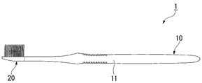
도 1은 본 실시형태에 의한 칫솔(1)의 정면도이다. 도 2는 칫솔(1)의 측면도이다. 칫솔(1)은 막대형상의 핸들체(10)와, 브러시 성형체(20)를 구비하고 있다. 핸들체(10)와 브러시 성형체(20)는 각각의 부재이다. 브러시 성형체(20)는 핸들체(10)에 착탈 가능하게 장착(꽂아 넣기) 가능하다.1 : is a front view of the toothbrush 1 which concerns on this embodiment. 2 is a side view of the toothbrush 1 . The toothbrush 1 is provided with the rod-
또한, 본 실시형태에 있어서의 정면이란 브러시 성형체(20)의 상면(21a)(상세한 것은 후술)의 법선 방향(이하에서는 간단히 법선 방향이라고 칭한다) 중 후술하는 필라멘트(23)가 돌출되는 측이다. 또한, 핸들부(11)의 길이 방향이며, 브러시 성형체(20)에 대해서 핸들체(10)가 꽂아 넣어지는 방향(이하, 간단히 꽂아 넣는 방향이라고 칭한다)은 상기 법선 방향과 직교한다. 상기 법선 방향과 꽂아 넣는 방향과 직교하는 방향은 브러시 성형체(20)의 폭 방향(이하, 간단히 폭 방향이라고 칭한다)이다.In addition, the front surface in this embodiment is the side from which the
도 3은 핸들체(10)의 정면도이다.3 is a front view of the
핸들체(10)는 도 3에 나타내는 바와 같이 막대형상의 핸들부(11)와, 핸들부(11)의 선단에 형성된 핸들부(11)의 길이 방향 선단측으로 돌출되는 삽입부(12)를 구비하고 있다. 칫솔(1)에서는 핸들체(10)의 삽입부(12)를 후술하는 브러시 성형체(20) 내에 꽂아 넣음으로써 삽입부(12)에 브러시 성형체(20)를 씌워서 부착하도록 되어 있다.As shown in FIG. 3 , the
본 실시형태의 핸들부(11)의 정면으로부터 볼 때 형상은 선단측으로부터 후단측을 향해서 서서히 폭이 좁아진 후에 일정한 폭으로 연장되고, 그 후에 서서히 폭이 넓어진 후에 좁아지도록 곡선적으로 변화된다. 핸들부(11)의 정면으로부터 볼 때 형상은 후단부가 대략 반원형상으로 되어 있다.When viewed from the front of the
핸들부(11)의 측면으로부터 볼 때 형상은 도 2에 나타내는 바와 같이 선단측으로부터 후단측을 향해서 일정한 폭으로 연장된 후에 손가락 접촉부가 되는 최대 두께까지 서서히 폭이 넓어진다. 핸들부(11)의 측면으로부터 볼 때 형상은 최대 두께의 손가락 접촉부로부터 후단측을 향해서 서서히 폭이 좁아지도록 곡선적으로 변화된다. 핸들부(11)의 측면으로부터 볼 때 형상은 후단부가 대략 반원형상으로 되어 있다.When viewed from the side of the
또한, 본 발명에 있어서 핸들부의 형상은 이 예의 형상에는 한정되지 않고, 강도, 조작성, 의장성 등을 고려해서 적당히 설정할 수 있다.In addition, in this invention, the shape of a handle part is not limited to the shape of this example, Considering intensity|strength, operability, designability, etc., it can set suitably.
핸들부(11)의 치수는 특별히 한정되지 않고, 적당히 설정할 수 있다. 예를 들면, 핸들부(11)의 길이는 100~200㎜로 할 수 있다.The dimension of the
삽입부(12)는 핸들체(10)에 브러시 성형체(20)를 부착한 상태에 있어서 브러시 성형체(20)로 피복되는 부분이다. 삽입부(12)의 후단은 핸들체(10)에 브러시 성형체(20)가 부착된 상태에 있어서의 브러시 성형체(20)의 후단 위치이다.The
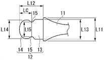
도 4는 삽입부(12)를 확대한 정면도이다. 도 5는 삽입부(12)를 확대한 측면도이다.4 is an enlarged front view of the
도 4에 나타내는 바와 같이 삽입부(12)는 핸들부(11)의 선단측에 형성된 기부(13)와, 기부(13)의 선단에 형성된 선단부(14)를 갖고 있다. 도 5에 나타내는 바와 같이 기부(13)와 선단부(14)는 정면측 및 배면측의 양측에서 핸들부(11)에 대하여 단차를 갖고 핸들부(11)보다 얇은 동일 두께로 형성되어 있다.As shown in FIG. 4 , the
기부(13)는 평면으로부터 볼 때 대략 직사각형상이다. 기부(13)는 폭 방향 양측에서 핸들부(11)에 대하여 단차를 갖고 핸들부(11)의 선단측의 최대 폭(L11)보다 좁은 폭(L13)으로 형성되어 있다(L13<L11). 선단부(14)는 폭 방향을 긴 지름 방향으로 하는 평면으로부터 볼 때 대략 타원형상이다. 선단부(14)는 대략 타원형상의 폭 방향 양측에서 삽입부(12)의 꽂아 넣는 방향과 평행한 직선으로 측 가장자리를 노치한 형상이다. 선단부(14)는 폭 방향 양측에서 기부(13)에 대하여 단차를 갖고 기부(13)의 폭(L13)보다 좁은 폭(L14)으로 형성되어 있다.The
삽입부(12)는 꽂아 넣는 방향의 대략 중앙이며, 기부(13)와 선단부(14) 사이에 함몰부(15)를 갖고 있다. 함몰부(15)는 폭 방향의 양측에 형성되어 있다. 함몰부(15)는 폭 방향에서 외측에 원호 중심을 갖고 내측으로 오목해지는 원호형상이다. 함몰부(15)끼리의 최단 거리(L15)는 기부(13)의 폭(L13) 및 선단부(14)의 폭(L14)보다 짧다. 선단부(14)에 있어서 폭(L14)을 규정하는 단 가장자리에 대한 함몰부(15)의 함몰량으로서는 일례로서 1㎜이다.The
내측으로 함몰된 함몰부(15)의 정점의 위치는 삽입부(12)의 꽂아 넣는 방향의 선단을 기점으로 하여 후단측에 삽입부(12)의 꽂아 넣는 방향의 최대 길이(L12)의 30% 이상, 70% 이하의 범위에 위치하는 것이 바람직하고, 40% 이상, 60% 이하의 범위에 위치하는 것이 보다 바람직하다. 또한, 함몰부(15)를 형성하는 영역 전체가 최대 길이(L12)의 30% 이상, 70% 이하의 범위에 위치하는 것이 바람직하고, 40% 이상, 60% 이하의 범위에 위치하는 것이 보다 바람직하다(상세한 것은 후술한다). 함몰부(15)의 폭 방향 내측으로의 최대 깊이(기부(13)에 있어서 폭(L13)을 규정하는 단 가장자리에 대한 함몰량)는 0.5㎜ 이상, 1.8㎜ 이하인 것이 바람직하고, 0.8㎜ 이상, 1.5㎜ 이하인 것이 보다 바람직하다(상세한 것은 후술한다).The position of the apex of the recessed
상기 함몰부(15)는 형상을 고안함으로써 브러시 성형체(20)와 핸들체(10)의 감합을 강고하게 하는 것이 가능하다. 함몰부(15)의 형상으로서 원호형상을 예시했지만 대략 직사각형이어도 좋고, 함몰부(15)의 삽입부 선단측에 소위 훅이 붙어있어도 좋다. 훅이란 함몰부(15)의 함몰 방향이 폭 방향 내측을 향해서 수직이 아니라 핸들부(11)측을 향해 기울어 함몰되는 형상이다.By designing the shape of the recessed
또한, 상기 함몰부(15)는 삽입부(12)의 폭 방향 양측에 내측으로 오목해지는 형상을 예시했지만, 외측으로 볼록해지는 형상이어도 좋다.In addition, although the said recessed
핸들체(10)는 경질 수지로 형성되어 있다.The
경질 수지로서는 일례로서 굽힘 탄성률(JIS K7171)이 1500㎫ 이상, 3000㎫ 이하인 수지를 예시할 수 있다. 구체적으로는, 예를 들면 폴리프로필렌 수지(PP), 폴리아세탈 수지(POM), 폴리에스테르 수지(PCTA), 폴리에틸렌테레프탈레이트 공중합체(PETG), 고밀도 폴리에틸렌(HDPE)을 예시할 수 있다. 이들 중에서도 비용면을 고려하면 범용 수지인 PP가 바람직하다.As an example of hard resin, resin whose flexural modulus (JIS K7171) is 1500 Mpa or more and 3000 Mpa or less can be illustrated. Specifically, polypropylene resin (PP), polyacetal resin (POM), polyester resin (PCTA), polyethylene terephthalate copolymer (PETG), and high density polyethylene (HDPE) can be illustrated, for example. Among these, PP, which is a general-purpose resin, is preferable in view of cost.
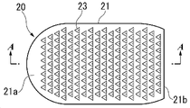
도 6은 브러시 성형체(20)의 정면도이다. 도 7은 도 6에 있어서의 A-A 단면도이다. 도 6 및 도 7에 나타내는 바와 같이 브러시 성형체(20)는 정면으로부터 볼 때 형상이 대략 직사각형상인 헤드 기대부(21)와, 헤드 기대부(21)의 정면에 형성된 복수의 필라멘트(23)를 구비하고 있다.6 is a front view of the brush molded
필라멘트(23)는 헤드 기대부(21)의 상면(21a)으로부터 정면측으로 돌출되는 대략 기둥형상이다. 필라멘트(23)는 기단측이 단면 대략 삼각형상인 대략 삼각 기둥형상이며, 선단측이 대략 삼각 기둥으로부터 연장되어 끝이 가늘어지는 삼각 뿔형상이다.The
필라멘트(23)의 끝이 가늘어지는 형상으로서는 테이퍼각의 변화점을 1개 이상 갖고, 선단으로부터 0~2㎜, 4~8㎜의 2개소에 변화점을 형성한 형상을 예시할 수 있다.Examples of the tapered shape of the
또한, 필라멘트(23)는 사각 뿔형상이어도 좋다. 필라멘트(23)가 사각 뿔형상이어도 테이퍼각의 변화점을 1개 이상 갖고, 선단으로부터 0~2㎜, 4~8㎜의 2개소에 변화점을 형성한 형상을 예시할 수 있다. 이 구성을 취함으로써 성형성을 확보하면서 청소성을 높이는 것이 가능해진다.In addition, the
필라멘트(23)는 브러시 성형체(20)의 폭 방향을 따라 배열되는 열이 꽂아 넣는 방향에서 이웃하는 열끼리가 반피치 어긋나도록 꽂아 넣는 방향을 따라 복수 열 형성되어 있다. 즉, 필라멘트(23)는 지그재그형상으로 배치되어 있다.The
도 8은 브러시 성형체(20)를 후단측으로부터 본 도면이다.8 is a view of the brush molded
도 8에 나타내는 바와 같이 필라멘트(23)는 폭 방향 중앙이 높고, 폭 방향 외측이 낮다.As shown in Fig. 8, the
필라멘트(23)는 폭 방향에서 고저차가 없는 플랫형상이어도 좋고, 고저가 역전해서 폭 방향 중앙이 낮고, 폭 방향 외측이 높아도 좋지만 폭 방향 중앙이 높은 돔형상으로 했을 경우에 구강 내의 청소성을 보다 높이는 것이 가능해진다. 필라멘트의 고저차로서는 0.5~3.0㎜인 것이 바람직하고, 0.5~2.0㎜인 것이 더 바람직하다.The
중앙의 필라멘트(23)가 위치하는 영역(필라멘트 기단의 폭 방향의 지름 폭(필라멘트 기단이 위치하는 폭 방향의 영역의 최대 폭))으로서는 필라멘트 전체가 차지하는 폭 방향의 길이의 20~45%인 것이 바람직하고, 25~40%인 것이 더 바람직하다.The area in which the
또한, 필라멘트의 배열 피치에 대해서는 길이 방향, 폭 방향 모두 0.5~1.5㎜인 것이 바람직하고, 0.8~1.2㎜인 것이 더 바람직하다.Moreover, about the arrangement pitch of a filament, it is preferable that it is 0.5-1.5 mm in both a longitudinal direction and a width direction, and it is more preferable that it is 0.8-1.2 mm.
필라멘트(23)의 최대 길이로서는 7㎜ 이상, 15㎜ 이하인 것이 바람직하고, 9㎜ 이상, 13㎜ 이하인 것이 보다 바람직하다. 필라멘트(23)의 최대 길이가 7㎜ 미만인 경우 구강 내의 청소성이 저하될 가능성이 있다. 필라멘트(23)의 최대 길이가 15㎜를 초과했을 경우 브러시 성형체(20)를 사출 성형에 의해 성형할 때의 이형성이 저하되어 버린다. 필라멘트(23)의 최대 길이를 7㎜ 이상, 15㎜ 이하로 함으로써 구강 내의 청소성 및 성형 시의 이형성을 확보할 수 있다.The maximum length of the
필라멘트(23)의 기단의 단면적으로서는 0.8㎟ 이하인 것이 바람직하고, 0.6㎟ 이하인 것이 보다 바람직하고, 0.4㎟ 이하인 것이 더 바람직하다.The cross-sectional area of the base end of the
필라멘트(23)의 기단의 단면적이 0.8㎟를 초과했을 경우 필라멘트(23)가 휘기 어려워져 치간이나 치경부 등의 간극 청소성이 저하될 가능성이 있다. 필라멘트(23)의 기단의 단면적을 0.8㎟ 이하로 함으로써 치간이나 치경부 등의 간극 청소성을 확보할 수 있다.When the cross-sectional area of the base end of the
헤드 기대부(21)의 상면(21a)의 면적에 대한 복수의 필라멘트(23)의 기단의 총단면적의 비율로서는 10% 이상, 50% 이하인 것이 바람직하다. 필라멘트(23)의 기단의 총단면적의 비율이 10% 미만인 경우 구강 내의 청소성이 저하될 가능성이 있다. 필라멘트(23)의 기단의 총단면적의 비율이 50%를 초과했을 경우 브러시 성형체(20)를 사출 성형에 의해 성형할 때의 이형성이 저하되어버린다. 필라멘트(23)의 기단의 총단면적의 비율 10% 이상, 50% 이하로 함으로써 구강 내의 청소성 및 성형 시의 이형성을 확보할 수 있다.The ratio of the total cross-sectional area of the base ends of the plurality of
필라멘트(23)의 단면형상으로서는 대략 삼각형 외에 대략 사각형 등의 대략 다각형이나, 대략 원형, 대략 성형(星形), 대략 주걱형 등을 선택 가능하다. 필라멘트(23)는 선단이 끝이 가늘어지는 테이퍼형상 외에 스트레이트형상으로 연장되는 구성이나 기단으로부터 앞이 가늘어지는 테이퍼형상이어도 좋다.As a cross-sectional shape of the
헤드 기대부(21)의 상면(21a)은 폭 방향 및 꽂아 넣는 방향과 평행한 평면이다. 상면(21a)은 필라멘트(23)의 돌출 방향에 관해서 필라멘트(23)의 기단의 위치와 동일 높이이다. 도 6 및 도 8에 나타내는 바와 같이 상면(21a)은 헤드 기대부(21)에 있어서의 외형 윤곽(최외 둘레)을 형성하고 있다. 즉, 상면(21a)은 브러시 성형체(20)를 사출 성형할 때의 파팅면이다.The
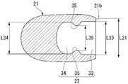
헤드 기대부(21)는 꽂아 넣는 방향으로 연장되어 후단측의 끝면(21b)에 개구하는 삽입 구멍(22)을 갖고 있다. 도 9는 삽입 구멍(22)을 포함하는 상면(21a)과 평행한 면에 있어서의 단면도이다. 도 9에 나타내는 바와 같이 삽입 구멍(22)은 끝면(21b)에 개구하는 제 1 부분(33)과, 제 1 부분(33)보다 안측에 위치하는 제 2 부분(34)을 갖고 있다. 도 7에 나타내는 바와 같이 제 1 부분(33)과 제 2 부분(34)은 헤드 기대부(21)보다 얇은 동일 두께로 형성되어 있다.The
헤드 기대부(21)는 삽입 구멍(22)에 있어서의 꽂아 넣는 방향의 대략 중앙이며, 제 1 부분(33)과 제 2 부분(34) 사이에 위치하는 돌기(35)를 갖고 있다. 돌기(35)는 삽입 구멍(22)의 폭 방향의 양측에 형성되어 있다. 돌기(35)는 삽입 구멍(22)에 삽입부(12)가 꽂아 넣어졌을 때에 함몰부(15)와 감합하는 위치에 각각 형성되어 있다. 돌기(35)는 폭 방향에서 외측에 원호 중심을 갖고 내측으로 볼록해지는 원호형상이다.The
헤드 기대부(21)의 후단측(끝면(21b))의 최대 폭(L21)은 핸들부(11)의 선단측의 최대 폭(L11)과 대략 동일하다.The maximum width L21 of the rear end side (
삽입 구멍(22)의 정면으로부터 볼 때 형상은 삽입부(12)의 정면으로부터 볼 때 형상과 대략 동일하다. 제 1 부분(33)의 폭(L33)은 삽입부(12)에 있어서의 기부(13)를 꽂아 넣기 가능한 길이이며, 기부(13)의 최대 폭(L13)과 대략 동일하다. 제 2 부분(34)의 폭(L34)은 삽입부(12)에 있어서의 선단부(14)가 꽂아 넣기 가능한 길이이며, 선단부(14)의 최대 폭(L14)과 대략 동일하다.The shape when viewed from the front of the
돌기(35)끼리의 최단 거리(L35)는 제 1 부분(33)의 폭(L33) 및 제 2 부분(34)의 폭(L34)보다 짧다. 돌기(35)끼리의 최단 거리(L35)는 삽입부(12)에 있어서의 선단부(14) 및 함몰부(15)가 꽂아 넣기 가능한 길이이며, 함몰부(15)끼리의 최단 거리(L15)와 대략 동일하다. 돌기(35)의 제 2 부분(34)에 대한 폭 방향 내측으로의 돌출량으로서는 일례로서 1㎜이다. 돌기(35)의 제 2 부분(34)에 대한 돌출량은 브러시 성형체(20)의 사출 성형 시에 삽입 구멍(22)을 성형하는 금형(슬라이드 코어)을 후단측으로 뽑을 때의 언더 컷량이다.The shortest distance L35 between the
또한, 핸들체(10)가 함몰부(15)의 삽입부 선단측에 훅을 갖고 있을 경우에는 브러시 성형체(20)와 핸들체(10)의 감합을 한층 강고하게 하는 것이 가능해진다.In addition, when the
도 7로 되돌아와서 헤드 기대부(21)의 상면(21a)과 배면측의 제 2 면(21c)의 최대 거리(최대 두께)(T)는 2.0㎜ 이상, 4.5㎜ 이하인 것이 바람직하다. 최대 거리(T)가 2.0㎜ 미만일 경우 상면(21a)과 삽입 구멍(22)의 상면(21a)측의 면 사이의 간극, 또는 제 2 면(21c)과 삽입 구멍(22)의 제 2 면(21c)측의 면 사이의 간극이 작아지며, 성형 시에 용융 수지의 유동성이 저하되기 때문에 수지가 미충전이 될 가능성이 있다. 최대 거리(T)가 4.5㎜를 초과했을 경우 브러시 성형체(20)를 구강 내에 삽입했을 때의 조작성이 저하될 가능성이 있다. 최대 거리(T)를 2.0㎜ 이상, 4.5㎜ 이하로 함으로써 수지의 충전성 및 브러시 성형체(20)를 구강 내에 삽입했을 때의 조작성을 확보할 수 있다.Returning to Fig. 7, it is preferable that the maximum distance (maximum thickness) T between the
헤드 기대부(21)의 폭 방향의 거리(최대 길이)로서는 특별히 한정되지 않지만, 예를 들면 10~16㎜이다. 특히, 헤드 기대부(21)의 폭 방향의 최대 길이가 13~16㎜일 경우 폭 넓은 와이드 헤드이면서 헤드부를 얇게 함으로써 구강 내 조작성을 확보할 수 있다.Although it does not specifically limit as a distance (maximum length) of the width direction of the
삽입 구멍(22)의 높이(t1)는 1.0㎜ 이상, 2.5㎜ 이하인 것이 바람직하다. 상면(21a)과 삽입 구멍(22)의 상면(21a)측의 면 사이의 헤드 기대부(21)의 두께(거리)(t2)는 0.5㎜ 이상, 2.0㎜ 이하인 것이 바람직하다. 헤드 기대부(21)의 배면측의 제 2 면(21c)과 삽입 구멍(22)의 제 2 면(21c)측의 면 사이의 헤드 기대부(21)의 두께(거리)(t3)는 0.5㎜ 이상, 2.0㎜ 이하인 것이 바람직하다.It is preferable that the height t1 of the
또한, 꽂아 넣는 방향의 헤드 기대부(21)의 최대 길이를 L1로 하고, 꽂아 넣는 방향의 삽입 구멍(22)의 최대 길이를 L2로 하면 L2/L1로 나타내어지는 헤드 기대부(21)의 최대 길이(L1)에 대한 삽입 구멍(22)의 최대 길이(L2)의 비율은 0.30 이상, 0.70 이하인 것이 바람직하고, 0.40 이상, 0.60 이하인 것이 보다 바람직하고, 0.45 이상, 0.55 이하인 것이 더 바람직하다.In addition, when the maximum length of the
L2/L1로 나타내어지는 값이 0.30 미만일 경우 경질 수지로 형성된 삽입부(12)의 존재하지 않는 영역이 커지기 때문에 브러시 성형체(20)의 전방이 굴곡되기 쉬워지며, 칫솔(1)의 사용성이 저하될 가능성이 있다. L2/L1이 0.70을 초과했을 경우 성형 시에 삽입 구멍(22)을 형성하는 금형(슬라이드 코어)이 점유하는 체적이 커지고, 수지 유동이 제한되기 때문에 필라멘트(23)의 성형성이 저하되어버린다. L2/L1로 나타내어지는 값을 0.30 이상, 0.70 이하로 함으로써 필라멘트(23)의 성형성 저하를 억제하면서 칫솔(1)의 사용성 저하를 억제할 수 있다.When the value expressed by L2/L1 is less than 0.30, the non-existent area of the
또한, L1-L2로 나타내어지는 삽입 구멍(22)의 선단측의 단부와 헤드 기대부(21)의 선단측의 단부의 거리는 5㎜ 이상, 15㎜ 이하인 것이 바람직하고, 8㎜ 이상, 12㎜ 이하인 것이 보다 바람직하다. L1-L2로 나타내어지는 값이 5㎜ 미만일 경우 수지 유동이 제한되기 때문에 필라멘트(23)의 성형성이 저하되어버린다. L1-L2로 나타내어지는 값이 15㎜ 초과했을 경우 경질 수지로 형성된 삽입부(12)의 존재하지 않는 영역이 커지기 때문에 브러시 성형체(20)의 전방이 굴곡되기 쉬워져 사용성이 저하될 가능성이 있다. L1-L2로 나타내어지는 값을 5㎜ 이상, 15㎜ 이하로 함으로써 필라멘트(23)의 성형성 저하를 억제하면서 칫솔(1)의 사용성 저하를 억제할 수 있다.Further, the distance between the tip end of the
브러시 성형체(20)에 있어서의 헤드 기대부(21)의 최대 두께(T)를 얇게 할 경우 상기 높이(t1), 두께(t2, t3)를 작게 하는 것이 생각되지만 두께(t2, t3)를 작게 할 경우에는 성형 시의 연질 수지의 유동성을 고려할 필요가 있다. 특히, 두께(t2)를 작게 하면 필라멘트(23)의 성형성에 큰 영향을 준다. 구체적으로는 두께(t2)를 작게 하면 브러시 성형체(20)를 성형하기 위한 금형에 있어서 필라멘트(23)를 향하는 연질 수지의 유로의 꽂아 넣는 방향과 직교하는 단면적이 작아지며, 쇼트 등의 성형 불량이 발생하기 쉬워져 필라멘트(23)의 성형성이 저하된다. 그 때문에 가장 선단측에 위치하는 필라멘트(23)의 기단과 헤드 기대부(21)의 배면의 최소 거리(S)로서는 1.5㎜ 이상, 3.0㎜ 이하인 것이 바람직하다.When the maximum thickness T of the
헤드 기대부(21)의 최소 두께로서는 1.0~2.5㎜인 것이 바람직하다. 헤드 기대부(21)의 최소 두께를 이 범위로 함으로써 헤드부 선단이 구강 내 조직에 접촉했을 때의 위화감을 경감하면서 구강 내 조작성을 높일 수 있다.As a minimum thickness of the
그래서 본 실시형태에서는 두께(t2)가 작을 경우에도 연질 수지의 유동성을 양호하게 하기 위해서 브러시 성형체(20)에 있어서의 삽입 구멍(22)보다 선단측에 삽입 구멍(22)(즉, 삽입 구멍(22)을 성형하는 금형(슬라이드 코어))이 존재하지 않는 일정한 영역이 형성되어 있다. 이에 따라 성형 시, 금형 내에서는 삽입 구멍(22)을 성형하기 위한 슬라이드 코어가 존재하지 않는 영역에 수지가 유동할 수 있기 때문에 슬라이드 코어의 존재에 기인하는 수지 유동성의 장해가 억제되어 필라멘트(23)의 성형성이 향상된다. 또한, 수지를 금형 내에 충전하기 위한 게이트 위치는, 예를 들면 헤드 기대부(21)의 선단을 선택할 수 있지만 특별히 한정은 되지 않는다.Therefore, in this embodiment, in order to improve the fluidity of the soft resin even when the thickness t2 is small, the insertion hole 22 (that is, the insertion hole 22) is formed in a certain area where the mold (slide core) forming the mold does not exist. Accordingly, during molding, since the resin can flow in the region where the slide core for molding the
게이트 위치는, 예를 들면 헤드 기대부(21)의 배면이나 후단에 배치하는 것도 가능하며, 게이트 절단의 잘린 조각(게이트흔)이 구강 내 조직을 손상한다는 문제를 회피할 수 있다.The gate position can also be arranged, for example, on the back or rear end of the
또한, 상술한 바와 같이 삽입부(12)에 함몰부(15)가 형성됨으로써 슬라이드 코어에는 함몰부(15)에 감합하는 돌기(35)를 성형하기 위한 오목부(35M)(도 10 참조)가 법선 방향으로 형성되게 된다. 이 오목부(35M)는 성형 시의 금형 내에서는 삽입 구멍(22)이 성형되는 슬라이드 코어의 배면측으로부터 정면측을 잇는 수지 유동의 유로를 구성한다. 통상, 슬라이드 코어가 차지하는 영역은 수지 유동이 제한되지만 돌기(35)를 성형하기 위한 오목부(35M)를 수지 유동의 유로로서 확보함으로써 필라멘트(23)의 성형성이 향상된다.In addition, as described above, since the recessed
또한, 상술한 바와 같이 함몰부(15)(돌기(35))가 삽입부(12)의 꽂아 넣는 방향의 선단을 기점으로 하여 후단측에 삽입부(12)의 꽂아 넣는 방향의 최대 길이(L12)의 30% 이상, 70% 이하, 바람직하게는 40% 이상, 60% 이하의 범위에 위치 함으로써 돌기(35)를 성형하기 위한 슬라이드 코어의 오목부(35M)가 삽입 구멍(22)의 꽂아 넣는 방향의 중앙 부근에 위치하게 된다. 돌기(35)의 위치가 삽입부(12)의 꽂아 넣는 방향에서 상기 범위 외에 있을 경우에는 성형 시의 수지 유동에 치우침이 발생하여 필라멘트(23)를 똑같이 성형할 수 없을 가능성이 있다. 돌기(35)의 위치를 삽입부(12)의 꽂아 넣는 방향에서 상기 범위 내로 함으로써 수지 유동의 치우침이 억제되어 필라멘트(23)를 똑같이 성형하는 것이 가능해진다.In addition, as described above, the maximum length L12 in the insertion direction of the recessed portion 15 (projection 35) in the insertion direction of the
또한, 함몰부(15)(돌기(35))의 폭 방향 내측으로의 최대 깊이(기부(13)에 대한 함몰량)는 0.5㎜ 이상, 1.8㎜ 이하인 것이 바람직하다(0.8㎜ 이상, 1.5㎜ 이하인 것이 보다 바람직하다). 함몰부(15)의 폭 방향 내측으로의 최대 깊이가 0.5㎜ 미만일 경우 오목부(35M)가 슬라이드 코어의 변 가장자리에만 형성되기 때문에 수지 유동성의 큰 향상을 기대할 수 없음과 아울러, 돌기(35)와의 감합이 약해져 칫솔(1)의 사용 시에 브러시 성형체(20)가 탈락할 가능성이 있다. 함몰부(15)의 폭 방향 내측으로의 최대 깊이가 1.8㎜를 초과했을 경우 돌기(35)와의 감합(언더 컷량)이 커지고, 이형 시에 삽입부(12)가 파단될 가능성이 있다. 함몰부(15)의 폭 방향 내측으로의 최대 깊이를 0.5㎜ 이상, 1.8㎜ 이하로 함으로써 수지 유동성의 향상, 브러시 성형체(20)의 탈락 억제 및 삽입부(12)의 파단 억제를 도모할 수 있다.In addition, it is preferable that the maximum depth (amount of depression with respect to the base part 13) in the width direction of the recessed part 15 (projection 35) inward is 0.5 mm or more and 1.8 mm or less (0.8 mm or more and 1.5 mm or less) is more preferable). When the maximum depth in the width direction of the recessed
또한, 핸들체(10)가 함몰부(15)의 삽입부 선단측에 훅을 갖고 있을 경우에는 브러시 성형체(20)와 핸들체(10)의 감합을 한층 강고하게 하는 것이 가능해진다.In addition, when the
헤드 기대부(21)는 배면(21c)의 선단측이 선단측을 향함에 따라 점차 정면측을 향해서 경사져서 점차 얇아지는 박육 영역(21d)을 갖는다. 도 7에 나타내는 바와 같이 박육 영역(21d)의 꽂아 넣는 방향의 최대 길이(L3)는 헤드 기대부(21)의 꽂아 넣는 방향의 최대 길이(L1)의 40% 이상인 것이 바람직하고, 50% 이상인 것이 보다 바람직하다.The
박육 영역(21d)의 최대 길이(L3)를 헤드 기대부(21)의 최대 길이(L1)의 40% 이상으로 함으로써 브러시 성형체(20)의 배면측의 체적을 감소할 수 있기 때문에 성형 시에 용융 수지를 상면(21a)측에 우선적으로 유동시킬 수 있고, 필라멘트(23)의 성형성을 향상시킬 수 있다. 이 효과는 게이트 위치가 헤드 기대부(21)의 선단에 배치될 경우에 의해 현저해진다. 박육 영역(21d)의 최대 길이(L3)가 헤드 기대부(21)의 최대 길이(L1)의 40% 미만일 경우에는 상기 성형성의 향상은 희박해질 가능성이 있다. 또한, 삽입부(12)와 삽입 구멍(22)의 감합 시 및 칫솔(1)의 사용 시에 연질 수지의 파손을 방지하는 점을 고려하면 헤드 기대부(21)의 배면(21c)으로부터 삽입부(12)의 배면까지의 거리(t3)는 0.5㎜ 이상 확보할 필요가 있다.By making the maximum length L3 of the
브러시 성형체(20)를 구성하는 연질 수지로서는 각종 엘라스토머를 사용할 수 있지만, 폴리우레탄인 것이 바람직하다.Although various elastomers can be used as a soft resin which comprises the brush molded
폴리우레탄은 스티렌계나 폴리에스테르계 등의 다른 엘라스토머에 비해 인장 강도가 높은 경향이 있기 때문에 연질 수지에 폴리우레탄을 사용함으로써 박육으로 해도 기계적인 강도를 확보할 수 있고, 삽입부(12)와 삽입 구멍(22)의 감합 시 및 칫솔(1)의 사용 시의 파손을 억제할 수 있다.Since polyurethane tends to have a higher tensile strength than other elastomers such as styrene or polyester, by using polyurethane for a soft resin, mechanical strength can be secured even if it is thin, and the
폴리우레탄 중에는 0.01~1.0wt%(질량%)의 C10 이상의 포화/불포화탄화수소, 고급 알콜, 지방산 아미드, 지방산 에스테르 저분자량 폴리에틸렌, 폴리에틸렌글리콜(PEG), 지방산 금속염, 장쇄 지방산, 지방산 글리세린, 실리콘 중 어느 하나 또는 복합해서 배합되어 활제, 이형제로서 기능한다.Polyurethane contains 0.01 to 1.0 wt% (mass%) of saturated/unsaturated hydrocarbons of C10 or higher, higher alcohols, fatty acid amides, fatty acid esters, low molecular weight polyethylene, polyethylene glycol (PEG), fatty acid metal salts, long chain fatty acids, fatty acid glycerin, silicone It functions as a lubricant and a mold release agent when combined alone or in combination.
또한, 폴리우레탄은 상기 외의 엘라스토머에 비해 선택할 수 있는 경도가 폭 넓고, 브러시 성형체(20)의 두께에 따라 그 사용성(예를 들면, 브러시 성형체 선단의 굴곡)을 고려한 수지 경도의 선택이 가능하다. 폴리우레탄의 경도로서는 쇼어 90A 이상, 70D 이하인 것이 바람직하다.In addition, polyurethane has a wide range of selectable hardness compared to other elastomers, and it is possible to select the resin hardness in consideration of usability (eg, curvature of the tip of the brush molded body) according to the thickness of the brush molded
폴리우레탄의 경도가 쇼어 90A보다 부드러울 경우 박육으로 형성되었을 때에 변형하기 쉬워지는 점에서 감합이 약해져서 칫솔(1)의 사용 시에 브러시 성형체(20)가 탈락하기 쉬워져버린다. 폴리우레탄의 경도가 쇼어 70D보다 단단할 경우 헤드 기대부(21)의 배면이 경사졌을 경우에 선단이 구강 조직에 닿았을 때에 통증이 발생할 가능성이 있다. 폴리우레탄의 경도를 쇼어 90A 이상, 70D 이하로 함으로써 칫솔(1)의 사용 시에 브러시 성형체(20)가 탈락하거나 헤드 기대부(21)의 선단이 닿았을 때에 통증이 발생하는 것을 억제할 수 있다.When the hardness of polyurethane is softer than Shore 90A, it is easy to deform when it is formed thin, so that the fit is weakened, and the brush molded
또한, 폴리우레탄으로서는 내수성과 항균성을 확보하는 관점으로부터 에테르계 폴리우레탄을 사용하는 것이 바람직하다.In addition, it is preferable to use an ether type polyurethane as a polyurethane from a viewpoint of ensuring water resistance and antibacterial property.
도 10은 브러시 성형체(20)를 성형하는 금형(MD)의 일례를 간략적으로 나타낸 단면도이다. 도 11은 몰드 클램핑 전의 금형(MD)을 간략적으로 나타낸 단면도이다.10 is a cross-sectional view schematically illustrating an example of a mold MD for molding the brush molded
금형(MD)은 개폐 방향(도 10 중, 상하 방향)으로 상대 이동하는 제 1 금형(MD1)과 제 2 금형(MD2)을 구비하고 있다. 제 1 금형(MD1)과 제 2 금형(MD2)은 상면(21a)과 동일 높이인 파팅면(PL)을 접합면으로 하여 몰드 클램핑된다.The mold MD is provided with the 1st mold MD1 and the 2nd mold MD2 which relatively move in the opening-and-closing direction (up-down direction in FIG. 10). The first mold MD1 and the second mold MD2 are mold-clamped using the parting surface PL having the same height as the
제 1 금형(MD1)은 사출 성형기의, 예를 들면 고정측에 부착되고, 사출 성형기로부터 용융 수지가 충전된다. 제 2 금형(MD2)은 사출 성형기의, 예를 들면 가동측에 부착되고, 제 1 금형(MD1)에 대하여 상기 개폐 방향으로 이동함으로써 금형(MD)도 개폐가 행해진다.The first mold MD1 is attached to, for example, a stationary side of an injection molding machine, and is filled with molten resin from the injection molding machine. The second mold MD2 is attached to, for example, a movable side of the injection molding machine, and the mold MD is also opened and closed by moving in the opening/closing direction with respect to the first mold MD1.
제 1 금형(MD1)은 몰드 클램핑되어 제 2 금형(MD2)과 접합했을 때에 상면(21a)이 성형되는 성형면(21aM)과, 필라멘트(23)가 성형되는 캐비티(23M)를 갖고 있다.The first mold MD1 has a molding surface 21aM on which the
제 2 금형(MD2)은 몰드 클램핑되어 제 1 금형(MD1)과 접합했을 때에 헤드 기대부(21)가 성형되는 캐비티(21M)와, 캐비티(21M)의 선단측에 개구하고, 캐비티(21M)에 용융 수지가 도입되는 게이트부(G)와, 꽂아 넣는 방향에 있어서 끝면(21b)의 위치에 형성되고, 꽂아 넣는 방향과 직교하는 접촉면(21eM)을 갖고 있다. 게이트부(G)로서는, 예를 들면 사이드 게이트 방식이 사용되지만 핀포인트 게이트 방식, 터널 게이트 방식을 사용해도 좋다. 접촉면(21eM)은 제 2 금형(MD2)에 있어서 헤드 기대부(21)에 있어서의 배면을 성형하는 위치로부터 PL면과 떨어지는 방향으로 연장되어 있다.The second mold MD2 has a
제 2 금형(MD)에는 슬라이드 코어(SL)가 형성되어 있다. 슬라이드 코어(SL)는 삽입 구멍(22)이 성형되는 코어부(22M)와, 코어부(22M)가 돌출되어 꽂아 넣는 방향과 직교하는 성형면(21bM)을 갖고 있다. 도 11에 나타내는 바와 같이 몰드 클램핑 전에 있어서 성형면(21bM)은 접촉면(21eM)과 떨어져 있다. 슬라이드 코어(SL)는 제 1 금형(MD1)과 제 2 금형(MD2)이 몰드 클램핑되었을 때에 도 10에 나타내는 바와 같이 성형면(21bM)의 일부가 접촉면(21eM)과 접촉하고, 코어부(22M)가 캐비티(21M)에 삽입되는 위치에 위치 결정된다. 성형면(21bM) 중, 접촉면(21eM)과 접촉하지 않고 캐비티(21M)에 면하는 영역은 끝면(21b)을 성형하는 영역이다. 또한, 슬라이드 코어(SL)는 제 1 금형(MD1)과 제 2 금형(MD2)이 몰드 개방했을 때에 성형된 브러시 성형체(20)의 이형에 코어부(22M)가 지장을 초래하지 않도록 코어부(22M)가 캐비티(21M)로부터 이탈하는 방향으로 이동한다. 슬라이드 코어(SL)의 이동 방향은 자체 중량에 의한 불측의 이동을 회피하기 위해서 수평 방향인 것이 바람직하다.A slide core SL is formed in the second mold MD. The slide core SL has a
상기 금형(MD)의 구성은 슬라이드 코어(SL)에 의해 브러시 성형체(20)의 삽입 구멍(22)을 형성하는 것을 예시했지만, 금형(MD)에 핸들체(10)을 삽입하고, 브러시 성형체(20)를 2차 성형하는 제조 방법도 선택할 수 있다. 그 경우에는 브러시 성형체(20)와 핸들체(10)를 착탈 가능하게 하는 것이 불리해지지만 성형 후에 핸들체(10)와 브러시 성형체(20)를 감합하는 후공정을 생략할 수 있다.Although the configuration of the mold MD exemplifies that the
슬라이드 코어(SL)의 선단측의 배면은 헤드 기대부(21)의 경사 배면과 접근하기 때문에 R 모따기 가공이나 C 모따기 가공을 실시함으로써 슬라이드 코어(SL)의 이탈 시나 핸들체(10)의 삽입부(12)와의 감합 시에 헤드 기대부(21)의 파손(수지의 찢어짐)을 방지하는 것이 가능해진다. R 모따기 가공이나 C 모따기 가공의 치수로서는 1.5㎜ 이상인 것이 바람직하고, 3.0㎜ 이상인 것이 더 바람직하다.Since the rear surface on the tip side of the slide core SL approaches the inclined rear surface of the
상기 금형(MD)에 있어서 제 1 금형(MD1)과 제 2 금형(MD2)이 몰드 클램핑된 상태로 게이트부(G)로부터 캐비티(21M)에 도입된 용융 수지는 캐비티(21M)에 있어서의 코어부(22M)보다 선단측에 충분한 용적이 확보되어 있는 것 및 캐비티(21M)의 선단측에 있어서 배면측이 경사져서 얇아져 있음으로써 캐비티(21M)의 선단측에 도입된 용융 수지를 상면(21a)측으로 우선적으로 유동시킬 수 있고, 충분한 충전압에 의해 캐비티(23M)에 용융 수지를 충전할 수 있다.In the mold MD, the molten resin introduced into the
또한, 캐비티(21M)에 있어서 코어부(22M)의 배면측에 도입된 용융 수지는 코어부(22M)의 꽂아 넣는 방향의 중앙 부근에 형성된 오목부(35M)를 유로로서 정면측으로 유동할 수 있기 때문에 꽂아 넣는 방향에서 수지 유동의 치우침을 억제한 상태로 필라멘트(23)를 똑같이 성형하는 것이 가능하다.In addition, in the
이상 설명한 바와 같이 본 실시형태의 칫솔(1)에서는 감합 구조의 브러시 성형체(20)를 사용하여 헤드 기대부(21)의 두께를 2.0㎜ 이상, 4.5㎜ 이하로 얇게 한 경우에도 수지 유동성이 저하되는 일 없이 브러시 성형체(20)를 성형해서 구강 내 조작성이 우수한 칫솔(1)을 제공하는 것이 가능해진다.As described above, in the toothbrush 1 of this embodiment, the resin fluidity decreases even when the thickness of the
[실시예][Example]
이하, 실시예를 나타내서 본 발명을 상세하게 설명하지만 본 발명은 이하의 실시예에 한정되는 것은 아니고, 그 요지를 일탈하지 않는 범위에서 적당히 변경해서 실시할 수 있다.Hereinafter, although an Example is shown and this invention is demonstrated in detail, this invention is not limited to a following Example, The range which does not deviate from the summary can be changed suitably and can be implemented.
(실시예 1~7, 비교예 1~2)(Examples 1-7, Comparative Examples 1-2)
[표 1]에 나타내는 수단에 따라 상술한 필라멘트의 기단과 헤드 기대부의 배면의 최대 거리; T, 필라멘트의 기단과 헤드 기대부의 배면의 최소 거리; S, 삽입 구멍의 높이; t1, 헤드 기대부의 최대 길이; L1, 삽입 구멍의 최대 길이; L2, 헤드 기대부의 최대 길이(L1)에 대한 삽입 구멍의 최대 길이(L2)의 비율; L2/L1, 헤드 기대부의 최대 길이(L1)와 삽입 구멍의 최대 길이(L2)의 차; L1-L2, 박육 영역의 최대 길이; L3, 최대 길이(L1)에 대한 최대 길이(L3)의 비율; L3/L1, 함몰부의 유무, 삽입부 선단을 기점으로 한 함몰부의 위치; LC, 삽입부(12)의 꽂아 넣는 방향의 최대 길이(L12)(삽입 구멍의 최대 길이(L2))에 대한 함몰부의 위치(LC)의 비율; LC/L12(LC/L2) 중 적어도 하나가 상이한 칫솔을 실시예 1~7, 비교예 1~2의 샘플로 했다. 각 샘플을 구성하는 수지는 폴리우레탄으로 했다.Maximum distance between the base end of the above-mentioned filament and the back surface of the head base according to the means shown in Table 1; T, the minimum distance between the base of the filament and the back of the base of the head; S, the height of the insertion hole; t1, the maximum length of the head base; L1, the maximum length of the insertion hole; L2, the ratio of the maximum length (L2) of the insertion hole to the maximum length (L1) of the head base; L2/L1, the difference between the maximum length of the head base (L1) and the maximum length of the insertion hole (L2); L1-L2, the maximum length of the thin region; L3, the ratio of the maximum length (L3) to the maximum length (L1); L3/L1, the presence or absence of the depression, the position of the depression with the tip of the insertion portion as a starting point; LC, the ratio of the position LC of the depression to the maximum length L12 in the insertion direction of the insertion portion 12 (the maximum length L2 of the insertion hole); The toothbrush from which at least 1 differs in LC/L12 (LC/L2) was made into the sample of Examples 1-7 and Comparative Examples 1-2. Resin constituting each sample was polyurethane.
[평가 방법][Assessment Methods]
실시예 1~7, 비교예 1~2의 각 샘플에 대해서는 필라멘트의 성형성, 브러시 성형체의 굴곡의 하기 어려움, 구강 내 전체의 닦기 용이함 각각에서 평가했다.Each of the samples of Examples 1 to 7 and Comparative Examples 1 and 2 was evaluated in terms of filament moldability, difficulty in bending the brush molded body, and ease of wiping the entire oral cavity.
(1) 필라멘트의 성형성의 평가 방법(1) Method for evaluating the moldability of filaments
동 조건에 의해 성형한 5개의 브러시 성형체를 이하의 기준에서 평가했다.Five brush molded articles molded under the same conditions were evaluated on the basis of the following criteria.
5점: 외관의 불량이 전혀 확인되지 않는다.5 points|pieces: The defect of an external appearance is not recognized at all.
4점: 필라멘트 선단이 이형 시에 변형된다(압력이 충분히 부하되지 않았기 때문에 이형 시의 외력으로 구부러져버린다).4 points|pieces: The tip of a filament deform|transforms at the time of release (because the pressure is not fully applied, it will bend by the external force at the time of release).
3점: 필라멘트 선단의 굵기가 설계값보다 얇다.3 points: The thickness of the tip of the filament is thinner than the design value.
2점: 필라멘트의 길이가 설계값보다 짧다(모든 필라멘트가 전체 길이의 반분 이상).2 points: The length of the filament is shorter than the design value (all filaments are more than half of the total length).
1점: 필라멘트의 길이가 설계값보다 짧다(전체 길이의 반분 미만의 필라멘트가 존재).1 point: The length of the filament is shorter than the design value (less than half of the total length of the filament exists).
그리고 5개의 평가점의 평균값을 구하고, 이하의 4단계에 의한 평가를 행했다.And the average value of five evaluation points was calculated|required, and evaluation by the following four steps was performed.
◎(double circle mark): 4.5 이상, 5.0점 이하.◎ (double circle mark): 4.5 or more, 5.0 or less.
○(circle mark): 3.5 이상, 4.5점 미만.○ (circle mark): 3.5 or more and less than 4.5 points.
△(triangle mark): 2.5 이상, 3.5점 미만.△ (triangle mark): 2.5 or more and less than 3.5 points.
×(cross mark): 2.5점 미만.× (cross mark): less than 2.5 points.
(2) 브러시 성형체의 굴곡의 하기 어려움의 평가 방법(2) Evaluation method for the difficulty of bending the brush molded body
10명의 전문 패널에 의한 관능 평가를 행하고, 이닦을 때의 브러시 성형체 전방의 굴곡의 하기 어려움을 이하의 기준에서 평가했다.The sensory evaluation by 10 expert panelists was performed, and the following criteria evaluated the difficulty of bending the front side of the brush molded object at the time of tooth brushing.
5점: 매우 굴곡하기 어렵다.5 points|pieces: It is very difficult to bend|fold.
4점: 약간 굴곡하기 어렵다.4 points|pieces: It is slightly hard to bend|fold.
3점: 어느 쪽도 아니다.3 points: Neither.
2점: 약간 굴곡하기 쉽다.2 points|pieces: It is easy to bend slightly.
1점: 매우 굴곡하기 쉽다.1 point|piece: It is very easy to bend|fold.
그리고 10명의 전문 패널에 의한 평가점의 평균값을 구하고, 이하의 4단계에 의한 평가를 행했다.And the average value of the evaluation points by the expert panel of 10 was calculated|required, and evaluation by the following four steps was performed.
◎: 4.5 이상, 5.0점 이하.(double-circle): 4.5 or more, 5.0 points|pieces or less.
○: 3.5 이상, 4.5점 미만.○: 3.5 or more and less than 4.5 points.
△: 2.5 이상, 3.5점 미만.(triangle|delta): 2.5 or more and less than 3.5 points|pieces.
×: 2.5점 미만.x: less than 2.5 points.
(3) 구강 내 전체의 닦기 용이함의 평가 방법(3) Evaluation method for the ease of wiping the entire oral cavity
10명의 전문 패널에 의한 관능 평가를 행하고, 이닦을 때의 구강 내 전체의 닦기 용이함(특히, 어금니의 닦기 용이함을 중시)을 이하의 기준에서 평가했다.The sensory evaluation by the expert panel of 10 people was performed, and the following criteria evaluated the easiness of wiping (particularly, focusing on easiness of wiping of a molar) of the whole oral cavity at the time of tooth brushing.
5점: 매우 닦기 쉽다.5 points|pieces: It is very easy to wipe.
4점: 약간 닦기 쉽다.4 points|pieces: It is slightly easy to wipe.
3점: 어느 쪽도 아니다.3 points: Neither.
2점: 약간 닦기 어렵다.2 points|pieces: It is slightly difficult to wipe.
1점: 매우 닦기 어렵다.1 point|piece: It is very difficult to polish.
그리고 10명의 전문 패널에 의한 평가점의 평균값을 구하고, 이하의 4단계에 의한 평가를 행했다.And the average value of the evaluation points by 10 expert panel was calculated|required, and evaluation by the following four steps was performed.
◎: 4.5 이상, 5.0점 이하.(double-circle): 4.5 or more, 5.0 points|pieces or less.
○: 3.5 이상, 4.5점 미만.○: 3.5 or more and less than 4.5 points.
△: 2.5 이상, 3.5점 미만.(triangle|delta): 2.5 or more and less than 3.5 points|pieces.
×: 2.5점 미만.x: less than 2.5 points.

[표 1]에 나타내는 바와 같이 필라멘트의 기단과 헤드 기대부의 배면의 최대 거리(T)가 2.0㎜ 이상, 4.5㎜ 이하이며, 또한 헤드 기대부의 최대 길이(L1)에 대한 삽입 구멍의 최대 길이(L2)의 비율인 L2/L1이 0.30 이상, 0.70 이하인 실시예 1~7에 대해서는 필라멘트의 성형성, 브러시 성형체의 굴곡의 하기 어려움, 구강 내 전체의 닦기 용이함의 전체에서 양호한 결과가 얻어졌다.As shown in [Table 1], the maximum distance (T) between the base end of the filament and the back surface of the head base part is 2.0 mm or more and 4.5 mm or less, and the maximum length (L2) of the insertion hole relative to the maximum length (L1) of the head base part ), in Examples 1 to 7, where L2/L1 was 0.30 or more and 0.70 or less, good results were obtained in terms of filament formability, difficulty in bending the brush molded body, and ease of wiping the entire oral cavity.
이에 대하여 헤드 기대부의 최대 길이(L1)에 대한 삽입 구멍의 최대 길이(L2)의 비율인 L2/L1이 0.30 미만인 비교예 1에 대해서는 브러시 성형체의 굴곡의 하기 어려움에 관해서 양호한 결과가 얻어지지 않았다. 또한, 헤드 기대부의 최대 길이(L1)에 대한 삽입 구멍의 최대 길이(L2)의 비율인 L2/L1이 0.70을 초과한 비교예 2에 대해서는 필라멘트의 성형성에 관해서 양호한 결과가 얻어지지 않았다.On the other hand, in Comparative Example 1 in which L2/L1, which is the ratio of the maximum length L2 of the insertion hole to the maximum length L1 of the head base, was less than 0.30, good results were not obtained regarding the difficulty in bending the brush molded body. Further, in Comparative Example 2 in which L2/L1, which is the ratio of the maximum length L2 of the insertion hole to the maximum length L1 of the head base, exceeded 0.70, good results were not obtained regarding the moldability of the filament.
또한, 헤드 기대부의 최대 길이(L1)에 대한 박육 영역의 최대 길이(L3)의 비율인 L3/L1이 40% 미만인 실시예 4~5에 대해서는 필라멘트의 성형성 및 구강 내 전체의 닦기 용이함에 관해서 실시예 1만큼은 양호한 결과가 얻어지지 않았다.In addition, for Examples 4 to 5, in which L3/L1, which is the ratio of the maximum length (L3) of the thin region to the maximum length (L1) of the head base, is less than 40%, regarding the moldability of the filament and the ease of wiping the entire oral cavity As good as Example 1 was not obtained.
또한, 삽입부 선단을 기점으로 한 함몰부의 중심 위치(LC)가 3㎜ 미만이며, 삽입부(12)의 꽂아 넣는 방향의 최대 길이(L12)(삽입 구멍의 최대 길이(L2))에 대한 함몰부의 위치(LC)의 비율인 LC/L12(LC/L2)의 비율이 30% 미만인 실시예 6과, 삽입부 선단을 기점으로 한 함몰부의 중심 위치(LC)가 7㎜를 초과하고, 삽입부(12)의 꽂아 넣는 방향의 최대 길이(L12)(삽입 구멍의 최대 길이(L2))에 대한 함몰부의 위치(LC)의 비율인 LC/L12(LC/L2)의 비율이 70% 이상인 실시예 7에 대해서는 필라멘트의 성형성에 관해서 실시예 1만큼은 양호한 결과가 얻어지지 않았다.In addition, the central position LC of the depression with the tip of the insertion portion as a starting point is less than 3 mm, and the
또한, L1-L2로 나타내어지는 헤드 기대부의 최대 길이(L1)와 삽입 구멍의 최대 길이(L2)의 차가 15㎜를 초과하는 비교예 1에 대해서는 브러시 성형체의 굴곡의 하기 어려움에 관해서 양호한 결과가 얻어지지 않았던 것에 추가하여 구강 내 전체의 닦기 용이함에 관해서 실시예 1만큼은 양호한 결과가 얻어지지 않았다.Also, in Comparative Example 1, in which the difference between the maximum length L1 of the head base, represented by L1-L2, and the maximum length L2 of the insertion hole, exceeds 15 mm, good results were obtained regarding the difficulty in bending the brush molded body. In addition to the fact that it did not lose, the result as good as Example 1 was not obtained with respect to the easiness of wiping the whole oral cavity.
이상, 첨부된 도면을 참조하면서 본 발명에 의한 적합한 실시형태에 대해서 설명했지만 본 발명은 이러한 예에 한정되지 않는 것은 말할 필요도 없다. 상술한 예에 있어서 나타낸 각 구성 부재의 여러 형상이나 조합 등은 일례이며, 본 발명의 주지로부터 일탈하지 않는 범위에 있어서 설계 요구 등에 의거하여 여러 가지 변경 가능하다.As mentioned above, although preferred embodiment by this invention was demonstrated referring an accompanying drawing, it cannot be overemphasized that this invention is not limited to this example. The various shapes, combinations, etc. of each structural member shown in the above-mentioned example are an example, In the range which does not deviate from the main point of this invention, various changes are possible based on a design request etc.
예를 들면, 상기 실시형태에서는 헤드 기대부(21)에 있어서의 외형 윤곽(최외 둘레)을 형성하는 상면(21a)과 필라멘트(23)의 기단이 동일 높이이며, 필라멘트(23)가 상면(21a)으로부터 돌출되는 구성을 예시했지만 이 구성에 한정되지 않는다.For example, in the above embodiment, the
예를 들면, 상면(21a)에 헤드 기대부(21)에 있어서의 외형 윤곽보다 내측에 위치하고, 일정한 두께로 상면(21a)으로부터 돌출되는 토대부를 형성하고, 필라멘트(23)가 상면(21a)이 아니라 토대부의 상면으로부터 돌출되는(토대부의 상면과 필라멘트(23)의 기단이 동일 높이인) 구성이어도 좋다. 이 경우 토대부의 두께 만큼 브러시 성형체(20)가 두꺼워지기 때문에 파팅면(PL)이 되는 상면(21a)과 필라멘트(23)의 기단이 동일 높이인 것이 바람직하다. 토대부를 형성하지 않을 경우에는 토대부를 형성하는 경우와 비교해서 수지의 유동성이 낮아지기 때문에 본 발명의 작용이 보다 현저해진다.For example, the
또한, 상기 실시형태에서는 핸들체(10)가 경질 수지로 형성된 구성을 예시했지만 이 구성에 한정되지 않고, 예를 들면 핸들체(10)의 일부(핸들부(10) 등)가 연질 수지로 피복된 구성이어도 좋다. 이 구성을 취했을 경우 장식성 및 그립성을 향상시킬 수 있다.In addition, in the said embodiment, although the structure in which the
(산업상 이용가능성)(industrial applicability)
본 발명은 칫솔에 적용할 수 있다.The present invention is applicable to toothbrushes.
1: 칫솔
10: 핸들체
11: 핸들부
12: 삽입부
15: 함몰부
20: 브러시 성형체
21: 헤드 기대부
21a: 상면(파팅면)
21c: 배면
21d: 박육 영역
22: 삽입 구멍
23: 필라멘트
35: 돌기1: Toothbrush
10: handle body
11: handle part
12: insert
15: depression
20: brush molded body
21: head base
21a: upper surface (parting surface)
21c: back
21d: thin area
22: insertion hole
23: filament
35: turn
Claims (7)
연질 수지로 형성되어 상기 핸들체의 선단측에 형성된 브러시 성형체를 구비하고,
상기 핸들체는 선단측으로 돌출되어 형성된 삽입부를 갖고,
상기 브러시 성형체는 헤드 기대부와, 상기 헤드 기대부의 정면측으로 돌출되는 필라멘트를 갖고,
상기 헤드 기대부는 상기 삽입부가 꽂아 넣어져서 감합하는 삽입 구멍을 갖고,
상기 브러시 성형체는 상기 필라멘트의 기단과 헤드 기대부의 배면의 최대 거리가 2.0㎜ 이상, 4.5㎜ 이하이며,
꽂아 넣는 방향의 상기 헤드 기대부의 최대 길이를 L1로 하고,
상기 꽂아 넣는 방향의 상기 삽입 구멍의 최대 길이를 L2로 하면,
L2/L1로 나타내어지는 상기 헤드 기대부의 최대 길이에 대한 상기 삽입 구멍의 최대 길이의 비율은 0.30 이상, 0.70 이하인 것을 특징으로 하는 칫솔.A handle body formed of a hard resin;
and a brush molded body formed of a soft resin and formed on the tip side of the handle body;
The handle body has an insertion portion formed to protrude toward the front end,
The brush molded body has a head base and a filament protruding toward the front side of the head base,
The head base portion has an insertion hole into which the insertion portion is inserted and fitted,
In the brush molded body, the maximum distance between the base end of the filament and the back surface of the head base portion is 2.0 mm or more and 4.5 mm or less,
Let L1 be the maximum length of the head base in the insertion direction,
If the maximum length of the insertion hole in the insertion direction is L2,
A toothbrush, characterized in that the ratio of the maximum length of the insertion hole to the maximum length of the head base, represented by L2/L1, is 0.30 or more and 0.70 or less.
L1-L2로 나타내어지는 상기 삽입 구멍의 상기 선단측의 단부와 상기 헤드 기대부의 상기 선단측의 단부의 거리는 5㎜ 이상, 15㎜ 이하인 칫솔.The method of claim 1,
The distance between the edge part on the said tip side of the said insertion hole represented by L1-L2 and the edge part on the said tip side of the said head base part is 5 mm or more and 15 mm or less.
상기 헤드 기대부는 상기 배면의 상기 선단측이 상기 선단측을 향함에 따라 점차 상기 정면측을 향해서 경사져서 점차 얇아지는 박육 영역을 갖고,
상기 박육 영역의 상기 꽂아 넣는 방향의 최대 길이는 상기 헤드 기대부의 상기 꽂아 넣는 방향의 최대 길이의 40% 이상인 칫솔.3. The method of claim 1 or 2,
The head base portion has a thin area that gradually becomes thinner by gradually inclining toward the front side as the front end side of the rear surface faces the front end side,
The maximum length in the insertion direction of the thin region is 40% or more of the maximum length in the insertion direction of the head base portion.
상기 삽입부는 상기 필라멘트의 돌출 방향과 직교하는 방향의 단 가장자리에 내측으로 오목해지는 적어도 1개 이상의 함몰부를 갖고,
상기 헤드 기대부는 상기 삽입 구멍에 상기 삽입부가 꽂아 넣어졌을 때에 상기 함몰부와 감합하는 위치에 돌기를 갖는 칫솔.4. The method according to any one of claims 1 to 3,
The insertion portion has at least one recessed portion concave inwardly at the end edge in a direction orthogonal to the protruding direction of the filament,
A toothbrush having a projection at a position where the head base portion engages the depression portion when the insertion portion is inserted into the insertion hole.
상기 함몰부는 상기 필라멘트의 돌출 방향 및 상기 꽂아 넣는 방향과 직교하는 폭 방향의 단 가장자리에 형성되고, 또한 상기 삽입부의 상기 꽂아 넣는 방향의 선단을 기점으로 하여 후단측에 상기 삽입부의 상기 꽂아 넣는 방향의 최대 길이 30% 이상, 70% 이하의 범위에 위치하는 칫솔.5. The method of claim 4,
The recessed portion is formed at an end edge in the width direction orthogonal to the protrusion direction of the filament and the insertion direction, and the insertion direction of the insertion unit is formed at the rear end with the tip of the insertion portion as a starting point. Toothbrush positioned at a maximum length of 30% or more and 70% or less.
상기 연질 수지는 폴리우레탄인 칫솔.6. The method according to any one of claims 1 to 5,
The soft resin is polyurethane toothbrush.
상기 필라멘트의 돌출 방향에 관해서 상기 필라멘트의 기단의 위치는 상기 브러시 성형체의 파팅면의 위치와 동일한 칫솔.7. The method according to any one of claims 1 to 6,
The position of the proximal end of the filament with respect to the projection direction of the filament is the same as the position of the parting surface of the brush molded body.
Applications Claiming Priority (3)
| Application Number | Priority Date | Filing Date | Title |
|---|---|---|---|
| JP2019231982 | 2019-12-23 | ||
| JPJP-P-2019-231982 | 2019-12-23 | ||
| PCT/JP2020/044628 WO2021131526A1 (en) | 2019-12-23 | 2020-12-01 | Toothbrush |
Publications (1)
| Publication Number | Publication Date |
|---|---|
| KR20220120557A true KR20220120557A (en) | 2022-08-30 |
Family
ID=76573894
Family Applications (1)
| Application Number | Title | Priority Date | Filing Date |
|---|---|---|---|
| KR1020227017246A KR20220120557A (en) | 2019-12-23 | 2020-12-01 | toothbrush |
Country Status (7)
| Country | Link |
|---|---|
| US (1) | US20220400843A1 (en) |
| EP (1) | EP4082388A4 (en) |
| JP (1) | JPWO2021131526A1 (en) |
| KR (1) | KR20220120557A (en) |
| CN (2) | CN114760881A (en) |
| TW (1) | TW202123845A (en) |
| WO (1) | WO2021131526A1 (en) |
Families Citing this family (4)
| Publication number | Priority date | Publication date | Assignee | Title |
|---|---|---|---|---|
| WO2021131526A1 (en) * | 2019-12-23 | 2021-07-01 | ライオン株式会社 | Toothbrush |
| US11877645B2 (en) | 2021-05-14 | 2024-01-23 | Colgate-Palmolive Company | Personal care implement |
| JP2023091379A (en) * | 2021-12-20 | 2023-06-30 | ライオン株式会社 | Brush molded body and toothbrush |
| WO2023120163A1 (en) * | 2021-12-22 | 2023-06-29 | ライオン株式会社 | Brush molded body, and toothbrush |
Citations (3)
| Publication number | Priority date | Publication date | Assignee | Title |
|---|---|---|---|---|
| JPS61207233A (en) | 1985-03-13 | 1986-09-13 | Kubota Ltd | Traveling gear |
| CN204561298U (en) | 2015-04-24 | 2015-08-19 | 郑超 | A kind of environmental protection Rhizoma Sparganii cone bristle cleans the one-body molded head toothbrushes of tongue fur |
| CN107041792A (en) | 2017-02-08 | 2017-08-15 | 河源唯缇科技有限公司 | A kind of socket joint type bristle covers toothbrush device |
Family Cites Families (15)
| Publication number | Priority date | Publication date | Assignee | Title |
|---|---|---|---|---|
| JPS61207233U (en) | 1985-06-14 | 1986-12-27 | ||
| US5369831A (en) * | 1991-03-25 | 1994-12-06 | Sonex International Corporation | Therapeutic ultrasonic toothbrush |
| DE4136537C1 (en) * | 1991-11-06 | 1993-01-21 | Johnson & Johnson Ag, Spreitenbach, Ch | |
| US5722043A (en) * | 1993-02-05 | 1998-02-24 | The Research Foundation Of State University Of New York | Method and apparatus of assigning and sharing channels in a cellular communication system |
| US20020112302A1 (en) * | 1994-09-16 | 2002-08-22 | Susan Harrison | Child's utensil |
| WO2000049911A1 (en) * | 1999-02-24 | 2000-08-31 | Susumu Inoue | Rubber-nylon-mixture bristle toothbrush |
| JP2003144228A (en) * | 2001-11-13 | 2003-05-20 | Asahi Irika Kk | Toothbrush wherein brush section can be replaced |
| JP2003153741A (en) * | 2001-11-22 | 2003-05-27 | Matsushita Electric Works Ltd | Gum massaging brush and gum massaging device |
| JP4628956B2 (en) * | 2003-10-29 | 2011-02-09 | ライオン株式会社 | toothbrush |
| JP2010194044A (en) * | 2009-02-24 | 2010-09-09 | Sunstar Inc | Toothbrush and its manufacturing method |
| JP5993555B2 (en) * | 2011-08-09 | 2016-09-14 | ライオン株式会社 | toothbrush |
| CN111449408B (en) * | 2014-09-01 | 2023-09-08 | 狮王株式会社 | Toothbrush with tooth brush |
| SG10202008658SA (en) * | 2016-03-09 | 2020-10-29 | Lion Corp | Toothbrush |
| JP2017176219A (en) * | 2016-03-28 | 2017-10-05 | ライオン株式会社 | Toothbrush handle body, and toothbrush |
| WO2021131526A1 (en) * | 2019-12-23 | 2021-07-01 | ライオン株式会社 | Toothbrush |
-
2020
- 2020-12-01 WO PCT/JP2020/044628 patent/WO2021131526A1/en unknown
- 2020-12-01 EP EP20905298.4A patent/EP4082388A4/en active Pending
- 2020-12-01 US US17/777,548 patent/US20220400843A1/en active Pending
- 2020-12-01 JP JP2021567110A patent/JPWO2021131526A1/ja active Pending
- 2020-12-01 CN CN202080079989.3A patent/CN114760881A/en active Pending
- 2020-12-01 KR KR1020227017246A patent/KR20220120557A/en unknown
- 2020-12-02 TW TW109142422A patent/TW202123845A/en unknown
- 2020-12-21 CN CN202023095842.XU patent/CN216255954U/en active Active
Patent Citations (3)
| Publication number | Priority date | Publication date | Assignee | Title |
|---|---|---|---|---|
| JPS61207233A (en) | 1985-03-13 | 1986-09-13 | Kubota Ltd | Traveling gear |
| CN204561298U (en) | 2015-04-24 | 2015-08-19 | 郑超 | A kind of environmental protection Rhizoma Sparganii cone bristle cleans the one-body molded head toothbrushes of tongue fur |
| CN107041792A (en) | 2017-02-08 | 2017-08-15 | 河源唯缇科技有限公司 | A kind of socket joint type bristle covers toothbrush device |
Also Published As
| Publication number | Publication date |
|---|---|
| CN216255954U (en) | 2022-04-12 |
| EP4082388A1 (en) | 2022-11-02 |
| JPWO2021131526A1 (en) | 2021-07-01 |
| TW202123845A (en) | 2021-07-01 |
| WO2021131526A1 (en) | 2021-07-01 |
| EP4082388A4 (en) | 2024-01-10 |
| US20220400843A1 (en) | 2022-12-22 |
| CN114760881A (en) | 2022-07-15 |
Similar Documents
| Publication | Publication Date | Title |
|---|---|---|
| KR20220120557A (en) | toothbrush | |
| AU2006305716B2 (en) | Oral care implement | |
| KR102085517B1 (en) | Toothbrush | |
| ES2259626T3 (en) | TOOTHBRUSH. | |
| JP6385027B1 (en) | toothbrush | |
| CN107105877B (en) | Oral care implement | |
| WO2017155045A1 (en) | Toothbrush | |
| JP6868557B2 (en) | toothbrush | |
| WO2018198772A1 (en) | Toothbrush | |
| CN219206178U (en) | Brush forming body and toothbrush | |
| WO2022138650A1 (en) | Brush molded body, and toothbrush | |
| KR20230059793A (en) | toothbrush | |
| JP7292031B2 (en) | interdental brush | |
| WO2018135150A1 (en) | Toothbrush | |
| JP7378472B2 (en) | toothbrush | |
| CN216393352U (en) | Tooth brush | |
| WO2021131553A1 (en) | Toothbrush | |
| WO2017018340A1 (en) | Toothbrush | |
| JP2022100940A (en) | toothbrush | |
| JP2021083937A (en) | toothbrush | |
| JPWO2020138280A1 (en) | toothbrush | |
| JPWO2019054266A1 (en) | toothbrush |