WO2021117706A1 - 緩衝器 - Google Patents
緩衝器 Download PDFInfo
- Publication number
- WO2021117706A1 WO2021117706A1 PCT/JP2020/045627 JP2020045627W WO2021117706A1 WO 2021117706 A1 WO2021117706 A1 WO 2021117706A1 JP 2020045627 W JP2020045627 W JP 2020045627W WO 2021117706 A1 WO2021117706 A1 WO 2021117706A1
- Authority
- WO
- WIPO (PCT)
- Prior art keywords
- shock absorber
- outer cover
- end side
- piston rod
- axial direction
- Prior art date
- Legal status (The legal status is an assumption and is not a legal conclusion. Google has not performed a legal analysis and makes no representation as to the accuracy of the status listed.)
- Ceased
Links
Images




Classifications
-
- F—MECHANICAL ENGINEERING; LIGHTING; HEATING; WEAPONS; BLASTING
- F16—ENGINEERING ELEMENTS AND UNITS; GENERAL MEASURES FOR PRODUCING AND MAINTAINING EFFECTIVE FUNCTIONING OF MACHINES OR INSTALLATIONS; THERMAL INSULATION IN GENERAL
- F16F—SPRINGS; SHOCK-ABSORBERS; MEANS FOR DAMPING VIBRATION
- F16F9/00—Springs, vibration-dampers, shock-absorbers, or similarly-constructed movement-dampers using a fluid or the equivalent as damping medium
- F16F9/32—Details
- F16F9/38—Covers for protection or appearance
Definitions
- the present invention relates to a shock absorber that generates a damping force as the piston rod moves.
- the shock absorber is installed sideways between the car body and the bogie of the railway vehicle or between the car body and the car body.
- a double cylinder structure including a cylinder and an outer cylinder arranged substantially concentrically on the outer circumference of the cylinder is adopted.
- a tubular outer cover is arranged on the outer circumference of the outer cylinder to protect the piston rod protruding from the axial end of the outer cylinder from scattered objects such as stepping stones.
- the axial end of the outer cover is fixed to the outer peripheral surface of the head member by a plurality of mounting bolts. This head member is fixed to the protruding end of the piston rod.
- a C-shaped slider is provided between the outer cover and the outer cylinder so that a gap is provided between the outer cover and the outer cylinder. This is to prevent damage to the outer cylinder due to contact between the outer cover and the outer cylinder, and to prevent deterioration of the expansion / contraction performance of the shock absorber due to contact between the outer cover and the outer cylinder.
- Patent Document 1 The invention of Patent Document 1 has been proposed to deal with this problem.
- the patent document 1 describes the outer cylinder, a piston rod that is freely inserted into and removed from the outer cylinder, and a sealing member that seals the open end of the outer cylinder and the open end of the outer cylinder. It is provided with a tubular cover that covers the protruding portion of the piston rod, and a guide ring that is provided on the outer periphery of the open end of the outer cylinder or the outer periphery of the sealing member so that the outer circumference faces the inner circumference of the cover. It is described that the guide ring includes a plurality of notches arranged on the outer periphery at intervals in the circumferential direction.
- an outer cylinder In an embodiment of the first invention, an outer cylinder, a piston rod protruding from an axial end of the outer cylinder, and a tubular outer cover connected to the piston rod and covering at least a part of the outer periphery of the outer cylinder.
- a guide ring arranged between the outer cylinder and the outer cover, and on the inner peripheral surface of the outer cover, one end side and the other end side of the guide ring in the axial direction are provided in the outer cover. It is characterized in that a drainage groove for communication is provided.
- the outer cover is provided with a guide ring arranged between the outer cylinder and the outer cover, and the outer cover has drain holes on both sides of the guide ring on one end side and the other end side in the axial direction, respectively. It is characterized in that it is provided so as to communicate with.
- the shock absorber According to the shock absorber according to the embodiment of the present invention, drainage can be easily performed from the inside of the outer cover to the outside. Further, in particular, even if a dust cover is provided, drainage from the outer cover and the dust cover can be easily performed, and air can be smoothly sucked and discharged into the outer cover and the dust cover, so that the desired damping force characteristics of the shock absorber can be obtained. Can be secured.
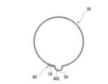
- FIG. 1 It is a partial sectional view of the shock absorber which concerns on embodiment of this invention. It is an enlarged view of the part A of FIG. It is a perspective view of the outer cover adopted for the shock absorber of FIG. It is a partial cross-sectional view along the line BB of FIG. It is sectional drawing which shows the other embodiment of the drainage groove of the outer cover adopted for the shock absorber of FIG. It is sectional drawing which shows still another embodiment of the drainage groove of the outer cover adopted for the shock absorber of FIG. It is sectional drawing which shows still another embodiment of the drainage groove of the outer cover adopted for the shock absorber of FIG. (A) is a cross-sectional view showing still another embodiment of the drainage groove of the outer cover adopted for the shock absorber of FIG.
- FIG. 10 is an enlarged view of part D in FIG. It is a perspective view which shows the other embodiment of the drainage hole of the outer cover adopted for the shock absorber of FIG.
- the shock absorber 1 according to the embodiment of the present invention is a damper for damping the rolling motion of a railway vehicle, and is installed sideways in a substantially horizontal direction between the vehicle body and the bogie or between the vehicle body and the vehicle body of the railway vehicle. It is a thing.
- the upper portion of the piston rod 15 will be referred to as the upper portion, and the lower portion will be referred to as the lower portion.
- cylindrical outer cylinders 3 are provided substantially concentrically on the outer circumference of the cylinder 2.
- An annular reservoir 4 is formed between the cylinder 2 and the outer cylinder 3. That is, the shock absorber 1 according to the present embodiment is formed in a double cylinder structure.
- One end openings of the cylinder 2 and the outer cylinder 3 are closed by the one end side bracket 7 and the base member 8. That is, one end opening of the cylinder 2 is liquid-tightly fitted in the base member 8.
- a disk-shaped plate portion 10 welded to one end of the outer cylinder 3 and one end-side bracket portion 11 projecting from the plate portion 10 to one end side are integrally connected. It is composed.
- One end opening of the outer cylinder 3 is closed by the plate portion 10 of the one end side bracket 7.
- One end side bracket portion 11 of the one end side bracket 7 is attached to the vehicle side.
- the base member 8 is arranged between the one end side bracket 7 and one end of the cylinder 2.
- the other end openings of the cylinder 2 and the outer cylinder 3 are closed by the rod guide 19 and the other end side plate 20.
- a piston 14 is slidably arranged in the cylinder 2 along the axial direction of the cylinder 2.
- the inside of the cylinder 2 is divided into two chambers, the cylinder chambers 2A and 2B, by the piston 14.
- One end of the piston rod 15 is connected to the piston 14 by a nut 16.
- the piston 14 is provided with a passage communicating between the cylinder chambers 2A and 2B.
- a check valve (damping valve) or the like is provided in the passage. The check valve imparts flow resistance to the hydraulic oil flowing through the passage as the piston rod 15 moves, and the check valve generates a damping force with respect to the stroke of the piston rod 15.
- the other end side of the piston rod 15 is slidably and liquid-tightly inserted into the rod guide 19 and the other end side plate 20 and extends to the outside of the cylinder 2 and the outer cylinder 3.
- the cylinder 2 is filled with hydraulic oil. Hydraulic oil and gas are sealed in the reservoir 4.
- the plate portion 10 of the base member 8 and the one end side bracket 7 is provided with a passage for communicating the cylinder chamber 2A and the reservoir 4.
- a check valve (damping valve) or the like is provided in the passage.
- the other end side bracket 23 is fixed to the other end of the piston rod 15.
- the other end side bracket 23 is provided with a disk-shaped head portion 24 located on one end side and connected to the other end (protruding end portion) of the piston rod 15 and projecting from the head portion 24 to the other end side.
- the other end side bracket portion 25 attached to the vehicle side is integrally connected to each other.
- the outer diameter of the head portion 24 is set to be slightly larger than the outer diameter of the outer cylinder 3.
- the rod guide 19 is formed in a cylindrical shape and is for slidably supporting the piston rod 15 protruding from the other end of the cylinder 2.
- the rod guide 19 is supported inside the other end side of the outer cylinder 3.
- the rod guide 19 is provided with a passage for communicating the cylinder chamber 2B and the reservoir 4.
- a check valve (damping valve) or the like may be provided in the passage.
- the other end side plate 20 having a threaded portion on the outer peripheral surface thereof is arranged.
- the other end side plate 20 is formed in an annular shape.
- the rod guide 19 is inside the other end portion of the outer cylinder 3. It is supported between the other end side plate 20 and the other end of the cylinder 2.
- An outer cover 30 is arranged on the outer circumference of the piston rod 15.
- the outer cover 30 is formed in a thin cylindrical shape.
- the outer cover 30 extends to substantially the center of the outer cylinder 3 in the axial direction so as to cover the entire outer circumference of the piston rod 15.
- the outer cover 30 is made of metal, and is formed by rolling a piece of substantially rectangular plate 31 into a cylindrical shape and welding both ends thereof.
- the outer cover 30 may be formed by welding a plurality of locations using a plurality of plate materials 31, 31.
- a bent portion 33 that bends a portion corresponding to the plate thickness outward and an extension portion 34 that continuously extends in the circumferential direction from the bent portion 33 are formed.
- the polymerization portion 36 is formed in the entire area along the axial direction of the outer cover 30.
- the space portion 37 is formed between the other end surface of the plate member 31 and the base portion of the bent portion 33 provided at one end of the plate member 31.
- the spots are spaced along the axial direction of the outer cover 30 with respect to the overlapping portion 36 formed by superimposing the inner peripheral surface of the extension portion 34 provided at one end of the plate material 31 on the outer peripheral surface of the other end of the plate material 31.
- the outer cover 30 is formed by joining by performing welding at a plurality of locations.
- the polymerization portion 36 may be joined by performing fillet welding between the outer peripheral surface of the other end of the plate material 31 and the tip surface of the extension portion 34 provided at one end of the plate material 31.
- a space portion 37 having a substantially rectangular cross section is formed between the other end surface of the plate material 31 and the base portion of the bent portion 33 provided at one end of the plate material 31 so as to be adjacent to the overlapping portion 36 of the plate material 31.
- the space 37 on the inner peripheral surface of the outer cover 30 functions as a drainage groove 40A having a substantially rectangular cross section.
- the drain groove 40A is located at the lowermost position when the shock absorber 1 is installed sideways.
- the drainage groove 40A is formed in the entire axial direction of the outer cover 30.
- a plurality of mounting holes 42, 42 are formed at one end of the outer cover 30 at intervals in the circumferential direction.
- the other end inner peripheral surface of the outer cover 30 is brought into contact with the outer peripheral surface of the head portion 24 of the other end side bracket 23, and the mounting bolts 43 and 43 are respectively mounted holes of the outer cover 30. It is screwed into the outer peripheral surface of the head portion 24 while being inserted into 42 and 42 (see FIG. 3), respectively. As a result, the other end of the outer cover 30 is fixed to the outer peripheral surface of the head portion 24 of the other end side bracket 23.
- an annular groove portion 45 is formed on the outer peripheral surface of the other end of the outer cylinder 3.
- a guide ring 47 is rotatably fitted between the inner peripheral surface of the outer cover 30 and the annular groove portion 45 of the outer cylinder 3.
- the guide ring 47 is formed in a C shape having a slit (not shown).
- the guide ring 47 is formed to have a substantially rectangular cross section.
- the guide ring 47 is made of synthetic resin.
- the guide ring 47 supports the outer cover 30 so as to leave a space between the outer cover 30 and the outer cylinder 3, and suppresses contact between the outer cover 30 and the outer cylinder 3. ..
- the guide ring 47 In the installed state (sideways installation) of the shock absorber 1, the guide ring 47 is arranged so that its slit (open side) faces downward.
- the slit of the guide ring 47 is positioned at an arbitrary position along the circumferential direction of the outer cylinder 3 depending on the behavior of the vehicle or the like. There is a risk of moving to. Then, referring to FIGS.
- a linear passage 49 extending in the entire axial direction of the outer cover 30 is formed between the outer peripheral surface of the guide ring 47 and the drainage groove 40A of the outer cover 30. Will be done.
- the drainage groove 40A (straight passage 49) provided in the outer cover 30 communicates the one end side and the other end side of the guide ring 47 in the axial direction in the outer cover 30.
- the guide ring 47 can communicate with one end side and the other end side in the axial direction regardless of the stroke length of the piston rod 15. it can.
- a tubular outer dust cover 52 is arranged between one end of the outer cover 30 and one end side of the outer cylinder 3.
- the outer dust cover 52 is formed in a bellows shape so as to be expandable and contractible in the axial direction.
- the outer dust cover 52 prevents dust from entering the outer cover 30 from between the other end side of the outer cover 30 and the outer cylinder 3 through the slit of the guide ring 47.
- the drain groove 40A (straight passage 49) provided in the outer cover 30 has the other end, that is, the fixed end of the outer cover 30 communicating with the outside.
- the shock absorber 1 according to the present embodiment includes the outer dust cover 52, it is not always necessary to provide the outer dust cover 52. When the outer dust cover 52 is not provided, the drainage grooves 40A provided in the outer cover 30 communicate with the outside at both ends in the axial direction.
- both ends of the plate member 31 are joined so as to overlap each other without providing a bent portion 33 at one end of the plate member 31.
- the outer cover 30 is configured. Then, a stepped portion 56 having a height corresponding to the thickness of the plate member 31 is formed at a position adjacent to the overlapping portion 54 in which both ends are overlapped.
- the stepped portion 56 provided on the outer cover 30 is located at the lowermost portion when the shock absorber 1 is installed sideways. As a result, the stepped portion 56 provided on the outer cover 30 functions as the drainage groove 40B.
- a U-shaped portion having a U-shaped cross section and protruding outward in the radial direction is provided at one end of the plate member 31.
- 58 and an extension 59 extending continuously from the U-shaped portion 58 in the circumferential direction are provided.
- a superposed portion 60 formed by superimposing the inner peripheral surface of the extension portion 59 provided at one end of the plate material 31 is formed on the outer peripheral surface of the other end of the plate material 31, and the superposed portion 60 is joined by welding to join the outer cover 30.
- the U-shaped portion 58 provided on the outer cover 30 is located at the lowermost portion when the shock absorber 1 is installed sideways. As a result, the U-shaped portion 58 provided on the outer cover 30 functions as the drainage groove 40C.
- a V-shaped portion having a V-shaped cross section and projecting outward in the radial direction is provided at one end of the plate member 31. 62 is provided. Then, the other end surface of the plate material 31 and one end surface of the plate material 31 are butted, and the butted portions are joined by welding to form the outer cover 30.
- the V-shaped portion 62 provided on the outer cover 30 is located at the lowermost portion when the shock absorber 1 is installed sideways. As a result, the V-shaped portion 62 provided on the outer cover 30 functions as the drainage groove 40D.
- a joint portion 64 formed by abutting both ends of the plate material 31 and joining them by welding is formed to form the outer cover 30.
- the weld bead generated in the joint portion 64 is bead-cut so as to be recessed from the inner peripheral surface of the outer cover 30 to form the recess 65.
- the recess 65 is formed in the entire area along the axial direction of the outer cover 30.
- the joint portion 64 and the recess 65 of the outer cover 30 are located at the lowermost portion when the shock absorber 1 is installed sideways. Then, the recess 65 provided in the joint portion 64 of the outer cover 30 functions as the drainage groove 40E.
- a plurality of recesses 67, 67 in which the entire wall portion is recessed are provided in the plate material 31 at intervals.
- the plate material 31 is rolled into a cylindrical shape, and both ends of the plate material 31 are abutted and joined by welding to form the outer cover 30.
- a plurality of recesses 67, 67 are formed on the inner peripheral surface of the outer cover 30 at intervals along the circumferential direction.
- the recesses 67 and 67 are formed in the entire area along the axial direction of the outer cover 30.
- any one of the plurality of recesses 67 and 67 provided in the outer cover 30 is located at the lowermost position when the shock absorber 1 is installed sideways.
- a recess 67 provided on the inner peripheral surface of the outer cover 30 and located at the lowermost portion functions as a drainage groove 40F.
- the mounting position along the circumferential direction of the outer cover 30 is not limited to one, and there are a plurality of recesses 67 corresponding to the number of recesses 67. It is possible to suppress erroneous assembly.
- the drain groove 40A communicates with the inner peripheral surface of the outer cover 30 between one end side and the other end side of the guide ring 47 in the axial direction and communicates with the outside of the outer cover 30.
- ⁇ 40F is formed, as shown in FIGS. 10 and 11, a plurality of outer covers 30 communicate with the outside of the outer cover 30 on both sides of the guide ring 47 on both the one end side and the other end side in the axial direction.
- the drain holes 70A and 70A may be provided through the holes 70A and 70A. In the case of this embodiment, the drain holes 70A and 70A are located at the lowermost part when the shock absorber 1 is installed sideways.
- the outer cover 30 is a joint portion extending in the axial direction (see, for example, reference numeral 64 in FIG. 8), which is formed by forming a single plate member 31 into a cylindrical shape so as to be rolled and joining the two ends by butt welding. Has. Then, a plurality of drain holes 70A and 70A may be formed at the joints thereof at intervals along the axial direction.
- the outer cover 30 forms a joint portion 72 extending in the axial direction, which is formed by forming a single plate member 31 into a cylindrical shape so as to be rolled and joining the two end portions abutting against each other.
- the joint portion 72 is configured by applying spot welds 73, 73 to both ends of the plate member 31 at a plurality of locations at intervals along the axial direction thereof.
- a plurality of gaps 74, 74 are formed in the joint portion 72 at intervals along the axial direction between the spot-welded portions 73, 73.
- the joint portion 72 and the gaps 74, 74 of the outer cover 30 are located at the lowermost portion when the shock absorber 1 is installed sideways. Then, the gaps 74 and 74 provided in the joint portion 72 of the outer cover 30 may function as drain holes 70B and 70B.
- the inner peripheral surface of the outer cover 30 is provided with water that communicates one end side and the other end side of the guide ring 47 in the axial direction in the outer cover 30.
- Drainage grooves 40A to 40F are provided, and the drainage grooves 40A to 40F communicate with the outside of the outer cover 30. Further, the drainage grooves 40A to 40F are located at the lowermost portion of the shock absorber 1 in the installed state.
- the guide ring 47 rotates along the annular groove portion 45 of the outer cylinder 3 due to the behavior of the vehicle or the like, and even if the slit is located on the upper side of the outer cylinder 3, it penetrates into the outer cover 30.
- the rainwater or the like can be easily discharged to the outside from the drainage slits 40A to 40F. As a result, corrosion of the rod guide 19 and the like can be suppressed, and reliability is improved.
- the guide ring 47 has rigidity to support the outer cover 30, it is possible to suppress the contact of the outer cover 30 with the outer cylinder 3, and as a result, damage to the outer peripheral surface of the outer cylinder 3 is caused. It can be suppressed, and the expansion / contraction operability of the shock absorber 1 can be ensured.
- the drainage grooves 40A to 40F provided on the inner peripheral surface of the outer cover 30 also function as air intake / exhaust holes in the outer cover 30 and the outer dust cover 52, so that the desired damping force characteristics of the shock absorber 1 are ensured. be able to.
- the drainage grooves 40A to 40F are always on one end side and the other end side in the axial direction of the guide ring 47 in the outer cover 30 regardless of the stroke length of the piston rod 15. It extends to the position where it communicates with. As a result, the drainage of rainwater or the like in the outer cover 30 can be easily performed regardless of the stroke length of the piston rod 15, and the desired damping force characteristic of the shock absorber 1 can be secured.
- the outer cover 30 is fixed to the head portion 24 of the other end side bracket 23 fixed to the piston rod 15, and the other end portion of the drainage grooves 40A to 40F is the outer cover 30. It communicates with the outside of.
- the drain groove 40A to The 40F can be communicated with the outside of the outer cover 30.
- the drainage groove 40B is composed of the stepped portion 56 adjacent to the overlapping portion 54 in which both ends of the plate material 31 overlap each other, so that the manufacturing cost of the outer cover 30 is reduced. be able to.
- the outer cover 30 is provided with drain holes 70A and 70A (70B, 70B) penetrating the outer cover 30 on both the one end side and the other end side in the axial direction of the guide ring 47, respectively. Be done. As a result, rainwater or the like that has entered the outer cover 30 can be easily discharged to the outside from the drain holes 70A, 70A (70B, 70B). Further, the drain holes 70A and 70A (70B, 70B) provided in the outer cover 30 also function as air intake / exhaust holes in the outer cover 30 and the outer dust cover 52, so that the desired damping force characteristics of the shock absorber 1 can be obtained. Can be secured.
- the shock absorber 1 has a configuration in which both ends of the plate member 31 are butted and joined by spot welding 73, 73 with gaps 74, 74 at a plurality of locations in the axial direction of the piston rod 15. Since the gaps 74 and 74 are the drain holes 70B and 70B, the manufacturing cost of the outer cover 30 can be reduced.
- the shock absorber 1 according to the present embodiment includes the outer dust cover 52 in addition to the guide ring 47, it is possible to suppress the intrusion of dust into the outer cover 30 from one end side.
- the shock absorber 1 according to the present embodiment even if the outer dust cover 52 is provided, the drainage grooves 40A to 40F or the drainage holes 70A, 70A (70B, 70B) provided in the outer cover 30 are external. Since it can communicate with the outer cover 30, it can be easily drained from the inside of the outer cover 30 to the outside.
- the shock absorber 1 It is possible to secure the desired damping force characteristics in.
- the present invention is not limited to the above-described embodiment, and includes various modifications.
- the above-described embodiment has been described in detail in order to explain the present invention in an easy-to-understand manner, and is not necessarily limited to the one including all the described configurations.
- it is possible to replace a part of the configuration of one embodiment with the configuration of another embodiment and it is also possible to add the configuration of another embodiment to the configuration of one embodiment.
- shock absorber 3 outer cylinder, 14 piston, 15 piston rod, 30 outer cover, 31 plate material, 47 guide ring, 40A-40F drain groove, 56 stepped part, 64 joint, 65 recess, 70A, 70B drain hole, 52 outer dust cover, 74 gap
Landscapes
- Engineering & Computer Science (AREA)
- General Engineering & Computer Science (AREA)
- Mechanical Engineering (AREA)
- Fluid-Damping Devices (AREA)
Priority Applications (3)
| Application Number | Priority Date | Filing Date | Title |
|---|---|---|---|
| JP2021563966A JP7220306B2 (ja) | 2019-12-11 | 2020-12-08 | 緩衝器 |
| CN202080085768.7A CN114829801A (zh) | 2019-12-11 | 2020-12-08 | 缓冲器 |
| EP20899320.4A EP4075013A4 (en) | 2019-12-11 | 2020-12-08 | SHOCK ABSORBER |
Applications Claiming Priority (2)
| Application Number | Priority Date | Filing Date | Title |
|---|---|---|---|
| JP2019223749 | 2019-12-11 | ||
| JP2019-223749 | 2019-12-11 |
Publications (1)
| Publication Number | Publication Date |
|---|---|
| WO2021117706A1 true WO2021117706A1 (ja) | 2021-06-17 |
Family
ID=76329837
Family Applications (1)
| Application Number | Title | Priority Date | Filing Date |
|---|---|---|---|
| PCT/JP2020/045627 Ceased WO2021117706A1 (ja) | 2019-12-11 | 2020-12-08 | 緩衝器 |
Country Status (4)
| Country | Link |
|---|---|
| EP (1) | EP4075013A4 (https=) |
| JP (1) | JP7220306B2 (https=) |
| CN (1) | CN114829801A (https=) |
| WO (1) | WO2021117706A1 (https=) |
Citations (8)
| Publication number | Priority date | Publication date | Assignee | Title |
|---|---|---|---|---|
| JPS5453258A (en) * | 1977-10-04 | 1979-04-26 | Matsushima Kogyo Kk | Thin film coil |
| JPS552896A (en) * | 1978-06-14 | 1980-01-10 | Gen Motors Corp | Telescopic type buffer and its manufacturing method |
| JPS57141247A (en) * | 1981-02-24 | 1982-09-01 | Ajinomoto Co Inc | Seasoning of snack foods |
| JPS6054851A (ja) * | 1983-07-29 | 1985-03-29 | オフイチネ メカニチエ ジオバンニ セルツテイ エス・ピ−・エ− | フレキソ印刷用原版保持ロ−ラ |
| JP2000211506A (ja) * | 1999-01-26 | 2000-08-02 | East Japan Railway Co | 鉄道車両用ダンパ装置 |
| DE102009051456A1 (de) * | 2009-10-30 | 2010-05-27 | Daimler Ag | Schutzanordnung |
| JP2014009804A (ja) | 2012-07-03 | 2014-01-20 | Kayaba Ind Co Ltd | 緩衝器 |
| WO2015121922A1 (ja) * | 2014-02-12 | 2015-08-20 | 日立オートモティブシステムズ株式会社 | シリンダ装置 |
Family Cites Families (8)
| Publication number | Priority date | Publication date | Assignee | Title |
|---|---|---|---|---|
| JPS5721834Y2 (https=) * | 1977-09-22 | 1982-05-12 | ||
| JPS6114752Y2 (https=) * | 1981-02-28 | 1986-05-08 | ||
| JPS6054851U (ja) * | 1983-09-21 | 1985-04-17 | 川崎重工業株式会社 | リヤサスペンシヨン |
| IT1228389B (it) * | 1988-01-21 | 1991-06-14 | Volkswagen Ag | Copertura di protezione per l'asta dello stantuffo di un ammortizzatore di vibrazioni idraulico per autoveicoli. |
| JPH09269030A (ja) * | 1996-03-29 | 1997-10-14 | Showa:Kk | 蓋体等の支持装置 |
| JPH10252801A (ja) * | 1997-01-07 | 1998-09-22 | Showa:Kk | ガススプリング |
| JP5460573B2 (ja) * | 2010-12-28 | 2014-04-02 | 本田技研工業株式会社 | 鞍乗型車両用油圧緩衝器 |
| DE102014205501B4 (de) * | 2014-03-25 | 2018-12-13 | Saf-Holland Gmbh | Schutzvorrichtung für einen Stoßdämpfer |
-
2020
- 2020-12-08 EP EP20899320.4A patent/EP4075013A4/en not_active Withdrawn
- 2020-12-08 CN CN202080085768.7A patent/CN114829801A/zh active Pending
- 2020-12-08 JP JP2021563966A patent/JP7220306B2/ja active Active
- 2020-12-08 WO PCT/JP2020/045627 patent/WO2021117706A1/ja not_active Ceased
Patent Citations (8)
| Publication number | Priority date | Publication date | Assignee | Title |
|---|---|---|---|---|
| JPS5453258A (en) * | 1977-10-04 | 1979-04-26 | Matsushima Kogyo Kk | Thin film coil |
| JPS552896A (en) * | 1978-06-14 | 1980-01-10 | Gen Motors Corp | Telescopic type buffer and its manufacturing method |
| JPS57141247A (en) * | 1981-02-24 | 1982-09-01 | Ajinomoto Co Inc | Seasoning of snack foods |
| JPS6054851A (ja) * | 1983-07-29 | 1985-03-29 | オフイチネ メカニチエ ジオバンニ セルツテイ エス・ピ−・エ− | フレキソ印刷用原版保持ロ−ラ |
| JP2000211506A (ja) * | 1999-01-26 | 2000-08-02 | East Japan Railway Co | 鉄道車両用ダンパ装置 |
| DE102009051456A1 (de) * | 2009-10-30 | 2010-05-27 | Daimler Ag | Schutzanordnung |
| JP2014009804A (ja) | 2012-07-03 | 2014-01-20 | Kayaba Ind Co Ltd | 緩衝器 |
| WO2015121922A1 (ja) * | 2014-02-12 | 2015-08-20 | 日立オートモティブシステムズ株式会社 | シリンダ装置 |
Non-Patent Citations (1)
| Title |
|---|
| See also references of EP4075013A4 |
Also Published As
| Publication number | Publication date |
|---|---|
| CN114829801A (zh) | 2022-07-29 |
| EP4075013A1 (en) | 2022-10-19 |
| JP7220306B2 (ja) | 2023-02-09 |
| EP4075013A4 (en) | 2022-12-28 |
| JPWO2021117706A1 (https=) | 2021-06-17 |
Similar Documents
| Publication | Publication Date | Title |
|---|---|---|
| RU2722581C1 (ru) | Гидро(пневмо)устройство и способ изготовления поршневого узла | |
| JP6420602B2 (ja) | 緩衝器 | |
| US20200256417A1 (en) | Valve and shock absorber | |
| JP2013242012A (ja) | 緩衝器 | |
| WO2014006985A1 (ja) | 緩衝器 | |
| US8561768B2 (en) | Vehicle damper and method | |
| WO2021117706A1 (ja) | 緩衝器 | |
| US10253840B2 (en) | Cylinder apparatus | |
| WO2014021103A1 (ja) | 緩衝器 | |
| JP6420601B2 (ja) | 緩衝器 | |
| JP6803271B2 (ja) | アキュムレータ | |
| KR101756419B1 (ko) | 쇽업소버의 더스트 씰 조립구조 | |
| US20250383005A1 (en) | Bumper cap and shock absorber | |
| JP5212822B2 (ja) | 液圧緩衝器 | |
| US10794447B2 (en) | Bump stopper and shock absorber | |
| JP6393565B2 (ja) | 緩衝器 | |
| US6186512B1 (en) | Piston ring | |
| US7559272B2 (en) | Cylinder apparatus | |
| JP6689332B2 (ja) | バンプストッパ、緩衝器およびバンプストッパの製造方法 | |
| JPWO2009116155A1 (ja) | ダンパ | |
| JP7483019B2 (ja) | 緩衝器 | |
| WO2016194548A1 (ja) | 緩衝器 | |
| JP2020112260A (ja) | 緩衝器 | |
| KR101227383B1 (ko) | 쇽업소버의 오일 씰 고정구조 | |
| KR20250140615A (ko) | 완충 장치, 현가 장치 |
Legal Events
| Date | Code | Title | Description |
|---|---|---|---|
| 121 | Ep: the epo has been informed by wipo that ep was designated in this application |
Ref document number: 20899320 Country of ref document: EP Kind code of ref document: A1 |
|
| ENP | Entry into the national phase |
Ref document number: 2021563966 Country of ref document: JP Kind code of ref document: A |
|
| NENP | Non-entry into the national phase |
Ref country code: DE |
|
| ENP | Entry into the national phase |
Ref document number: 2020899320 Country of ref document: EP Effective date: 20220711 |
|
| WWW | Wipo information: withdrawn in national office |
Ref document number: 2020899320 Country of ref document: EP |