WO2021117241A1 - ボタン用取付具 - Google Patents
ボタン用取付具 Download PDFInfo
- Publication number
- WO2021117241A1 WO2021117241A1 PCT/JP2019/049041 JP2019049041W WO2021117241A1 WO 2021117241 A1 WO2021117241 A1 WO 2021117241A1 JP 2019049041 W JP2019049041 W JP 2019049041W WO 2021117241 A1 WO2021117241 A1 WO 2021117241A1
- Authority
- WO
- WIPO (PCT)
- Prior art keywords
- cap
- flange portion
- button
- flange
- raised
- Prior art date
Links
Images


Classifications
-
- A—HUMAN NECESSITIES
- A44—HABERDASHERY; JEWELLERY
- A44B—BUTTONS, PINS, BUCKLES, SLIDE FASTENERS, OR THE LIKE
- A44B17/00—Press-button or snap fasteners
- A44B17/0041—Press-button fasteners consisting of two parts
-
- A—HUMAN NECESSITIES
- A44—HABERDASHERY; JEWELLERY
- A44B—BUTTONS, PINS, BUCKLES, SLIDE FASTENERS, OR THE LIKE
- A44B17/00—Press-button or snap fasteners
- A44B17/0005—Fastening of press-button fasteners
-
- A—HUMAN NECESSITIES
- A44—HABERDASHERY; JEWELLERY
- A44B—BUTTONS, PINS, BUCKLES, SLIDE FASTENERS, OR THE LIKE
- A44B17/00—Press-button or snap fasteners
- A44B17/0064—Details
- A44B17/007—Stud-member
Definitions
- the present invention relates to button attachments, in particular, button attachments for attaching snap buttons, tack buttons, buttons of the type that can be taken in and out of button holes, etc. to clothes or bag fabrics.
- the fixture main body includes a tubular portion and a flange portion extending radially outward from one end in the axial direction of the tubular portion.
- the fixture main body includes a tubular portion and a flange portion extending radially outward from one end in the axial direction of the tubular portion.
- the fixture body is connected to the cap by crimping the protruding end side portion of the annular protrusion with respect to the radial outer portion of the flange portion so as to plastically deform inward in the radial direction.
- the cylinder part of the attachment body of the button attachment is passed through from the back side to the front side of the cloth, and then the other end side in the axial direction of the cylinder part (the side opposite to the flange part). This is done by crimping the part against the button.
- the surface of the cap of the button attachment attached to clothes or the like together with the button is visible to the user on the back side of the clothes or the like. Therefore, a logo, characters, or the like may be attached to the surface of the cap.
- the connection of the cap to the attachment body may be weakened over time, and the cap may rotate with respect to the attachment body. In this case, the logo or characters on the surface of the cap are turned upside down, and the uniformity of the design is impaired. Further, the rotation of the cap with respect to the fixture body may separate the fixture body from the cap, or the button may easily come off from the fabric.
- an object of the present invention is to provide a button attachment that can eliminate or reduce the rotation of the cap with respect to the attachment body.
- the attachment is a button attachment including a metal attachment body and a synthetic resin cap to which the attachment body is connected.
- the tool body includes a tubular portion and a flange portion extending radially outward from one end in the axial direction of the tubular portion, and the flange portion includes a plurality of notches recessed inward in the radial direction from the peripheral edge of the flange portion.
- the cap is provided with a button attachment comprising a crimping portion of the flange portion that has been crimped to a radial outer portion including the plurality of notches.
- the flange portion of the fixture body is provided with a plurality of notches recessed inward in the radial direction from the peripheral edge thereof.
- the crimping portion of the cap is crimped to the radial outer portion of the flange portion including the plurality of notches, so that the crimping portion applies the radial outer portion of the flange portion to the back surface of the cap.
- the resin material of the crimping portion enters each notch so as to fill each notch. This makes it possible to eliminate or reduce the rotation of the cap with respect to the fixture body.
- examples of the metal forming the fixture body include aluminum, aluminum alloy, copper, copper alloy, nickel, nickel alloy, zinc, zinc alloy, iron, stainless steel and the like, but are limited thereto. It's not a thing.
- examples of the synthetic resin forming the cap include, but are not limited to, thermoplastic resins such as polyacetal, polyamide, polypropylene, and polybutylene terephthalate.
- the plurality of notches are formed at the predetermined angular intervals. For example, when there are three notches, the notches are formed at intervals of 120 degrees in the circumferential direction of the flange, and when there are five notches, the notches are formed at intervals of 72 degrees in the circumferential direction of the flange.
- each of the notches intersects the peripheral edge of the flange at an obtuse angle.
- Each notch is a portion obtained by removing a part of the flange so as to be recessed inward in the radial direction from the peripheral edge of the flange, and one notch intersects the peripheral edge of the flange at two points.
- the cap includes an annular ridge portion on the back surface of the fixture body facing the flange portion, which defines an accommodating portion for receiving the flange portion in the radial direction, and the crimping portion. Extends inward in the radial direction from the annular ridge, and the cap is located at the ridge-side end of the annular ridge on the opposite side of the crimping portion to the inside facing the radial outer portion of the flange. On the other hand, it includes an annular micro-recess that is recessed on the back surface side.
- the flange portion of the fixture body is arranged in the accommodating portion which is the space inside the annular ridge on the back surface of the cap in the radial direction.
- the crimping portion which was originally an extension portion on the raised side of the annular raised portion, is crimped to the radial outer portion of the flange portion.
- the radial outer portion of the flange portion is sandwiched between the back surface of the cap and the crimping portion, and is connected to the fixture body and the cap.
- the crimping part is crimped by heat crimping with heating, but by crimping the crimping part by cold working without heating, the manufacturing cost including electricity cost can be further reduced. ..
- cold working a sufficient amount of resin can be penetrated into the notch of the flange portion, and a minute recess is generated at the time of crimping. It can be seen that due to the presence of the minute recesses, the crimping portion firmly sandwiches the radial outer portion of the flange portion with the back surface of the cap.
- the cap includes a central raised portion that is raised in the center of the back surface.
- the central raised portion allows the base end side of the tubular portion of the fixture body to be supported when the tubular portion is crimped.
- the button is fixed to the fabric together with the button attachment by penetrating the cylinder of the attachment body through the fabric and then tightening the cylinder against the button.
- the central raised portion can support the base end side of the tubular portion, that is, the curved portion of the fixture body, which will be described later, thereby preventing buckling of the tubular portion.
- the cap when the cylinder is crimped when attaching the button to the fabric, the cap receives the crimping load, so dents remain on the surface of the cap opposite to the back surface, and the logo on the front surface is crushed. Defects can occur.
- the central portion of the cap is thickened by the central raised portion provided in the center of the back surface of the cap, and a part of the crimping load acting on the cap when the tubular portion is crimped is a thick central raised portion. By receiving it, it is possible to avoid or reduce the above-mentioned defects.
- the base end side of the tubular portion includes the vicinity of the tubular portion in the flange portion.
- the fixture body includes a curved portion that connects the tubular portion and the flange portion in a curved shape, and the central raised portion is raised to the end of the curved portion on the tubular portion side. ..
- the curved portion between the tubular portion and the flange portion is the portion where the crimping load is most applied to the fixture body when the tubular portion is crimped.
- the thickness of the central raised portion in the axial direction that is, the height from the back surface of the cap is extended to the end of the curved portion of the fixture body on the tubular portion side, so that the load is the largest when the tubular portion is crimped.
- the curved portion of the fixture body can be reliably supported by the central raised portion, which can prevent buckling of the tubular portion and the like.
- the flange portion of the fixture body is provided with a plurality of notches recessed inward in the radial direction from the peripheral edge thereof.
- the crimping portion of the cap is crimped to the radial outer portion of the flange portion including the plurality of notches, so that the crimping portion applies the radial outer portion of the flange portion to the back surface of the cap.
- the resin material of the crimping portion enters each notch so as to fill each notch. This makes it possible to eliminate or reduce the rotation of the cap with respect to the fixture body.
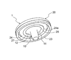
- FIG. 1 is a perspective view of a button attachment according to an embodiment of the present invention as viewed from the back side.
- FIG. 2 is a cross-sectional view of the button attachment of FIG.
- FIG. 3 is a bottom view of the button attachment of FIG. 1.
- FIG. 4 is an enlarged view of the box C portion of FIG.
- FIG. 5 is a cross-sectional view of the fixture body.
- FIG. 6 is a bottom view of the fixture body.
- FIG. 7 is an enlarged view of the box D portion of FIG.
- FIG. 8 is a cross-sectional view of the cap before assembly.
- FIG. 9 is a cross-sectional view showing a state in which the button is attached to the fabric by the button attachment.
- FIG. 10 is a cross-sectional view similar to FIG. 2 showing a modified example of the central raised portion.
- FIG. 1 is a perspective view of the button attachment 1 according to the embodiment of the present invention as viewed from the back side.
- FIG. 2 is a cross-sectional view of the button attachment 1.
- FIG. 3 is a bottom view of the button attachment 1.
- FIG. 4 is an enlarged view of the box C portion of FIG.
- the button attachment 1 is configured by integrally combining a metal attachment main body 10 and a synthetic resin cap 20.
- FIG. 5 is a cross-sectional view of the fixture main body 10.
- FIG. 6 is a bottom view of the fixture main body 10.
- FIG. 7 is an enlarged view of the box D portion of FIG.
- FIG. 8 is a cross-sectional view of the cap 20 before assembly.
- the vertical direction is based on the pages of FIGS. 2, 5, 8 and the like.
- the fixture main body 10 includes a tubular portion 11 and a flange portion 12 extending radially outward from the axial upper end (11a) of the tubular portion 11.
- the axial direction of the tubular portion 11 is along the vertical direction.
- the upper end (base end) of the tubular portion 11 in the axial direction refers to the position with the reference number 11a in FIG. 5, which is for convenience.
- the fixture main body 10 includes a curved portion 11c that connects the tubular portion 11 and the flange portion 12 in a curved shape.
- the upper end 11a of the tubular portion 11 is also the end of the curved portion 11c on the tubular portion 11 side.
- the curved portion 11c of the fixture main body 10 is a portion to which the crimping load is most applied when the tubular portion 11 is crimped when the button is attached using the fixture main body 10.
- the upper end 11a and the lower end 11b of the tubular portion 11 are open to the outside.
- the tubular portion 11 is a cylinder having a substantially constant inner and outer diameters.
- the inner and outer diameters of the curved portion 11c gradually expand outward and upward in the radial direction from the upper end 11a of the tubular portion 11 and are gently connected to the flange portion 12.
- the thickness of the tubular portion 11 along the radial direction becomes slightly thinner toward the lower end 11b.
- the radial outer half of the flange 12 descends slightly downward toward the radial outer end. Therefore, the cross sections of the curved portion 11c and the flange portion 12 are slightly curved so as to be slightly convex upward.
- the flange portion 12 of the fixture body 10 has a plurality of notches 13 recessed inward in the radial direction from the circular peripheral edge 12a which is the outer end in the radial direction.
- the flange portion 12 is provided with five notched portions 13 at intervals of 72 degrees.
- the number of notches 13 may be at least two and may be six or more.
- two notches 13 and 13 adjacent to each other in the circumferential direction are in contact with each other, and between the two notches 13 and 13. It is not preferable because a sharp portion may be formed on the surface. Therefore, it is preferable that the two notches 13, 13 adjacent to each other in the circumferential direction are provided at intervals without being in contact with each other.
- each cutout portion 13 has two cutout sides 13a and 13b and both cutout sides 13a and 13b that intersect the peripheral edge 12a at an obtuse angle ⁇ .
- the inside in the radial direction of the above is defined by a connecting side 13c that gently connects the inside in the radial direction with a rounded recess.
- the two notched sides 13a and 13b and the connecting side 13c are edges that define the notch portion 13 in the flange portion 12.
- the obtuse angle ⁇ is about 120 degrees, but the present invention is not limited to this.
- the cap 20 has a front surface 21 and a back surface 22.
- the surface 21 of the cap 20 becomes the surface 21 of the button attachment 1 after assembly (see FIG. 2 and the like).
- a central raised portion 25 that rises downward from the back surface 22 is provided at the center of the back surface 22.
- the lower end portion of the annular raised portion 24 is crimped to the flange portion 12 when combined with the fixture main body 10 to form a crimping portion 27 (see FIG.
- the lower end of the annular raised portion 24 before crimping protrudes below the lower end of the peripheral side portion 23.
- the lower end of the peripheral side portion 23 is located below the lower end (horizontal plane 25a) of the central raised portion 25.
- An accommodating portion 26, which is a space for arranging the flange portion 12 of the fixture main body 10, is defined on the back surface 22 of the cap 20 and inside the annular raised portion 24 in the radial direction.
- the inner diameter of the annular raised portion 24 is set to be the same as or slightly larger than the outer diameter of the flange portion 12.
- the outer diameter of the annular raised portion 24 gradually decreases from the upper end (base end) along the back surface 22 to the lower end. Therefore, the thickness of the annular raised portion 24 along the radial direction gradually decreases from the upper end to the lower end.
- the central raised portion 25 has a central horizontal plane 25a perpendicular to the axial direction, which is the lower end surface, and a curved portion supporting surface 25b that is gently connected to the back surface 22 while gradually increasing the outer diameter from the radial outer end of the horizontal plane 25a.
- the position of the horizontal plane 25a in the vertical direction is the same as the upper end 11a of the tubular portion 11 of the fixture main body 10.
- the curved portion support surface 25b is curved so as to substantially match the curved portion 11c of the fixture main body 10.
- the curved portion 11c can be reliably supported by the curved portion supporting surface 25b of the central raised portion 25 when the tubular portion 11 is crimped.
- the degree of curvature of the curved portion support surface 25c which will be described later and is inclined in a straight line, is smaller than that of the curved portion 11c of the fixture body 10.
- the R of the curved portion support surface 25c is infinite, and in the present specification, it is assumed that the R of the curved portion support surface 25c ⁇ the R of the curved portion 11c of the fixture main body 10.
- the flange portion 12 of the fixture body 10 is arranged in the accommodating portion 26 of the cap 20, and then the lower end portion of the annular raised portion 24 of the cap 20 is attached to the flange portion 12.
- the outer portion in the radial direction including the notch portion 13 is crimped.
- the lower end portion of the annular raised portion 24 is plastically deformed inward in the radial direction to become the crimping portion 27, and the outer end portion in the radial direction of the flange portion 12 is sandwiched between the back surface 22 of the cap 20.
- the resin of the crimping portion 27 enters each notch portion 13 so as to fill each notch portion 13 of the flange portion 12. This makes it possible to eliminate or reduce the situation in which the cap 20 rotates with respect to the fixture body 10 over time.
- FIG. 4 is an enlarged view of the enclosure C portion of FIG. 2, the lower end of the crimping portion 27 crimped to the flange portion 12 of the fixture main body 10 is attached to the lower end 24a of the annular raised portion 24.
- An annular micro-recess 28 that is slightly recessed upward is formed.
- the crimping portion 27 of the cap 20 is crimped to the radial outer portion of the flange portion 12 of the fixture body 10 by cold working without heating. As a result, the manufacturing cost could be reduced as compared with the heat crimping.
- the crimping portion 27 crimped by cold working firmly sandwiches the radial outer portion of the flange portion 12 with the back surface 22 of the cap 20.
- the axial position of the horizontal plane 25a, which is the lower end of the central raised portion 25, is substantially the same as that of the minute recess 28.
- FIG. 9 is a cross-sectional view showing a state in which a metal female snap button 30, which is an example of a button, is attached to the fabric f by the button attachment 1 described above.
- the female snap button 30 includes a receiving portion 30a which is a space for detachably receiving a male snap button (not shown), and a spring 31 which can elastically lock the male snap button received by the receiving portion 30a. Further, an opening 32 for receiving the tubular portion 11 of the button attachment 1 is provided at the bottom of the receiving portion 30a.
- the central raised portion 25 can support the curved portion 11c of the fixture main body 10 on the base end side of the tubular portion 11. As a result, buckling of the tubular portion 11 can be prevented. Further, as described above, by setting R (radius) of the curved portion support surface 25b of the central raised portion 25 ⁇ R of the curved portion 11c of the fixture main body 10, the crimping load is applied when the tubular portion 11 is crimped. The most such curved portion 11c can be reliably supported by the curved portion supporting surface 25b. As a result, not only buckling of the tubular portion 11 can be prevented, but also defects such as dents remaining on the surface 21 of the cap 20 and the logo of the surface 21 being crushed can be avoided or reduced.
- FIG. 10 is a cross-sectional view similar to FIG. 2 showing a modified example of the central raised portion 25 of the cap 20.
- the central raised portion 25 in FIG. 10 has a curved portion supporting surface 25c whose cross section is inclined linearly.
- the same reference number will be used and the description thereof will be omitted.
- the curved portion support surface 25c is connected to the horizontal back surface 22 of the cap 20 while gradually increasing the outer diameter from the radial outer end of the horizontal plane 25a. Even with such a curved portion supporting surface 25c having a linear cross section, the curved portion 11c of the fixture main body 10 can be supported when the tubular portion 11 is crimped, and buckling of the tubular portion 11 can be prevented. ..
Landscapes
- Slide Fasteners, Snap Fasteners, And Hook Fasteners (AREA)
Abstract
取付具本体に対するキャップの回動をなくすか低減することができるボタン用取付具を提供する。ボタン用取付具(1)は、金属製の取付具本体(10)と、前記取付具本体(10)が連結される合成樹脂製のキャップ(20)とからなる。前記取付具本体(10)は、筒部(11)と、前記筒部(11)の軸方向一端から半径方向外側に広がるフランジ部(12)とを備える。前記フランジ部(12)は、前記フランジ部(12)の周縁(12a)から半径方向内側に窪む複数の切欠部(13)を含む。前記キャップ(20)は、前記フランジ部(12)の、前記複数の切欠部(13)を含む半径方向外側部分に対して加締めた加締部(27)を含む。
Description
本発明はボタン用取付具、特に、スナップボタン、タックボタン、ボタン穴に出し入れするタイプのボタン等を衣服や鞄の生地に取り付けるためのボタン用取付具に関する。
ボタン用取付具として、金属製の取付具本体と合成樹脂製のキャップとを一体的に組み合わせてなるものが知られている。このようなボタン用取付具は、例えば、特許第3383900号公報、実開平2-43508号公報等に開示されている。取付具本体は、筒部と、筒部の軸方向一端から半径方向外側に広がるフランジ部とを備える。組立て前のキャップの裏面には環状の突起部があり、この環状の突起部の半径方向内側に取付具本体のフランジ部が配置される。次いで、環状の突起部の突端側部分を半径方向内側に塑性変形させるようにフランジ部の半径方向外側部分に対して加締めることにより、取付具本体がキャップに連結される。
衣服等の生地にボタンを取り付ける場合、ボタン用取付具における取付具本体の筒部を、生地の裏側から表側に貫通させた後、筒部の軸方向他端側(フランジ部とは反対側)部分をボタンに対して加締めることにより行われる。
衣服等にボタンと共に取り付けられたボタン用取付具は、衣服等の裏側においてキャップの表面がユーザから見える場合が多い。そのため、キャップの表面にはロゴや文字等が付される場合がある。しかしながら、従来のボタン用取付具では、経時的にキャップの取付具本体に対する連結が弱まり、キャップが取付具本体に対して回動するような事態が生じるおそれがあった。この場合、キャップの表面のロゴや文字が上下逆になったり、デザインの統一性が損なわれる。また、取付具本体に対するキャップの回動は、取付具本体とキャップを分離させたり、生地からボタンが外れやすくなるおそれがある。
上記のような点に鑑み、本発明は、取付具本体に対するキャップの回動をなくすか低減することができるボタン用取付具を提供することを目的とする。
上記課題を解決するため、本発明の一側面によれば、金属製の取付具本体と、前記取付具本体が連結される合成樹脂製のキャップとからなるボタン用取付具であって、前記取付具本体は、筒部と、前記筒部の軸方向一端から半径方向外側に広がるフランジ部とを備え、前記フランジ部は、前記フランジ部の周縁から半径方向内側に窪む複数の切欠部を含み、前記キャップは、前記フランジ部の、前記複数の切欠部を含む半径方向外側部分に対して加締めた加締部を含むことを特徴とするボタン用取付具が提供される。
本発明によれば、取付具本体のフランジ部に、その周縁から半径方向内側に窪む複数の切欠部を設けた。これにより、キャップの加締部を、フランジ部の、複数の切欠部を含む半径方向外側部分に対して加締めることで、加締部がフランジ部の半径方向外側部分をキャップの裏面に対して挟み付けると共に、加締部の樹脂材料が各切欠部を埋めるように各切欠部に入り込む。これにより、取付具本体に対するキャップの回動をなくすか低減することができる。
本発明において、取付具本体を形成する金属として、アルミニウム、アルミニウム合金、銅、銅合金、ニッケル、ニッケル合金、亜鉛、亜鉛合金、鉄、ステンレス鋼等を挙げることができるが、これらに限定されるものではない。また、キャップを形成する合成樹脂としては、ポリアセタール、ポリアミド、ポリプロピレン、ポリブチレンテレフタレート等の熱可塑性樹脂を挙げることができるが、これらに限定されるものではない。
本発明の一実施形態において、前記複数の切欠部は、前記所定角度間隔で形成される。例えば、切欠部が3つの場合、切欠部はフランジ部の周方向において120度間隔で形成され、切欠部が5つの場合、切欠部はフランジ部の周方向において72度間隔で形成される。
本発明の一実施形態において、各前記切欠部は、前記フランジ部の周縁に対して鈍角にて交差する。各切欠部は、フランジ部の周縁から半径方向内側に窪むようにフランジ部の一部を除去した部分であり、1つの切欠部はフランジの周縁に対して2箇所で交差する。この周縁に対して各切欠部が交差する2つの角をそれぞれ鈍角とすることにより、切欠部と周縁の角がキャップの対応部分を長期的に傷付けるようなことがなくなる。
本発明の一実施形態において、前記キャップは、前記取付具本体の前記フランジ部に対面する裏面において、前記フランジ部を受け入れる収容部を半径方向内側に規定する環状隆起部を含み、前記加締部は、前記環状隆起部から半径方向内側に延び、前記キャップは、前記加締部の、前記フランジ部の前記半径方向外側部分に対面する内側とは反対側において、前記環状隆起部の隆起側端に対して前記裏面側に窪む環状の微小凹部を含む。キャップに取付具本体を連結する際、まず、キャップの裏面における環状隆起部の半径方向内側の空間である収容部に取付具本体のフランジ部を配置する。次いで、元々は環状隆起部の隆起側延長部分であった加締部をフランジ部の半径方向外側部分に対して加締める。これにより、フランジ部の半径方向外側部分がキャップの裏面と加締部との間で挟み付けられ、取付具本体とキャップに連結される。一般に加締部の加締めは加熱を伴う熱加締により行われるが、加熱を伴わない冷間加工により加締部を加締めることにより、電気代等を含む製造コストをより削減することができる。このような冷間加工により、フランジ部の切欠部に対して十分な樹脂を入り込ませることができ、加締め時に微小凹部が生じる。この微小凹部の存在により、加締部がフランジ部の半径方向外側部分をキャップの裏面との間でしっかりと挟み付けていることが分かる。
本発明の一実施形態において、前記キャップは、前記裏面の中央において隆起する中央隆起部を含む。中央隆起部により、筒部の加締め時に取付具本体の筒部の基端側を支持させることができる。ボタン用取付具を用いてボタンを生地に取り付ける際、取付具本体の筒部を生地に貫通させ、次いでボタンに対して筒部を加締めることにより、ボタンがボタン用取付具と共に生地に固定される。この筒部の加締め時に、中央隆起部は、筒部の基端側すなわち取付具本体の後述する湾曲部を支持することができ、これにより、筒部の座屈を防ぐことができる。また、ボタンを生地に取り付ける際の筒部の加締め時において、キャップが加締めの荷重を受けるため、キャップの、裏面とは反対側の表面に打痕が残ったり、表面のロゴ等がつぶれる不良が生じ得る。本形態では、キャップの裏面の中央に設けた中央隆起部によりキャップの中央部が肉厚となり、筒部の加締め時にキャップに作用する加締めの荷重の一部を肉厚な中央隆起部で受けことで、上記した不良を回避したり、低減することが可能となる。なお、筒部の基端側にはフランジ部における筒部付近が含まれる。
本発明の一実施形態において、前記取付具本体は、筒部とフランジ部との間を湾曲状に繋ぐ湾曲部を含み、前記中央隆起部は前記湾曲部の前記筒部側の端まで隆起する。筒部とフランジ部との間の湾曲部は、筒部の加締め時に取付具本体において加締めの荷重が最もかかる部分である。本形態では、中央隆起部の軸方向における厚さ、すなわちキャップの裏面からの高さを、取付具本体の湾曲部の筒部側の端まで延ばすことにより、筒部の加締め時に荷重が最もかかる取付具本体の湾曲部を中央隆起部により確実に支持することができ、これにより筒部の座屈等を防ぐことができる。
本発明では、取付具本体のフランジ部に、その周縁から半径方向内側に窪む複数の切欠部を設けた。これにより、キャップの加締部を、フランジ部の、複数の切欠部を含む半径方向外側部分に対して加締めることで、加締部がフランジ部の半径方向外側部分をキャップの裏面に対して挟み付けると共に、加締部の樹脂材料が各切欠部を埋めるように各切欠部に入り込む。これにより、取付具本体に対するキャップの回動をなくすか低減することができる。
以下、本発明の実施形態を図面に基づいて説明するが、本発明はそのような実施形態に限定されるものではない。図1は、本発明の一実施形態に係るボタン用取付具1を裏側から見た斜視図である。図2は、ボタン用取付具1の断面図である。図3は、ボタン用取付具1の底面図である。図4は、図2の囲みC部分の拡大図である。ボタン用取付具1は、金属製の取付具本体10と合成樹脂製のキャップ20とを一体的に組み合わせて構成される。図5は、取付具本体10の断面図である。図6は、取付具本体10の底面図である。図7は、図6の囲みD部分の拡大図である。図8は、組立て前のキャップ20の断面図である。以下の説明において、上下方向は図2、5、8等の紙面に基づくものとする。
図5、図6等を参照して、取付具本体10は、筒部11と、筒部11の軸方向上端(11a)から半径方向外側に円板状に広がるフランジ部12とを備える。本明細書において、筒部11の軸方向は上下方向に沿う。また、本実施形態において、筒部11の軸方向における上端(基端)は、図5における参照番号11aを付した位置を言うものとするが、これは便宜的なものである。取付具本体10は、筒部11とフランジ部12との間を湾曲状に繋ぐ湾曲部11cを含む。筒部11の上端11aは、湾曲部11cの筒部11側の端でもある。取付具本体10の湾曲部11cは、ボタンを取付具本体10を用いて取り付ける際の筒部11の加締め時において加締めの荷重が最もかかる部分である。筒部11の上端11a及び下端11bは外部に開口する。本実施形態において、筒部11は、内外径がほぼ一定の円筒である。湾曲部11cの内外径は筒部11の上端11aから半径方向外側かつ上方へと次第に拡大しつつフランジ部12へとなだらかに繋がる。筒部11の半径方向に沿う厚さは下端11bへとわずかに薄くなる。フランジ部12の半径方向外側半部は、半径方向外側端へとわずかに下方に低下する。そのため、湾曲部11c及びフランジ部12の断面は上方にわずかに凸となるようにわずかに湾曲する。
図6を参照して、取付具本体10のフランジ部12は、半径方向外側端である円形の周縁12aから半径方向内側に窪む複数の切欠部13を有する。本実施形態において、フランジ部12には5つの切欠部13が72度間隔で設けられる。なお、切欠部13の数は、少なくとも2つあればよく、6つ以上であってもよい。ただし、フランジ部12の周縁12aに多数の切欠部13を連続的に設けるような態様は、周方向において隣り合う2つの切欠部13、13が接する形となり、この2つの切欠部13、13間に鋭角な部分が形成され得るため、好ましくない。そのため、周方向において隣り合う2つの切欠部13、13は互いに接することなく間隔をおいて設けられることが好ましい。
図6の囲みD部分の拡大図である図7を参照して、各切欠部13は、周縁12aに対して鈍角αにて交差する2つの切欠辺13a、13bと、両切欠辺13a、13bの半径方向内側を、半径方向内側に窪む丸みを付けてなだらかに連結する連結辺13cとにより規定される。2つの切欠辺13a、13b及び連結辺13cは、フランジ部12における切欠部13を規定する縁であるとも言える。本実施形態において、鈍角αは約120度であるが、これに限定されるものではない。切欠部13と周縁12aとの間に鋭角が生じないようにすることで、樹脂製のキャップ20に対して切欠部13が長期的に損傷を与えるようなことを防ぐことができる。
図8を参照して、キャップ20は表面21と裏面22とを有する。キャップ20の表面21は、組立て後のボタン用取付具1の表面21となる(図2等参照)。キャップ20の裏面22側には、半径方向外側端部にて下方に延びる周側部23と、周側部23の半径方向内側にて裏面22から下方に円環状に突出する環状隆起部24と、裏面22の中央において裏面22から下方に隆起する中央隆起部25とが設けられる。環状隆起部24の下端部は、後述するように取付具本体10との組合せ時にフランジ部12に対して加締められて加締部27(図2等参照)となる。加締め前の環状隆起部24の下端は周側部23の下端よりも下方に突出する。周側部23の下端は中央隆起部25の下端(水平面25a)よりも下方に位置する。キャップ20の裏面22上でかつ環状隆起部24の半径方向内側には、取付具本体10のフランジ部12を配置するための空間である収容部26が規定される。環状隆起部24の内径は、フランジ部12の外径と同じかわずかに大きくなるように設定される。環状隆起部24の外径は、裏面22に沿う上端(基端)から下端へと次第に縮小する。そのため、環状隆起部24の半径方向に沿う厚さは上端から下端へと次第に薄くなる。
中央隆起部25は、下端面である、軸方向に垂直な中央の水平面25aと、水平面25aの半径方向外側端から外径を次第に拡大しながら裏面22になだらかに繋がる湾曲部支持面25bとを有する。水平面25aの上下方向における位置は、取付具本体10の筒部11の上端11aと同じである。本実施形態において、湾曲部支持面25bは、取付具本体10の湾曲部11cにほぼ適合するように湾曲する。更に詳しくは、湾曲部支持面25bの湾曲の程度が取付具本体10の湾曲部11cよりも小さくなるように、湾曲部支持面25bのR(半径)≧取付具本体10の湾曲部11cのRとなるように設定される。これにより、筒部11の加締め時に湾曲部11cを中央隆起部25の湾曲部支持面25bで確実に支持することができる。なお、図10に示す後述する断面直線状に傾斜する湾曲部支持面25cも湾曲の程度が取付具本体10の湾曲部11cより小さいと言える。湾曲部支持面25cのRは無限大であるとも言え、本明細書において湾曲部支持面25cのR≧取付具本体10の湾曲部11cのRを満たすものとする。
取付具本体10をキャップ20に連結する場合、まず、取付具本体10のフランジ部12をキャップ20の収容部26に配置し、次いで、キャップ20の環状隆起部24の下端部を、フランジ部12の、切欠部13を含む半径方向外側部分に対して加締める。これにより、環状隆起部24の下端部が半径方向内側に塑性変形して加締部27となり、フランジ部12の半径方向外側端部をキャップ20の裏面22との間で挟み付ける。この際、加締部27の樹脂がフランジ部12の各切欠部13を埋めるように各切欠部13に入り込む。これにより、経時的にキャップ20が取付具本体10に対して回動するような事態をなくすか低減することができる。
図2の囲いC部分を拡大した図4を参照して、取付具本体10のフランジ部12に対して加締められた加締部27の下端には、環状隆起部24の下端24aに対して上方にわずかに窪む環状の微小凹部28が形成される。本実施形態では、取付具本体10のフランジ部12の半径方向外側部分に対するキャップ20の加締部27の加締め加工を、加熱を伴わない冷間加工で行った。これにより、熱加締に比べて製造コストを削減することができた。また、微小凹部28の存在により、冷間加工によって加締めた加締部27がフランジ部12の半径方向外側部分をキャップ20の裏面22との間でしっかりと挟み付けていることが分かる。図2を参照して、中央隆起部25の下端である水平面25aの軸方向における位置は、微小凹部28と実質的に同じとなる。
図9は、上述したボタン用取付具1によりボタンの一例である金属製の雌スナップボタン30を生地fに取り付けた状態を示す断面図である。雌スナップボタン30は、図示しない雄スナップボタンを着脱自在に受け入れる空間である受入部30aと、受入部30aに受け入れた雄スナップボタンを弾性的に係止可能なばね31とを備える。また、受入部30aの底部には、ボタン用取付具1の筒部11を受け入れるための開口32が設けられる。ボタン用取付具1を用いて雌スナップボタン30を生地fに取り付ける際、取付具本体10の筒部11を生地fに貫通させ、次いで雌スナップボタン30に対して筒部11を湾曲状に加締めることにより、雌スナップボタン30がボタン用取付具1と共に生地fに固定される。この筒部11の加締め時に、中央隆起部25は、筒部11基端側である取付具本体10の湾曲部11cを支持することができる。これにより、筒部11の座屈を防ぐことができる。また、上述したように中央隆起部25の湾曲部支持面25bのR(半径)≧取付具本体10の湾曲部11cのRに設定したことで、筒部11の加締め時に加締めの荷重が最もかかる湾曲部11cを湾曲部支持面25bで確実に支持することができる。これにより、筒部11の座屈を防ぐのみならず、キャップ20の表面21に打痕が残ったり、表面21のロゴ等がつぶれるといった不良を回避したり、低減することができる。
以上の実施形態では、キャップ20の中央隆起部25の湾曲部支持面25bが湾曲面である例を挙げたが、これに限定されるものではない。図10は、キャップ20の中央隆起部25の変形例を示す図2と同様の断面図である。図10の中央隆起部25は、断面が直線状に傾斜する湾曲部支持面25cを有する。図10において、湾曲部支持面25c以外の構成は既述した実施形態と同じであるため、同じ参照番号を用いて説明を省略する。湾曲部支持面25cは、水平面25aの半径方向外側端から外径を次第に拡大しながらキャップ20の水平な裏面22に繋がる。このような断面直線状の湾曲部支持面25cであっても、筒部11の加締め時に取付具本体10の湾曲部11cを支持することができ、筒部11の座屈を防ぐことができる。
1 ボタン用取付具
10 取付具本体
11 筒部
11a 筒部の上端(基端)
11c 湾曲部
12 フランジ部
12a フランジ部の周縁
13 切欠部
20 キャップ
22 キャップの裏面
24 環状隆起部
25 中央隆起部
25b、25c 湾曲部支持面
26 収容部
27 加締部
28 微小凹部
30 雌スナップボタン(ボタン)
f 生地
10 取付具本体
11 筒部
11a 筒部の上端(基端)
11c 湾曲部
12 フランジ部
12a フランジ部の周縁
13 切欠部
20 キャップ
22 キャップの裏面
24 環状隆起部
25 中央隆起部
25b、25c 湾曲部支持面
26 収容部
27 加締部
28 微小凹部
30 雌スナップボタン(ボタン)
f 生地
Claims (6)
- 金属製の取付具本体(10)と、前記取付具本体(10)が連結される合成樹脂製のキャップ(20)とからなるボタン用取付具(1)であって、
前記取付具本体(10)は、筒部(11)と、前記筒部(11)の軸方向一端から半径方向外側に広がるフランジ部(12)とを備え、
前記フランジ部(12)は、前記フランジ部(12)の周縁(12a)から半径方向内側に窪む複数の切欠部(13)を含み、
前記キャップ(20)は、前記フランジ部(12)の、前記複数の切欠部(13)を含む半径方向外側部分に対して加締めた加締部(27)を含むことを特徴とするボタン用取付具。 - 前記複数の切欠部(13)は、前記フランジ部(12)の周方向において所定角度間隔で形成される請求項1に記載のボタン用取付具。
- 各前記切欠部(13)は、前記フランジ部(12)の周縁(12a)に対して鈍角(α)にて交差する請求項1又は2に記載のボタン用取付具。
- 前記キャップ(20)は、前記取付具本体(10)の前記フランジ部(12)に対面する裏面(22)において、前記フランジ部(12)を受け入れる収容部(26)を半径方向内側に規定する環状隆起部(24)を含み、前記加締部(27)は、前記環状隆起部(24)から半径方向内側に延び、
前記キャップ(20)は、前記加締部(27)の、前記フランジ部(12)の前記半径方向外側部分に対面する内側とは反対側において、前記環状隆起部(24)の隆起側端に対して前記裏面(22)側に窪む環状の微小凹部(28)を含む請求項1~3のいずれか1項に記載のボタン用取付具。 - 前記キャップ(20)は、前記取付具本体(10)の前記フランジ部(12)に対面する裏面(22)の中央において隆起する中央隆起部(25)を含む請求項1~4のいずれか1項に記載のボタン用取付具。
- 前記取付具本体(10)は、前記筒部(11)と前記フランジ部(12)との間を湾曲状に繋ぐ湾曲部(11c)を含み、前記中央隆起部(25)は前記湾曲部(11c)の前記筒部(11)側の端(11a)まで隆起する請求項5に記載のボタン用取付具。
Priority Applications (5)
| Application Number | Priority Date | Filing Date | Title |
|---|---|---|---|
| US17/778,861 US11700919B2 (en) | 2019-12-13 | 2019-12-13 | Button attachment tool |
| JP2021563576A JP7198372B2 (ja) | 2019-12-13 | 2019-12-13 | ボタン用取付具 |
| DE112019007967.0T DE112019007967T5 (de) | 2019-12-13 | 2019-12-13 | Knopfbefestigungswerkzeug |
| PCT/JP2019/049041 WO2021117241A1 (ja) | 2019-12-13 | 2019-12-13 | ボタン用取付具 |
| CN201980101991.3A CN114641218B (zh) | 2019-12-13 | 2019-12-13 | 钮扣用安装件 |
Applications Claiming Priority (1)
| Application Number | Priority Date | Filing Date | Title |
|---|---|---|---|
| PCT/JP2019/049041 WO2021117241A1 (ja) | 2019-12-13 | 2019-12-13 | ボタン用取付具 |
Publications (1)
| Publication Number | Publication Date |
|---|---|
| WO2021117241A1 true WO2021117241A1 (ja) | 2021-06-17 |
Family
ID=76330134
Family Applications (1)
| Application Number | Title | Priority Date | Filing Date |
|---|---|---|---|
| PCT/JP2019/049041 WO2021117241A1 (ja) | 2019-12-13 | 2019-12-13 | ボタン用取付具 |
Country Status (5)
| Country | Link |
|---|---|
| US (1) | US11700919B2 (ja) |
| JP (1) | JP7198372B2 (ja) |
| CN (1) | CN114641218B (ja) |
| DE (1) | DE112019007967T5 (ja) |
| WO (1) | WO2021117241A1 (ja) |
Citations (4)
| Publication number | Priority date | Publication date | Assignee | Title |
|---|---|---|---|---|
| JPS553957A (en) * | 1978-06-26 | 1980-01-12 | Matsura Tokio | Wedge system saw frame clamping device in long saw machine |
| JPH0243508A (ja) * | 1988-08-03 | 1990-02-14 | Mitsubishi Cable Ind Ltd | イメージガイド装置 |
| DE19532339A1 (de) * | 1995-09-01 | 1997-03-06 | Stocko Fasteners Gmbh | Druckknopf-Verschlußteil |
| JPH10304908A (ja) * | 1997-05-08 | 1998-11-17 | Ykk Corp | ボタン等の取付用止め具 |
Family Cites Families (16)
| Publication number | Priority date | Publication date | Assignee | Title |
|---|---|---|---|---|
| FR2266469A1 (en) * | 1974-04-03 | 1975-10-31 | Schaeffer Homberg Gmbh | Decorative top press fastener - has push on lock consisting of barbed claws gripping inner top part projection |
| JPS5630251Y2 (ja) * | 1978-06-23 | 1981-07-18 | ||
| JPH0673482B2 (ja) * | 1985-06-19 | 1994-09-21 | 精 武田 | ホツク |
| JPH0243508U (ja) * | 1988-09-17 | 1990-03-26 | ||
| JP3106195B2 (ja) * | 1995-04-11 | 2000-11-06 | イバ工業株式会社 | 2部材の固定方法およびボタン本体に対する取付脚部材の固定構造 |
| JP3049560U (ja) * | 1997-06-20 | 1998-06-19 | 株式会社アイリス | 釦頭部取付け用止め具 |
| JP4221344B2 (ja) * | 2004-09-03 | 2009-02-12 | Ykk株式会社 | 止め具およびボタン |
| US7565721B2 (en) * | 2006-03-30 | 2009-07-28 | Ykk Corporation | Non-rotating sandwich button |
| CN102753051A (zh) * | 2009-12-14 | 2012-10-24 | Ykk株式会社 | 钮扣用固定件及钮扣结构体 |
| JP5615848B2 (ja) * | 2010-01-13 | 2014-10-29 | Ykk株式会社 | ボタン |
| CN104522943B (zh) * | 2014-12-25 | 2017-04-12 | 香港多耐福有限公司 | 一种按扣 |
| US10111497B2 (en) * | 2015-06-23 | 2018-10-30 | Ykk Corporation | Button back and button |
| WO2017042977A1 (ja) * | 2015-09-11 | 2017-03-16 | Ykk株式会社 | スナップボタン |
| US20190116941A1 (en) * | 2017-10-24 | 2019-04-25 | Charles A. Anderson | Cover For A Male Portion of a Snap Fastener and Method of Use |
| CN208080665U (zh) * | 2018-03-28 | 2018-11-13 | 东莞市伟廉金属制品有限公司 | 一种可防止面壳变形的按扣 |
| US20190328071A1 (en) * | 2018-04-30 | 2019-10-31 | VICIS, Inc. | Releasable impact mitigating fastener |
-
2019
- 2019-12-13 JP JP2021563576A patent/JP7198372B2/ja active Active
- 2019-12-13 CN CN201980101991.3A patent/CN114641218B/zh active Active
- 2019-12-13 DE DE112019007967.0T patent/DE112019007967T5/de active Pending
- 2019-12-13 WO PCT/JP2019/049041 patent/WO2021117241A1/ja active Application Filing
- 2019-12-13 US US17/778,861 patent/US11700919B2/en active Active
Patent Citations (4)
| Publication number | Priority date | Publication date | Assignee | Title |
|---|---|---|---|---|
| JPS553957A (en) * | 1978-06-26 | 1980-01-12 | Matsura Tokio | Wedge system saw frame clamping device in long saw machine |
| JPH0243508A (ja) * | 1988-08-03 | 1990-02-14 | Mitsubishi Cable Ind Ltd | イメージガイド装置 |
| DE19532339A1 (de) * | 1995-09-01 | 1997-03-06 | Stocko Fasteners Gmbh | Druckknopf-Verschlußteil |
| JPH10304908A (ja) * | 1997-05-08 | 1998-11-17 | Ykk Corp | ボタン等の取付用止め具 |
Also Published As
| Publication number | Publication date |
|---|---|
| US20220408885A1 (en) | 2022-12-29 |
| JPWO2021117241A1 (ja) | 2021-06-17 |
| CN114641218B (zh) | 2024-04-16 |
| CN114641218A (zh) | 2022-06-17 |
| DE112019007967T5 (de) | 2022-09-22 |
| JP7198372B2 (ja) | 2022-12-28 |
| US11700919B2 (en) | 2023-07-18 |
Similar Documents
| Publication | Publication Date | Title |
|---|---|---|
| WO2011040107A1 (ja) | ボタン及びボタン取付用上金型 | |
| JP6181766B2 (ja) | キャップ、ボタン類、及びボタン類形成方法 | |
| CN103291717B (zh) | 用于不漏流体地附接到片状金属部件的功能元件、构件组件和方法 | |
| US7703180B2 (en) | Pressure botton | |
| US10278457B2 (en) | Female snap button | |
| US4698881A (en) | Socket element assembly for snap fasteners | |
| EP3444485B1 (en) | Fastener and fastening arrangement | |
| WO2021117241A1 (ja) | ボタン用取付具 | |
| US11717061B2 (en) | Male member of snap fastener and snap fastener | |
| EP2084982A1 (en) | Female part of snap fastener | |
| US10111497B2 (en) | Button back and button | |
| EP0976340A2 (en) | Snap fastener capped rivet | |
| WO2008111622A1 (ja) | スナップファスナー部品 | |
| WO2010026872A1 (ja) | 雄型スナップ | |
| JP3143347B2 (ja) | スナップボタン | |
| JP2021154120A (ja) | 雄型スナップボタン | |
| TW201420032A (zh) | 公壓扣、壓扣、製品及具有公壓扣的薄片之製造方法 | |
| JP5955096B2 (ja) | スナップファスナー | |
| TWI457086B (zh) | Buttons and buttons for mounting | |
| JPWO2011040107A1 (ja) | ボタン及びボタン取付用上金型 | |
| JP2001347113A (ja) | ストレーナー |
Legal Events
| Date | Code | Title | Description |
|---|---|---|---|
| 121 | Ep: the epo has been informed by wipo that ep was designated in this application |
Ref document number: 19955694 Country of ref document: EP Kind code of ref document: A1 |
|
| ENP | Entry into the national phase |
Ref document number: 2021563576 Country of ref document: JP Kind code of ref document: A |
|
| 122 | Ep: pct application non-entry in european phase |
Ref document number: 19955694 Country of ref document: EP Kind code of ref document: A1 |