WO2021117241A1 - ボタン用取付具 - Google Patents
ボタン用取付具 Download PDFInfo
- Publication number
- WO2021117241A1 WO2021117241A1 PCT/JP2019/049041 JP2019049041W WO2021117241A1 WO 2021117241 A1 WO2021117241 A1 WO 2021117241A1 JP 2019049041 W JP2019049041 W JP 2019049041W WO 2021117241 A1 WO2021117241 A1 WO 2021117241A1
- Authority
- WO
- WIPO (PCT)
- Prior art keywords
- cap
- flange portion
- button
- flange
- raised
- Prior art date
- Legal status (The legal status is an assumption and is not a legal conclusion. Google has not performed a legal analysis and makes no representation as to the accuracy of the status listed.)
- Ceased
Links
Images



Classifications
-
- A—HUMAN NECESSITIES
- A44—HABERDASHERY; JEWELLERY
- A44B—BUTTONS, PINS, BUCKLES, SLIDE FASTENERS, OR THE LIKE
- A44B17/00—Press-button or snap fasteners
- A44B17/0041—Press-button fasteners consisting of two parts
-
- A—HUMAN NECESSITIES
- A44—HABERDASHERY; JEWELLERY
- A44B—BUTTONS, PINS, BUCKLES, SLIDE FASTENERS, OR THE LIKE
- A44B17/00—Press-button or snap fasteners
- A44B17/0005—Fastening of press-button fasteners
-
- A—HUMAN NECESSITIES
- A44—HABERDASHERY; JEWELLERY
- A44B—BUTTONS, PINS, BUCKLES, SLIDE FASTENERS, OR THE LIKE
- A44B17/00—Press-button or snap fasteners
- A44B17/0064—Details
- A44B17/007—Stud-member
Definitions
- the present invention relates to button attachments, in particular, button attachments for attaching snap buttons, tack buttons, buttons of the type that can be taken in and out of button holes, etc. to clothes or bag fabrics.
- the fixture main body includes a tubular portion and a flange portion extending radially outward from one end in the axial direction of the tubular portion.
- the fixture main body includes a tubular portion and a flange portion extending radially outward from one end in the axial direction of the tubular portion.
- the fixture body is connected to the cap by crimping the protruding end side portion of the annular protrusion with respect to the radial outer portion of the flange portion so as to plastically deform inward in the radial direction.
- the cylinder part of the attachment body of the button attachment is passed through from the back side to the front side of the cloth, and then the other end side in the axial direction of the cylinder part (the side opposite to the flange part). This is done by crimping the part against the button.
- the surface of the cap of the button attachment attached to clothes or the like together with the button is visible to the user on the back side of the clothes or the like. Therefore, a logo, characters, or the like may be attached to the surface of the cap.
- the connection of the cap to the attachment body may be weakened over time, and the cap may rotate with respect to the attachment body. In this case, the logo or characters on the surface of the cap are turned upside down, and the uniformity of the design is impaired. Further, the rotation of the cap with respect to the fixture body may separate the fixture body from the cap, or the button may easily come off from the fabric.
- an object of the present invention is to provide a button attachment that can eliminate or reduce the rotation of the cap with respect to the attachment body.
- the attachment is a button attachment including a metal attachment body and a synthetic resin cap to which the attachment body is connected.
- the tool body includes a tubular portion and a flange portion extending radially outward from one end in the axial direction of the tubular portion, and the flange portion includes a plurality of notches recessed inward in the radial direction from the peripheral edge of the flange portion.
- the cap is provided with a button attachment comprising a crimping portion of the flange portion that has been crimped to a radial outer portion including the plurality of notches.
- the flange portion of the fixture body is provided with a plurality of notches recessed inward in the radial direction from the peripheral edge thereof.
- the crimping portion of the cap is crimped to the radial outer portion of the flange portion including the plurality of notches, so that the crimping portion applies the radial outer portion of the flange portion to the back surface of the cap.
- the resin material of the crimping portion enters each notch so as to fill each notch. This makes it possible to eliminate or reduce the rotation of the cap with respect to the fixture body.
- examples of the metal forming the fixture body include aluminum, aluminum alloy, copper, copper alloy, nickel, nickel alloy, zinc, zinc alloy, iron, stainless steel and the like, but are limited thereto. It's not a thing.
- examples of the synthetic resin forming the cap include, but are not limited to, thermoplastic resins such as polyacetal, polyamide, polypropylene, and polybutylene terephthalate.
- the plurality of notches are formed at the predetermined angular intervals. For example, when there are three notches, the notches are formed at intervals of 120 degrees in the circumferential direction of the flange, and when there are five notches, the notches are formed at intervals of 72 degrees in the circumferential direction of the flange.
- each of the notches intersects the peripheral edge of the flange at an obtuse angle.
- Each notch is a portion obtained by removing a part of the flange so as to be recessed inward in the radial direction from the peripheral edge of the flange, and one notch intersects the peripheral edge of the flange at two points.
- the cap includes an annular ridge portion on the back surface of the fixture body facing the flange portion, which defines an accommodating portion for receiving the flange portion in the radial direction, and the crimping portion. Extends inward in the radial direction from the annular ridge, and the cap is located at the ridge-side end of the annular ridge on the opposite side of the crimping portion to the inside facing the radial outer portion of the flange. On the other hand, it includes an annular micro-recess that is recessed on the back surface side.
- the flange portion of the fixture body is arranged in the accommodating portion which is the space inside the annular ridge on the back surface of the cap in the radial direction.
- the crimping portion which was originally an extension portion on the raised side of the annular raised portion, is crimped to the radial outer portion of the flange portion.
- the radial outer portion of the flange portion is sandwiched between the back surface of the cap and the crimping portion, and is connected to the fixture body and the cap.
- the crimping part is crimped by heat crimping with heating, but by crimping the crimping part by cold working without heating, the manufacturing cost including electricity cost can be further reduced. ..
- cold working a sufficient amount of resin can be penetrated into the notch of the flange portion, and a minute recess is generated at the time of crimping. It can be seen that due to the presence of the minute recesses, the crimping portion firmly sandwiches the radial outer portion of the flange portion with the back surface of the cap.
- the cap includes a central raised portion that is raised in the center of the back surface.
- the central raised portion allows the base end side of the tubular portion of the fixture body to be supported when the tubular portion is crimped.
- the button is fixed to the fabric together with the button attachment by penetrating the cylinder of the attachment body through the fabric and then tightening the cylinder against the button.
- the central raised portion can support the base end side of the tubular portion, that is, the curved portion of the fixture body, which will be described later, thereby preventing buckling of the tubular portion.
- the cap when the cylinder is crimped when attaching the button to the fabric, the cap receives the crimping load, so dents remain on the surface of the cap opposite to the back surface, and the logo on the front surface is crushed. Defects can occur.
- the central portion of the cap is thickened by the central raised portion provided in the center of the back surface of the cap, and a part of the crimping load acting on the cap when the tubular portion is crimped is a thick central raised portion. By receiving it, it is possible to avoid or reduce the above-mentioned defects.
- the base end side of the tubular portion includes the vicinity of the tubular portion in the flange portion.
- the fixture body includes a curved portion that connects the tubular portion and the flange portion in a curved shape, and the central raised portion is raised to the end of the curved portion on the tubular portion side. ..
- the curved portion between the tubular portion and the flange portion is the portion where the crimping load is most applied to the fixture body when the tubular portion is crimped.
- the thickness of the central raised portion in the axial direction that is, the height from the back surface of the cap is extended to the end of the curved portion of the fixture body on the tubular portion side, so that the load is the largest when the tubular portion is crimped.
- the curved portion of the fixture body can be reliably supported by the central raised portion, which can prevent buckling of the tubular portion and the like.
- the flange portion of the fixture body is provided with a plurality of notches recessed inward in the radial direction from the peripheral edge thereof.
- the crimping portion of the cap is crimped to the radial outer portion of the flange portion including the plurality of notches, so that the crimping portion applies the radial outer portion of the flange portion to the back surface of the cap.
- the resin material of the crimping portion enters each notch so as to fill each notch. This makes it possible to eliminate or reduce the rotation of the cap with respect to the fixture body.
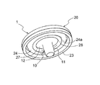
- FIG. 1 is a perspective view of a button attachment according to an embodiment of the present invention as viewed from the back side.
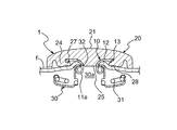
- FIG. 2 is a cross-sectional view of the button attachment of FIG.
- FIG. 3 is a bottom view of the button attachment of FIG. 1.
- FIG. 4 is an enlarged view of the box C portion of FIG.
- FIG. 5 is a cross-sectional view of the fixture body.
- FIG. 6 is a bottom view of the fixture body.
- FIG. 7 is an enlarged view of the box D portion of FIG.
- FIG. 8 is a cross-sectional view of the cap before assembly.
- FIG. 9 is a cross-sectional view showing a state in which the button is attached to the fabric by the button attachment.
- FIG. 10 is a cross-sectional view similar to FIG. 2 showing a modified example of the central raised portion.
- FIG. 1 is a perspective view of the button attachment 1 according to the embodiment of the present invention as viewed from the back side.
- FIG. 2 is a cross-sectional view of the button attachment 1.
- FIG. 3 is a bottom view of the button attachment 1.
- FIG. 4 is an enlarged view of the box C portion of FIG.
- the button attachment 1 is configured by integrally combining a metal attachment main body 10 and a synthetic resin cap 20.
- FIG. 5 is a cross-sectional view of the fixture main body 10.
- FIG. 6 is a bottom view of the fixture main body 10.
- FIG. 7 is an enlarged view of the box D portion of FIG.
- FIG. 8 is a cross-sectional view of the cap 20 before assembly.
- the vertical direction is based on the pages of FIGS. 2, 5, 8 and the like.
- the fixture main body 10 includes a tubular portion 11 and a flange portion 12 extending radially outward from the axial upper end (11a) of the tubular portion 11.
- the axial direction of the tubular portion 11 is along the vertical direction.
- the upper end (base end) of the tubular portion 11 in the axial direction refers to the position with the reference number 11a in FIG. 5, which is for convenience.
- the fixture main body 10 includes a curved portion 11c that connects the tubular portion 11 and the flange portion 12 in a curved shape.
- the upper end 11a of the tubular portion 11 is also the end of the curved portion 11c on the tubular portion 11 side.
- the curved portion 11c of the fixture main body 10 is a portion to which the crimping load is most applied when the tubular portion 11 is crimped when the button is attached using the fixture main body 10.
- the upper end 11a and the lower end 11b of the tubular portion 11 are open to the outside.
- the tubular portion 11 is a cylinder having a substantially constant inner and outer diameters.
- the inner and outer diameters of the curved portion 11c gradually expand outward and upward in the radial direction from the upper end 11a of the tubular portion 11 and are gently connected to the flange portion 12.
- the thickness of the tubular portion 11 along the radial direction becomes slightly thinner toward the lower end 11b.
- the radial outer half of the flange 12 descends slightly downward toward the radial outer end. Therefore, the cross sections of the curved portion 11c and the flange portion 12 are slightly curved so as to be slightly convex upward.
- the flange portion 12 of the fixture body 10 has a plurality of notches 13 recessed inward in the radial direction from the circular peripheral edge 12a which is the outer end in the radial direction.
- the flange portion 12 is provided with five notched portions 13 at intervals of 72 degrees.
- the number of notches 13 may be at least two and may be six or more.
- two notches 13 and 13 adjacent to each other in the circumferential direction are in contact with each other, and between the two notches 13 and 13. It is not preferable because a sharp portion may be formed on the surface. Therefore, it is preferable that the two notches 13, 13 adjacent to each other in the circumferential direction are provided at intervals without being in contact with each other.
- each cutout portion 13 has two cutout sides 13a and 13b and both cutout sides 13a and 13b that intersect the peripheral edge 12a at an obtuse angle ⁇ .
- the inside in the radial direction of the above is defined by a connecting side 13c that gently connects the inside in the radial direction with a rounded recess.
- the two notched sides 13a and 13b and the connecting side 13c are edges that define the notch portion 13 in the flange portion 12.
- the obtuse angle ⁇ is about 120 degrees, but the present invention is not limited to this.
- the cap 20 has a front surface 21 and a back surface 22.
- the surface 21 of the cap 20 becomes the surface 21 of the button attachment 1 after assembly (see FIG. 2 and the like).
- a central raised portion 25 that rises downward from the back surface 22 is provided at the center of the back surface 22.
- the lower end portion of the annular raised portion 24 is crimped to the flange portion 12 when combined with the fixture main body 10 to form a crimping portion 27 (see FIG.
- the lower end of the annular raised portion 24 before crimping protrudes below the lower end of the peripheral side portion 23.
- the lower end of the peripheral side portion 23 is located below the lower end (horizontal plane 25a) of the central raised portion 25.
- An accommodating portion 26, which is a space for arranging the flange portion 12 of the fixture main body 10, is defined on the back surface 22 of the cap 20 and inside the annular raised portion 24 in the radial direction.
- the inner diameter of the annular raised portion 24 is set to be the same as or slightly larger than the outer diameter of the flange portion 12.
- the outer diameter of the annular raised portion 24 gradually decreases from the upper end (base end) along the back surface 22 to the lower end. Therefore, the thickness of the annular raised portion 24 along the radial direction gradually decreases from the upper end to the lower end.
- the central raised portion 25 has a central horizontal plane 25a perpendicular to the axial direction, which is the lower end surface, and a curved portion supporting surface 25b that is gently connected to the back surface 22 while gradually increasing the outer diameter from the radial outer end of the horizontal plane 25a.
- the position of the horizontal plane 25a in the vertical direction is the same as the upper end 11a of the tubular portion 11 of the fixture main body 10.
- the curved portion support surface 25b is curved so as to substantially match the curved portion 11c of the fixture main body 10.
- the curved portion 11c can be reliably supported by the curved portion supporting surface 25b of the central raised portion 25 when the tubular portion 11 is crimped.
- the degree of curvature of the curved portion support surface 25c which will be described later and is inclined in a straight line, is smaller than that of the curved portion 11c of the fixture body 10.
- the R of the curved portion support surface 25c is infinite, and in the present specification, it is assumed that the R of the curved portion support surface 25c ⁇ the R of the curved portion 11c of the fixture main body 10.
- the flange portion 12 of the fixture body 10 is arranged in the accommodating portion 26 of the cap 20, and then the lower end portion of the annular raised portion 24 of the cap 20 is attached to the flange portion 12.
- the outer portion in the radial direction including the notch portion 13 is crimped.
- the lower end portion of the annular raised portion 24 is plastically deformed inward in the radial direction to become the crimping portion 27, and the outer end portion in the radial direction of the flange portion 12 is sandwiched between the back surface 22 of the cap 20.
- the resin of the crimping portion 27 enters each notch portion 13 so as to fill each notch portion 13 of the flange portion 12. This makes it possible to eliminate or reduce the situation in which the cap 20 rotates with respect to the fixture body 10 over time.
- FIG. 4 is an enlarged view of the enclosure C portion of FIG. 2, the lower end of the crimping portion 27 crimped to the flange portion 12 of the fixture main body 10 is attached to the lower end 24a of the annular raised portion 24.
- An annular micro-recess 28 that is slightly recessed upward is formed.
- the crimping portion 27 of the cap 20 is crimped to the radial outer portion of the flange portion 12 of the fixture body 10 by cold working without heating. As a result, the manufacturing cost could be reduced as compared with the heat crimping.
- the crimping portion 27 crimped by cold working firmly sandwiches the radial outer portion of the flange portion 12 with the back surface 22 of the cap 20.
- the axial position of the horizontal plane 25a, which is the lower end of the central raised portion 25, is substantially the same as that of the minute recess 28.
- FIG. 9 is a cross-sectional view showing a state in which a metal female snap button 30, which is an example of a button, is attached to the fabric f by the button attachment 1 described above.
- the female snap button 30 includes a receiving portion 30a which is a space for detachably receiving a male snap button (not shown), and a spring 31 which can elastically lock the male snap button received by the receiving portion 30a. Further, an opening 32 for receiving the tubular portion 11 of the button attachment 1 is provided at the bottom of the receiving portion 30a.
- the central raised portion 25 can support the curved portion 11c of the fixture main body 10 on the base end side of the tubular portion 11. As a result, buckling of the tubular portion 11 can be prevented. Further, as described above, by setting R (radius) of the curved portion support surface 25b of the central raised portion 25 ⁇ R of the curved portion 11c of the fixture main body 10, the crimping load is applied when the tubular portion 11 is crimped. The most such curved portion 11c can be reliably supported by the curved portion supporting surface 25b. As a result, not only buckling of the tubular portion 11 can be prevented, but also defects such as dents remaining on the surface 21 of the cap 20 and the logo of the surface 21 being crushed can be avoided or reduced.
- FIG. 10 is a cross-sectional view similar to FIG. 2 showing a modified example of the central raised portion 25 of the cap 20.
- the central raised portion 25 in FIG. 10 has a curved portion supporting surface 25c whose cross section is inclined linearly.
- the same reference number will be used and the description thereof will be omitted.
- the curved portion support surface 25c is connected to the horizontal back surface 22 of the cap 20 while gradually increasing the outer diameter from the radial outer end of the horizontal plane 25a. Even with such a curved portion supporting surface 25c having a linear cross section, the curved portion 11c of the fixture main body 10 can be supported when the tubular portion 11 is crimped, and buckling of the tubular portion 11 can be prevented. ..
Landscapes
- Slide Fasteners, Snap Fasteners, And Hook Fasteners (AREA)
Priority Applications (5)
| Application Number | Priority Date | Filing Date | Title |
|---|---|---|---|
| CN201980101991.3A CN114641218B (zh) | 2019-12-13 | 2019-12-13 | 钮扣用安装件 |
| JP2021563576A JP7198372B2 (ja) | 2019-12-13 | 2019-12-13 | ボタン用取付具 |
| US17/778,861 US11700919B2 (en) | 2019-12-13 | 2019-12-13 | Button attachment tool |
| PCT/JP2019/049041 WO2021117241A1 (ja) | 2019-12-13 | 2019-12-13 | ボタン用取付具 |
| DE112019007967.0T DE112019007967T5 (de) | 2019-12-13 | 2019-12-13 | Knopfbefestigungswerkzeug |
Applications Claiming Priority (1)
| Application Number | Priority Date | Filing Date | Title |
|---|---|---|---|
| PCT/JP2019/049041 WO2021117241A1 (ja) | 2019-12-13 | 2019-12-13 | ボタン用取付具 |
Publications (1)
| Publication Number | Publication Date |
|---|---|
| WO2021117241A1 true WO2021117241A1 (ja) | 2021-06-17 |
Family
ID=76330134
Family Applications (1)
| Application Number | Title | Priority Date | Filing Date |
|---|---|---|---|
| PCT/JP2019/049041 Ceased WO2021117241A1 (ja) | 2019-12-13 | 2019-12-13 | ボタン用取付具 |
Country Status (5)
| Country | Link |
|---|---|
| US (1) | US11700919B2 (https=) |
| JP (1) | JP7198372B2 (https=) |
| CN (1) | CN114641218B (https=) |
| DE (1) | DE112019007967T5 (https=) |
| WO (1) | WO2021117241A1 (https=) |
Citations (4)
| Publication number | Priority date | Publication date | Assignee | Title |
|---|---|---|---|---|
| JPS553957A (en) * | 1978-06-26 | 1980-01-12 | Matsura Tokio | Wedge system saw frame clamping device in long saw machine |
| JPH0243508A (ja) * | 1988-08-03 | 1990-02-14 | Mitsubishi Cable Ind Ltd | イメージガイド装置 |
| DE19532339A1 (de) * | 1995-09-01 | 1997-03-06 | Stocko Fasteners Gmbh | Druckknopf-Verschlußteil |
| JPH10304908A (ja) * | 1997-05-08 | 1998-11-17 | Ykk Corp | ボタン等の取付用止め具 |
Family Cites Families (16)
| Publication number | Priority date | Publication date | Assignee | Title |
|---|---|---|---|---|
| FR2266469A1 (en) * | 1974-04-03 | 1975-10-31 | Schaeffer Homberg Gmbh | Decorative top press fastener - has push on lock consisting of barbed claws gripping inner top part projection |
| JPS5630251Y2 (https=) * | 1978-06-23 | 1981-07-18 | ||
| JPH0673482B2 (ja) * | 1985-06-19 | 1994-09-21 | 精 武田 | ホツク |
| JPH0243508U (https=) * | 1988-09-17 | 1990-03-26 | ||
| JP3106195B2 (ja) * | 1995-04-11 | 2000-11-06 | イバ工業株式会社 | 2部材の固定方法およびボタン本体に対する取付脚部材の固定構造 |
| JP3049560U (ja) * | 1997-06-20 | 1998-06-19 | 株式会社アイリス | 釦頭部取付け用止め具 |
| JP4221344B2 (ja) * | 2004-09-03 | 2009-02-12 | Ykk株式会社 | 止め具およびボタン |
| US7565721B2 (en) * | 2006-03-30 | 2009-07-28 | Ykk Corporation | Non-rotating sandwich button |
| CN102753051A (zh) * | 2009-12-14 | 2012-10-24 | Ykk株式会社 | 钮扣用固定件及钮扣结构体 |
| EP2524612B1 (en) * | 2010-01-13 | 2019-04-10 | YKK Corporation | Member for attaching button and button |
| CN104522943B (zh) * | 2014-12-25 | 2017-04-12 | 香港多耐福有限公司 | 一种按扣 |
| WO2016207984A1 (ja) * | 2015-06-23 | 2016-12-29 | Ykk株式会社 | ボタンバック及びボタン |
| EP3348162B1 (en) * | 2015-09-11 | 2023-03-22 | YKK Corporation | Snap button |
| US20190116941A1 (en) * | 2017-10-24 | 2019-04-25 | Charles A. Anderson | Cover For A Male Portion of a Snap Fastener and Method of Use |
| CN208080665U (zh) * | 2018-03-28 | 2018-11-13 | 东莞市伟廉金属制品有限公司 | 一种可防止面壳变形的按扣 |
| US20190328071A1 (en) * | 2018-04-30 | 2019-10-31 | VICIS, Inc. | Releasable impact mitigating fastener |
-
2019
- 2019-12-13 DE DE112019007967.0T patent/DE112019007967T5/de active Pending
- 2019-12-13 WO PCT/JP2019/049041 patent/WO2021117241A1/ja not_active Ceased
- 2019-12-13 CN CN201980101991.3A patent/CN114641218B/zh active Active
- 2019-12-13 JP JP2021563576A patent/JP7198372B2/ja active Active
- 2019-12-13 US US17/778,861 patent/US11700919B2/en active Active
Patent Citations (4)
| Publication number | Priority date | Publication date | Assignee | Title |
|---|---|---|---|---|
| JPS553957A (en) * | 1978-06-26 | 1980-01-12 | Matsura Tokio | Wedge system saw frame clamping device in long saw machine |
| JPH0243508A (ja) * | 1988-08-03 | 1990-02-14 | Mitsubishi Cable Ind Ltd | イメージガイド装置 |
| DE19532339A1 (de) * | 1995-09-01 | 1997-03-06 | Stocko Fasteners Gmbh | Druckknopf-Verschlußteil |
| JPH10304908A (ja) * | 1997-05-08 | 1998-11-17 | Ykk Corp | ボタン等の取付用止め具 |
Also Published As
| Publication number | Publication date |
|---|---|
| JP7198372B2 (ja) | 2022-12-28 |
| US11700919B2 (en) | 2023-07-18 |
| US20220408885A1 (en) | 2022-12-29 |
| JPWO2021117241A1 (https=) | 2021-06-17 |
| DE112019007967T5 (de) | 2022-09-22 |
| CN114641218B (zh) | 2024-04-16 |
| CN114641218A (zh) | 2022-06-17 |
Similar Documents
| Publication | Publication Date | Title |
|---|---|---|
| JP5540003B2 (ja) | ボタン取付用上金型 | |
| JP6181766B2 (ja) | キャップ、ボタン類、及びボタン類形成方法 | |
| CN103291717B (zh) | 用于不漏流体地附接到片状金属部件的功能元件、构件组件和方法 | |
| US10278457B2 (en) | Female snap button | |
| CN102753051A (zh) | 钮扣用固定件及钮扣结构体 | |
| US11717061B2 (en) | Male member of snap fastener and snap fastener | |
| WO2021117241A1 (ja) | ボタン用取付具 | |
| CN101541201B (zh) | 按扣部件 | |
| WO2008038743A9 (ja) | スナップファスナーの雌部 | |
| TW201420032A (zh) | 公壓扣、壓扣、製品及具有公壓扣的薄片之製造方法 | |
| JP3143347B2 (ja) | スナップボタン | |
| JP5368575B2 (ja) | ボタン及びボタン取付用上金型 | |
| JP7651322B2 (ja) | 雄型スナップボタン | |
| US11653724B2 (en) | Snap button and female snap button | |
| TWI457086B (zh) | Buttons and buttons for mounting | |
| KR20190107110A (ko) | 암형 버튼, 및 암형 버튼과 수형 버튼의 조합품 | |
| JP2001347113A (ja) | ストレーナー |
Legal Events
| Date | Code | Title | Description |
|---|---|---|---|
| 121 | Ep: the epo has been informed by wipo that ep was designated in this application |
Ref document number: 19955694 Country of ref document: EP Kind code of ref document: A1 |
|
| ENP | Entry into the national phase |
Ref document number: 2021563576 Country of ref document: JP Kind code of ref document: A |
|
| 122 | Ep: pct application non-entry in european phase |
Ref document number: 19955694 Country of ref document: EP Kind code of ref document: A1 |