WO2021106555A1 - ソレノイド - Google Patents
ソレノイド Download PDFInfo
- Publication number
- WO2021106555A1 WO2021106555A1 PCT/JP2020/041940 JP2020041940W WO2021106555A1 WO 2021106555 A1 WO2021106555 A1 WO 2021106555A1 JP 2020041940 W JP2020041940 W JP 2020041940W WO 2021106555 A1 WO2021106555 A1 WO 2021106555A1
- Authority
- WO
- WIPO (PCT)
- Prior art keywords
- magnetic flux
- core
- solenoid
- respiratory
- yoke
- Prior art date
- Legal status (The legal status is an assumption and is not a legal conclusion. Google has not performed a legal analysis and makes no representation as to the accuracy of the status listed.)
- Ceased
Links
Images


Classifications
-
- H—ELECTRICITY
- H01—ELECTRIC ELEMENTS
- H01F—MAGNETS; INDUCTANCES; TRANSFORMERS; SELECTION OF MATERIALS FOR THEIR MAGNETIC PROPERTIES
- H01F7/00—Magnets
- H01F7/06—Electromagnets; Actuators including electromagnets
- H01F7/08—Electromagnets; Actuators including electromagnets with armatures
- H01F7/16—Rectilinearly-movable armatures
-
- F—MECHANICAL ENGINEERING; LIGHTING; HEATING; WEAPONS; BLASTING
- F16—ENGINEERING ELEMENTS AND UNITS; GENERAL MEASURES FOR PRODUCING AND MAINTAINING EFFECTIVE FUNCTIONING OF MACHINES OR INSTALLATIONS; THERMAL INSULATION IN GENERAL
- F16K—VALVES; TAPS; COCKS; ACTUATING-FLOATS; DEVICES FOR VENTING OR AERATING
- F16K31/00—Actuating devices; Operating means; Releasing devices
- F16K31/02—Actuating devices; Operating means; Releasing devices electric; magnetic
- F16K31/06—Actuating devices; Operating means; Releasing devices electric; magnetic using a magnet, e.g. diaphragm valves, cutting off by means of a liquid
- F16K31/0686—Braking, pressure equilibration, shock absorbing
- F16K31/0693—Pressure equilibration of the armature
-
- F—MECHANICAL ENGINEERING; LIGHTING; HEATING; WEAPONS; BLASTING
- F16—ENGINEERING ELEMENTS AND UNITS; GENERAL MEASURES FOR PRODUCING AND MAINTAINING EFFECTIVE FUNCTIONING OF MACHINES OR INSTALLATIONS; THERMAL INSULATION IN GENERAL
- F16K—VALVES; TAPS; COCKS; ACTUATING-FLOATS; DEVICES FOR VENTING OR AERATING
- F16K27/00—Construction of housing; Use of materials therefor
- F16K27/04—Construction of housing; Use of materials therefor of sliding valves
- F16K27/048—Electromagnetically actuated valves
-
- F—MECHANICAL ENGINEERING; LIGHTING; HEATING; WEAPONS; BLASTING
- F16—ENGINEERING ELEMENTS AND UNITS; GENERAL MEASURES FOR PRODUCING AND MAINTAINING EFFECTIVE FUNCTIONING OF MACHINES OR INSTALLATIONS; THERMAL INSULATION IN GENERAL
- F16K—VALVES; TAPS; COCKS; ACTUATING-FLOATS; DEVICES FOR VENTING OR AERATING
- F16K31/00—Actuating devices; Operating means; Releasing devices
- F16K31/02—Actuating devices; Operating means; Releasing devices electric; magnetic
- F16K31/06—Actuating devices; Operating means; Releasing devices electric; magnetic using a magnet, e.g. diaphragm valves, cutting off by means of a liquid
- F16K31/0603—Multiple-way valves
- F16K31/061—Sliding valves
- F16K31/0613—Sliding valves with cylindrical slides
-
- F—MECHANICAL ENGINEERING; LIGHTING; HEATING; WEAPONS; BLASTING
- F16—ENGINEERING ELEMENTS AND UNITS; GENERAL MEASURES FOR PRODUCING AND MAINTAINING EFFECTIVE FUNCTIONING OF MACHINES OR INSTALLATIONS; THERMAL INSULATION IN GENERAL
- F16K—VALVES; TAPS; COCKS; ACTUATING-FLOATS; DEVICES FOR VENTING OR AERATING
- F16K31/00—Actuating devices; Operating means; Releasing devices
- F16K31/02—Actuating devices; Operating means; Releasing devices electric; magnetic
- F16K31/06—Actuating devices; Operating means; Releasing devices electric; magnetic using a magnet, e.g. diaphragm valves, cutting off by means of a liquid
- F16K31/0675—Electromagnet aspects, e.g. electric supply therefor
-
- H—ELECTRICITY
- H01—ELECTRIC ELEMENTS
- H01F—MAGNETS; INDUCTANCES; TRANSFORMERS; SELECTION OF MATERIALS FOR THEIR MAGNETIC PROPERTIES
- H01F7/00—Magnets
- H01F7/06—Electromagnets; Actuators including electromagnets
- H01F7/08—Electromagnets; Actuators including electromagnets with armatures
- H01F7/081—Magnetic constructions
-
- H—ELECTRICITY
- H01—ELECTRIC ELEMENTS
- H01F—MAGNETS; INDUCTANCES; TRANSFORMERS; SELECTION OF MATERIALS FOR THEIR MAGNETIC PROPERTIES
- H01F7/00—Magnets
- H01F7/06—Electromagnets; Actuators including electromagnets
- H01F7/08—Electromagnets; Actuators including electromagnets with armatures
- H01F7/127—Assembling
-
- H—ELECTRICITY
- H01—ELECTRIC ELEMENTS
- H01F—MAGNETS; INDUCTANCES; TRANSFORMERS; SELECTION OF MATERIALS FOR THEIR MAGNETIC PROPERTIES
- H01F7/00—Magnets
- H01F7/06—Electromagnets; Actuators including electromagnets
- H01F7/08—Electromagnets; Actuators including electromagnets with armatures
- H01F7/16—Rectilinearly-movable armatures
- H01F7/1607—Armatures entering the winding
-
- H—ELECTRICITY
- H01—ELECTRIC ELEMENTS
- H01F—MAGNETS; INDUCTANCES; TRANSFORMERS; SELECTION OF MATERIALS FOR THEIR MAGNETIC PROPERTIES
- H01F7/00—Magnets
- H01F7/06—Electromagnets; Actuators including electromagnets
- H01F7/08—Electromagnets; Actuators including electromagnets with armatures
- H01F7/081—Magnetic constructions
- H01F2007/083—External yoke surrounding the coil bobbin, e.g. made of bent magnetic sheet
-
- H—ELECTRICITY
- H01—ELECTRIC ELEMENTS
- H01F—MAGNETS; INDUCTANCES; TRANSFORMERS; SELECTION OF MATERIALS FOR THEIR MAGNETIC PROPERTIES
- H01F7/00—Magnets
- H01F7/06—Electromagnets; Actuators including electromagnets
- H01F7/08—Electromagnets; Actuators including electromagnets with armatures
- H01F7/081—Magnetic constructions
- H01F2007/085—Yoke or polar piece between coil bobbin and armature having a gap, e.g. filled with nonmagnetic material
-
- H—ELECTRICITY
- H01—ELECTRIC ELEMENTS
- H01F—MAGNETS; INDUCTANCES; TRANSFORMERS; SELECTION OF MATERIALS FOR THEIR MAGNETIC PROPERTIES
- H01F7/00—Magnets
- H01F7/06—Electromagnets; Actuators including electromagnets
- H01F7/08—Electromagnets; Actuators including electromagnets with armatures
- H01F7/16—Rectilinearly-movable armatures
- H01F2007/1692—Electromagnets or actuators with two coils
Definitions
- This disclosure relates to solenoids.
- a solenoid in which a plunger slides inside a stator core inside a coil that generates a magnetic force by energization has been known.
- a magnetic ring core is arranged on the outer periphery of the stator core on the bottom side of the yoke.
- the magnetic circuit component such as the yoke and the stator core are magnetically coupled via the ring core, and the decrease in magnetic force due to the assembly gap between the magnetic circuit component and the stator core is suppressed.
- the inventors of the present application have configured the solenoid described in Patent Document 1 so that the ring core can move in the radial direction. Therefore, when the ring core is eccentrically assembled with respect to the sliding core, it is between the sliding core and the ring core. It was found that the size of the gap in the space may be biased in the radial direction. As a result, the inventor of the present application states that the distribution of the magnetic flux transmitted to the sliding core and the plunger through the ring core may be biased in the radial direction, and the attractive force in the radial direction may be generated as a side force. Thought. If the side force increases, the slidability of the plunger may deteriorate.
- the inventors of the present application integrate the ring core provided on the outer periphery of the stator core on the bottom side of the yoke with the sliding core, and use the stator core as the base portion that transfers the magnetic flux to the opening side of the yoke. I assumed a configuration to be separated.
- a solenoid has a coil portion that generates magnetic flux when energized, a cylindrical portion along the axial direction, and a bottom portion formed along a direction intersecting the axial direction, and a yoke that houses the coil portion.
- a columnar plunger that slides in the axial direction and a stator core that are arranged so as to face the tip surface of the plunger in the axial direction and magnetically attract the plunger by the magnetic flux generated by the coil portion.
- a sliding core having a first magnetic flux transfer portion formed from the opposite core end portions toward the outside in the radial direction and transferring magnetic flux between the yoke and the core portion, and the sliding core.
- a stator core having a magnetic flux passage suppressing portion that suppresses the passage of magnetic flux between the magnetic flux core and the magnetic attraction core, and a side opposite to the axial end portion of the magnetic attraction core that faces the tip surface.
- a second magnetic flux transfer portion which is arranged outside the radial direction of the end portion of the magnetic attraction core on the side and transfers magnetic flux between the magnetic attraction core and the cylindrical portion, is provided, and the cylindrical portion includes a second magnetic flux transfer portion.
- the first magnetic flux delivery portion is fitted in a gap.
- the sliding core is formed with a tubular core portion arranged radially outside the plunger and from the core end portion of the core portion toward the outside in the radial direction to transfer magnetic flux. Since the first magnetic flux delivery portion is provided, there is almost no radial gap between the core portion and the first magnetic flux delivery portion. Therefore, it is possible to prevent the core portion and the first magnetic flux delivery portion from being eccentric, so that the distribution of the magnetic flux transmitted from the first magnetic flux delivery portion to the plunger via the core portion due to such eccentricity is in the radial direction. It is possible to suppress the occurrence of bias. Therefore, it is possible to suppress an increase in side force due to a bias in the distribution of magnetic flux.
- the first magnetic flux delivery portion is gap-fitted in the cylindrical portion of the yoke, for example, a relatively large radial gap is formed between the cylindrical portion and the first magnetic flux delivery portion in order to secure a respiratory path.
- a relatively large radial gap is formed between the cylindrical portion and the first magnetic flux delivery portion in order to secure a respiratory path.
- This disclosure can also be realized in various forms.
- it can be realized in the form of a solenoid valve, a method for manufacturing a solenoid, or the like.
- FIG. 1 is a cross-sectional view showing a schematic configuration of a linear solenoid valve to which the solenoid of the first embodiment is applied.
- FIG. 2 is a cross-sectional view showing a detailed configuration of the solenoid.
- FIG. 3 is a cross-sectional view taken along the line III-III of FIG.
- FIG. 4 is a cross-sectional view taken along the line IV-IV of FIG.
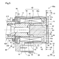
- FIG. 5 is a cross-sectional view showing a detailed configuration of the solenoid of the second embodiment.
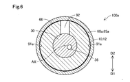
- FIG. 6 is a cross-sectional view taken along the line VI-VI of FIG. FIG.
- FIG. 7 is a cross-sectional view taken along the line VII-VII of FIG.
- FIG. 8 is a cross-sectional view showing a detailed configuration of the solenoid of the third embodiment.
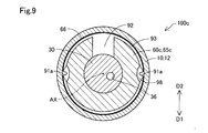
- FIG. 9 is a cross-sectional view showing a detailed configuration of the solenoid of the fourth embodiment.
- the solenoid 100 of the first embodiment shown in FIG. 1 is applied to the linear solenoid valve 300 and functions as an actuator for driving the spool valve 200.
- the linear solenoid valve 300 is used to control the hydraulic pressure of hydraulic oil supplied to an automatic transmission for vehicles (not shown), and is mounted on a valve body provided on the outer surface of a transmission case (not shown).
- the linear solenoid valve 300 of the present embodiment is used by being assembled to the valve body so that the position of the connector 26 described later in the circumferential direction is the ground direction D1.
- the "ground direction D1" means not only the vertical downward direction indicated by the arrow in FIG. 1, but also the vertical downward direction rather than the horizontal direction.
- the connector 26 is formed in the assembled state along the direction rotated at an angle of less than 90 ° with respect to the vertically downward direction.
- the ground direction D1 is preferably ⁇ 45 ° or more and + 45 ° or less with respect to the vertical downward direction.
- the position of the connector 26 in the circumferential direction is determined according to the mounting conditions of the linear solenoid valve 300. Note that FIG. 1 schematically shows a cross section of the linear solenoid valve 300 cut along the central axis AX and the vertical direction.
- the linear solenoid valve 300 includes a spool valve 200 and a solenoid 100 arranged side by side along the central axis AX. Note that FIGS. 1 and 2 show the solenoid 100 and the linear solenoid valve 300 in the non-energized state.
- the linear solenoid valve 300 of the present embodiment is a normally closed type, but may be a normally open type.
- the spool valve 200 shown in FIG. 1 adjusts the opening areas of a plurality of oil ports 214, which will be described later.
- the spool valve 200 includes a sleeve 210, a spool 220, a spring 230, and a spring load adjusting unit 240.
- the sleeve 210 has a substantially cylindrical external shape.
- the sleeve 210 is formed with an insertion hole 212 penetrating along the central axis AX and a plurality of oil ports 214 communicating with the insertion hole 212 and opening in the radial direction.
- a spool 220 is inserted into the insertion hole 212.
- the end of the insertion hole 212 on the solenoid 100 side is formed with an enlarged diameter and functions as an elastic member accommodating portion 218.
- the elastic member 420 which will be described later, is accommodated in the elastic member accommodating portion 218.
- the plurality of oil ports 214 are formed side by side along a direction parallel to the central axis AX (hereinafter, also referred to as "axial direction AD").
- the plurality of oil ports 214 are, for example, an input port that communicates with an oil pump (not shown) to receive an oil supply, an output port that communicates with a clutch piston (not shown) or the like to supply an oil pressure, and a spool 220 according to the output oil pressure. It functions as a feedback port that applies a load to the vehicle, a drain port that discharges hydraulic oil, and so on.
- the outer peripheral surface 211 of the end portion on the solenoid 100 side in the axial direction AD of the sleeve 210 is fastened to the inside of the base portion 80 described later.
- the radial direction means a direction orthogonal to the axial direction AD.
- the spool 220 has a substantially rod-like external shape in which a plurality of large diameter portions 222 and small diameter portions 224 are arranged side by side along the axial direction AD.
- the spool 220 slides along the axial direction AD inside the insertion hole 212, and opens a plurality of oil ports 214 according to the positions of the large diameter portion 222 and the small diameter portion 224 along the axial direction AD. adjust.
- a shaft 90 for transmitting the thrust of the solenoid 100 to the spool 220 is in contact with the end of the spool 220 on the solenoid 100 side.
- a spring 230 is arranged at the other end of the spool 220.
- the spring 230 is composed of a compression coil spring, and presses the spool 220 in the axial direction AD to urge the spool 220 toward the solenoid 100.
- the spring load adjusting unit 240 is arranged in contact with the spring 230, and the amount of screwing into the sleeve 210 is adjusted to adjust the spring load of the spring 230.
- the solenoid 100 shown in FIGS. 1 and 2 is energized and controlled by an electronic control device (not shown) to drive the spool valve 200.
- the solenoid 100 includes a yoke 10, a coil portion 20, a plunger 30, a stator core 40, and a base portion 80.
- the yoke 10 is formed of a magnetic metal and constitutes the outer shell of the solenoid 100.
- the yoke 10 has a bottomed tubular appearance shape, and accommodates the coil portion 20, the plunger 30, and the stator core 40.
- the yoke 10 has a cylindrical portion 12, a bottom portion 14, a thin-walled portion 17, and a notch portion 18.
- the cylindrical portion 12 has a substantially cylindrical external shape along the axial direction AD, and is arranged outside the coil portion 20 in the radial direction.
- a magnetic flux delivery portion 65 which will be described later, is gap-fitted in the cylindrical portion 12.
- the bottom portion 14 is connected to the end portion of the cylindrical portion 12 opposite to the spool valve 200 side and is formed perpendicular to the axial direction AD, and closes the end portion of the cylindrical portion 12.
- the bottom portion 14 is not limited to being perpendicular to the axial direction AD, but may be formed substantially perpendicular to the axial direction AD, or may be formed so as to intersect the axial direction AD according to the shape of the magnetic flux delivery portion 65 described later.
- the bottom portion 14 faces the proximal end surface 34 of the plunger 30, which will be described later.
- the space surrounded by the bottom portion 14, the stator core 40, and the shaft 90 is also referred to as a “plunger chamber 95”.
- the plunger 30 is housed in the plunger room 95.
- annular recess 94 centered on the central axis AX of the yoke 10 is formed on the inner surface of the bottom portion 14.
- the recess 94 is formed including an outer edge of the plunger 30 and a position facing the breathing hole 36 described later and the axial AD, and is configured so that the second breathing path 92 and the breathing hole 36 described later can communicate with each other. ing.
- the thin-walled portion 17 is formed to be thinner than the cylindrical portion 12 at the end of the cylindrical portion 12 on the spool valve 200 side.
- the thin portion 17 constitutes an opening of the yoke 10.
- the cutout portion 18 is formed by cutting out a part of the thin-walled portion 17 in the circumferential direction.
- the notch 18 of the present embodiment is formed so as to be in the ground direction D1 in the circumferential direction in a state where the solenoid 100 is assembled (hereinafter, also referred to as an “assembled state”).
- the notch 18 exposes the connector 26, which will be described later, from the yoke 10.
- the notch portion 18 functions as an inflow portion for flowing a fluid existing in the mounting environment of the solenoid 100 from the outside of the solenoid 100 into the inside of the solenoid 100.
- the fluid existing in the mounting environment of the solenoid 100 corresponds to a fluid such as hydraulic oil or air.
- the fluid that has flowed into the solenoid 100 through the notch 18 can also flow out to the outside of the solenoid 100 through the notch 18. That is, as the plunger 30 slides, the fluid can flow inside and outside the solenoid 100 through the notch 18.
- the coil portion 20 has a substantially cylindrical appearance shape, and is arranged inside the cylindrical portion 12 of the yoke 10 in the radial direction.
- the coil portion 20 has a coil 21 and a bobbin 22.
- the coil 21 is formed of a conducting wire having an insulating coating.
- the bobbin 22 is made of resin, and the coil 21 is wound around the bobbin 22.
- the bobbin 22 is connected to a connector 26 arranged on the outer peripheral portion of the yoke 10.
- the connector 26 is exposed radially outward from the yoke 10 via the notch 18.
- a connection terminal 24 to which the end of the coil 21 is connected is arranged.
- the connector 26 electrically connects the solenoid 100 and the electronic control device via a connection line (not shown).
- the coil portion 20 generates a magnetic force when energized, and a loop-shaped magnetic flux flows through the cylindrical portion 12 of the yoke 10, the bottom portion 14 of the yoke 10, the stator core 40, the plunger 30, and the base portion 80. (Hereinafter, also referred to as "magnetic circuit") is formed.
- magnetic circuit also referred to as "magnetic circuit"
- FIGS. 1 and 2 the coil portion 20 is not energized and the magnetic circuit is not formed.
- the magnetic circuit formed when the coil portion 20 is energized is executed.
- a part of C1 is schematically shown by a thick arrow in FIG.
- the outer diameter of the coil portion 20 is formed to be smaller than the inner diameter of the cylindrical portion 12 of the yoke 10. With such a configuration, a radial gap is formed over the entire circumference between the inner surface of the cylindrical portion 12 and the outer surface of the coil portion 20, and the first respiration of the magnetic flux delivery portion 65, which will be described later. It functions as a breathing passage 28 that communicates the road 91 with the outside of the solenoid 100.
- the breathing passage 28 communicates with the outside of the solenoid 100 through the notch 18 of the yoke 10 to circulate the fluid existing in the mounting environment of the solenoid 100.
- the notch 18 when the notch 18 is immersed in the hydraulic oil, the hydraulic oil as a fluid is circulated, and the notch 18 is located vertically above the storage level of the hydraulic oil. Circulates air as a fluid.
- the plunger 30 is housed in the plunger room 95.
- the plunger 30 has a substantially columnar appearance shape and is made of a magnetic metal.
- the plunger 30 slides on the inner peripheral surface of the core portion 61 of the stator core 40, which will be described later, in the axial direction AD.
- the shaft 90 described above is arranged in contact with the end surface (hereinafter, also referred to as “tip surface 32”) of the plunger 30 on the spool valve 200 side.
- tip surface 32 the end surface of the plunger 30 on the spool valve 200 side.
- the end surface of the plunger 30 opposite to the front end surface 32 faces the bottom portion 14 of the yoke 10.
- the plunger 30 is formed with a breathing hole 36 penetrating in the axial direction AD.
- the breathing hole 36 allows fluids located on the proximal end surface 34 side and the distal end surface 32 side of the plunger 30 to flow in the plunger chamber 95.
- the stator core 40 is made of a magnetic metal and is arranged between the coil portion 20 and the plunger 30.
- the stator core 40 is composed of a member in which a magnetic attraction core 50, a sliding core 60, and a magnetic flux passage suppressing portion 70 are integrated.
- the magnetic attraction core 50 is arranged so as to surround the shaft 90 in the circumferential direction.
- the magnetic attraction core 50 constitutes a portion of the stator core 40 on the spool valve 200 side, and magnetically attracts the plunger 30 by the magnetic force generated by the coil portion 20.
- a stopper 55 is arranged on the surface of the magnetic attraction core 50 facing the tip surface 32 of the plunger 30.
- the stopper 55 is made of a non-magnetic material and suppresses the direct contact between the plunger 30 and the magnetic attraction core 50, and prevents the plunger 30 from being separated from the magnetic attraction core 50 by magnetic attraction.
- the sliding core 60 constitutes a portion of the stator core 40 on the bottom 14 side, and is arranged on the outer side in the radial direction of the plunger 30.
- the sliding core 60 has a core portion 61 and a magnetic flux delivery portion 65.
- the core portion 61 has a substantially cylindrical appearance shape, and is arranged between the coil portion 20 and the plunger 30 in the radial direction.
- the core portion 61 guides the movement of the plunger 30 along the axial AD.
- the plunger 30 slides directly on the inner peripheral surface of the core portion 61.
- the end of the sliding core 60 which is opposite to the magnetic attraction core 50 side (hereinafter, also referred to as “core end 62”), faces the bottom 14 and is in contact with the bottom 14.
- FIG. 2 shows a cross section including the second respiratory passage 92 formed in the vertical direction D2, which will be described later, and the sliding core 60 and the bottom portion 14 are not in contact with each other in the second respiratory passage 92.
- the magnetic flux delivery portion 65 is formed from the core end portion 62 toward the outer side in the radial direction over the entire circumference of the core end portion 62. Therefore, the magnetic flux delivery portion 65 is located between the bobbin 22 and the bottom portion 14 of the yoke 10 in the axial direction AD.
- the magnetic flux transfer unit 65 transfers the magnetic flux between the yoke 10 and the plunger 30 via the core unit 61. More specifically, the magnetic flux transfer portion 65 of the present embodiment transfers the magnetic flux between the bottom portion 14 of the yoke 10 and the plunger 30.
- the magnetic flux delivery portion 65 of this embodiment is integrally formed with the core portion 61 by forging.
- the magnetic flux delivery portion 65 and the core portion 61 may be integrated after being formed as separate bodies from each other.
- the core portion 61 may be press-fitted into the through hole of the magnetic flux delivery portion 65 formed in a ring shape, or may be fixed by welding or the like after the core portion 61 is inserted.
- the magnetic flux transfer portion 65 is gap-fitted into the cylindrical portion 12 of the yoke 10. In other words, the clearance between the outer diameter of the magnetic flux delivery portion 65 and the inner diameter of the cylindrical portion 12 is formed so that a gap can be fitted.
- a first respiratory path 91 is formed on the outer peripheral surface 66 of the magnetic flux delivery portion 65 along the axial direction AD.
- the first respiratory tract 91 communicates with the respiratory passage 28.
- the number of the first respiratory passages 91 formed on the outer peripheral surface 66 of the magnetic flux delivery portion 65 is one.
- the first respiratory tract 91 has a linear groove shape, and is formed so as to be located in the vertical direction D2 in a state where the solenoid 100 is assembled.
- the "heavenly direction D2" is not limited to the vertically upward direction indicated by the arrow in FIG. 3, but means a direction on the vertically upward direction side rather than the horizontal direction.
- the first respiratory tract 91 is formed along the direction rotated at an angle of less than 90 ° with respect to the vertically upward direction in the assembled state.
- the top direction D2 is preferably ⁇ 45 ° or more and + 45 ° or less with respect to the vertically upward direction.
- the magnetic flux delivery portion 65 is formed with a first facing surface 68 facing the bottom portion 14 of the yoke 10.
- a second respiratory path 92 is formed on the first facing surface 68 of the magnetic flux delivery portion 65 along the radial direction.
- the second respiratory tract 92 is formed to communicate the first respiratory tract 91 with the plunger chamber 95.
- the second respiratory tract 92 is formed as a groove whose depth direction is the axial direction AD on the first facing surface 68.
- the second respiratory tract 92 is formed so that the position in the circumferential direction is the same as that of the first respiratory tract 91.
- the second respiratory tract 92 is formed in a range that is in the vertical direction D2 when the solenoid 100 is assembled. Further, in the present embodiment, the second respiratory tract 92 has a linear groove shape along the vertical direction.
- the portion of the bottom portion 14 of the yoke 10 facing the first facing surface 68 is also referred to as a “second facing surface 19” as shown in FIG.
- the magnetic flux passage suppressing portion 70 shown in FIG. 2 is formed between the magnetic attraction core 50 and the core portion 61 in the axial direction AD.
- the magnetic flux passage suppressing unit 70 suppresses the flow of magnetic flux directly between the core unit 61 and the magnetic attraction core 50.
- the magnetic flux passage suppressing portion 70 of the present embodiment is configured such that the magnetic flux passage suppressing portion 70 is formed so that the thickness of the stator core 40 in the radial direction is thin, so that the magnetic resistance is larger than that of the magnetic attraction core 50 and the core portion 61.
- the magnetic flux passage suppressing unit 70 may have a configuration in which the magnetic attraction core 50 and the sliding core 60, which are formed as separate bodies from each other, are physically connected by a non-magnetic material.
- the stator core 40 is urged toward the bottom 14 side in the axial direction AD by the elastic member 420 accommodated in the elastic member accommodating portion 218 formed in the sleeve 210 of the spool valve 200.
- the elastic member 420 is arranged in contact with the end face of the magnetic attraction core 50 in the axial direction AD and on the side opposite to the plunger 30 side.
- the elastic member 420 is composed of a compression coil spring having a substantially cylindrical appearance shape.
- a spool 220 is inserted inside the elastic member 420 in the radial direction.
- the stator core 40 is urged in the axial direction AD toward the bottom 14 side of the yoke 10 by the elastic member 420, the magnetic flux delivery portion 65 is pressed against the bottom 14 and from the bottom 14 of the yoke 10 to the magnetic flux delivery portion 65. The loss of the transmitted magnetic flux is suppressed.
- the base portion 80 is an end portion of the magnetic attraction core 50 of the stator core 40 in the axial direction AD and opposite to the side facing the tip surface 32 (hereinafter, also referred to as “magnetic attraction core end portion 52”). It is arranged on the outer side in the radial direction of.
- the base portion 80 has a substantially tubular appearance shape and is made of a magnetic metal.
- the base portion 80 transfers magnetic flux between the magnetic attraction core 50 of the stator core 40 and the cylindrical portion 12 of the yoke 10.
- the base portion 80 has a first cylinder portion 86 and a collar portion 87.
- the outer peripheral surface 211 of the sleeve 210 is press-fitted into the first tubular portion 86 and fastened to the outer peripheral surface 211.
- the collar portion 87 is connected to the first cylinder portion 86 in the axial direction AD, and has an outer diameter larger than the outer diameter of the first cylinder portion 86.
- the flange portion 87 is arranged outside the magnetic attraction core end portion 52 of the magnetic attraction core 50 in the radial direction, and is in contact with the inner peripheral surface of the cylindrical portion 12 of the yoke 10.
- the inner diameter of the first cylinder portion 86 is larger than the inner diameter of the flange portion 87, and the inner peripheral surface 81 of the first cylinder portion 86 and the inner peripheral surface 82 of the collar portion 87 are substantially parallel in the radial direction. It is connected by a connecting surface 83.
- the connecting surface 83 is in contact with the end surface of the sleeve 210 in the axial direction AD.
- the yoke 10, the plunger 30, the stator core 40, and the base portion 80 are each made of iron, but are not limited to iron and are made of any magnetic material such as nickel or cobalt. May be good.
- the outer peripheral surface of the plunger 30 is plated. By such a plating treatment, the surface hardness of the plunger 30 can be increased, and deterioration of slidability can be suppressed.
- the yoke 10 is formed into a cup shape by press molding, and the stator core 40 is formed by forging, but each may be formed by any molding method.
- the yoke 10 may be integrated by caulking or press-fitting after the cylindrical portion 12 and the bottom portion 14 are formed separately from each other.
- the solenoid 100 of the present embodiment is assembled by inserting the members housed inside the yoke 10 in order from the opening formed by the thin portion 17 of the yoke 10. More specifically, first, the stator core 40 in which the plunger 30 is housed inside the core portion 61 in the radial direction is inserted into the inside of the yoke 10 through the opening. At this time, the magnetic flux delivery portion 65 is gap-fitted into the cylindrical portion 12 of the yoke 10. Therefore, it is possible to prevent the central axis AX of the stator core 40 and the central axis AX of the yoke 10 from being displaced during assembly.
- the coil portion 20 is inserted, and the base portion 80 is gap-fitted with the magnetic attraction core end portion 52 on the inner peripheral surface 82 of the flange portion 87.
- the thin-walled portion 17 in contact with the outer peripheral surface 84 of the flange portion 87 is caulked and fixed to the base portion 80, so that the assembly of the solenoid 100 is completed.
- the cylindrical portion 12 of the yoke 10 and the base portion 80 may be fixed by any method such as welding.
- the base portion 80 is not limited to the gap fitting, and may be fitted with the magnetic attraction core end portion 52 by providing a slight gap in the radial direction.
- FIGS. 1 and 2 show a state in which the plunger 30 is farthest from the magnetic attraction core 50 without energizing the coil 21.
- the magnetic circuit C1 is formed inside the solenoid 100.
- the plunger 30 is attracted to the magnetic attraction core 50 side by the formation of the magnetic circuit C1 and slides on the inner peripheral surface of the core portion 61 in the axial direction AD.
- the current flowing through the coil portion 20 increases, the magnetic flux density of the magnetic circuit C1 increases, and the stroke amount of the plunger 30 increases.
- the opening area of the oil port 214 is adjusted, and the oil pressure proportional to the current value flowing through the coil 21 is output.
- the fluid such as hydraulic oil existing in the mounting environment of the solenoid 100 is charged with the stroke of the plunger 30, the notch 18, the breathing passage 28, the first breathing passage 91, the second breathing passage 92, the recess 94, and the breathing hole 36. To distribute. Since the plunger chamber 95 and the outside of the solenoid 100 are communicated with each other in this way, the pressure fluctuation of the plunger chamber 95 is suppressed as the plunger 30 slides, and the smooth sliding of the plunger 30 is hindered. Is suppressed.
- the fluid such as hydraulic oil existing in the mounting environment of the solenoid 100 may contain foreign matter such as abrasion powder. Such foreign matter may enter the breathing passage 28 through the notch 18.
- the solenoid 100 of the present embodiment is formed so that the first respiratory passage 91 and the second respiratory passage 92 are in the vertical direction D2 in the assembled state. Therefore, the passage path for the foreign matter flowing into the respiratory passage 28 from the notch 18 located in the ground direction D1 to reach the first respiratory passage 91 and the second respiratory passage 92 located in the vertical direction D2 is relatively long. It has been set for a long time.
- the foreign matter that has flowed into the respiratory passage 28 from the notch 18 located in the ground direction D1 passes through the respiratory passage 28 in the circumferential direction in order to reach the first respiratory passage 91 located in the vertical direction D2. It is necessary to go around for half a lap.
- the "maze structure” means a structure that forms a path that is more complicated and has a longer path length than a linear path.
- the core portion 61 and the magnetic flux delivery portion 65 are integrally formed. Therefore, there is no radial gap between the core portion 61 and the magnetic flux delivery portion 65, and it is possible to prevent the core portion 61 and the magnetic flux delivery portion 65 from being eccentric. Therefore, when the magnetic circuit C1 is configured by energization, it is possible to suppress the occurrence of radial bias in the distribution of the magnetic flux transmitted from the magnetic flux delivery portion 65 to the core portion 61, and from the core portion 61 to the plunger 30. It is possible to suppress the occurrence of radial bias in the distribution of the magnetic flux transmitted to.
- the magnetic flux densities of the magnetic circuit C1 can be made substantially equal in the circumferential direction. Therefore, it is possible to suppress an increase in side force due to a bias in the distribution of magnetic flux, and it is possible to suppress deterioration of the slidability of the plunger 30.
- the magnetic flux delivery section 65 corresponds to the first magnetic flux delivery section in the present disclosure
- the base section 80 corresponds to the second magnetic flux delivery section in the present disclosure.
- the sliding core 60 has a diameter from the tubular core portion 61 arranged radially outside the plunger 30 and the core end portion 62 of the core portion 61. Since the magnetic flux delivery portion 65 is formed toward the outside in the direction and transfers the magnetic flux, there is almost no radial gap between the core portion 61 and the magnetic flux delivery portion 65. Therefore, it is possible to prevent the core portion 61 and the magnetic flux delivery portion 65 from being eccentric. Therefore, the diameter of the distribution of the magnetic flux transmitted from the magnetic flux delivery portion 65 to the plunger 30 via the core portion 61 due to such eccentricity. It is possible to suppress the occurrence of directional bias. Therefore, it is possible to suppress an increase in side force due to a bias in the distribution of magnetic flux.
- the magnetic flux delivery portion 65 is gap-fitted in the cylindrical portion 12 of the yoke 10. Therefore, for example, the central axis of the stator core 40 at the time of assembly is compared with a configuration in which a radial gap between the cylindrical portion 12 and the magnetic flux delivery portion 65 is formed to be relatively large in order to secure a respiratory passage. It is possible to prevent the AX and the central axis AX of the yoke 10 from deviating from each other. Therefore, when assembling the solenoid 100, it is possible to prevent the central axes AX of the magnetic attraction core end portion 52 of the stator core 40, the base portion 80, and the thin-walled portion 17 of the yoke 10 from being displaced from each other.
- the cylinder of the yoke is press-fitted when the magnetic flux transfer portion is inserted through the opening of the yoke in the assembly work.
- High dimensional accuracy is required due to the long insertion distance of the magnetic flux delivery portion along the axial direction AD with respect to the portion.
- a step is provided in the inner diameter of the cylindrical portion of the yoke in order to shorten the insertion distance, the structuring of the yoke becomes complicated.
- the number of parts of the yoke is increased. Will increase and the manufacturing process will be complicated. Further, in the configuration in which the magnetic flux delivery portion is press-fitted into the cylindrical portion of the yoke, high dimensional accuracy is required in order to bring the bottom portion of the yoke into contact with the first facing surface of the magnetic flux delivery portion. A structure that absorbs manufacturing errors is required.
- the solenoid 100 of the first embodiment since the magnetic flux transfer portion 65 is gap-fitted in the cylindrical portion 12 of the yoke 10, high dimensional accuracy is required for the yoke 10 and the sliding core 60. This can be suppressed, and the structure of the yoke 10 can be suppressed from becoming complicated and the number of parts can be suppressed, so that the yoke 10 can be easily formed by press molding.
- the first respiratory passage 91 along the axial direction AD is formed on the outer peripheral surface 66 of the magnetic flux delivery portion 65, and the first facing surface 68 of the magnetic flux delivery portion 65 is along the radial direction.
- the second respiratory tract 92 is formed. Therefore, the respiratory passage 28 and the respiratory hole 36 can be communicated with each other via the first respiratory passage 91 and the second respiratory passage 92, and the fluid can be circulated between the plunger chamber 95 and the outside of the solenoid 100. It is possible to suppress the pressure fluctuation of the plunger chamber 95 due to the sliding of the plunger 30. Therefore, it is possible to prevent the smooth sliding of the plunger 30 from being hindered.
- the first respiratory passage 91 is formed on the outer peripheral surface 66 of the magnetic flux delivery portion 65, when the stator core 40 is inserted into the yoke 10, the position of the first respiratory passage 91 in the circumferential direction is visually observed or the like. Easy to check. Therefore, it is possible to prevent the stator core 40 from being erroneously assembled in the circumferential direction with respect to the yoke 10, and it is possible to prevent the directions of the first respiratory passage 91 and the second respiratory passage 92 from being deviated from the desired directions.
- both the first respiratory passage 91 and the second respiratory passage 92 are formed in the magnetic flux delivery portion 65, the positions of the first respiratory passage 91 and the second respiratory passage 92 in the circumferential direction can be determined only by the stator core 40. Can be specified. Therefore, when assembling the solenoid 100, the step of adjusting the position of the first respiratory passage 91 in the circumferential direction with respect to the second respiratory passage 92 can be omitted.
- the positions of the first respiratory tract 91 and the second respiratory tract 92 are formed to be the same in the circumferential direction, the first respiratory tract 91 and the second respiratory tract 92 are formed in the circumferential direction for communicating with each other.
- the respiratory tract along can be omitted. Therefore, it is possible to prevent the structure of the magnetic flux delivery portion 65 from becoming complicated, and it is possible to suppress an increase in the manufacturing process of the stator core 40.
- the second respiratory passage 92 formed along the radial direction is formed in a range that becomes the vertical direction D2 when the solenoid is assembled, a so-called maze structure can be realized and the second respiratory passage 92 is located in the ground direction D1. It is possible to prevent foreign matter flowing from the notch 18 into the breathing passage 28 from reaching the plunger chamber 95. Therefore, it is possible to prevent the slidability of the plunger 30 from deteriorating due to the foreign matter flowing into the plunger chamber 95.
- the solenoid 100a of the second embodiment shown in FIG. 5 is different from the solenoid 100 of the first embodiment in that it includes a sliding core 60a instead of the sliding core 60.
- the sliding core 60a has a magnetic flux delivery portion 65a instead of the magnetic flux delivery portion 65. Since other configurations are the same as those of the solenoid 100 of the first embodiment, the same configurations are designated by the same reference numerals, and detailed description thereof will be omitted.
- two first respiratory passages 91a are formed on the outer peripheral surface 66 of the magnetic flux delivery portion 65a.
- the two first respiratory tracts 91a are positioned at positions displaced from each other by about 180 ° in the circumferential direction, and both are formed at positions different from those in the heavenly direction D2.
- the first facing surface 68 of the magnetic flux delivery portion 65a is radially within the range of the top direction D2 when the solenoid 100 is assembled.
- a second respiratory tract 92 is formed along the line. Therefore, in the present embodiment, the two first respiratory tracts 91a and the second respiratory tract 92 are formed in different positions in the circumferential direction. In the present embodiment, the second respiratory tract 92 is formed by expanding the flow path toward the side closer to the bottom 14 in the axial direction AD.
- a third respiratory tract 93 is formed in the magnetic flux delivery portion 65a.
- the third respiratory tract 93 communicates the first respiratory tract 91 and the second respiratory tract 92 in the circumferential direction.
- the third respiratory tract 93 is formed at the outer edge of the first facing surface 68 shown in FIG.
- the third respiratory tract 93 is formed at the end of the outer peripheral surface 66 of the magnetic flux delivery portion 65a on the bottom 14 side in the axial direction AD.
- the third respiratory tract 93 is formed over the entire circumferential direction as shown in FIG. 7.
- the fluid flowing into the respiratory passage 28 through the notch 18 passes through the first respiratory passage 91a along the axial direction AD, the third respiratory passage 93 along the circumferential direction, and the second respiratory passage 92 along the radial direction. , Inflow into the plunger room 95 through this order.
- the same effect as that of the first embodiment is obtained.
- the third respiratory path 93 is formed in the magnetic flux delivery portion 65a, and the positions of the first respiratory path 91a and the second respiratory path 92 in the circumferential direction are formed differently from each other, which complicates the maze structure. It is possible to prevent foreign matter contained in the fluid flowing into the first respiratory tract 91a from reaching the second respiratory tract 92.
- the third respiratory tract 93 is formed over the entire circumferential direction, in addition to the range connecting the first respiratory tract 91a and the second respiratory tract 92 in the circumferential direction, the first respiratory tract 91a and the first respiratory tract 91a are formed.
- the third respiratory tract 93 is also located in a range that is not directly connected to the two respiratory tracts 92. Therefore, in the portion of the third respiratory passage 93 located in the ground direction D1, for example, foreign matter contained in the fluid flowing into the first respiratory passage 91a can be deposited. Therefore, it is possible to further suppress the foreign matter contained in the fluid flowing into the first respiratory passage 91a from reaching the second respiratory passage 92.
- the third respiratory passage 93 is formed over the entire circumferential direction, the positions of the first respiratory passage 91a and the second respiratory passage 92 in the circumferential direction are slightly deviated due to manufacturing errors. Even in this case, it is possible to prevent the flow path cross-sectional area from becoming excessively narrow at the communication point between the first respiratory path 91a and the third respiratory path 93 and the communication point between the third respiratory path 93 and the second respiratory path 92. It is possible to suppress an increase in flow path resistance.
- the increase in the resistance value can be suppressed, so that the smooth sliding of the plunger 30 is hindered. Can be suppressed.
- the first respiratory passage 91a is slightly displaced in the circumferential direction due to a manufacturing error. It is possible to suppress that the cross-sectional area of the flow path at the communication point between the respiratory path 91a and the third respiratory path 93 becomes excessively narrow, and it is possible to suppress an increase in the flow path resistance.
- first respiratory passage 91a, the second respiratory passage 92, and the third respiratory passage 93 are all formed in the magnetic flux transfer portion 65a, the first respiratory passage 91a, the second respiratory passage 92, and the third respiratory passage are formed.
- the position in the circumferential direction with 93 can be defined only by the stator core 40. Therefore, when assembling the solenoid 100a, the step of adjusting the position of the first respiratory path 91a with respect to the second respiratory path 92 in the circumferential direction and the position of the third respiratory path 93 with respect to the second respiratory path 92 in the circumferential direction are adjusted.
- the step of adjusting can be omitted.
- the solenoid 100b of the third embodiment shown in FIG. 8 is different from the solenoid 100a of the second embodiment in that it includes a sliding core 60b instead of the sliding core 60a.
- the sliding core 60b has a magnetic flux delivery portion 65b instead of the magnetic flux delivery portion 65a. Since other configurations are the same as those of the solenoid 100a of the second embodiment, the same configurations are designated by the same reference numerals, and detailed description thereof will be omitted.
- FIG. 8 shows a cross section similar to that of FIG. 7, and the cross section corresponding to FIG. 6 is the same as that of the second embodiment.
- a third respiratory passage 93b is formed in the magnetic flux delivery portion 65b.
- the third respiratory tract 93b is formed in a range of about 180 ° centered on the position in the heavenly direction D2 in the circumferential direction. Therefore, the third respiratory tract 93b is formed in a range not including the ground direction D1 in the state where the solenoid 100b is assembled. In other words, the third respiratory tract 93b is formed not including a position deviated by 180 ° from the position where the second respiratory tract 92 is formed in the circumferential direction. With such a configuration, the third respiratory tract 93b is formed only in the range connecting the first respiratory tract 91a and the second respiratory tract 92 in the circumferential direction at the shortest distance.
- the same effect as that of the second embodiment is obtained.
- the third respiratory tract 93b is formed in the circumferential direction without including a range deviated by 180 ° from the position where the second respiratory tract 92 is formed, it is formed over the entire circumferential direction.
- the magnetic flux delivery portion 65b is formed by forging, it is possible to suppress a decrease in the degree of freedom in manufacturing as compared with the above configuration.
- the solenoid 100c of the fourth embodiment shown in FIG. 9 is different from the solenoid 100a of the second embodiment in that it includes a sliding core 60c instead of the sliding core 60a.
- the sliding core 60c has a magnetic flux delivery portion 65c instead of the magnetic flux delivery portion 65c. Since other configurations are the same as those of the solenoid 100a of the second embodiment, the same configurations are designated by the same reference numerals, and detailed description thereof will be omitted.
- FIG. 9 shows a cross section similar to that of FIG. 7, and the cross section corresponding to FIG. 6 is the same as that of the second embodiment.
- the first respiratory passage 91a formed in the magnetic flux delivery portion 65c communicates with the retention portion 98.
- the retention portion 98 is formed so as to be surrounded by the magnetic flux delivery portion 65c and the yoke 10, and retains foreign matter contained in the fluid flowing through the first respiratory passage 91a.
- the retention portion 98 has a circumferential dimension of the end portion of the first respiratory passage 91a on the side close to the bottom portion 14 in the axial direction AD of the first respiratory passage 91a. It is formed so as to be larger than the circumferential dimension of other parts. In other words, the circumferential dimension of the first respiratory tract 91a on the side farther from the bottom 14 is smaller than the circumferential dimension of the first respiratory tract 91a on the side closer to the bottom 14.
- the first respiratory tract 91a is formed so that the dimension in the circumferential direction expands as it approaches the bottom portion 14, but other than the end portion of the first respiratory tract 91a on the side closer to the bottom portion 14.
- the circumferential dimension of the portion may be formed to be constant.
- the same effect as that of the second embodiment is obtained.
- the first respiratory passage 91a communicates with the retention portion 98, foreign matter contained in the fluid flowing into the first respiratory passage 91a can be retained in the retention portion 98. Therefore, since it is possible to suppress the foreign matter from flowing into the third respiratory tract 93, it is possible to prevent the foreign matter from flowing into the plunger chamber 95.
- the first respiratory passage 91a is formed on the outer peripheral surface 66 of the magnetic flux delivery portion 65c, and the retention portion 98 is the peripheral portion of the end portion of the first respiratory passage 91a in the axial direction AD and closer to the bottom portion 14. Since the dimension in the direction is formed to be larger than the dimension in the circumferential direction of the other portion of the axial AD in the first respiratory tract 91a, the retention portion 98 can be easily formed by forging.
- E. Other embodiments E-1.
- Other Embodiment 1 The configurations of the first respiratory tract 91, 91a and the second respiratory tract 92 in each of the above embodiments are merely examples and can be changed in various ways.
- the first respiratory passages 91, 91a are formed on the inner peripheral surface of the cylindrical portion 12 of the yoke 10 in place of the outer peripheral surface 66 of the magnetic flux delivery portions 65, 65a to 65a, or in addition to the outer peripheral surface 66. May be good.
- the first respiratory tracts 91 and 91a may be one, or two or more arbitrary number of grooves may be formed side by side in the circumferential direction.
- the second respiratory passage 92 replaces the first facing surface 68 of the magnetic flux delivery portions 65, 65a to 65a, or in addition to the first facing surface 68, the second facing surface 19 of the bottom portion 14 of the yoke 10. It may be formed in. Further, for example, the number of the second respiratory tract 92 is not limited to one, and an arbitrary number of two or more grooves may be formed side by side in the circumferential direction. Further, for example, the second respiratory tract 92 may be formed in a range that does not become the heavenly direction D2 in the circumferential direction when the solenoids 100 and 100a to 100c are assembled.
- first respiratory passage 91, 91a and the second respiratory passage 92 are not limited to the linear groove shape, respectively, and may have an arbitrary groove shape such as a curved shape or a wave shape. That is, in general, at least one first respiratory path 91, 91a along the axial AD is provided on at least one of the outer peripheral surfaces 66 of the magnetic flux delivery portions 65, 65a to 65a and the inner peripheral surface of the cylindrical portion 12.
- first facing surface 68 facing the bottom 14 at the magnetic flux delivery portions 65, 65a to c, and the second facing surface 19 facing the bottom 14 at the bottom 14 At least one of them may be formed with a second respiratory passage 92 along the radial direction for communicating the inside of the magnetic flux delivery portions 65, 65a to 65a in the radial direction with the first respiratory passages 91, 91a.
- a second respiratory passage 92 along the radial direction for communicating the inside of the magnetic flux delivery portions 65, 65a to 65a in the radial direction with the first respiratory passages 91, 91a.
- Embodiment 2 In the solenoids 100a to 100c of the second to fourth embodiments, the third respiratory passages 93 and 93b are formed in the magnetic flux delivery portions 65a to 65c, but instead of the magnetic flux delivery portions 65a to c or the magnetic flux delivery portion. In addition to 65a to 65c, it may be formed on the inner peripheral surface of the cylindrical portion 12 of the yoke 10 or on the second facing surface 19 of the bottom portion 14. That is, in general, at least one of the magnetic flux delivery portions 65a to c and the yoke 10 is formed with third respiratory passages 93 and 93b for communicating the first respiratory passage 91a and the second respiratory passage 92 in the circumferential direction. It may have been done. Even with such a configuration, the same effect as that of each of the above-described embodiments can be obtained.
- Embodiment 3 In the solenoid 100c of the fourth embodiment, the circumferential dimension of the end portion of the first respiratory passage 91a on the side close to the bottom portion 14 is the axial direction AD of the first respiratory passage 91a.
- the staying portion 98 is formed to be larger than the circumferential dimension of the other portion, but the present disclosure is not limited to this.
- an arbitrary retention portion 98 capable of retaining foreign matter contained in the fluid flowing through the first respiratory passages 91 and 91a on the inner peripheral surface of the cylindrical portion 12 of the yoke 10 and the second facing surface 19 of the bottom portion 14. May be formed. Even with such a configuration, the same effect as that of the fourth embodiment can be obtained.
- Embodiment 4 The configurations of the solenoids 100 and 100a to 100c of each of the above embodiments are merely examples and can be changed in various ways.
- the recess 94 of the yoke 10 is not limited to the annular shape, and may be formed in any shape that allows the second respiratory passage 92 and the respiratory hole 36 to communicate with each other.
- a convex portion protruding toward the plunger 30 side may be formed on the central axis AX of the bottom portion 14.
- any radial through hole formed in the cylindrical portion 12 of the yoke 10 is present in the mounting environment of the solenoids 100, 100a-c. It may function as an inflow part of the fluid.
- the elastic member 420 is not limited to the compression coil spring, and may be composed of any elastic member such as a disc spring or a leaf spring. Instead of the elastic member accommodating portion 218, the elastic member 420 may be formed with the coil portion 20 in the axial direction AD.
- the magnetic flux delivery portions 65, 65a to c may be urged by being arranged between the magnetic flux delivery portions 65, 65a to c.
- the inner diameter of the base portion 80 may be substantially constant in the axial direction AD.
- a collar portion whose diameter is enlarged outward in the radial direction is formed at the end portion of the sleeve 210, and the collar portion is formed. It may be fixed to each other with the thin portion 17 of the yoke 10. Even with such a configuration, the same effect as that of each of the above-described embodiments can be obtained.
- Embodiment 5 The solenoids 100 and 100a to 100c of each of the above embodiments are assembled and used so that the positions of the connector 26 and the notch 18 in the circumferential direction are the ground direction D1, but the solenoids 100 and 100a to c are not limited to the ground direction D1 and are used in any direction. It may be assembled and used so as to be. Further, the solenoids 100, 100a to 100c of each of the above embodiments are applied to the linear solenoid valve 300 for controlling the hydraulic pressure of the hydraulic oil supplied to the automatic transmission for vehicles, and function as an actuator for driving the spool valve 200. However, the present disclosure is not limited to this.
- valve body provided on the outer surface of a transmission case, and may be mounted on any hydraulic device that requires control of flood control.
- an arbitrary valve such as a poppet valve may be driven, and instead of the valve, an arbitrary driven body such as a switch may be driven.
- the present disclosure is not limited to each of the above-described embodiments, and can be realized with various configurations within a range that does not deviate from the purpose.
- the technical features in each embodiment corresponding to the technical features in the embodiments described in the column of the outline of the invention may be used to solve some or all of the above-mentioned problems, or one of the above-mentioned effects. It is possible to replace or combine as appropriate to achieve part or all. Further, if the technical feature is not described as essential in the present specification, it can be deleted as appropriate.
Landscapes
- Engineering & Computer Science (AREA)
- Physics & Mathematics (AREA)
- Electromagnetism (AREA)
- General Engineering & Computer Science (AREA)
- Power Engineering (AREA)
- Mechanical Engineering (AREA)
- Magnetically Actuated Valves (AREA)
- Electromagnets (AREA)
Priority Applications (1)
| Application Number | Priority Date | Filing Date | Title |
|---|---|---|---|
| US17/752,110 US12046418B2 (en) | 2019-11-28 | 2022-05-24 | Solenoid |
Applications Claiming Priority (2)
| Application Number | Priority Date | Filing Date | Title |
|---|---|---|---|
| JP2019-214976 | 2019-11-28 | ||
| JP2019214976A JP7143835B2 (ja) | 2019-11-28 | 2019-11-28 | ソレノイド |
Related Child Applications (1)
| Application Number | Title | Priority Date | Filing Date |
|---|---|---|---|
| US17/752,110 Continuation US12046418B2 (en) | 2019-11-28 | 2022-05-24 | Solenoid |
Publications (1)
| Publication Number | Publication Date |
|---|---|
| WO2021106555A1 true WO2021106555A1 (ja) | 2021-06-03 |
Family
ID=76088119
Family Applications (1)
| Application Number | Title | Priority Date | Filing Date |
|---|---|---|---|
| PCT/JP2020/041940 Ceased WO2021106555A1 (ja) | 2019-11-28 | 2020-11-10 | ソレノイド |
Country Status (3)
| Country | Link |
|---|---|
| US (1) | US12046418B2 (https=) |
| JP (1) | JP7143835B2 (https=) |
| WO (1) | WO2021106555A1 (https=) |
Families Citing this family (2)
| Publication number | Priority date | Publication date | Assignee | Title |
|---|---|---|---|---|
| JP7302514B2 (ja) * | 2020-03-23 | 2023-07-04 | 株式会社デンソー | ソレノイドバルブ |
| JP2022178402A (ja) | 2021-05-20 | 2022-12-02 | 株式会社デンソー | ソレノイド |
Citations (6)
| Publication number | Priority date | Publication date | Assignee | Title |
|---|---|---|---|---|
| JP2008303961A (ja) * | 2007-06-07 | 2008-12-18 | Jtekt Corp | 電磁弁 |
| JP2012204574A (ja) * | 2011-03-25 | 2012-10-22 | Denso Corp | リニアソレノイド |
| JP2015119185A (ja) * | 2013-12-19 | 2015-06-25 | ローベルト ボツシユ ゲゼルシヤフト ミツト ベシユレンクテル ハフツングRobert Bosch Gmbh | 磁極管を製造する方法、電磁石のための磁極管および電磁石 |
| JP2015192129A (ja) * | 2014-03-28 | 2015-11-02 | 株式会社デンソー | ソレノイド装置 |
| JP2017166570A (ja) * | 2016-03-16 | 2017-09-21 | ジヤトコ株式会社 | ソレノイドバルブ |
| WO2019102931A1 (ja) * | 2017-11-22 | 2019-05-31 | イーグル工業株式会社 | ソレノイドバルブ装置 |
Family Cites Families (10)
| Publication number | Priority date | Publication date | Assignee | Title |
|---|---|---|---|---|
| JP4089588B2 (ja) * | 2003-02-13 | 2008-05-28 | 株式会社ジェイテクト | 電磁弁 |
| JP4569371B2 (ja) | 2005-04-28 | 2010-10-27 | 株式会社デンソー | リニアソレノイド |
| JP2007100829A (ja) * | 2005-10-04 | 2007-04-19 | Denso Corp | バルブ装置 |
| JP5971146B2 (ja) * | 2013-02-14 | 2016-08-17 | 株式会社デンソー | リニアソレノイド |
| EP3220027B1 (en) * | 2014-11-13 | 2019-07-17 | Eagle Industry Co., Ltd. | Solenoid valve device |
| JP7006571B2 (ja) | 2018-11-26 | 2022-01-24 | 株式会社デンソー | ソレノイド |
| JP2020088143A (ja) | 2018-11-26 | 2020-06-04 | 株式会社デンソー | ソレノイド |
| JP2020088144A (ja) | 2018-11-26 | 2020-06-04 | 株式会社デンソー | ソレノイド |
| JP7107286B2 (ja) | 2019-07-22 | 2022-07-27 | 株式会社デンソー | ソレノイドバルブ |
| JP2021017942A (ja) | 2019-07-22 | 2021-02-15 | 株式会社デンソー | ソレノイドバルブ |
-
2019
- 2019-11-28 JP JP2019214976A patent/JP7143835B2/ja active Active
-
2020
- 2020-11-10 WO PCT/JP2020/041940 patent/WO2021106555A1/ja not_active Ceased
-
2022
- 2022-05-24 US US17/752,110 patent/US12046418B2/en active Active
Patent Citations (6)
| Publication number | Priority date | Publication date | Assignee | Title |
|---|---|---|---|---|
| JP2008303961A (ja) * | 2007-06-07 | 2008-12-18 | Jtekt Corp | 電磁弁 |
| JP2012204574A (ja) * | 2011-03-25 | 2012-10-22 | Denso Corp | リニアソレノイド |
| JP2015119185A (ja) * | 2013-12-19 | 2015-06-25 | ローベルト ボツシユ ゲゼルシヤフト ミツト ベシユレンクテル ハフツングRobert Bosch Gmbh | 磁極管を製造する方法、電磁石のための磁極管および電磁石 |
| JP2015192129A (ja) * | 2014-03-28 | 2015-11-02 | 株式会社デンソー | ソレノイド装置 |
| JP2017166570A (ja) * | 2016-03-16 | 2017-09-21 | ジヤトコ株式会社 | ソレノイドバルブ |
| WO2019102931A1 (ja) * | 2017-11-22 | 2019-05-31 | イーグル工業株式会社 | ソレノイドバルブ装置 |
Also Published As
| Publication number | Publication date |
|---|---|
| US20220285066A1 (en) | 2022-09-08 |
| US12046418B2 (en) | 2024-07-23 |
| JP2021086926A (ja) | 2021-06-03 |
| JP7143835B2 (ja) | 2022-09-29 |
Similar Documents
| Publication | Publication Date | Title |
|---|---|---|
| JP5125441B2 (ja) | リニアソレノイド装置および電磁弁 | |
| JP7006571B2 (ja) | ソレノイド | |
| JP2012204574A (ja) | リニアソレノイド | |
| JP2009030682A (ja) | 電磁弁 | |
| US6732999B2 (en) | Electromagnetic valve device | |
| US12046418B2 (en) | Solenoid | |
| WO2021015137A1 (ja) | ソレノイドバルブ | |
| JP2009030777A (ja) | リニアソレノイド | |
| US7584937B2 (en) | Linear solenoid with abutted portion | |
| JP2021017942A (ja) | ソレノイドバルブ | |
| JP7463356B2 (ja) | ソレノイドバルブ | |
| JP4703615B2 (ja) | ブリード式バルブ装置 | |
| KR102344692B1 (ko) | 솔레노이드 | |
| US11948737B2 (en) | Solenoid | |
| JP2022049218A (ja) | ソレノイドバルブ | |
| US12068106B2 (en) | Solenoid valve | |
| US11908620B2 (en) | Solenoid | |
| CN113767240B (zh) | 电磁阀 | |
| JP2003207067A (ja) | 電磁弁装置 | |
| WO2021193355A1 (ja) | ソレノイドバルブ | |
| JP5768736B2 (ja) | リニアソレノイド | |
| WO2021193356A1 (ja) | ソレノイドバルブ |
Legal Events
| Date | Code | Title | Description |
|---|---|---|---|
| 121 | Ep: the epo has been informed by wipo that ep was designated in this application |
Ref document number: 20894346 Country of ref document: EP Kind code of ref document: A1 |
|
| NENP | Non-entry into the national phase |
Ref country code: DE |
|
| 122 | Ep: pct application non-entry in european phase |
Ref document number: 20894346 Country of ref document: EP Kind code of ref document: A1 |