WO2021106555A1 - ソレノイド - Google Patents
ソレノイド Download PDFInfo
- Publication number
- WO2021106555A1 WO2021106555A1 PCT/JP2020/041940 JP2020041940W WO2021106555A1 WO 2021106555 A1 WO2021106555 A1 WO 2021106555A1 JP 2020041940 W JP2020041940 W JP 2020041940W WO 2021106555 A1 WO2021106555 A1 WO 2021106555A1
- Authority
- WO
- WIPO (PCT)
- Prior art keywords
- magnetic flux
- core
- solenoid
- respiratory
- yoke
- Prior art date
Links
Images


Classifications
-
- H—ELECTRICITY
- H01—ELECTRIC ELEMENTS
- H01F—MAGNETS; INDUCTANCES; TRANSFORMERS; SELECTION OF MATERIALS FOR THEIR MAGNETIC PROPERTIES
- H01F7/00—Magnets
- H01F7/06—Electromagnets; Actuators including electromagnets
- H01F7/08—Electromagnets; Actuators including electromagnets with armatures
- H01F7/16—Rectilinearly-movable armatures
-
- F—MECHANICAL ENGINEERING; LIGHTING; HEATING; WEAPONS; BLASTING
- F16—ENGINEERING ELEMENTS AND UNITS; GENERAL MEASURES FOR PRODUCING AND MAINTAINING EFFECTIVE FUNCTIONING OF MACHINES OR INSTALLATIONS; THERMAL INSULATION IN GENERAL
- F16K—VALVES; TAPS; COCKS; ACTUATING-FLOATS; DEVICES FOR VENTING OR AERATING
- F16K31/00—Actuating devices; Operating means; Releasing devices
- F16K31/02—Actuating devices; Operating means; Releasing devices electric; magnetic
- F16K31/06—Actuating devices; Operating means; Releasing devices electric; magnetic using a magnet, e.g. diaphragm valves, cutting off by means of a liquid
- F16K31/0686—Braking, pressure equilibration, shock absorbing
- F16K31/0693—Pressure equilibration of the armature
-
- F—MECHANICAL ENGINEERING; LIGHTING; HEATING; WEAPONS; BLASTING
- F16—ENGINEERING ELEMENTS AND UNITS; GENERAL MEASURES FOR PRODUCING AND MAINTAINING EFFECTIVE FUNCTIONING OF MACHINES OR INSTALLATIONS; THERMAL INSULATION IN GENERAL
- F16K—VALVES; TAPS; COCKS; ACTUATING-FLOATS; DEVICES FOR VENTING OR AERATING
- F16K27/00—Construction of housing; Use of materials therefor
- F16K27/04—Construction of housing; Use of materials therefor of sliding valves
- F16K27/048—Electromagnetically actuated valves
-
- F—MECHANICAL ENGINEERING; LIGHTING; HEATING; WEAPONS; BLASTING
- F16—ENGINEERING ELEMENTS AND UNITS; GENERAL MEASURES FOR PRODUCING AND MAINTAINING EFFECTIVE FUNCTIONING OF MACHINES OR INSTALLATIONS; THERMAL INSULATION IN GENERAL
- F16K—VALVES; TAPS; COCKS; ACTUATING-FLOATS; DEVICES FOR VENTING OR AERATING
- F16K31/00—Actuating devices; Operating means; Releasing devices
- F16K31/02—Actuating devices; Operating means; Releasing devices electric; magnetic
- F16K31/06—Actuating devices; Operating means; Releasing devices electric; magnetic using a magnet, e.g. diaphragm valves, cutting off by means of a liquid
- F16K31/0603—Multiple-way valves
- F16K31/061—Sliding valves
- F16K31/0613—Sliding valves with cylindrical slides
-
- F—MECHANICAL ENGINEERING; LIGHTING; HEATING; WEAPONS; BLASTING
- F16—ENGINEERING ELEMENTS AND UNITS; GENERAL MEASURES FOR PRODUCING AND MAINTAINING EFFECTIVE FUNCTIONING OF MACHINES OR INSTALLATIONS; THERMAL INSULATION IN GENERAL
- F16K—VALVES; TAPS; COCKS; ACTUATING-FLOATS; DEVICES FOR VENTING OR AERATING
- F16K31/00—Actuating devices; Operating means; Releasing devices
- F16K31/02—Actuating devices; Operating means; Releasing devices electric; magnetic
- F16K31/06—Actuating devices; Operating means; Releasing devices electric; magnetic using a magnet, e.g. diaphragm valves, cutting off by means of a liquid
- F16K31/0675—Electromagnet aspects, e.g. electric supply therefor
-
- H—ELECTRICITY
- H01—ELECTRIC ELEMENTS
- H01F—MAGNETS; INDUCTANCES; TRANSFORMERS; SELECTION OF MATERIALS FOR THEIR MAGNETIC PROPERTIES
- H01F7/00—Magnets
- H01F7/06—Electromagnets; Actuators including electromagnets
- H01F7/08—Electromagnets; Actuators including electromagnets with armatures
- H01F7/081—Magnetic constructions
-
- H—ELECTRICITY
- H01—ELECTRIC ELEMENTS
- H01F—MAGNETS; INDUCTANCES; TRANSFORMERS; SELECTION OF MATERIALS FOR THEIR MAGNETIC PROPERTIES
- H01F7/00—Magnets
- H01F7/06—Electromagnets; Actuators including electromagnets
- H01F7/08—Electromagnets; Actuators including electromagnets with armatures
- H01F7/127—Assembling
-
- H—ELECTRICITY
- H01—ELECTRIC ELEMENTS
- H01F—MAGNETS; INDUCTANCES; TRANSFORMERS; SELECTION OF MATERIALS FOR THEIR MAGNETIC PROPERTIES
- H01F7/00—Magnets
- H01F7/06—Electromagnets; Actuators including electromagnets
- H01F7/08—Electromagnets; Actuators including electromagnets with armatures
- H01F7/16—Rectilinearly-movable armatures
- H01F7/1607—Armatures entering the winding
-
- H—ELECTRICITY
- H01—ELECTRIC ELEMENTS
- H01F—MAGNETS; INDUCTANCES; TRANSFORMERS; SELECTION OF MATERIALS FOR THEIR MAGNETIC PROPERTIES
- H01F7/00—Magnets
- H01F7/06—Electromagnets; Actuators including electromagnets
- H01F7/08—Electromagnets; Actuators including electromagnets with armatures
- H01F7/081—Magnetic constructions
- H01F2007/083—External yoke surrounding the coil bobbin, e.g. made of bent magnetic sheet
-
- H—ELECTRICITY
- H01—ELECTRIC ELEMENTS
- H01F—MAGNETS; INDUCTANCES; TRANSFORMERS; SELECTION OF MATERIALS FOR THEIR MAGNETIC PROPERTIES
- H01F7/00—Magnets
- H01F7/06—Electromagnets; Actuators including electromagnets
- H01F7/08—Electromagnets; Actuators including electromagnets with armatures
- H01F7/081—Magnetic constructions
- H01F2007/085—Yoke or polar piece between coil bobbin and armature having a gap, e.g. filled with nonmagnetic material
-
- H—ELECTRICITY
- H01—ELECTRIC ELEMENTS
- H01F—MAGNETS; INDUCTANCES; TRANSFORMERS; SELECTION OF MATERIALS FOR THEIR MAGNETIC PROPERTIES
- H01F7/00—Magnets
- H01F7/06—Electromagnets; Actuators including electromagnets
- H01F7/08—Electromagnets; Actuators including electromagnets with armatures
- H01F7/16—Rectilinearly-movable armatures
- H01F2007/1692—Electromagnets or actuators with two coils
Definitions
- This disclosure relates to solenoids.
- a solenoid in which a plunger slides inside a stator core inside a coil that generates a magnetic force by energization has been known.
- a magnetic ring core is arranged on the outer periphery of the stator core on the bottom side of the yoke.
- the magnetic circuit component such as the yoke and the stator core are magnetically coupled via the ring core, and the decrease in magnetic force due to the assembly gap between the magnetic circuit component and the stator core is suppressed.
- the inventors of the present application have configured the solenoid described in Patent Document 1 so that the ring core can move in the radial direction. Therefore, when the ring core is eccentrically assembled with respect to the sliding core, it is between the sliding core and the ring core. It was found that the size of the gap in the space may be biased in the radial direction. As a result, the inventor of the present application states that the distribution of the magnetic flux transmitted to the sliding core and the plunger through the ring core may be biased in the radial direction, and the attractive force in the radial direction may be generated as a side force. Thought. If the side force increases, the slidability of the plunger may deteriorate.
- the inventors of the present application integrate the ring core provided on the outer periphery of the stator core on the bottom side of the yoke with the sliding core, and use the stator core as the base portion that transfers the magnetic flux to the opening side of the yoke. I assumed a configuration to be separated.
- a solenoid has a coil portion that generates magnetic flux when energized, a cylindrical portion along the axial direction, and a bottom portion formed along a direction intersecting the axial direction, and a yoke that houses the coil portion.
- a columnar plunger that slides in the axial direction and a stator core that are arranged so as to face the tip surface of the plunger in the axial direction and magnetically attract the plunger by the magnetic flux generated by the coil portion.
- a sliding core having a first magnetic flux transfer portion formed from the opposite core end portions toward the outside in the radial direction and transferring magnetic flux between the yoke and the core portion, and the sliding core.
- a stator core having a magnetic flux passage suppressing portion that suppresses the passage of magnetic flux between the magnetic flux core and the magnetic attraction core, and a side opposite to the axial end portion of the magnetic attraction core that faces the tip surface.
- a second magnetic flux transfer portion which is arranged outside the radial direction of the end portion of the magnetic attraction core on the side and transfers magnetic flux between the magnetic attraction core and the cylindrical portion, is provided, and the cylindrical portion includes a second magnetic flux transfer portion.
- the first magnetic flux delivery portion is fitted in a gap.
- the sliding core is formed with a tubular core portion arranged radially outside the plunger and from the core end portion of the core portion toward the outside in the radial direction to transfer magnetic flux. Since the first magnetic flux delivery portion is provided, there is almost no radial gap between the core portion and the first magnetic flux delivery portion. Therefore, it is possible to prevent the core portion and the first magnetic flux delivery portion from being eccentric, so that the distribution of the magnetic flux transmitted from the first magnetic flux delivery portion to the plunger via the core portion due to such eccentricity is in the radial direction. It is possible to suppress the occurrence of bias. Therefore, it is possible to suppress an increase in side force due to a bias in the distribution of magnetic flux.
- the first magnetic flux delivery portion is gap-fitted in the cylindrical portion of the yoke, for example, a relatively large radial gap is formed between the cylindrical portion and the first magnetic flux delivery portion in order to secure a respiratory path.
- a relatively large radial gap is formed between the cylindrical portion and the first magnetic flux delivery portion in order to secure a respiratory path.
- This disclosure can also be realized in various forms.
- it can be realized in the form of a solenoid valve, a method for manufacturing a solenoid, or the like.
- FIG. 1 is a cross-sectional view showing a schematic configuration of a linear solenoid valve to which the solenoid of the first embodiment is applied.
- FIG. 2 is a cross-sectional view showing a detailed configuration of the solenoid.
- FIG. 3 is a cross-sectional view taken along the line III-III of FIG.
- FIG. 4 is a cross-sectional view taken along the line IV-IV of FIG.
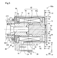
- FIG. 5 is a cross-sectional view showing a detailed configuration of the solenoid of the second embodiment.
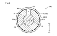
- FIG. 6 is a cross-sectional view taken along the line VI-VI of FIG. FIG.
- FIG. 7 is a cross-sectional view taken along the line VII-VII of FIG.
- FIG. 8 is a cross-sectional view showing a detailed configuration of the solenoid of the third embodiment.
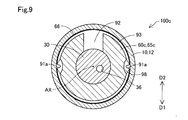
- FIG. 9 is a cross-sectional view showing a detailed configuration of the solenoid of the fourth embodiment.
- the solenoid 100 of the first embodiment shown in FIG. 1 is applied to the linear solenoid valve 300 and functions as an actuator for driving the spool valve 200.
- the linear solenoid valve 300 is used to control the hydraulic pressure of hydraulic oil supplied to an automatic transmission for vehicles (not shown), and is mounted on a valve body provided on the outer surface of a transmission case (not shown).
- the linear solenoid valve 300 of the present embodiment is used by being assembled to the valve body so that the position of the connector 26 described later in the circumferential direction is the ground direction D1.
- the "ground direction D1" means not only the vertical downward direction indicated by the arrow in FIG. 1, but also the vertical downward direction rather than the horizontal direction.
- the connector 26 is formed in the assembled state along the direction rotated at an angle of less than 90 ° with respect to the vertically downward direction.
- the ground direction D1 is preferably ⁇ 45 ° or more and + 45 ° or less with respect to the vertical downward direction.
- the position of the connector 26 in the circumferential direction is determined according to the mounting conditions of the linear solenoid valve 300. Note that FIG. 1 schematically shows a cross section of the linear solenoid valve 300 cut along the central axis AX and the vertical direction.
- the linear solenoid valve 300 includes a spool valve 200 and a solenoid 100 arranged side by side along the central axis AX. Note that FIGS. 1 and 2 show the solenoid 100 and the linear solenoid valve 300 in the non-energized state.
- the linear solenoid valve 300 of the present embodiment is a normally closed type, but may be a normally open type.
- the spool valve 200 shown in FIG. 1 adjusts the opening areas of a plurality of oil ports 214, which will be described later.
- the spool valve 200 includes a sleeve 210, a spool 220, a spring 230, and a spring load adjusting unit 240.
- the sleeve 210 has a substantially cylindrical external shape.
- the sleeve 210 is formed with an insertion hole 212 penetrating along the central axis AX and a plurality of oil ports 214 communicating with the insertion hole 212 and opening in the radial direction.
- a spool 220 is inserted into the insertion hole 212.
- the end of the insertion hole 212 on the solenoid 100 side is formed with an enlarged diameter and functions as an elastic member accommodating portion 218.
- the elastic member 420 which will be described later, is accommodated in the elastic member accommodating portion 218.
- the plurality of oil ports 214 are formed side by side along a direction parallel to the central axis AX (hereinafter, also referred to as "axial direction AD").
- the plurality of oil ports 214 are, for example, an input port that communicates with an oil pump (not shown) to receive an oil supply, an output port that communicates with a clutch piston (not shown) or the like to supply an oil pressure, and a spool 220 according to the output oil pressure. It functions as a feedback port that applies a load to the vehicle, a drain port that discharges hydraulic oil, and so on.
- the outer peripheral surface 211 of the end portion on the solenoid 100 side in the axial direction AD of the sleeve 210 is fastened to the inside of the base portion 80 described later.
- the radial direction means a direction orthogonal to the axial direction AD.
- the spool 220 has a substantially rod-like external shape in which a plurality of large diameter portions 222 and small diameter portions 224 are arranged side by side along the axial direction AD.
- the spool 220 slides along the axial direction AD inside the insertion hole 212, and opens a plurality of oil ports 214 according to the positions of the large diameter portion 222 and the small diameter portion 224 along the axial direction AD. adjust.
- a shaft 90 for transmitting the thrust of the solenoid 100 to the spool 220 is in contact with the end of the spool 220 on the solenoid 100 side.
- a spring 230 is arranged at the other end of the spool 220.
- the spring 230 is composed of a compression coil spring, and presses the spool 220 in the axial direction AD to urge the spool 220 toward the solenoid 100.
- the spring load adjusting unit 240 is arranged in contact with the spring 230, and the amount of screwing into the sleeve 210 is adjusted to adjust the spring load of the spring 230.
- the solenoid 100 shown in FIGS. 1 and 2 is energized and controlled by an electronic control device (not shown) to drive the spool valve 200.
- the solenoid 100 includes a yoke 10, a coil portion 20, a plunger 30, a stator core 40, and a base portion 80.
- the yoke 10 is formed of a magnetic metal and constitutes the outer shell of the solenoid 100.
- the yoke 10 has a bottomed tubular appearance shape, and accommodates the coil portion 20, the plunger 30, and the stator core 40.
- the yoke 10 has a cylindrical portion 12, a bottom portion 14, a thin-walled portion 17, and a notch portion 18.
- the cylindrical portion 12 has a substantially cylindrical external shape along the axial direction AD, and is arranged outside the coil portion 20 in the radial direction.
- a magnetic flux delivery portion 65 which will be described later, is gap-fitted in the cylindrical portion 12.
- the bottom portion 14 is connected to the end portion of the cylindrical portion 12 opposite to the spool valve 200 side and is formed perpendicular to the axial direction AD, and closes the end portion of the cylindrical portion 12.
- the bottom portion 14 is not limited to being perpendicular to the axial direction AD, but may be formed substantially perpendicular to the axial direction AD, or may be formed so as to intersect the axial direction AD according to the shape of the magnetic flux delivery portion 65 described later.
- the bottom portion 14 faces the proximal end surface 34 of the plunger 30, which will be described later.
- the space surrounded by the bottom portion 14, the stator core 40, and the shaft 90 is also referred to as a “plunger chamber 95”.
- the plunger 30 is housed in the plunger room 95.
- annular recess 94 centered on the central axis AX of the yoke 10 is formed on the inner surface of the bottom portion 14.
- the recess 94 is formed including an outer edge of the plunger 30 and a position facing the breathing hole 36 described later and the axial AD, and is configured so that the second breathing path 92 and the breathing hole 36 described later can communicate with each other. ing.
- the thin-walled portion 17 is formed to be thinner than the cylindrical portion 12 at the end of the cylindrical portion 12 on the spool valve 200 side.
- the thin portion 17 constitutes an opening of the yoke 10.
- the cutout portion 18 is formed by cutting out a part of the thin-walled portion 17 in the circumferential direction.
- the notch 18 of the present embodiment is formed so as to be in the ground direction D1 in the circumferential direction in a state where the solenoid 100 is assembled (hereinafter, also referred to as an “assembled state”).
- the notch 18 exposes the connector 26, which will be described later, from the yoke 10.
- the notch portion 18 functions as an inflow portion for flowing a fluid existing in the mounting environment of the solenoid 100 from the outside of the solenoid 100 into the inside of the solenoid 100.
- the fluid existing in the mounting environment of the solenoid 100 corresponds to a fluid such as hydraulic oil or air.
- the fluid that has flowed into the solenoid 100 through the notch 18 can also flow out to the outside of the solenoid 100 through the notch 18. That is, as the plunger 30 slides, the fluid can flow inside and outside the solenoid 100 through the notch 18.
- the coil portion 20 has a substantially cylindrical appearance shape, and is arranged inside the cylindrical portion 12 of the yoke 10 in the radial direction.
- the coil portion 20 has a coil 21 and a bobbin 22.
- the coil 21 is formed of a conducting wire having an insulating coating.
- the bobbin 22 is made of resin, and the coil 21 is wound around the bobbin 22.
- the bobbin 22 is connected to a connector 26 arranged on the outer peripheral portion of the yoke 10.
- the connector 26 is exposed radially outward from the yoke 10 via the notch 18.
- a connection terminal 24 to which the end of the coil 21 is connected is arranged.
- the connector 26 electrically connects the solenoid 100 and the electronic control device via a connection line (not shown).
- the coil portion 20 generates a magnetic force when energized, and a loop-shaped magnetic flux flows through the cylindrical portion 12 of the yoke 10, the bottom portion 14 of the yoke 10, the stator core 40, the plunger 30, and the base portion 80. (Hereinafter, also referred to as "magnetic circuit") is formed.
- magnetic circuit also referred to as "magnetic circuit"
- FIGS. 1 and 2 the coil portion 20 is not energized and the magnetic circuit is not formed.
- the magnetic circuit formed when the coil portion 20 is energized is executed.
- a part of C1 is schematically shown by a thick arrow in FIG.
- the outer diameter of the coil portion 20 is formed to be smaller than the inner diameter of the cylindrical portion 12 of the yoke 10. With such a configuration, a radial gap is formed over the entire circumference between the inner surface of the cylindrical portion 12 and the outer surface of the coil portion 20, and the first respiration of the magnetic flux delivery portion 65, which will be described later. It functions as a breathing passage 28 that communicates the road 91 with the outside of the solenoid 100.
- the breathing passage 28 communicates with the outside of the solenoid 100 through the notch 18 of the yoke 10 to circulate the fluid existing in the mounting environment of the solenoid 100.
- the notch 18 when the notch 18 is immersed in the hydraulic oil, the hydraulic oil as a fluid is circulated, and the notch 18 is located vertically above the storage level of the hydraulic oil. Circulates air as a fluid.
- the plunger 30 is housed in the plunger room 95.
- the plunger 30 has a substantially columnar appearance shape and is made of a magnetic metal.
- the plunger 30 slides on the inner peripheral surface of the core portion 61 of the stator core 40, which will be described later, in the axial direction AD.
- the shaft 90 described above is arranged in contact with the end surface (hereinafter, also referred to as “tip surface 32”) of the plunger 30 on the spool valve 200 side.
- tip surface 32 the end surface of the plunger 30 on the spool valve 200 side.
- the end surface of the plunger 30 opposite to the front end surface 32 faces the bottom portion 14 of the yoke 10.
- the plunger 30 is formed with a breathing hole 36 penetrating in the axial direction AD.
- the breathing hole 36 allows fluids located on the proximal end surface 34 side and the distal end surface 32 side of the plunger 30 to flow in the plunger chamber 95.
- the stator core 40 is made of a magnetic metal and is arranged between the coil portion 20 and the plunger 30.
- the stator core 40 is composed of a member in which a magnetic attraction core 50, a sliding core 60, and a magnetic flux passage suppressing portion 70 are integrated.
- the magnetic attraction core 50 is arranged so as to surround the shaft 90 in the circumferential direction.
- the magnetic attraction core 50 constitutes a portion of the stator core 40 on the spool valve 200 side, and magnetically attracts the plunger 30 by the magnetic force generated by the coil portion 20.
- a stopper 55 is arranged on the surface of the magnetic attraction core 50 facing the tip surface 32 of the plunger 30.
- the stopper 55 is made of a non-magnetic material and suppresses the direct contact between the plunger 30 and the magnetic attraction core 50, and prevents the plunger 30 from being separated from the magnetic attraction core 50 by magnetic attraction.
- the sliding core 60 constitutes a portion of the stator core 40 on the bottom 14 side, and is arranged on the outer side in the radial direction of the plunger 30.
- the sliding core 60 has a core portion 61 and a magnetic flux delivery portion 65.
- the core portion 61 has a substantially cylindrical appearance shape, and is arranged between the coil portion 20 and the plunger 30 in the radial direction.
- the core portion 61 guides the movement of the plunger 30 along the axial AD.
- the plunger 30 slides directly on the inner peripheral surface of the core portion 61.
- the end of the sliding core 60 which is opposite to the magnetic attraction core 50 side (hereinafter, also referred to as “core end 62”), faces the bottom 14 and is in contact with the bottom 14.
- FIG. 2 shows a cross section including the second respiratory passage 92 formed in the vertical direction D2, which will be described later, and the sliding core 60 and the bottom portion 14 are not in contact with each other in the second respiratory passage 92.
- the magnetic flux delivery portion 65 is formed from the core end portion 62 toward the outer side in the radial direction over the entire circumference of the core end portion 62. Therefore, the magnetic flux delivery portion 65 is located between the bobbin 22 and the bottom portion 14 of the yoke 10 in the axial direction AD.
- the magnetic flux transfer unit 65 transfers the magnetic flux between the yoke 10 and the plunger 30 via the core unit 61. More specifically, the magnetic flux transfer portion 65 of the present embodiment transfers the magnetic flux between the bottom portion 14 of the yoke 10 and the plunger 30.
- the magnetic flux delivery portion 65 of this embodiment is integrally formed with the core portion 61 by forging.
- the magnetic flux delivery portion 65 and the core portion 61 may be integrated after being formed as separate bodies from each other.
- the core portion 61 may be press-fitted into the through hole of the magnetic flux delivery portion 65 formed in a ring shape, or may be fixed by welding or the like after the core portion 61 is inserted.
- the magnetic flux transfer portion 65 is gap-fitted into the cylindrical portion 12 of the yoke 10. In other words, the clearance between the outer diameter of the magnetic flux delivery portion 65 and the inner diameter of the cylindrical portion 12 is formed so that a gap can be fitted.
- a first respiratory path 91 is formed on the outer peripheral surface 66 of the magnetic flux delivery portion 65 along the axial direction AD.
- the first respiratory tract 91 communicates with the respiratory passage 28.
- the number of the first respiratory passages 91 formed on the outer peripheral surface 66 of the magnetic flux delivery portion 65 is one.
- the first respiratory tract 91 has a linear groove shape, and is formed so as to be located in the vertical direction D2 in a state where the solenoid 100 is assembled.
- the "heavenly direction D2" is not limited to the vertically upward direction indicated by the arrow in FIG. 3, but means a direction on the vertically upward direction side rather than the horizontal direction.
- the first respiratory tract 91 is formed along the direction rotated at an angle of less than 90 ° with respect to the vertically upward direction in the assembled state.
- the top direction D2 is preferably ⁇ 45 ° or more and + 45 ° or less with respect to the vertically upward direction.
- the magnetic flux delivery portion 65 is formed with a first facing surface 68 facing the bottom portion 14 of the yoke 10.
- a second respiratory path 92 is formed on the first facing surface 68 of the magnetic flux delivery portion 65 along the radial direction.
- the second respiratory tract 92 is formed to communicate the first respiratory tract 91 with the plunger chamber 95.
- the second respiratory tract 92 is formed as a groove whose depth direction is the axial direction AD on the first facing surface 68.
- the second respiratory tract 92 is formed so that the position in the circumferential direction is the same as that of the first respiratory tract 91.
- the second respiratory tract 92 is formed in a range that is in the vertical direction D2 when the solenoid 100 is assembled. Further, in the present embodiment, the second respiratory tract 92 has a linear groove shape along the vertical direction.
- the portion of the bottom portion 14 of the yoke 10 facing the first facing surface 68 is also referred to as a “second facing surface 19” as shown in FIG.
- the magnetic flux passage suppressing portion 70 shown in FIG. 2 is formed between the magnetic attraction core 50 and the core portion 61 in the axial direction AD.
- the magnetic flux passage suppressing unit 70 suppresses the flow of magnetic flux directly between the core unit 61 and the magnetic attraction core 50.
- the magnetic flux passage suppressing portion 70 of the present embodiment is configured such that the magnetic flux passage suppressing portion 70 is formed so that the thickness of the stator core 40 in the radial direction is thin, so that the magnetic resistance is larger than that of the magnetic attraction core 50 and the core portion 61.
- the magnetic flux passage suppressing unit 70 may have a configuration in which the magnetic attraction core 50 and the sliding core 60, which are formed as separate bodies from each other, are physically connected by a non-magnetic material.
- the stator core 40 is urged toward the bottom 14 side in the axial direction AD by the elastic member 420 accommodated in the elastic member accommodating portion 218 formed in the sleeve 210 of the spool valve 200.
- the elastic member 420 is arranged in contact with the end face of the magnetic attraction core 50 in the axial direction AD and on the side opposite to the plunger 30 side.
- the elastic member 420 is composed of a compression coil spring having a substantially cylindrical appearance shape.
- a spool 220 is inserted inside the elastic member 420 in the radial direction.
- the stator core 40 is urged in the axial direction AD toward the bottom 14 side of the yoke 10 by the elastic member 420, the magnetic flux delivery portion 65 is pressed against the bottom 14 and from the bottom 14 of the yoke 10 to the magnetic flux delivery portion 65. The loss of the transmitted magnetic flux is suppressed.
- the base portion 80 is an end portion of the magnetic attraction core 50 of the stator core 40 in the axial direction AD and opposite to the side facing the tip surface 32 (hereinafter, also referred to as “magnetic attraction core end portion 52”). It is arranged on the outer side in the radial direction of.
- the base portion 80 has a substantially tubular appearance shape and is made of a magnetic metal.
- the base portion 80 transfers magnetic flux between the magnetic attraction core 50 of the stator core 40 and the cylindrical portion 12 of the yoke 10.
- the base portion 80 has a first cylinder portion 86 and a collar portion 87.
- the outer peripheral surface 211 of the sleeve 210 is press-fitted into the first tubular portion 86 and fastened to the outer peripheral surface 211.
- the collar portion 87 is connected to the first cylinder portion 86 in the axial direction AD, and has an outer diameter larger than the outer diameter of the first cylinder portion 86.
- the flange portion 87 is arranged outside the magnetic attraction core end portion 52 of the magnetic attraction core 50 in the radial direction, and is in contact with the inner peripheral surface of the cylindrical portion 12 of the yoke 10.
- the inner diameter of the first cylinder portion 86 is larger than the inner diameter of the flange portion 87, and the inner peripheral surface 81 of the first cylinder portion 86 and the inner peripheral surface 82 of the collar portion 87 are substantially parallel in the radial direction. It is connected by a connecting surface 83.
- the connecting surface 83 is in contact with the end surface of the sleeve 210 in the axial direction AD.
- the yoke 10, the plunger 30, the stator core 40, and the base portion 80 are each made of iron, but are not limited to iron and are made of any magnetic material such as nickel or cobalt. May be good.
- the outer peripheral surface of the plunger 30 is plated. By such a plating treatment, the surface hardness of the plunger 30 can be increased, and deterioration of slidability can be suppressed.
- the yoke 10 is formed into a cup shape by press molding, and the stator core 40 is formed by forging, but each may be formed by any molding method.
- the yoke 10 may be integrated by caulking or press-fitting after the cylindrical portion 12 and the bottom portion 14 are formed separately from each other.
- the solenoid 100 of the present embodiment is assembled by inserting the members housed inside the yoke 10 in order from the opening formed by the thin portion 17 of the yoke 10. More specifically, first, the stator core 40 in which the plunger 30 is housed inside the core portion 61 in the radial direction is inserted into the inside of the yoke 10 through the opening. At this time, the magnetic flux delivery portion 65 is gap-fitted into the cylindrical portion 12 of the yoke 10. Therefore, it is possible to prevent the central axis AX of the stator core 40 and the central axis AX of the yoke 10 from being displaced during assembly.
- the coil portion 20 is inserted, and the base portion 80 is gap-fitted with the magnetic attraction core end portion 52 on the inner peripheral surface 82 of the flange portion 87.
- the thin-walled portion 17 in contact with the outer peripheral surface 84 of the flange portion 87 is caulked and fixed to the base portion 80, so that the assembly of the solenoid 100 is completed.
- the cylindrical portion 12 of the yoke 10 and the base portion 80 may be fixed by any method such as welding.
- the base portion 80 is not limited to the gap fitting, and may be fitted with the magnetic attraction core end portion 52 by providing a slight gap in the radial direction.
- FIGS. 1 and 2 show a state in which the plunger 30 is farthest from the magnetic attraction core 50 without energizing the coil 21.
- the magnetic circuit C1 is formed inside the solenoid 100.
- the plunger 30 is attracted to the magnetic attraction core 50 side by the formation of the magnetic circuit C1 and slides on the inner peripheral surface of the core portion 61 in the axial direction AD.
- the current flowing through the coil portion 20 increases, the magnetic flux density of the magnetic circuit C1 increases, and the stroke amount of the plunger 30 increases.
- the opening area of the oil port 214 is adjusted, and the oil pressure proportional to the current value flowing through the coil 21 is output.
- the fluid such as hydraulic oil existing in the mounting environment of the solenoid 100 is charged with the stroke of the plunger 30, the notch 18, the breathing passage 28, the first breathing passage 91, the second breathing passage 92, the recess 94, and the breathing hole 36. To distribute. Since the plunger chamber 95 and the outside of the solenoid 100 are communicated with each other in this way, the pressure fluctuation of the plunger chamber 95 is suppressed as the plunger 30 slides, and the smooth sliding of the plunger 30 is hindered. Is suppressed.
- the fluid such as hydraulic oil existing in the mounting environment of the solenoid 100 may contain foreign matter such as abrasion powder. Such foreign matter may enter the breathing passage 28 through the notch 18.
- the solenoid 100 of the present embodiment is formed so that the first respiratory passage 91 and the second respiratory passage 92 are in the vertical direction D2 in the assembled state. Therefore, the passage path for the foreign matter flowing into the respiratory passage 28 from the notch 18 located in the ground direction D1 to reach the first respiratory passage 91 and the second respiratory passage 92 located in the vertical direction D2 is relatively long. It has been set for a long time.
- the foreign matter that has flowed into the respiratory passage 28 from the notch 18 located in the ground direction D1 passes through the respiratory passage 28 in the circumferential direction in order to reach the first respiratory passage 91 located in the vertical direction D2. It is necessary to go around for half a lap.
- the "maze structure” means a structure that forms a path that is more complicated and has a longer path length than a linear path.
- the core portion 61 and the magnetic flux delivery portion 65 are integrally formed. Therefore, there is no radial gap between the core portion 61 and the magnetic flux delivery portion 65, and it is possible to prevent the core portion 61 and the magnetic flux delivery portion 65 from being eccentric. Therefore, when the magnetic circuit C1 is configured by energization, it is possible to suppress the occurrence of radial bias in the distribution of the magnetic flux transmitted from the magnetic flux delivery portion 65 to the core portion 61, and from the core portion 61 to the plunger 30. It is possible to suppress the occurrence of radial bias in the distribution of the magnetic flux transmitted to.
- the magnetic flux densities of the magnetic circuit C1 can be made substantially equal in the circumferential direction. Therefore, it is possible to suppress an increase in side force due to a bias in the distribution of magnetic flux, and it is possible to suppress deterioration of the slidability of the plunger 30.
- the magnetic flux delivery section 65 corresponds to the first magnetic flux delivery section in the present disclosure
- the base section 80 corresponds to the second magnetic flux delivery section in the present disclosure.
- the sliding core 60 has a diameter from the tubular core portion 61 arranged radially outside the plunger 30 and the core end portion 62 of the core portion 61. Since the magnetic flux delivery portion 65 is formed toward the outside in the direction and transfers the magnetic flux, there is almost no radial gap between the core portion 61 and the magnetic flux delivery portion 65. Therefore, it is possible to prevent the core portion 61 and the magnetic flux delivery portion 65 from being eccentric. Therefore, the diameter of the distribution of the magnetic flux transmitted from the magnetic flux delivery portion 65 to the plunger 30 via the core portion 61 due to such eccentricity. It is possible to suppress the occurrence of directional bias. Therefore, it is possible to suppress an increase in side force due to a bias in the distribution of magnetic flux.
- the magnetic flux delivery portion 65 is gap-fitted in the cylindrical portion 12 of the yoke 10. Therefore, for example, the central axis of the stator core 40 at the time of assembly is compared with a configuration in which a radial gap between the cylindrical portion 12 and the magnetic flux delivery portion 65 is formed to be relatively large in order to secure a respiratory passage. It is possible to prevent the AX and the central axis AX of the yoke 10 from deviating from each other. Therefore, when assembling the solenoid 100, it is possible to prevent the central axes AX of the magnetic attraction core end portion 52 of the stator core 40, the base portion 80, and the thin-walled portion 17 of the yoke 10 from being displaced from each other.
- the cylinder of the yoke is press-fitted when the magnetic flux transfer portion is inserted through the opening of the yoke in the assembly work.
- High dimensional accuracy is required due to the long insertion distance of the magnetic flux delivery portion along the axial direction AD with respect to the portion.
- a step is provided in the inner diameter of the cylindrical portion of the yoke in order to shorten the insertion distance, the structuring of the yoke becomes complicated.
- the number of parts of the yoke is increased. Will increase and the manufacturing process will be complicated. Further, in the configuration in which the magnetic flux delivery portion is press-fitted into the cylindrical portion of the yoke, high dimensional accuracy is required in order to bring the bottom portion of the yoke into contact with the first facing surface of the magnetic flux delivery portion. A structure that absorbs manufacturing errors is required.
- the solenoid 100 of the first embodiment since the magnetic flux transfer portion 65 is gap-fitted in the cylindrical portion 12 of the yoke 10, high dimensional accuracy is required for the yoke 10 and the sliding core 60. This can be suppressed, and the structure of the yoke 10 can be suppressed from becoming complicated and the number of parts can be suppressed, so that the yoke 10 can be easily formed by press molding.
- the first respiratory passage 91 along the axial direction AD is formed on the outer peripheral surface 66 of the magnetic flux delivery portion 65, and the first facing surface 68 of the magnetic flux delivery portion 65 is along the radial direction.
- the second respiratory tract 92 is formed. Therefore, the respiratory passage 28 and the respiratory hole 36 can be communicated with each other via the first respiratory passage 91 and the second respiratory passage 92, and the fluid can be circulated between the plunger chamber 95 and the outside of the solenoid 100. It is possible to suppress the pressure fluctuation of the plunger chamber 95 due to the sliding of the plunger 30. Therefore, it is possible to prevent the smooth sliding of the plunger 30 from being hindered.
- the first respiratory passage 91 is formed on the outer peripheral surface 66 of the magnetic flux delivery portion 65, when the stator core 40 is inserted into the yoke 10, the position of the first respiratory passage 91 in the circumferential direction is visually observed or the like. Easy to check. Therefore, it is possible to prevent the stator core 40 from being erroneously assembled in the circumferential direction with respect to the yoke 10, and it is possible to prevent the directions of the first respiratory passage 91 and the second respiratory passage 92 from being deviated from the desired directions.
- both the first respiratory passage 91 and the second respiratory passage 92 are formed in the magnetic flux delivery portion 65, the positions of the first respiratory passage 91 and the second respiratory passage 92 in the circumferential direction can be determined only by the stator core 40. Can be specified. Therefore, when assembling the solenoid 100, the step of adjusting the position of the first respiratory passage 91 in the circumferential direction with respect to the second respiratory passage 92 can be omitted.
- the positions of the first respiratory tract 91 and the second respiratory tract 92 are formed to be the same in the circumferential direction, the first respiratory tract 91 and the second respiratory tract 92 are formed in the circumferential direction for communicating with each other.
- the respiratory tract along can be omitted. Therefore, it is possible to prevent the structure of the magnetic flux delivery portion 65 from becoming complicated, and it is possible to suppress an increase in the manufacturing process of the stator core 40.
- the second respiratory passage 92 formed along the radial direction is formed in a range that becomes the vertical direction D2 when the solenoid is assembled, a so-called maze structure can be realized and the second respiratory passage 92 is located in the ground direction D1. It is possible to prevent foreign matter flowing from the notch 18 into the breathing passage 28 from reaching the plunger chamber 95. Therefore, it is possible to prevent the slidability of the plunger 30 from deteriorating due to the foreign matter flowing into the plunger chamber 95.
- the solenoid 100a of the second embodiment shown in FIG. 5 is different from the solenoid 100 of the first embodiment in that it includes a sliding core 60a instead of the sliding core 60.
- the sliding core 60a has a magnetic flux delivery portion 65a instead of the magnetic flux delivery portion 65. Since other configurations are the same as those of the solenoid 100 of the first embodiment, the same configurations are designated by the same reference numerals, and detailed description thereof will be omitted.
- two first respiratory passages 91a are formed on the outer peripheral surface 66 of the magnetic flux delivery portion 65a.
- the two first respiratory tracts 91a are positioned at positions displaced from each other by about 180 ° in the circumferential direction, and both are formed at positions different from those in the heavenly direction D2.
- the first facing surface 68 of the magnetic flux delivery portion 65a is radially within the range of the top direction D2 when the solenoid 100 is assembled.
- a second respiratory tract 92 is formed along the line. Therefore, in the present embodiment, the two first respiratory tracts 91a and the second respiratory tract 92 are formed in different positions in the circumferential direction. In the present embodiment, the second respiratory tract 92 is formed by expanding the flow path toward the side closer to the bottom 14 in the axial direction AD.
- a third respiratory tract 93 is formed in the magnetic flux delivery portion 65a.
- the third respiratory tract 93 communicates the first respiratory tract 91 and the second respiratory tract 92 in the circumferential direction.
- the third respiratory tract 93 is formed at the outer edge of the first facing surface 68 shown in FIG.
- the third respiratory tract 93 is formed at the end of the outer peripheral surface 66 of the magnetic flux delivery portion 65a on the bottom 14 side in the axial direction AD.
- the third respiratory tract 93 is formed over the entire circumferential direction as shown in FIG. 7.
- the fluid flowing into the respiratory passage 28 through the notch 18 passes through the first respiratory passage 91a along the axial direction AD, the third respiratory passage 93 along the circumferential direction, and the second respiratory passage 92 along the radial direction. , Inflow into the plunger room 95 through this order.
- the same effect as that of the first embodiment is obtained.
- the third respiratory path 93 is formed in the magnetic flux delivery portion 65a, and the positions of the first respiratory path 91a and the second respiratory path 92 in the circumferential direction are formed differently from each other, which complicates the maze structure. It is possible to prevent foreign matter contained in the fluid flowing into the first respiratory tract 91a from reaching the second respiratory tract 92.
- the third respiratory tract 93 is formed over the entire circumferential direction, in addition to the range connecting the first respiratory tract 91a and the second respiratory tract 92 in the circumferential direction, the first respiratory tract 91a and the first respiratory tract 91a are formed.
- the third respiratory tract 93 is also located in a range that is not directly connected to the two respiratory tracts 92. Therefore, in the portion of the third respiratory passage 93 located in the ground direction D1, for example, foreign matter contained in the fluid flowing into the first respiratory passage 91a can be deposited. Therefore, it is possible to further suppress the foreign matter contained in the fluid flowing into the first respiratory passage 91a from reaching the second respiratory passage 92.
- the third respiratory passage 93 is formed over the entire circumferential direction, the positions of the first respiratory passage 91a and the second respiratory passage 92 in the circumferential direction are slightly deviated due to manufacturing errors. Even in this case, it is possible to prevent the flow path cross-sectional area from becoming excessively narrow at the communication point between the first respiratory path 91a and the third respiratory path 93 and the communication point between the third respiratory path 93 and the second respiratory path 92. It is possible to suppress an increase in flow path resistance.
- the increase in the resistance value can be suppressed, so that the smooth sliding of the plunger 30 is hindered. Can be suppressed.
- the first respiratory passage 91a is slightly displaced in the circumferential direction due to a manufacturing error. It is possible to suppress that the cross-sectional area of the flow path at the communication point between the respiratory path 91a and the third respiratory path 93 becomes excessively narrow, and it is possible to suppress an increase in the flow path resistance.
- first respiratory passage 91a, the second respiratory passage 92, and the third respiratory passage 93 are all formed in the magnetic flux transfer portion 65a, the first respiratory passage 91a, the second respiratory passage 92, and the third respiratory passage are formed.
- the position in the circumferential direction with 93 can be defined only by the stator core 40. Therefore, when assembling the solenoid 100a, the step of adjusting the position of the first respiratory path 91a with respect to the second respiratory path 92 in the circumferential direction and the position of the third respiratory path 93 with respect to the second respiratory path 92 in the circumferential direction are adjusted.
- the step of adjusting can be omitted.
- the solenoid 100b of the third embodiment shown in FIG. 8 is different from the solenoid 100a of the second embodiment in that it includes a sliding core 60b instead of the sliding core 60a.
- the sliding core 60b has a magnetic flux delivery portion 65b instead of the magnetic flux delivery portion 65a. Since other configurations are the same as those of the solenoid 100a of the second embodiment, the same configurations are designated by the same reference numerals, and detailed description thereof will be omitted.
- FIG. 8 shows a cross section similar to that of FIG. 7, and the cross section corresponding to FIG. 6 is the same as that of the second embodiment.
- a third respiratory passage 93b is formed in the magnetic flux delivery portion 65b.
- the third respiratory tract 93b is formed in a range of about 180 ° centered on the position in the heavenly direction D2 in the circumferential direction. Therefore, the third respiratory tract 93b is formed in a range not including the ground direction D1 in the state where the solenoid 100b is assembled. In other words, the third respiratory tract 93b is formed not including a position deviated by 180 ° from the position where the second respiratory tract 92 is formed in the circumferential direction. With such a configuration, the third respiratory tract 93b is formed only in the range connecting the first respiratory tract 91a and the second respiratory tract 92 in the circumferential direction at the shortest distance.
- the same effect as that of the second embodiment is obtained.
- the third respiratory tract 93b is formed in the circumferential direction without including a range deviated by 180 ° from the position where the second respiratory tract 92 is formed, it is formed over the entire circumferential direction.
- the magnetic flux delivery portion 65b is formed by forging, it is possible to suppress a decrease in the degree of freedom in manufacturing as compared with the above configuration.
- the solenoid 100c of the fourth embodiment shown in FIG. 9 is different from the solenoid 100a of the second embodiment in that it includes a sliding core 60c instead of the sliding core 60a.
- the sliding core 60c has a magnetic flux delivery portion 65c instead of the magnetic flux delivery portion 65c. Since other configurations are the same as those of the solenoid 100a of the second embodiment, the same configurations are designated by the same reference numerals, and detailed description thereof will be omitted.
- FIG. 9 shows a cross section similar to that of FIG. 7, and the cross section corresponding to FIG. 6 is the same as that of the second embodiment.
- the first respiratory passage 91a formed in the magnetic flux delivery portion 65c communicates with the retention portion 98.
- the retention portion 98 is formed so as to be surrounded by the magnetic flux delivery portion 65c and the yoke 10, and retains foreign matter contained in the fluid flowing through the first respiratory passage 91a.
- the retention portion 98 has a circumferential dimension of the end portion of the first respiratory passage 91a on the side close to the bottom portion 14 in the axial direction AD of the first respiratory passage 91a. It is formed so as to be larger than the circumferential dimension of other parts. In other words, the circumferential dimension of the first respiratory tract 91a on the side farther from the bottom 14 is smaller than the circumferential dimension of the first respiratory tract 91a on the side closer to the bottom 14.
- the first respiratory tract 91a is formed so that the dimension in the circumferential direction expands as it approaches the bottom portion 14, but other than the end portion of the first respiratory tract 91a on the side closer to the bottom portion 14.
- the circumferential dimension of the portion may be formed to be constant.
- the same effect as that of the second embodiment is obtained.
- the first respiratory passage 91a communicates with the retention portion 98, foreign matter contained in the fluid flowing into the first respiratory passage 91a can be retained in the retention portion 98. Therefore, since it is possible to suppress the foreign matter from flowing into the third respiratory tract 93, it is possible to prevent the foreign matter from flowing into the plunger chamber 95.
- the first respiratory passage 91a is formed on the outer peripheral surface 66 of the magnetic flux delivery portion 65c, and the retention portion 98 is the peripheral portion of the end portion of the first respiratory passage 91a in the axial direction AD and closer to the bottom portion 14. Since the dimension in the direction is formed to be larger than the dimension in the circumferential direction of the other portion of the axial AD in the first respiratory tract 91a, the retention portion 98 can be easily formed by forging.
- E. Other embodiments E-1.
- Other Embodiment 1 The configurations of the first respiratory tract 91, 91a and the second respiratory tract 92 in each of the above embodiments are merely examples and can be changed in various ways.
- the first respiratory passages 91, 91a are formed on the inner peripheral surface of the cylindrical portion 12 of the yoke 10 in place of the outer peripheral surface 66 of the magnetic flux delivery portions 65, 65a to 65a, or in addition to the outer peripheral surface 66. May be good.
- the first respiratory tracts 91 and 91a may be one, or two or more arbitrary number of grooves may be formed side by side in the circumferential direction.
- the second respiratory passage 92 replaces the first facing surface 68 of the magnetic flux delivery portions 65, 65a to 65a, or in addition to the first facing surface 68, the second facing surface 19 of the bottom portion 14 of the yoke 10. It may be formed in. Further, for example, the number of the second respiratory tract 92 is not limited to one, and an arbitrary number of two or more grooves may be formed side by side in the circumferential direction. Further, for example, the second respiratory tract 92 may be formed in a range that does not become the heavenly direction D2 in the circumferential direction when the solenoids 100 and 100a to 100c are assembled.
- first respiratory passage 91, 91a and the second respiratory passage 92 are not limited to the linear groove shape, respectively, and may have an arbitrary groove shape such as a curved shape or a wave shape. That is, in general, at least one first respiratory path 91, 91a along the axial AD is provided on at least one of the outer peripheral surfaces 66 of the magnetic flux delivery portions 65, 65a to 65a and the inner peripheral surface of the cylindrical portion 12.
- first facing surface 68 facing the bottom 14 at the magnetic flux delivery portions 65, 65a to c, and the second facing surface 19 facing the bottom 14 at the bottom 14 At least one of them may be formed with a second respiratory passage 92 along the radial direction for communicating the inside of the magnetic flux delivery portions 65, 65a to 65a in the radial direction with the first respiratory passages 91, 91a.
- a second respiratory passage 92 along the radial direction for communicating the inside of the magnetic flux delivery portions 65, 65a to 65a in the radial direction with the first respiratory passages 91, 91a.
- Embodiment 2 In the solenoids 100a to 100c of the second to fourth embodiments, the third respiratory passages 93 and 93b are formed in the magnetic flux delivery portions 65a to 65c, but instead of the magnetic flux delivery portions 65a to c or the magnetic flux delivery portion. In addition to 65a to 65c, it may be formed on the inner peripheral surface of the cylindrical portion 12 of the yoke 10 or on the second facing surface 19 of the bottom portion 14. That is, in general, at least one of the magnetic flux delivery portions 65a to c and the yoke 10 is formed with third respiratory passages 93 and 93b for communicating the first respiratory passage 91a and the second respiratory passage 92 in the circumferential direction. It may have been done. Even with such a configuration, the same effect as that of each of the above-described embodiments can be obtained.
- Embodiment 3 In the solenoid 100c of the fourth embodiment, the circumferential dimension of the end portion of the first respiratory passage 91a on the side close to the bottom portion 14 is the axial direction AD of the first respiratory passage 91a.
- the staying portion 98 is formed to be larger than the circumferential dimension of the other portion, but the present disclosure is not limited to this.
- an arbitrary retention portion 98 capable of retaining foreign matter contained in the fluid flowing through the first respiratory passages 91 and 91a on the inner peripheral surface of the cylindrical portion 12 of the yoke 10 and the second facing surface 19 of the bottom portion 14. May be formed. Even with such a configuration, the same effect as that of the fourth embodiment can be obtained.
- Embodiment 4 The configurations of the solenoids 100 and 100a to 100c of each of the above embodiments are merely examples and can be changed in various ways.
- the recess 94 of the yoke 10 is not limited to the annular shape, and may be formed in any shape that allows the second respiratory passage 92 and the respiratory hole 36 to communicate with each other.
- a convex portion protruding toward the plunger 30 side may be formed on the central axis AX of the bottom portion 14.
- any radial through hole formed in the cylindrical portion 12 of the yoke 10 is present in the mounting environment of the solenoids 100, 100a-c. It may function as an inflow part of the fluid.
- the elastic member 420 is not limited to the compression coil spring, and may be composed of any elastic member such as a disc spring or a leaf spring. Instead of the elastic member accommodating portion 218, the elastic member 420 may be formed with the coil portion 20 in the axial direction AD.
- the magnetic flux delivery portions 65, 65a to c may be urged by being arranged between the magnetic flux delivery portions 65, 65a to c.
- the inner diameter of the base portion 80 may be substantially constant in the axial direction AD.
- a collar portion whose diameter is enlarged outward in the radial direction is formed at the end portion of the sleeve 210, and the collar portion is formed. It may be fixed to each other with the thin portion 17 of the yoke 10. Even with such a configuration, the same effect as that of each of the above-described embodiments can be obtained.
- Embodiment 5 The solenoids 100 and 100a to 100c of each of the above embodiments are assembled and used so that the positions of the connector 26 and the notch 18 in the circumferential direction are the ground direction D1, but the solenoids 100 and 100a to c are not limited to the ground direction D1 and are used in any direction. It may be assembled and used so as to be. Further, the solenoids 100, 100a to 100c of each of the above embodiments are applied to the linear solenoid valve 300 for controlling the hydraulic pressure of the hydraulic oil supplied to the automatic transmission for vehicles, and function as an actuator for driving the spool valve 200. However, the present disclosure is not limited to this.
- valve body provided on the outer surface of a transmission case, and may be mounted on any hydraulic device that requires control of flood control.
- an arbitrary valve such as a poppet valve may be driven, and instead of the valve, an arbitrary driven body such as a switch may be driven.
- the present disclosure is not limited to each of the above-described embodiments, and can be realized with various configurations within a range that does not deviate from the purpose.
- the technical features in each embodiment corresponding to the technical features in the embodiments described in the column of the outline of the invention may be used to solve some or all of the above-mentioned problems, or one of the above-mentioned effects. It is possible to replace or combine as appropriate to achieve part or all. Further, if the technical feature is not described as essential in the present specification, it can be deleted as appropriate.
Abstract
ソレノイド(100、100a~100c)は、コイル部(20)と、円筒部(12)と底部(14)とを有しコイル部を収容するヨーク(10)と、軸方向(AD)に摺動するプランジャ(30)と、ステータコア(40)であって、磁気吸引コア(50)と、プランジャを収容する筒状のコア部(61)とコア端部(62)から径方向の外側に向かって形成されヨークとコア部との間における磁束の受け渡しを行なう第1磁束受渡部(65、65a~65c)と、を有する摺動コア(60、60a~60c)と、摺動コアと磁気吸引コアとの間における磁束の通過を抑制する磁束通過抑制部(70)と、を有するステータコアと、磁気吸引コア端部(52)の径方向の外側に配置され磁気吸引コアと円筒部との間における磁束の受け渡しを行なう第2磁束受渡部(80)と、を備え、円筒部には、第1磁束受渡部が隙間嵌めされている。
Description
本出願は、2019年11月28日に出願された日本出願番号2019-214976号に基づくもので、ここにその記載内容を援用する。
本開示は、ソレノイドに関する。
従来から、通電により磁力を発生するコイルの内側において、ステータコアの内側をプランジャが摺動するソレノイドが知られている。特許文献1に記載のソレノイドでは、ヨークの底部側において、ステータコアの外周に磁性体のリングコアが配置されている。これにより、ヨーク等の磁気回路部品とステータコアとをリングコアを介して磁気結合させ、磁気回路部品とステータコアとの間の組付隙間に起因する磁力低下を抑制している。
本願発明者らは、特許文献1に記載のソレノイドではリングコアが径方向に移動可能に構成されているため、摺動コアに対してリングコアが偏心して組み付けられると、摺動コアとリングコアとの間の隙間の大きさに径方向の偏りが発生するおそれがあることを見出した。これにより、リングコアを通って摺動コアとプランジャとに伝達される磁束の分布に径方向の偏りが発生し、径方向への吸引力がサイドフォースとして発生するおそれがあることを、本願発明者らは考えた。サイドフォースが増大すると、プランジャの摺動性が悪化するおそれがある。このため、本願発明者らは、ヨークの底部側においてステータコアの外周に設けられていたリングコアを摺動コアと一体化させるとともに、ヨークの開口部側との磁束の受け渡しを行なうベース部をステータコアと別体化させる構成を想定した。しかしながら、かかる構成において、リングコアとヨークとの間に径方向の隙間を設けて呼吸路を確保すると、組み付けの際にステータコアの中心軸とヨークの中心軸とがずれることにより、ステータコアの外周面とヨークの開口部の内周面との間にベース部を挿入する際の組み付け性が悪化するおそれがあることを本願発明者らは見出した。このため、サイドフォースによる摺動性の悪化を抑制しつつ、組み付け性の悪化を抑制できる技術が望まれる。
本開示は、以下の形態として実現することが可能である。
本開示の一形態によれば、ソレノイドが提供される。このソレノイドは、通電により磁力を発生するコイル部と、軸方向に沿った円筒部と、前記軸方向と交差する方向に沿って形成された底部と、を有し、前記コイル部を収容するヨークと、前記軸方向に摺動する柱状のプランジャと、ステータコアであって、前記軸方向において前記プランジャの先端面と対向して配置されて前記コイル部が発生する磁力により前記プランジャを磁気吸引する磁気吸引コアと、前記軸方向と直交する径方向において前記コイル部の内側に配置されて前記プランジャを収容する筒状のコア部と、前記コア部の前記軸方向の端部であって前記底部と対向するコア端部から前記径方向の外側に向かって形成され、前記ヨークと前記コア部との間における磁束の受け渡しを行なう第1磁束受渡部と、を有する摺動コアと、前記摺動コアと前記磁気吸引コアとの間における磁束の通過を抑制する磁束通過抑制部と、を有するステータコアと、前記磁気吸引コアの前記軸方向の端部であって前記先端面と対向する側とは反対側の磁気吸引コア端部の前記径方向の外側に配置され、前記磁気吸引コアと前記円筒部との間における磁束の受け渡しを行なう第2磁束受渡部と、を備え、前記円筒部には、前記第1磁束受渡部が隙間嵌めされている。
この形態のソレノイドによれば、摺動コアが、プランジャに対して径方向外側に配置された筒状のコア部と、コア部のコア端部から径方向外側に向かって形成されて磁束の受け渡しを行なう第1磁束受渡部とを有するので、コア部と第1磁束受渡部との間に径方向の隙間がほぼ存在しない。このため、コア部と第1磁束受渡部とが偏心することを抑制できるので、かかる偏心に起因してコア部を介して第1磁束受渡部からプランジャへと伝達される磁束の分布に径方向の偏りが発生することを抑制できる。したがって、磁束の分布の偏りによるサイドフォースの増大を抑制できる。加えて、ヨークの円筒部に第1磁束受渡部が隙間嵌めされているので、例えば呼吸路を確保するために円筒部と第1磁束受渡部との間の径方向の隙間が比較的大きく形成されている構成と比較して、組み付けの際にステータコアの中心軸とヨークの中心軸とがずれることを抑制できる。このため、ソレノイドの組み付けの際に、ステータコアにおける磁気吸引コア端部と、第2磁束受渡部と、ヨークの円筒部とのそれぞれの中心軸が互いにずれることを抑制できるので、組み付け性の悪化を抑制できる。したがって、サイドフォースによる摺動性の悪化を抑制しつつ、組み付け性の悪化を抑制できる。
本開示は、種々の形態で実現することも可能である。例えば、ソレノイドバルブ、ソレノイドの製造方法等の形態で実現することができる。
本開示についての上記目的およびその他の目的、特徴や利点は、添付の図面を参照しながら下記の詳細な記述により、より明確になる。その図面は、
図1は、第1実施形態のソレノイドが適用されたリニアソレノイドバルブの概略構成を示す断面図であり、
図2は、ソレノイドの詳細構成を示す断面図であり、
図3は、図2のIII-III線に沿った断面図であり、
図4は、図2のIV-IV線に沿った断面図であり、
図5は、第2実施形態のソレノイドの詳細構成を示す断面図であり、
図6は、図5のVI-VI線に沿った断面図であり、
図7は、図5のVII-VII線に沿った断面図であり、
図8は、第3実施形態のソレノイドの詳細構成を示す断面図であり、
図9は、第4実施形態のソレノイドの詳細構成を示す断面図である。
A.第1実施形態:
図1に示す第1実施形態のソレノイド100は、リニアソレノイドバルブ300に適用され、スプール弁200を駆動させるアクチュエータとして機能する。リニアソレノイドバルブ300は、図示しない車両用自動変速機に供給する作動油の油圧を制御するために用いられ、図示しないトランスミッションケースの外側面に設けられたバルブボディに搭載されている。本実施形態のリニアソレノイドバルブ300は、後述するコネクタ26の周方向の位置が地方向D1となるようにバルブボディに組み付けられて用いられている。本実施形態において、「地方向D1」とは、図1において矢印で示す鉛直下方向に限らず、水平方向よりも鉛直下方向側の方向を意味している。このため、コネクタ26は、組み付け状態において、鉛直下方向に対して90°未満の角度で回転させた方向に沿って形成されている。なお、地方向D1は、鉛直下方向に対して-45°以上+45°以下であることが望ましい。コネクタ26の周方向の位置は、リニアソレノイドバルブ300の搭載条件に応じて定められている。なお、図1では、中心軸AXおよび鉛直方向に沿ってリニアソレノイドバルブ300を切断した断面を模式的に示している。
図1に示す第1実施形態のソレノイド100は、リニアソレノイドバルブ300に適用され、スプール弁200を駆動させるアクチュエータとして機能する。リニアソレノイドバルブ300は、図示しない車両用自動変速機に供給する作動油の油圧を制御するために用いられ、図示しないトランスミッションケースの外側面に設けられたバルブボディに搭載されている。本実施形態のリニアソレノイドバルブ300は、後述するコネクタ26の周方向の位置が地方向D1となるようにバルブボディに組み付けられて用いられている。本実施形態において、「地方向D1」とは、図1において矢印で示す鉛直下方向に限らず、水平方向よりも鉛直下方向側の方向を意味している。このため、コネクタ26は、組み付け状態において、鉛直下方向に対して90°未満の角度で回転させた方向に沿って形成されている。なお、地方向D1は、鉛直下方向に対して-45°以上+45°以下であることが望ましい。コネクタ26の周方向の位置は、リニアソレノイドバルブ300の搭載条件に応じて定められている。なお、図1では、中心軸AXおよび鉛直方向に沿ってリニアソレノイドバルブ300を切断した断面を模式的に示している。
リニアソレノイドバルブ300は、中心軸AXに沿って互いに並んで配置されたスプール弁200とソレノイド100とを備える。なお、図1および図2では、非通電状態のソレノイド100およびリニアソレノイドバルブ300を示している。本実施形態のリニアソレノイドバルブ300は、ノーマリクローズタイプであるが、ノーマリオープンタイプであってもよい。
図1に示すスプール弁200は、後述する複数のオイルポート214の開口面積を調整する。スプール弁200は、スリーブ210と、スプール220と、バネ230と、バネ荷重調整部240とを備える。
スリーブ210は、略円筒状の外観形状を有する。スリーブ210には、中心軸AXに沿って貫通する挿入孔212と、挿入孔212と連通して径方向に開口する複数のオイルポート214とが形成されている。挿入孔212には、スプール220が挿入されている。挿入孔212のソレノイド100側の端部は、拡径して形成され、弾性部材収容部218として機能する。弾性部材収容部218には、後述する弾性部材420が収容される。複数のオイルポート214は、中心軸AXと平行な方向(以下、「軸方向AD」とも呼ぶ)に沿って互いに並んで形成されている。複数のオイルポート214は、例えば、図示しないオイルポンプと連通して油圧の供給を受ける入力ポート、図示しないクラッチピストン等と連通して油圧を供給する出力ポート、出力される油圧に応じてスプール220に負荷荷重を付与するフィードバックポート、作動油を排出するドレインポート等として機能する。スリーブ210の軸方向ADにおけるソレノイド100側の端部の外周面211は、後述するベース部80の内側に締結されている。なお、本実施形態において、径方向とは、軸方向ADに直交する方向を意味している。
スプール220は、軸方向ADに沿って複数の大径部222と小径部224とが並んで配置された略棒状の外観形状を有する。スプール220は、挿入孔212の内部において軸方向ADに沿って摺動し、大径部222と小径部224との軸方向ADに沿った位置に応じて、複数のオイルポート214の開口面積を調整する。スプール220のソレノイド100側の端部には、ソレノイド100の推力をスプール220に伝達するためのシャフト90が当接して配置されている。スプール220の他端には、バネ230が配置されている。バネ230は、圧縮コイルスプリングにより構成され、スプール220を軸方向ADに押圧してソレノイド100側へと付勢している。バネ荷重調整部240は、バネ230と当接して配置され、スリーブ210に対するねじ込み量が調整されることにより、バネ230のバネ荷重を調整する。
図1および図2に示すソレノイド100は、図示しない電子制御装置によって通電制御されて、スプール弁200を駆動する。ソレノイド100は、ヨーク10と、コイル部20と、プランジャ30と、ステータコア40と、ベース部80とを備える。
図2に示すように、ヨーク10は、磁性体の金属により形成され、ソレノイド100の外郭を構成している。ヨーク10は、有底筒状の外観形状を有し、コイル部20とプランジャ30とステータコア40とを収容する。ヨーク10は、円筒部12と、底部14と、薄肉部17と、切欠部18とを有する。
円筒部12は、軸方向ADに沿った略円筒状の外観形状を有し、コイル部20の径方向外側に配置されている。円筒部12には、後述する磁束受渡部65が隙間嵌めされている。
底部14は、円筒部12のスプール弁200側とは反対側の端部に連なって軸方向ADと垂直に形成され、円筒部12の端部を閉塞している。なお、底部14は、軸方向ADと垂直に限らず、略垂直に形成されてもよく、後述する磁束受渡部65の形状に応じて軸方向ADと交差して形成されてもよい。底部14は、後述するプランジャ30の基端面34と対向している。以下の説明では、底部14とステータコア40とシャフト90とにより囲まれる空間を「プランジャ室95」とも呼ぶ。プランジャ室95には、プランジャ30が収容されている。本実施形態において、底部14の内側面には、ヨーク10の中心軸AXを中心とした円環状の凹部94が形成されている。凹部94は、プランジャ30の外縁部および後述する呼吸孔36と軸方向ADに対向する位置を含んで形成されており、後述する第2呼吸路92と呼吸孔36とを互いに連通可能に構成されている。
薄肉部17は、円筒部12におけるスプール弁200側の端部において、円筒部12よりも厚みが薄く形成されている。薄肉部17は、ヨーク10の開口を構成している。
切欠部18は、薄肉部17の周方向の一部が切り欠かれて形成されている。本実施形態の切欠部18は、ソレノイド100が組み付けられた状態(以下、「組み付け状態」とも呼ぶ)において、周方向のうち地方向D1となるように形成されている。切欠部18によって、後述するコネクタ26がヨーク10から露出している。また、切欠部18は、ソレノイド100の搭載環境に存在する流体を、ソレノイド100の外部からソレノイド100の内部へと流入させる流入部として機能する。ソレノイド100の搭載環境に存在する流体には、作動油や空気等の流体が該当する。なお、切欠部18を介してソレノイド100の内部へと流入した流体は、また、切欠部18を介してソレノイド100の外部へと流出することができる。つまり、プランジャ30の摺動に伴って、切欠部18を介してソレノイド100の内部と外部とで流体が流動可能に構成されている。
コイル部20は、略筒状の外観形状を有し、ヨーク10の円筒部12の径方向内側に配置されている。コイル部20は、コイル21とボビン22とを有する。コイル21は、絶縁被覆が施された導線により形成されている。ボビン22は、樹脂により形成され、コイル21が巻回されている。ボビン22は、ヨーク10の外周部に配置されたコネクタ26と連結されている。コネクタ26は、切欠部18を介してヨーク10から径方向外側に露出している。コネクタ26の内部には、コイル21の端部が接続された接続端子24が配置されている。コネクタ26は、図示しない接続線を介してソレノイド100と電子制御装置との電気的な接続を行なう。コイル部20は、通電されることにより磁力を発生し、ヨーク10の円筒部12と、ヨーク10の底部14と、ステータコア40と、プランジャ30と、ベース部80とを通るループ状の磁束の流れ(以下、「磁気回路」とも呼ぶ)を形成させる。図1および図2に示す状態では、コイル部20への通電が実行されず磁気回路が形成されていないが、説明の便宜上、コイル部20への通電が実行された場合に形成される磁気回路C1の一部を、図2において太線の矢印で模式的に示している。
コイル部20の外径は、ヨーク10の円筒部12の内径よりも小さく形成されている。このような構成により、円筒部12の内側面とコイル部20の外側面との間には、全周に亘って径方向の隙間が形成されており、後述する磁束受渡部65の第1呼吸路91とソレノイド100の外部とを連通させる呼吸通路28として機能する。呼吸通路28は、ヨーク10の切欠部18を介してソレノイド100の外部と連通し、ソレノイド100の搭載環境に存在する流体を流通させる。例えば、ソレノイド100の搭載環境として、切欠部18が作動油に浸かっている場合には、流体としての作動油を流通させ、切欠部18が作動油の貯留レベルよりも鉛直上方に位置する場合には、流体としての空気を流通させる。
プランジャ30は、プランジャ室95に収容されている。プランジャ30は、略円柱状の外観形状を有し、磁性体の金属により構成されている。プランジャ30は、後述するステータコア40のコア部61の内周面を軸方向ADに摺動する。プランジャ30のスプール弁200側の端面(以下、「先端面32」とも呼ぶ)には、上述したシャフト90が当接して配置されている。これにより、プランジャ30は、図1に示すスプール220に伝達されるバネ230の付勢力により、軸方向ADに沿ってヨーク10の底部14側へと付勢されている。図2に示すように、プランジャ30の先端面32とは反対側の端面(以下、「基端面34」とも呼ぶ)は、ヨーク10の底部14と対向している。図3に示すように、プランジャ30には、軸方向ADに貫通する呼吸孔36が形成されている。図2に示すように、呼吸孔36は、プランジャ室95において、プランジャ30の基端面34側および先端面32側に位置する流体を流通させる。
ステータコア40は、磁性体の金属により構成され、コイル部20とプランジャ30との間に配置されている。ステータコア40は、磁気吸引コア50と、摺動コア60と、磁束通過抑制部70とが一体化された部材により構成されている。
磁気吸引コア50は、シャフト90を周方向に取り囲んで配置されている。磁気吸引コア50は、ステータコア40のうちスプール弁200側の部分を構成し、コイル部20が発生する磁力によりプランジャ30を磁気吸引する。磁気吸引コア50のうちプランジャ30の先端面32と対向する面には、ストッパ55が配置されている。ストッパ55は、非磁性体により構成され、プランジャ30と磁気吸引コア50とが直接当接することを抑制し、磁気吸引により磁気吸引コア50からプランジャ30が離れなくなることを抑制する。
摺動コア60は、ステータコア40のうち底部14側の部分を構成し、プランジャ30の径方向外側に配置されている。摺動コア60は、コア部61と、磁束受渡部65とを有する。
コア部61は、略円筒状の外観形状を有し、径方向においてコイル部20とプランジャ30との間に配置されている。コア部61は、プランジャ30の軸方向ADに沿った移動をガイドする。これにより、プランジャ30は、コア部61の内周面を直接摺動する。コア部61とプランジャ30との間には、プランジャ30の摺動性を確保するための図示しない摺動ギャップが存在している。摺動コア60の端部であって磁気吸引コア50側とは反対側の端部(以下、「コア端部62」とも呼ぶ)は、底部14と対向して当接している。なお、図2では、後述する天方向D2に形成された第2呼吸路92を含む断面が示されており、かかる第2呼吸路92において摺動コア60と底部14とは当接していない。
磁束受渡部65は、コア端部62の全周に亘って、コア端部62から径方向外側に向かって形成されている。このため、磁束受渡部65は、軸方向ADにおいて、ボビン22とヨーク10の底部14との間に位置している。磁束受渡部65は、コア部61を介してヨーク10とプランジャ30との間における磁束の受け渡しを行なう。より具体的には、本実施形態の磁束受渡部65は、ヨーク10の底部14とプランジャ30との間における磁束の受け渡しを行なう。
本実施形態の磁束受渡部65は、鍛造によって、コア部61と一体に成形されている。なお、磁束受渡部65とコア部61とは、互いに別体として形成された後に一体化されてもよい。例えば、リング状に形成された磁束受渡部65の貫通孔に、コア部61が圧入されてもよく、コア部61が挿入された後に溶接等により固定されてもよい。磁束受渡部65は、ヨーク10の円筒部12に隙間嵌めされている。換言すると、磁束受渡部65の外径と円筒部12の内径とのクリアランスは、隙間嵌めが可能となるように形成されている。
図3に示すように、磁束受渡部65の外周面66には、軸方向ADに沿って第1呼吸路91が形成されている。第1呼吸路91は、呼吸通路28と連通している。本実施形態において、磁束受渡部65の外周面66に形成されている第1呼吸路91の数は、1本である。また、本実施形態において、第1呼吸路91は、直線状の溝形状を有しており、ソレノイド100が組み付けられた状態において天方向D2に位置するように形成されている。本実施形態において、「天方向D2」とは、図3において矢印で示す鉛直上方向に限らず、水平方向よりも鉛直上方向側の方向を意味している。このため、第1呼吸路91は、組み付け状態において、鉛直上方向に対して90°未満の角度で回転させた方向に沿って形成されている。なお、天方向D2は、鉛直上方向に対して-45°以上+45°以下であることが望ましい。
図2に示すように、磁束受渡部65には、ヨーク10の底部14と対向する第1対向面68が形成されている。磁束受渡部65の第1対向面68には、図4に示すように、径方向に沿って第2呼吸路92が形成されている。第2呼吸路92は、第1呼吸路91とプランジャ室95とを連通させるために形成されている。第2呼吸路92は、第1対向面68における軸方向ADを深さ方向とする溝として形成されている。本実施形態において、第2呼吸路92は、第1呼吸路91と周方向の位置が互いに同じに形成されている。このような構成により、第2呼吸路92は、ソレノイド100が組み付けられた状態において天方向D2となる範囲に形成されている。また、本実施形態において、第2呼吸路92は、鉛直方向に沿った直線状の溝形状を有している。以下の説明では、ヨーク10の底部14において第1対向面68と対向する部分を、図2に示すように、「第2対向面19」とも呼ぶ。
図2に示す磁束通過抑制部70は、軸方向ADにおいて、磁気吸引コア50とコア部61との間に形成されている。磁束通過抑制部70は、コア部61と磁気吸引コア50との間で直接的に磁束が流れることを抑制する。本実施形態の磁束通過抑制部70は、ステータコア40の径方向の厚みが薄肉に形成されることにより、磁気吸引コア50およびコア部61よりも磁気抵抗が大きくなるように構成されている。なお、磁束通過抑制部70は、互いに別体として形成された磁気吸引コア50と摺動コア60とを非磁性体により物理的に接続する構成であってもよい。
ステータコア40は、スプール弁200のスリーブ210に形成された弾性部材収容部218に収容される弾性部材420によって、軸方向ADにおいて底部14側へと付勢されている。弾性部材420は、磁気吸引コア50における軸方向ADの端面であってプランジャ30側とは反対側の端面と当接して配置されている。本実施形態において、弾性部材420は、略円筒状の外観形状を有する圧縮コイルバネにより構成されている。弾性部材420の径方向内側には、スプール220が挿入されている。弾性部材420により、ステータコア40がヨーク10の底部14側へと軸方向ADに付勢されるので、磁束受渡部65が底部14へと圧接され、ヨーク10の底部14から磁束受渡部65へと伝達される磁束の損失が抑制される。
ベース部80は、ステータコア40の磁気吸引コア50における軸方向ADの端部であって先端面32と対向する側とは反対側の端部(以下、「磁気吸引コア端部52」とも呼ぶ)の径方向外側に配置されている。ベース部80は、略筒状の外観形状を有し、磁性体の金属により構成されている。ベース部80は、ステータコア40の磁気吸引コア50とヨーク10の円筒部12との間における磁束の受け渡しを行なう。ベース部80は、第1筒部86と、鍔部87とを有する。第1筒部86は、スリーブ210の外周面211が内部に圧入されて外周面211に締結されている。鍔部87は、第1筒部86に対して軸方向ADに接続されており、第1筒部86の外径よりも大きな外径を有する。鍔部87は、磁気吸引コア50の磁気吸引コア端部52の径方向の外側に配置され、ヨーク10の円筒部12の内周面と当接している。本実施形態において、第1筒部86の内径は、鍔部87の内径よりも大きく、第1筒部86の内周面81と鍔部87の内周面82とは、径方向に略平行な接続面83により接続されている。本実施形態では、接続面83には、スリーブ210の軸方向ADの端面が接している。
本実施形態において、ヨーク10と、プランジャ30と、ステータコア40と、ベース部80とは、それぞれ鉄により構成されているが、鉄に限らず、ニッケルやコバルト等、任意の磁性体により構成されてもよい。また、本実施形態において、プランジャ30の外周面には、めっき処理が施されている。かかるめっき処理により、プランジャ30の表面硬度を高めることができ、また、摺動性の悪化を抑制できる。また、本実施形態において、ヨーク10はプレス成形によってカップ形状に形成され、ステータコア40は鍛造により形成されているが、それぞれ任意の成形方法により形成されてもよい。例えば、ヨーク10は、円筒部12と底部14とが互いに別体に形成された後に、かしめ固定や圧入固定等により一体化されてもよい。
本実施形態のソレノイド100は、ヨーク10の内部に収容される部材が、ヨーク10の薄肉部17により形成される開口から順番に挿入されることにより組み付けられる。より具体的には、まず、コア部61の径方向内側にプランジャ30が収容された状態のステータコア40が、開口からヨーク10の内部へと挿入される。このとき、ヨーク10の円筒部12に、磁束受渡部65が隙間嵌めされる。したがって、組み付けの際に、ステータコア40の中心軸AXとヨーク10の中心軸AXとがずれることを抑制できるという効果が得られる。次に、コイル部20が挿入されて、ベース部80が鍔部87の内周面82において磁気吸引コア端部52と隙間嵌めされる。その後、鍔部87の外周面84に当接した状態の薄肉部17がベース部80とかしめ固定されることにより、ソレノイド100の組み付けが完了する。なお、かしめ固定に代えて、溶接等の任意の方法を用いてヨーク10の円筒部12とベース部80とが固定されてもよい。また、ベース部80は、隙間嵌めに限らず、径方向の僅かな隙間を設けて磁気吸引コア端部52と嵌合されていてもよい。
図1および図2では、コイル21への通電が行なわれずに、プランジャ30が磁気吸引コア50から最も遠ざかった状態を示している。図1および図2に示す状態とは異なり、コイル21への通電が行なわれると、ソレノイド100の内部に磁気回路C1が形成される。プランジャ30は、磁気回路C1の形成によって磁気吸引コア50側へと引き寄せられて、コア部61の内周面を軸方向ADに摺動する。コイル部20に流される電流が大きいほど、磁気回路C1の磁束密度が増加し、プランジャ30のストローク量が増加する。
プランジャ30の先端面32に当接するシャフト90は、プランジャ30が磁気吸引コア50側へとストロークすると、図1に示すスプール220をバネ230側へと押圧する。これにより、オイルポート214の開口面積が調整され、コイル21に流される電流値に比例した油圧が出力される。
ソレノイド100の搭載環境に存在する作動油等の流体は、プランジャ30のストロークに伴って、切欠部18、呼吸通路28、第1呼吸路91、第2呼吸路92、凹部94、および呼吸孔36を流通する。このように、プランジャ室95とソレノイド100の外部が連通されているので、プランジャ30の摺動に伴ってプランジャ室95の圧力が変動することが抑制され、プランジャ30の滑らかな摺動が阻害されることが抑制される。
ソレノイド100の搭載環境に存在する作動油等の流体には、摩耗粉等の異物が含まれていることがある。かかる異物は、切欠部18を通って呼吸通路28へと侵入するおそれがある。本実施形態のソレノイド100は、組み付け状態において第1呼吸路91および第2呼吸路92が天方向D2となるように形成されている。このため、地方向D1に位置する切欠部18から呼吸通路28へと流入した異物が、天方向D2に位置する第1呼吸路91および第2呼吸路92に到達するまでの通過経路が比較的長く設定されている。したがって、本実施形態において、地方向D1に位置する切欠部18から呼吸通路28へと流入した異物は、天方向D2に位置する第1呼吸路91に到達するために周方向において呼吸通路28を半周分回り込む必要がある。このように、異物が通過する経路がいわゆる迷路構造を有するので、呼吸通路28へと流入した異物がプランジャ室95へと流入することが抑制されている。本実施形態において、「迷路構造」とは、直線状の経路に比べて複雑であり経路長が長い経路を形成する構造を意味している。
上述のように、本実施形態の摺動コア60は、コア部61と磁束受渡部65とが一体に形成されている。このため、コア部61と磁束受渡部65との間に径方向の隙間が存在せず、コア部61と磁束受渡部65とが偏心することを抑制できる。したがって、通電により磁気回路C1が構成された場合に、磁束受渡部65からコア部61へと伝達される磁束の分布に径方向の偏りが発生することを抑制でき、コア部61からプランジャ30へと伝達される磁束の分布に径方向の偏りが発生することを抑制できる。換言すると、本実施形態のソレノイド100によれば、磁気回路C1の磁束密度を周方向において略等しくできる。このため、磁束の分布の偏りによるサイドフォースの増大を抑制でき、プランジャ30の摺動性の悪化を抑制できる。
本実施形態において、磁束受渡部65は、本開示における第1磁束受渡部に相当し、ベース部80は、本開示における第2磁束受渡部に相当する。
以上説明した第1実施形態のソレノイド100によれば、摺動コア60が、プランジャ30に対して径方向外側に配置された筒状のコア部61と、コア部61のコア端部62から径方向外側に向かって形成されて磁束の受け渡しを行なう磁束受渡部65とを有するので、コア部61と磁束受渡部65との間に、径方向の隙間がほぼ存在しない。このため、コア部61と磁束受渡部65とが偏心することを抑制できるので、かかる偏心に起因してコア部61を介して磁束受渡部65からプランジャ30へと伝達される磁束の分布に径方向の偏りが発生することを抑制できる。したがって、磁束の分布の偏りによるサイドフォースの増大を抑制できる。
加えて、ヨーク10の円筒部12には、磁束受渡部65が隙間嵌めされている。このため、例えば呼吸路を確保するために円筒部12と磁束受渡部65との間の径方向の隙間が比較的大きく形成されている構成と比較して、組み付けの際にステータコア40の中心軸AXとヨーク10の中心軸AXとがずれることを抑制できる。このため、ソレノイド100の組み付けの際に、ステータコア40における磁気吸引コア端部52と、ベース部80と、ヨーク10の薄肉部17とのそれぞれの中心軸AXが互いにずれることを抑制できるので、磁気吸引コア端部52の外周面とヨーク10の薄肉部17の内周面との間にベース部80を挿入する際の組み付け性の悪化を抑制できる。したがって、サイドフォースによる摺動性の悪化を抑制しつつ、組み付け性の悪化を抑制できる。
第1実施形態のソレノイド100とは異なり、ヨークの円筒部に磁束受渡部が圧入される構成においては、組み付け作業において、ヨークの開口から磁束受渡部を挿入して圧入させる際に、ヨークの円筒部に対する磁束受渡部の軸方向ADに沿った挿入距離が長いことに起因して、高い寸法精度が要求されてしまう。また、かかる挿入距離を短くするためにヨークの円筒部の内径に段差を設けると、ヨークの構造化が複雑化してしまう。また、かかる挿入距離を短くするために、ヨークの円筒部と底部とを別体に形成して、ヨークの円筒部の底部側に形成された開口から磁束受渡部を圧入すると、ヨークの部品点数が増加して製造工程が複雑化してしまう。また、ヨークの円筒部に磁束受渡部が圧入される構成においては、ヨークの底部と磁束受渡部の第1対向面とを当接させるために、高い寸法精度が要求されてしまい、また、部品製造上の誤差を吸収させる構造が必要となってしまう。
これに対し、第1実施形態のソレノイド100によれば、ヨーク10の円筒部12に磁束受渡部65が隙間嵌めされているので、ヨーク10や摺動コア60に対して高い寸法精度が要求されることを抑制でき、また、ヨーク10の構造の複雑化や部品点数の増加を抑制できるので、ヨーク10をプレス成形によって容易に形成できる。
また、第1実施形態のソレノイド100では、磁束受渡部65の外周面66に軸方向ADに沿った第1呼吸路91が形成され、磁束受渡部65の第1対向面68に径方向に沿った第2呼吸路92が形成されている。このため、第1呼吸路91および第2呼吸路92を介して呼吸通路28と呼吸孔36とを連通でき、プランジャ室95とソレノイド100の外部との間において流体を流通させることができるので、プランジャ30の摺動に伴ってプランジャ室95の圧力が変動することを抑制できる。したがって、プランジャ30の滑らかな摺動が阻害されることを抑制できる。
また、第1呼吸路91が磁束受渡部65の外周面66に形成されているので、ヨーク10の内部にステータコア40を挿入する際に、第1呼吸路91の周方向の位置を目視等により容易に確認できる。このため、ヨーク10に対するステータコア40の周方向の位置が誤って組み付けられることを抑制でき、第1呼吸路91および第2呼吸路92の方向が所望の方向からずれてしまうことを抑制できる。
また、第1呼吸路91と第2呼吸路92とがいずれも磁束受渡部65に形成されているので、第1呼吸路91および第2呼吸路92の周方向の位置を、ステータコア40のみで規定できる。このため、ソレノイド100の組み付けの際に、第2呼吸路92に対する第1呼吸路91の周方向の位置を調整する工程を省略できる。
また、第1呼吸路91と第2呼吸路92とは、周方向の位置が互いに同じに形成されているので、第1呼吸路91と第2呼吸路92とを連通させるための周方向に沿った呼吸路を省略できる。このため、磁束受渡部65の構造が複雑化することを抑制でき、ステータコア40の製造工程の増加を抑制できる。
また、径方向に沿って形成された第2呼吸路92が、ソレノイドが組み付けられた状態において天方向D2となる範囲に形成されているので、いわゆる迷路構造を実現でき、地方向D1に位置する切欠部18から呼吸通路28へと流入した異物がプランジャ室95に到達することを抑制できる。このため、プランジャ室95に流入した異物に起因してプランジャ30の摺動性が悪化することを抑制できる。
B.第2実施形態:
図5に示す第2実施形態のソレノイド100aは、摺動コア60に代えて摺動コア60aを備える点において、第1実施形態のソレノイド100と異なる。摺動コア60aは、磁束受渡部65に代えて磁束受渡部65aを有している。その他の構成は第1実施形態のソレノイド100と同じであるので、同一の構成には同一の符号を付し、それらの詳細な説明を省略する。
図5に示す第2実施形態のソレノイド100aは、摺動コア60に代えて摺動コア60aを備える点において、第1実施形態のソレノイド100と異なる。摺動コア60aは、磁束受渡部65に代えて磁束受渡部65aを有している。その他の構成は第1実施形態のソレノイド100と同じであるので、同一の構成には同一の符号を付し、それらの詳細な説明を省略する。
図6に示すように、磁束受渡部65aの外周面66には、2本の第1呼吸路91aが形成されている。本実施形態において、2本の第1呼吸路91aは、周方向において互いに約180°ずれた位置であって、いずれも天方向D2とは異なる位置に形成されている。
図5および図7に示すように、磁束受渡部65aの第1対向面68には、第1実施形態と同様に、ソレノイド100が組み付けられた状態において天方向D2となる範囲に、径方向に沿った第2呼吸路92が形成されている。このため、本実施形態において、2つの第1呼吸路91aと第2呼吸路92とは、周方向の位置が互いに異なって形成されている。本実施形態において、第2呼吸路92は、軸方向ADにおいて底部14に近い側に向かって流路が拡大して形成されている。
図7に示すように、磁束受渡部65aには、第3呼吸路93が形成されている。第3呼吸路93は、第1呼吸路91と第2呼吸路92とを周方向に連通させる。本実施形態において、第3呼吸路93は、図5に示す第1対向面68の外縁部に形成されている。換言すると、第3呼吸路93は、磁束受渡部65aの外周面66のうち軸方向ADにおいて底部14側の端部に形成されている。また、本実施形態において、第3呼吸路93は、図7に示すように周方向の全体に亘って形成されている。
切欠部18を介して呼吸通路28へと流入した流体は、軸方向ADに沿った第1呼吸路91a、周方向に沿った第3呼吸路93、径方向に沿った第2呼吸路92を、この順番に通ってプランジャ室95へと流入する。
以上説明した第2実施形態のソレノイド100aによれば、第1実施形態と同様な効果を奏する。加えて、磁束受渡部65aに第3呼吸路93が形成されて、第1呼吸路91aと第2呼吸路92との周方向の位置が互いに異なって形成されているので、迷路構造を複雑化でき、第1呼吸路91aに流入した流体に含まれる異物が第2呼吸路92に到達することを抑制できる。
また、第3呼吸路93が周方向の全体に亘って形成されているので、周方向において第1呼吸路91aと第2呼吸路92とを結ぶ範囲に加えて、第1呼吸路91aと第2呼吸路92とを直接的には結ばない範囲にも第3呼吸路93が位置している。このため、第3呼吸路93のうち、例えば地方向D1に位置する部分については、第1呼吸路91aに流入した流体に含まれる異物を堆積させることができる。したがって、第1呼吸路91aに流入した流体に含まれる異物が第2呼吸路92に到達することをより抑制できる。また、第3呼吸路93が周方向の全体に亘って形成されているので、製造誤差に起因して第1呼吸路91aや第2呼吸路92の周方向の位置が僅かにずれてしまった場合においても、第1呼吸路91aと第3呼吸路93との連通箇所や第3呼吸路93と第2呼吸路92との連通箇所における流路断面積が過度に狭くなることを抑制でき、流路抵抗が上昇することを抑制できる。このため、例えばソレノイド100aが低温環境で使用される場合等、流体としての作動油の粘性が上昇する状況において、抵抗値の上昇を抑制できるので、プランジャ30の滑らかな摺動が阻害されることを抑制できる。
また、磁束受渡部65aに2本の第1呼吸路91aが形成されているので、製造誤差に起因して第1呼吸路91aの周方向の位置が僅かにずれてしまった場合に、第1呼吸路91aと第3呼吸路93との連通箇所における流路断面積が過度に狭くなることを抑制でき、流路抵抗が上昇することを抑制できる。
また、第1呼吸路91aと第2呼吸路92と第3呼吸路93とがいずれも磁束受渡部65aに形成されているので、第1呼吸路91aと第2呼吸路92と第3呼吸路93との周方向の位置を、ステータコア40のみで規定できる。このため、ソレノイド100aの組み付けの際に、第2呼吸路92に対する第1呼吸路91aの周方向の位置を調整する工程と、第2呼吸路92に対する第3呼吸路93の周方向の位置を調整する工程とを省略できる。
C.第3実施形態:
図8に示す第3実施形態のソレノイド100bは、摺動コア60aに代えて摺動コア60bを備える点において、第2実施形態のソレノイド100aと異なる。摺動コア60bは、磁束受渡部65aに代えて磁束受渡部65bを有している。その他の構成は第2実施形態のソレノイド100aと同じであるので、同一の構成には同一の符号を付し、それらの詳細な説明を省略する。なお、図8は、図7と同様の断面を示しており、図6に対応する断面は、第2実施形態と同様である。
図8に示す第3実施形態のソレノイド100bは、摺動コア60aに代えて摺動コア60bを備える点において、第2実施形態のソレノイド100aと異なる。摺動コア60bは、磁束受渡部65aに代えて磁束受渡部65bを有している。その他の構成は第2実施形態のソレノイド100aと同じであるので、同一の構成には同一の符号を付し、それらの詳細な説明を省略する。なお、図8は、図7と同様の断面を示しており、図6に対応する断面は、第2実施形態と同様である。
磁束受渡部65bには、第3呼吸路93bが形成されている。第3呼吸路93bは、周方向のうち、天方向D2の位置を中心とした約180°の範囲に形成されている。このため、第3呼吸路93bは、ソレノイド100bが組み付けられた状態において地方向D1を含まない範囲に形成されている。換言すると、第3呼吸路93bは、周方向において、第2呼吸路92が形成されている位置から180°ずれた位置を含まずに形成されている。このような構成によって、第3呼吸路93bは、周方向において、第1呼吸路91aと第2呼吸路92とを最短距離で結ぶ範囲にのみ形成されている。
以上説明した第3実施形態のソレノイド100bによれば、第2実施形態と同様な効果を奏する。加えて、第3呼吸路93bが、周方向において、第2呼吸路92が形成されている位置から180°ずれた範囲を含まずに形成されているので、周方向の全体に亘って形成される構成と比較して、磁束受渡部65bを鍛造により形成する場合に製造の自由度が低下することを抑制できる。
D.第4実施形態:
図9に示す第4実施形態のソレノイド100cは、摺動コア60aに代えて摺動コア60cを備える点において、第2実施形態のソレノイド100aと異なる。摺動コア60cは、磁束受渡部65cに代えて磁束受渡部65cを有している。その他の構成は第2実施形態のソレノイド100aと同じであるので、同一の構成には同一の符号を付し、それらの詳細な説明を省略する。なお、図9は、図7と同様の断面を示しており、図6に対応する断面は、第2実施形態と同様である。
図9に示す第4実施形態のソレノイド100cは、摺動コア60aに代えて摺動コア60cを備える点において、第2実施形態のソレノイド100aと異なる。摺動コア60cは、磁束受渡部65cに代えて磁束受渡部65cを有している。その他の構成は第2実施形態のソレノイド100aと同じであるので、同一の構成には同一の符号を付し、それらの詳細な説明を省略する。なお、図9は、図7と同様の断面を示しており、図6に対応する断面は、第2実施形態と同様である。
磁束受渡部65cに形成された第1呼吸路91aは、滞留部98と連通している。滞留部98は、磁束受渡部65cとヨーク10とに囲まれて形成されており、第1呼吸路91aを流通する流体に含まれる異物を滞留させる。本実施形態において、滞留部98は、第1呼吸路91aの軸方向ADの端部であって底部14に近い側の端部の周方向の寸法が、第1呼吸路91aのうち軸方向ADの他の部分の周方向の寸法よりも大きく形成されて構成されている。換言すると、第1呼吸路91aのうち底部14から遠い側における周方向の寸法は、第1呼吸路91aのうち底部14に近い側における周方向の寸法と比較して小さい。また、本実施形態において、第1呼吸路91aは、底部14に近付くにつれて周方向の寸法が拡大するように形成されているが、第1呼吸路91aのうち底部14に近い側の端部以外の部分における周方向の寸法が一定に形成されていてもよい。
以上説明した第4実施形態のソレノイド100cによれば、第2実施形態と同様な効果を奏する。加えて、第1呼吸路91aが滞留部98と連通しているので、第1呼吸路91aに流入した流体に含まれる異物を、滞留部98において滞留させることができる。このため、かかる異物が第3呼吸路93に流入することを抑制できるので、かかる異物がプランジャ室95に流入することを抑制できる。また、第1呼吸路91aが磁束受渡部65cの外周面66に形成されて、滞留部98が第1呼吸路91aの軸方向ADの端部であって底部14に近い側の端部の周方向の寸法が、第1呼吸路91aのうち軸方向ADの他の部分の周方向の寸法よりも大きく形成されて構成されているので、滞留部98を鍛造によって容易に形成できる。
E.他の実施形態:
E-1.他の実施形態1:
上記各実施形態における第1呼吸路91、91aおよび第2呼吸路92の構成は、あくまで一例であり、種々変更可能である。例えば、第1呼吸路91、91aは、磁束受渡部65、65a~cの外周面66に代えて、または外周面66に加えて、ヨーク10の円筒部12の内周面に形成されていてもよい。また、例えば、第1呼吸路91、91aは、1本であってもよく、2本以上の任意の数の溝が周方向に並んで形成されていてもよい。また、例えば、第2呼吸路92は、磁束受渡部65、65a~cの第1対向面68に代えて、または第1対向面68に加えて、ヨーク10の底部14の第2対向面19に形成されていてもよい。また、例えば、第2呼吸路92の本数は、1本に限らず、2本以上の任意の数の溝が周方向に並んで形成されていてもよい。また、例えば、第2呼吸路92は、周方向のうち、ソレノイド100、100a~cが組み付けられた状態において天方向D2とならない範囲に形成されていてもよい。また、例えば、第1呼吸路91、91aおよび第2呼吸路92は、それぞれ直線状の溝形状に限らず、曲線状や波形状等、任意の溝形状であってもよい。すなわち一般には、磁束受渡部65、65a~cの外周面66と円筒部12の内周面とのうちの少なくとも一方には、軸方向ADに沿った少なくとも1本の第1呼吸路91、91aが形成されており、磁束受渡部65、65a~cにおいて底部14と対向する第1対向面68と、底部14において磁束受渡部65、65a~cと対向する第2対向面19とのうちの少なくとも一方には、磁束受渡部65、65a~cの径方向の内側と第1呼吸路91、91aとを連通させるための径方向に沿った第2呼吸路92が形成されていてもよい。このような構成によっても、上記各実施形態と同様な効果を奏する。ただし、上記各実施形態のように第1呼吸路91、91aおよび第2呼吸路92が磁束受渡部65、65a~cに形成されることにより、ヨーク10の構造が複雑化することを抑制でき、ヨーク10の製造工程の増加を抑制できる。
E-2.他の実施形態2:
上記第2~4実施形態のソレノイド100a~cにおいて、第3呼吸路93、93bは、磁束受渡部65a~cに形成されていたが、磁束受渡部65a~cに代えて、または磁束受渡部65a~cに加えて、ヨーク10の円筒部12の内周面や底部14の第2対向面19に形成されていてもよい。すなわち一般には、磁束受渡部65a~cと、ヨーク10とのうちの少なくとも一方には、第1呼吸路91aと第2呼吸路92とを周方向に連通させる第3呼吸路93、93bが形成されていてもよい。かかる構成によっても、上記各実施形態と同様な効果を奏する。
上記第2~4実施形態のソレノイド100a~cにおいて、第3呼吸路93、93bは、磁束受渡部65a~cに形成されていたが、磁束受渡部65a~cに代えて、または磁束受渡部65a~cに加えて、ヨーク10の円筒部12の内周面や底部14の第2対向面19に形成されていてもよい。すなわち一般には、磁束受渡部65a~cと、ヨーク10とのうちの少なくとも一方には、第1呼吸路91aと第2呼吸路92とを周方向に連通させる第3呼吸路93、93bが形成されていてもよい。かかる構成によっても、上記各実施形態と同様な効果を奏する。
E-3.他の実施形態3:
上記第4実施形態のソレノイド100cでは、第1呼吸路91aの軸方向ADの端部であって底部14に近い側の端部の周方向の寸法が、第1呼吸路91aのうち軸方向ADの他の部分の周方向の寸法よりも大きく形成されて滞留部98が構成されていたが、本開示はこれに限定されるものではない。例えば、ヨーク10の円筒部12の内周面や底部14の第2対向面19に、第1呼吸路91、91aを流通する流体に含まれる異物を滞留させることが可能な任意の滞留部98が形成されていてもよい。かかる構成によっても、上記第4実施形態と同様な効果を奏する。
上記第4実施形態のソレノイド100cでは、第1呼吸路91aの軸方向ADの端部であって底部14に近い側の端部の周方向の寸法が、第1呼吸路91aのうち軸方向ADの他の部分の周方向の寸法よりも大きく形成されて滞留部98が構成されていたが、本開示はこれに限定されるものではない。例えば、ヨーク10の円筒部12の内周面や底部14の第2対向面19に、第1呼吸路91、91aを流通する流体に含まれる異物を滞留させることが可能な任意の滞留部98が形成されていてもよい。かかる構成によっても、上記第4実施形態と同様な効果を奏する。
E-4.他の実施形態4:
上記各実施形態のソレノイド100、100a~cの構成は、あくまで一例であり、種々変更可能である。例えば、ヨーク10の凹部94は、円環状に限らず、第2呼吸路92と呼吸孔36とを連通可能な任意の形状で形成されていてもよい。また、ヨーク10の凹部94に代えて、底部14の中心軸AXにおいてプランジャ30側に向かって突出する凸部が形成されていてもよい。例えば、ヨーク10の切欠部18に代えて、または切欠部18に加えて、ヨーク10の円筒部12において径方向に形成された任意の貫通孔が、ソレノイド100、100a~cの搭載環境に存在する流体の流入部として機能していてもよい。また、例えば、弾性部材420は、圧縮コイルバネに限らず、皿バネや板バネ等の任意の弾性部材により構成されていてもよく、弾性部材収容部218に代えて軸方向ADにおいてコイル部20と磁束受渡部65、65a~cとの間に配置されて磁束受渡部65、65a~cを付勢していてもよい。また、例えば、ベース部80の内径が軸方向ADにおいて略一定であってもよい。また、例えば、ベース部80がヨーク10の薄肉部17と互いに固定されることに代えて、スリーブ210の端部に径方向外側に向かって拡径した鍔部が形成されて、かかる鍔部がヨーク10の薄肉部17と互いに固定されていてもよい。このような構成によっても、上記各実施形態と同様な効果を奏する。
上記各実施形態のソレノイド100、100a~cの構成は、あくまで一例であり、種々変更可能である。例えば、ヨーク10の凹部94は、円環状に限らず、第2呼吸路92と呼吸孔36とを連通可能な任意の形状で形成されていてもよい。また、ヨーク10の凹部94に代えて、底部14の中心軸AXにおいてプランジャ30側に向かって突出する凸部が形成されていてもよい。例えば、ヨーク10の切欠部18に代えて、または切欠部18に加えて、ヨーク10の円筒部12において径方向に形成された任意の貫通孔が、ソレノイド100、100a~cの搭載環境に存在する流体の流入部として機能していてもよい。また、例えば、弾性部材420は、圧縮コイルバネに限らず、皿バネや板バネ等の任意の弾性部材により構成されていてもよく、弾性部材収容部218に代えて軸方向ADにおいてコイル部20と磁束受渡部65、65a~cとの間に配置されて磁束受渡部65、65a~cを付勢していてもよい。また、例えば、ベース部80の内径が軸方向ADにおいて略一定であってもよい。また、例えば、ベース部80がヨーク10の薄肉部17と互いに固定されることに代えて、スリーブ210の端部に径方向外側に向かって拡径した鍔部が形成されて、かかる鍔部がヨーク10の薄肉部17と互いに固定されていてもよい。このような構成によっても、上記各実施形態と同様な効果を奏する。
E-5.他の実施形態5:
上記各実施形態のソレノイド100、100a~cは、コネクタ26および切欠部18の周方向の位置が地方向D1となるように組み付けられて用いられていたが、地方向D1に限らず任意の方向となるように組み付けられて用いられてもよい。また、上記各実施形態のソレノイド100、100a~cは、車両用自動変速機に供給する作動油の油圧を制御するためのリニアソレノイドバルブ300に適用され、スプール弁200を駆動させるアクチュエータとして機能していたが、本開示はこれに限定されるものではない。例えば、トランスミッションケースの外側面に設けられたバルブボディに搭載されることに限らず、油圧の制御を必要とする任意の油圧装置に搭載されてもよい。また、例えば、スプール弁200に代えて、ポペット弁等の任意のバルブを駆動させてもよく、バルブに代えて、スイッチ等の任意の被駆動体を駆動させてもよい。
上記各実施形態のソレノイド100、100a~cは、コネクタ26および切欠部18の周方向の位置が地方向D1となるように組み付けられて用いられていたが、地方向D1に限らず任意の方向となるように組み付けられて用いられてもよい。また、上記各実施形態のソレノイド100、100a~cは、車両用自動変速機に供給する作動油の油圧を制御するためのリニアソレノイドバルブ300に適用され、スプール弁200を駆動させるアクチュエータとして機能していたが、本開示はこれに限定されるものではない。例えば、トランスミッションケースの外側面に設けられたバルブボディに搭載されることに限らず、油圧の制御を必要とする任意の油圧装置に搭載されてもよい。また、例えば、スプール弁200に代えて、ポペット弁等の任意のバルブを駆動させてもよく、バルブに代えて、スイッチ等の任意の被駆動体を駆動させてもよい。
本開示は、上述の各実施形態に限られるものではなく、その趣旨を逸脱しない範囲において種々の構成で実現することができる。例えば、発明の概要の欄に記載した形態中の技術的特徴に対応する各実施形態中の技術的特徴は、上述の課題の一部又は全部を解決するために、あるいは、上述の効果の一部又は全部を達成するために、適宜、差し替えや、組み合わせを行うことが可能である。また、その技術的特徴が本明細書中に必須なものとして説明されていなければ、適宜、削除することが可能である。
Claims (7)
- ソレノイド(100、100a~100c)であって、
通電により磁力を発生するコイル部(20)と、
軸方向(AD)に沿った円筒部(12)と、前記軸方向と交差する方向に沿って形成された底部(14)と、を有し、前記コイル部を収容するヨーク(10)と、
前記軸方向に摺動する柱状のプランジャ(30)と、
ステータコア(40)であって、
前記軸方向において前記プランジャの先端面(32)と対向して配置されて前記コイル部が発生する磁力により前記プランジャを磁気吸引する磁気吸引コア(50)と、
前記軸方向と直交する径方向において前記コイル部の内側に配置されて前記プランジャを収容する筒状のコア部(61)と、前記コア部の前記軸方向の端部であって前記底部と対向するコア端部(62)から前記径方向の外側に向かって形成され、前記ヨークと前記コア部との間における磁束の受け渡しを行なう第1磁束受渡部(65、65a~65c)と、を有する摺動コア(60、60a~60c)と、
前記摺動コアと前記磁気吸引コアとの間における磁束の通過を抑制する磁束通過抑制部(70)と、
を有するステータコアと、
前記磁気吸引コアの前記軸方向の端部であって前記先端面と対向する側とは反対側の磁気吸引コア端部(52)の前記径方向の外側に配置され、前記磁気吸引コアと前記円筒部との間における磁束の受け渡しを行なう第2磁束受渡部(80)と、
を備え、
前記円筒部には、前記第1磁束受渡部が隙間嵌めされている、
ソレノイド。 - 請求項1に記載のソレノイドにおいて、
前記第1磁束受渡部の外周面(66)と前記円筒部の内周面とのうちの少なくとも一方には、前記軸方向に沿った少なくとも1本の第1呼吸路(91、91a)が形成されており、
前記第1磁束受渡部において前記底部と対向する第1対向面(68)と、前記底部において前記第1磁束受渡部と対向する第2対向面(19)とのうちの少なくとも一方には、前記第1磁束受渡部の前記径方向の内側と前記第1呼吸路とを連通させるための前記径方向に沿った第2呼吸路(92)が形成されている、
ソレノイド。 - 請求項2に記載のソレノイドにおいて、
前記第1呼吸路と前記第2呼吸路とは、周方向の位置が互いに同じに形成されている、
ソレノイド。 - 請求項2に記載のソレノイドにおいて、
前記第1呼吸路と前記第2呼吸路とは、周方向の位置が互いに異なって形成されており、
前記第1磁束受渡部と、前記ヨークとのうちの少なくとも一方には、前記第1呼吸路と前記第2呼吸路とを前記周方向に連通させる第3呼吸路(93、93b)が、前記周方向において少なくとも前記第1呼吸路と前記第2呼吸路とを結ぶ範囲に形成されている、
ソレノイド。 - 請求項2から請求項4までのいずれか一項に記載のソレノイドにおいて、
前記第2呼吸路は、周方向のうち、前記ソレノイドが組み付けられた状態において天方向(D2)となる範囲に形成されている、
ソレノイド。 - 請求項2から請求項5までのいずれか一項に記載のソレノイドにおいて、
前記第1呼吸路は、前記第1磁束受渡部と前記ヨークとに囲まれて形成される滞留部(98)であって前記第1呼吸路を流通する流体に含まれる異物を滞留させる滞留部と連通している、
ソレノイド。 - 請求項6に記載のソレノイドにおいて、
前記第1呼吸路は、前記外周面に形成されており、
前記滞留部は、前記第1呼吸路の前記軸方向の端部であって前記底部に近い側の端部の周方向の寸法が、前記第1呼吸路のうち前記軸方向の他の部分の前記周方向の寸法よりも大きく形成されることにより構成されている、
ソレノイド。
Priority Applications (1)
| Application Number | Priority Date | Filing Date | Title |
|---|---|---|---|
| US17/752,110 US20220285066A1 (en) | 2019-11-28 | 2022-05-24 | Solenoid |
Applications Claiming Priority (2)
| Application Number | Priority Date | Filing Date | Title |
|---|---|---|---|
| JP2019-214976 | 2019-11-28 | ||
| JP2019214976A JP7143835B2 (ja) | 2019-11-28 | 2019-11-28 | ソレノイド |
Related Child Applications (1)
| Application Number | Title | Priority Date | Filing Date |
|---|---|---|---|
| US17/752,110 Continuation US20220285066A1 (en) | 2019-11-28 | 2022-05-24 | Solenoid |
Publications (1)
| Publication Number | Publication Date |
|---|---|
| WO2021106555A1 true WO2021106555A1 (ja) | 2021-06-03 |
Family
ID=76088119
Family Applications (1)
| Application Number | Title | Priority Date | Filing Date |
|---|---|---|---|
| PCT/JP2020/041940 WO2021106555A1 (ja) | 2019-11-28 | 2020-11-10 | ソレノイド |
Country Status (3)
| Country | Link |
|---|---|
| US (1) | US20220285066A1 (ja) |
| JP (1) | JP7143835B2 (ja) |
| WO (1) | WO2021106555A1 (ja) |
Citations (6)
| Publication number | Priority date | Publication date | Assignee | Title |
|---|---|---|---|---|
| JP2008303961A (ja) * | 2007-06-07 | 2008-12-18 | Jtekt Corp | 電磁弁 |
| JP2012204574A (ja) * | 2011-03-25 | 2012-10-22 | Denso Corp | リニアソレノイド |
| JP2015119185A (ja) * | 2013-12-19 | 2015-06-25 | ローベルト ボツシユ ゲゼルシヤフト ミツト ベシユレンクテル ハフツングRobert Bosch Gmbh | 磁極管を製造する方法、電磁石のための磁極管および電磁石 |
| JP2015192129A (ja) * | 2014-03-28 | 2015-11-02 | 株式会社デンソー | ソレノイド装置 |
| JP2017166570A (ja) * | 2016-03-16 | 2017-09-21 | ジヤトコ株式会社 | ソレノイドバルブ |
| WO2019102931A1 (ja) * | 2017-11-22 | 2019-05-31 | イーグル工業株式会社 | ソレノイドバルブ装置 |
Family Cites Families (3)
| Publication number | Priority date | Publication date | Assignee | Title |
|---|---|---|---|---|
| JP4569371B2 (ja) * | 2005-04-28 | 2010-10-27 | 株式会社デンソー | リニアソレノイド |
| JP5971146B2 (ja) * | 2013-02-14 | 2016-08-17 | 株式会社デンソー | リニアソレノイド |
| US20170314700A1 (en) * | 2014-11-13 | 2017-11-02 | Eagle Industry Co., Ltd. | Solenoid valve device |
-
2019
- 2019-11-28 JP JP2019214976A patent/JP7143835B2/ja active Active
-
2020
- 2020-11-10 WO PCT/JP2020/041940 patent/WO2021106555A1/ja active Application Filing
-
2022
- 2022-05-24 US US17/752,110 patent/US20220285066A1/en active Pending
Patent Citations (6)
| Publication number | Priority date | Publication date | Assignee | Title |
|---|---|---|---|---|
| JP2008303961A (ja) * | 2007-06-07 | 2008-12-18 | Jtekt Corp | 電磁弁 |
| JP2012204574A (ja) * | 2011-03-25 | 2012-10-22 | Denso Corp | リニアソレノイド |
| JP2015119185A (ja) * | 2013-12-19 | 2015-06-25 | ローベルト ボツシユ ゲゼルシヤフト ミツト ベシユレンクテル ハフツングRobert Bosch Gmbh | 磁極管を製造する方法、電磁石のための磁極管および電磁石 |
| JP2015192129A (ja) * | 2014-03-28 | 2015-11-02 | 株式会社デンソー | ソレノイド装置 |
| JP2017166570A (ja) * | 2016-03-16 | 2017-09-21 | ジヤトコ株式会社 | ソレノイドバルブ |
| WO2019102931A1 (ja) * | 2017-11-22 | 2019-05-31 | イーグル工業株式会社 | ソレノイドバルブ装置 |
Also Published As
| Publication number | Publication date |
|---|---|
| JP2021086926A (ja) | 2021-06-03 |
| JP7143835B2 (ja) | 2022-09-29 |
| US20220285066A1 (en) | 2022-09-08 |
Similar Documents
| Publication | Publication Date | Title |
|---|---|---|
| JP5125441B2 (ja) | リニアソレノイド装置および電磁弁 | |
| US7584937B2 (en) | Linear solenoid with abutted portion | |
| JP2012204574A (ja) | リニアソレノイド | |
| JP2009030682A (ja) | 電磁弁 | |
| JP2009030777A (ja) | リニアソレノイド | |
| US6732999B2 (en) | Electromagnetic valve device | |
| KR102450682B1 (ko) | 솔레노이드 | |
| US6634381B2 (en) | Solenoid valve device and its manufacturing method | |
| WO2021015137A1 (ja) | ソレノイドバルブ | |
| WO2021106555A1 (ja) | ソレノイド | |
| WO2021015136A1 (ja) | ソレノイドバルブ | |
| WO2021010240A1 (ja) | ソレノイド | |
| JP2009019742A (ja) | ブリード式バルブ装置 | |
| JP4703615B2 (ja) | ブリード式バルブ装置 | |
| WO2021193355A1 (ja) | ソレノイドバルブ | |
| WO2021106707A1 (ja) | ソレノイドバルブ | |
| WO2021002246A1 (ja) | ソレノイド | |
| WO2021193356A1 (ja) | ソレノイドバルブ | |
| US20210005369A1 (en) | Solenoid | |
| CN113767240B (zh) | 电磁阀 | |
| JP2022049218A (ja) | ソレノイドバルブ | |
| JP5768736B2 (ja) | リニアソレノイド | |
| JP2003120841A (ja) | ソレノイド駆動装置及びそれを用いたリニアソレノイドバルブ |
Legal Events
| Date | Code | Title | Description |
|---|---|---|---|
| 121 | Ep: the epo has been informed by wipo that ep was designated in this application |
Ref document number: 20894346 Country of ref document: EP Kind code of ref document: A1 |
|
| NENP | Non-entry into the national phase |
Ref country code: DE |
|
| 122 | Ep: pct application non-entry in european phase |
Ref document number: 20894346 Country of ref document: EP Kind code of ref document: A1 |