WO2021010240A1 - ソレノイド - Google Patents
ソレノイド Download PDFInfo
- Publication number
- WO2021010240A1 WO2021010240A1 PCT/JP2020/026647 JP2020026647W WO2021010240A1 WO 2021010240 A1 WO2021010240 A1 WO 2021010240A1 JP 2020026647 W JP2020026647 W JP 2020026647W WO 2021010240 A1 WO2021010240 A1 WO 2021010240A1
- Authority
- WO
- WIPO (PCT)
- Prior art keywords
- core
- solenoid
- magnetic flux
- plunger
- magnetic
- Prior art date
Links
- 230000004907 flux Effects 0.000 claims abstract description 101
- 230000029058 respiratory gaseous exchange Effects 0.000 claims abstract description 50
- 230000002093 peripheral effect Effects 0.000 claims description 16
- 239000012530 fluid Substances 0.000 claims description 13
- 239000000696 magnetic material Substances 0.000 claims description 10
- 239000003921 oil Substances 0.000 description 9
- 238000009826 distribution Methods 0.000 description 8
- 230000000694 effects Effects 0.000 description 8
- 239000010720 hydraulic oil Substances 0.000 description 8
- 238000003780 insertion Methods 0.000 description 5
- 230000037431 insertion Effects 0.000 description 5
- 230000009545 invasion Effects 0.000 description 5
- 230000000241 respiratory effect Effects 0.000 description 5
- 210000002345 respiratory system Anatomy 0.000 description 5
- XEEYBQQBJWHFJM-UHFFFAOYSA-N Iron Chemical compound [Fe] XEEYBQQBJWHFJM-UHFFFAOYSA-N 0.000 description 4
- 230000005540 biological transmission Effects 0.000 description 4
- 229910052751 metal Inorganic materials 0.000 description 4
- 239000002184 metal Substances 0.000 description 4
- 238000000034 method Methods 0.000 description 4
- 239000004809 Teflon Substances 0.000 description 3
- 229920006362 Teflon® Polymers 0.000 description 3
- 239000011248 coating agent Substances 0.000 description 3
- 238000000576 coating method Methods 0.000 description 3
- 230000006835 compression Effects 0.000 description 3
- 238000007906 compression Methods 0.000 description 3
- 230000006866 deterioration Effects 0.000 description 3
- 238000004519 manufacturing process Methods 0.000 description 3
- 238000007747 plating Methods 0.000 description 3
- PXHVJJICTQNCMI-UHFFFAOYSA-N Nickel Chemical compound [Ni] PXHVJJICTQNCMI-UHFFFAOYSA-N 0.000 description 2
- 229910000963 austenitic stainless steel Inorganic materials 0.000 description 2
- 230000005484 gravity Effects 0.000 description 2
- 229910052742 iron Inorganic materials 0.000 description 2
- 238000000465 moulding Methods 0.000 description 2
- 230000000149 penetrating effect Effects 0.000 description 2
- 239000000126 substance Substances 0.000 description 2
- 238000003466 welding Methods 0.000 description 2
- 229910001369 Brass Inorganic materials 0.000 description 1
- 238000005299 abrasion Methods 0.000 description 1
- 229910052782 aluminium Inorganic materials 0.000 description 1
- XAGFODPZIPBFFR-UHFFFAOYSA-N aluminium Chemical compound [Al] XAGFODPZIPBFFR-UHFFFAOYSA-N 0.000 description 1
- 230000015572 biosynthetic process Effects 0.000 description 1
- 239000010951 brass Substances 0.000 description 1
- 238000005219 brazing Methods 0.000 description 1
- 239000010941 cobalt Substances 0.000 description 1
- 229910017052 cobalt Inorganic materials 0.000 description 1
- GUTLYIVDDKVIGB-UHFFFAOYSA-N cobalt atom Chemical compound [Co] GUTLYIVDDKVIGB-UHFFFAOYSA-N 0.000 description 1
- 230000002542 deteriorative effect Effects 0.000 description 1
- 238000005242 forging Methods 0.000 description 1
- 230000033001 locomotion Effects 0.000 description 1
- 229910052759 nickel Inorganic materials 0.000 description 1
- 239000000843 powder Substances 0.000 description 1
- 239000011347 resin Substances 0.000 description 1
- 229920005989 resin Polymers 0.000 description 1
- 238000003860 storage Methods 0.000 description 1
- 238000004804 winding Methods 0.000 description 1
Images

Classifications
-
- H—ELECTRICITY
- H01—ELECTRIC ELEMENTS
- H01F—MAGNETS; INDUCTANCES; TRANSFORMERS; SELECTION OF MATERIALS FOR THEIR MAGNETIC PROPERTIES
- H01F7/00—Magnets
- H01F7/06—Electromagnets; Actuators including electromagnets
- H01F7/08—Electromagnets; Actuators including electromagnets with armatures
- H01F7/16—Rectilinearly-movable armatures
- H01F7/1607—Armatures entering the winding
-
- F—MECHANICAL ENGINEERING; LIGHTING; HEATING; WEAPONS; BLASTING
- F16—ENGINEERING ELEMENTS AND UNITS; GENERAL MEASURES FOR PRODUCING AND MAINTAINING EFFECTIVE FUNCTIONING OF MACHINES OR INSTALLATIONS; THERMAL INSULATION IN GENERAL
- F16K—VALVES; TAPS; COCKS; ACTUATING-FLOATS; DEVICES FOR VENTING OR AERATING
- F16K31/00—Actuating devices; Operating means; Releasing devices
- F16K31/02—Actuating devices; Operating means; Releasing devices electric; magnetic
- F16K31/06—Actuating devices; Operating means; Releasing devices electric; magnetic using a magnet, e.g. diaphragm valves, cutting off by means of a liquid
- F16K31/0603—Multiple-way valves
- F16K31/061—Sliding valves
- F16K31/0613—Sliding valves with cylindrical slides
-
- F—MECHANICAL ENGINEERING; LIGHTING; HEATING; WEAPONS; BLASTING
- F16—ENGINEERING ELEMENTS AND UNITS; GENERAL MEASURES FOR PRODUCING AND MAINTAINING EFFECTIVE FUNCTIONING OF MACHINES OR INSTALLATIONS; THERMAL INSULATION IN GENERAL
- F16K—VALVES; TAPS; COCKS; ACTUATING-FLOATS; DEVICES FOR VENTING OR AERATING
- F16K31/00—Actuating devices; Operating means; Releasing devices
- F16K31/02—Actuating devices; Operating means; Releasing devices electric; magnetic
- F16K31/06—Actuating devices; Operating means; Releasing devices electric; magnetic using a magnet, e.g. diaphragm valves, cutting off by means of a liquid
- F16K31/0675—Electromagnet aspects, e.g. electric supply therefor
-
- H—ELECTRICITY
- H01—ELECTRIC ELEMENTS
- H01F—MAGNETS; INDUCTANCES; TRANSFORMERS; SELECTION OF MATERIALS FOR THEIR MAGNETIC PROPERTIES
- H01F7/00—Magnets
- H01F7/06—Electromagnets; Actuators including electromagnets
- H01F7/08—Electromagnets; Actuators including electromagnets with armatures
- H01F7/081—Magnetic constructions
- H01F2007/085—Yoke or polar piece between coil bobbin and armature having a gap, e.g. filled with nonmagnetic material
-
- H—ELECTRICITY
- H01—ELECTRIC ELEMENTS
- H01F—MAGNETS; INDUCTANCES; TRANSFORMERS; SELECTION OF MATERIALS FOR THEIR MAGNETIC PROPERTIES
- H01F7/00—Magnets
- H01F7/06—Electromagnets; Actuators including electromagnets
- H01F7/08—Electromagnets; Actuators including electromagnets with armatures
- H01F7/081—Magnetic constructions
- H01F2007/086—Structural details of the armature
Definitions
- This disclosure relates to solenoids.
- a solenoid has a coil portion that generates magnetic flux when energized, a side surface portion along the axial direction, and a bottom portion formed along a direction intersecting the axial direction, and a yoke that accommodates the coil portion.
- a columnar plunger that slides in the axial direction and a stator core that are arranged so as to face the tip surface of the plunger in the axial direction and magnetically attract the plunger by the magnetic flux generated by the coil portion.
- a sliding core having a first magnetic flux transfer portion formed from the end portions of the opposing cores toward the outside in the radial direction and transferring magnetic flux between the yoke and the core portion, and the sliding core.
- a stator core having a magnetic flux passage suppressing portion that suppresses the passage of magnetic flux between the magnetic flux core and the magnetic attraction core, and a side opposite to the axial end portion of the magnetic attraction core that faces the tip surface.
- the first magnetic flux delivery portion is provided with a second magnetic flux delivery portion that is arranged outside the end portion of the magnetic attraction core on the side in the radial direction and that transfers magnetic flux between the magnetic attraction core and the side surface portion.
- At least one of the first facing surface facing the bottom portion and the second facing surface facing the first magnetic flux delivery portion at the bottom portion is inside the first magnetic flux delivery portion in the radial direction.
- a breathing groove that communicates with the outside is formed so as to be in the vertical direction when the solenoid is assembled.
- the sliding core is formed with a tubular core portion arranged radially outside the plunger and from the core end portion of the core portion toward the outside in the radial direction to transfer magnetic flux. Since it has a first magnetic flux delivery portion for performing the above, there is almost no radial gap between the core portion and the first magnetic flux delivery portion. Therefore, it is possible to prevent the core portion and the first magnetic flux delivery portion from being eccentric, so that the distribution of the magnetic flux transmitted from the first magnetic flux delivery portion to the plunger via the core portion due to such eccentricity is in the radial direction. It is possible to suppress the occurrence of bias. Therefore, it is possible to suppress an increase in side force due to a bias in the distribution of magnetic flux.
- the diameter of the first magnetic flux delivery portion is formed on at least one of the first facing surface facing the bottom of the yoke in the first magnetic flux delivery portion and the second facing surface facing the first magnetic flux delivery portion in the bottom portion.
- a breathing groove that communicates the inside and outside of the direction is formed so as to be in the top direction when the solenoid is assembled. Therefore, the foreign matter flowing from the outside of the solenoid to the inside of the solenoid passes through a relatively long path in order to reach the breathing groove. For example, if the inflow portion that allows the fluid existing in the solenoid mounting environment to flow into the inside of the solenoid is formed so as to be in a direction different from the top direction when the solenoid is assembled, the direction is the top direction.
- This disclosure can also be realized in various forms.
- it can be realized in the form of a solenoid valve, a method for manufacturing a solenoid, or the like.
- FIG. 1 is a cross-sectional view showing a schematic configuration of a linear solenoid valve to which the solenoid of the first embodiment is applied.
- FIG. 2 is a cross-sectional view showing a detailed configuration of the solenoid.
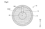
- FIG. 3 is a cross-sectional view taken along the line III-III of FIG.
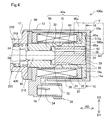
- FIG. 4 is a cross-sectional view showing a detailed configuration of the solenoid of the second embodiment.
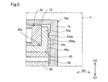
- FIG. 5 is an enlarged cross-sectional view showing the region V of FIG. 4 in an enlarged manner.
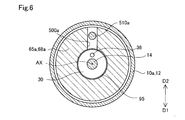
- FIG. 6 is a cross-sectional view taken along the line VI-VI of FIG.
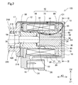
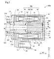
- FIG. 7 is a cross-sectional view showing a detailed configuration of the solenoid of the third embodiment.
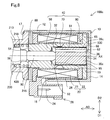
- FIG. 8 is a cross-sectional view showing a detailed configuration of the solenoid of the fourth embodiment.
- FIG. 1 schematically shows a cross section of the linear solenoid valve 300 cut along the central axis AX.
- the linear solenoid valve 300 includes a spool valve 200 and a solenoid 100 arranged side by side along the central axis AX. Note that FIGS. 1 and 2 show the solenoid 100 and the linear solenoid valve 300 in the non-energized state.
- the linear solenoid valve 300 of the present embodiment is a normally closed type, but may be a normally open type.
- the spool valve 200 shown in FIG. 1 adjusts the opening areas of a plurality of oil ports 214, which will be described later.
- the spool valve 200 includes a sleeve 210, a spool 220, a spring 230, and a spring load adjusting unit 240.
- the sleeve 210 has a substantially cylindrical external shape.
- the sleeve 210 is formed with an insertion hole 212 penetrating along the central axis AX and a plurality of oil ports 214 communicating with the insertion hole 212 and opening in the radial direction.
- a spool 220 is inserted into the insertion hole 212.
- the end of the insertion hole 212 on the solenoid 100 side is formed with an enlarged diameter and functions as an elastic member accommodating portion 218.
- the elastic member 420 which will be described later, is accommodated in the elastic member accommodating portion 218.
- the plurality of oil ports 214 are formed side by side along a direction parallel to the central axis AX (hereinafter, also referred to as "axial direction AD").
- the plurality of oil ports 214 are, for example, an input port that communicates with an oil pump (not shown) to receive an oil supply, an output port that communicates with a clutch piston (not shown), etc. It functions as a feedback port that applies a load to the vehicle, a drain port that discharges hydraulic oil, and so on.
- a collar portion 216 is formed at the end of the sleeve 210 on the solenoid 100 side.
- the flange portion 216 has a diameter increasing outward in the radial direction, and is fixed to each other with the yoke 10 of the solenoid 100 described later.
- the radial direction means a direction orthogonal to the axial direction AD.
- the spool 220 has a substantially rod-like external shape in which a plurality of large-diameter portions 222 and small-diameter portions 224 are arranged side by side along the axial direction AD.
- the spool 220 slides along the axial direction AD inside the insertion hole 212, and opens a plurality of oil ports 214 according to the positions of the large diameter portion 222 and the small diameter portion 224 along the axial direction AD. adjust.
- a shaft 90 for transmitting the thrust of the solenoid 100 to the spool 220 is in contact with the end of the spool 220 on the solenoid 100 side.
- a spring 230 is arranged at the other end of the spool 220.
- the spring 230 is composed of a compression coil spring, and presses the spool 220 in the axial direction AD to urge the spool 220 toward the solenoid 100.
- the spring load adjusting unit 240 is arranged in contact with the spring 230, and the amount of screwing into the sleeve 210 is adjusted to adjust the spring load of the spring 230.
- the solenoid 100 shown in FIGS. 1 and 2 is energized and controlled by an electronic control device (not shown) to drive the spool valve 200.
- the solenoid 100 includes a yoke 10, a coil portion 20, a plunger 30, a stator core 40, a ring member 80, and an elastic member 420.
- the yoke 10 is formed of a magnetic metal and constitutes the outer shell of the solenoid 100.
- the yoke 10 has a bottomed tubular appearance shape, and accommodates the coil portion 20, the plunger 30, and the stator core 40.
- the yoke 10 has a side surface portion 12, a bottom portion 14, an opening portion 17, and a notch portion 18.
- the side surface portion 12 has a substantially cylindrical appearance shape along the axial direction AD, and is arranged outside the coil portion 20 in the radial direction.
- the bottom portion 14 is connected to the end portion of the side surface portion 12 opposite to the spool valve 200 side and is formed perpendicular to the axial direction AD, and closes the end portion of the side surface portion 12.
- the bottom portion 14 is not limited to being perpendicular to the axial direction AD, but may be formed substantially perpendicular to the axial direction AD, or may be formed so as to intersect the axial direction AD according to the shape of the magnetic flux delivery portion 65 described later.
- the bottom portion 14 faces the proximal end surface 34 of the plunger 30, which will be described later. A detailed description of the bottom 14 will be given later.
- the space surrounded by the bottom portion 14, the stator core 40, and the shaft 90 is also referred to as a “plunger chamber 95”.
- the plunger 30 is housed in the plunger room 95.
- the opening 17 is formed at the end of the side surface 12 on the spool valve 200 side.
- the opening 17 is caulked and fixed to the flange portion 216 of the spool valve 200 after the components of the solenoid 100 are assembled inside the yoke 10.
- the spool valve 200 and the yoke 10 may be fixed by any method such as welding.
- the notch 18 is formed by notching a part of the opening 17 in the circumferential direction.
- the notch 18 of the present embodiment is formed so as to be in the ground direction D1 in the circumferential direction in a state where the solenoid 100 is assembled (hereinafter, also referred to as an “assembled state”). More specifically, it is formed so as to be in the vertical downward direction, but it is not limited to the vertical downward direction, but is less than 90 ° with respect to the vertical downward direction, such as an angle rotated by 45 ° with respect to the vertical downward direction. It may be formed at a position rotated by an angle.
- the notch 18 exposes the connector 26, which will be described later, from the yoke 10.
- the notch portion 18 functions as an inflow portion for flowing a fluid existing in the mounting environment of the solenoid 100 from the outside of the solenoid 100 into the inside of the solenoid 100.
- the fluid existing in the mounting environment of the solenoid 100 corresponds to a fluid such as hydraulic oil or air.
- the fluid that has flowed into the solenoid 100 through the notch 18 flows out to the outside of the solenoid 100 through the notch 18.
- the coil portion 20 is arranged inside the side surface portion 12 of the yoke 10 in the radial direction.
- the coil portion 20 generates a magnetic force when energized, and a loop-shaped magnetic flux flows through the side surface portion 12 of the yoke 10, the bottom portion 14 of the yoke 10, the stator core 40, the plunger 30, and the ring member 80. (Hereinafter, also referred to as "magnetic circuit") is formed.
- the coil portion 20 is not energized and the magnetic circuit is not formed. However, for convenience of explanation, the magnetic circuit formed when the coil portion 20 is energized is executed.
- a part of C1 is schematically shown by a thick arrow in FIG.
- the coil portion 20 has a coil 21 and a bobbin 22.
- the coil 21 is formed of a conducting wire having an insulating coating.
- the bobbin 22 is made of resin, and the coil 21 is wound around it.
- the bobbin 22 is connected to a connector 26 arranged on the outer peripheral portion of the yoke 10.
- the connector 26 is exposed from the yoke 10 via the notch 18.
- a connection terminal 24 to which the end of the coil 21 is connected is arranged inside the connector 26, .
- the connector 26 electrically connects the solenoid 100 and the electronic control device via a connection line (not shown).
- the outer diameter of the coil portion 20 is formed to be smaller than the inner diameter of the side surface portion 12 of the yoke 10. With such a configuration, a radial gap is formed over the entire circumference between the inner surface of the side surface portion 12 and the outer surface of the coil portion 20, and the radial outside of the magnetic flux delivery portion 65, which will be described later. It functions as a respiratory passage 28 that communicates with the outside of the solenoid 100.
- the breathing path 28 communicates with the outside of the solenoid 100 through the notch 18 of the yoke 10 to circulate the fluid existing in the mounting environment of the solenoid 100.
- the notch 18 when the notch 18 is immersed in the hydraulic oil, the hydraulic oil as a fluid is circulated, and the notch 18 is located vertically above the storage level of the hydraulic oil. Circulates air as a fluid.
- the plunger 30 is housed in the plunger room 95.
- the plunger 30 has a substantially columnar appearance shape and is made of a magnetic metal.
- the plunger 30 slides on the inner peripheral surface of the core portion 61 of the stator core 40, which will be described later, in the axial direction AD.
- the shaft 90 described above is in contact with the end surface (hereinafter, also referred to as “tip surface 32”) of the plunger 30 on the spool valve 200 side.
- tip surface 32 the end surface of the plunger 30 on the spool valve 200 side.
- the end surface of the plunger 30 opposite to the front end surface 32 faces the bottom portion 14 of the yoke 10.
- the plunger 30 is formed with a breathing hole 36 penetrating in the axial direction AD.
- the breathing hole 36 allows fluids located on the proximal end surface 34 side and the distal end surface 32 side of the plunger 30 to flow in the plunger chamber 95.
- the stator core 40 is made of a magnetic metal and is arranged between the coil portion 20 and the plunger 30.
- the stator core 40 is composed of a member in which a magnetic attraction core 50, a sliding core 60, and a magnetic flux passage suppressing portion 70 are integrated.
- the magnetic attraction core 50 is arranged so as to surround the shaft 90 in the circumferential direction.
- the magnetic attraction core 50 constitutes a portion of the stator core 40 on the spool valve 200 side, and magnetically attracts the plunger 30 by the magnetic force generated by the coil portion 20.
- a stopper 52 is arranged on the surface of the magnetic attraction core 50 facing the tip surface 32 of the plunger 30.
- the stopper 52 is made of a non-magnetic material and suppresses the direct contact between the plunger 30 and the magnetic attraction core 50, and prevents the plunger 30 from being separated from the magnetic attraction core 50 by magnetic attraction.
- the sliding core 60 constitutes a portion of the stator core 40 on the bottom 14 side, and is arranged on the outer side in the radial direction of the plunger 30.
- the sliding core 60 has a core portion 61 and a magnetic flux delivery portion 65.
- the core portion 61 and the magnetic flux transfer portion 65 are integrally molded.
- the core portion 61 has a substantially cylindrical appearance shape, and is arranged between the coil portion 20 and the plunger 30 in the radial direction.
- the core portion 61 guides the movement of the plunger 30 along the axial AD.
- the plunger 30 slides directly on the inner peripheral surface of the core portion 61.
- the end of the sliding core 60 which is opposite to the magnetic attraction core 50 side (hereinafter, also referred to as “core end 62”), faces the bottom 14 and is in contact with the bottom 14.
- the magnetic flux delivery portion 65 is formed from the core end portion 62 toward the outer side in the radial direction over the entire circumference of the core end portion 62. Therefore, the magnetic flux delivery portion 65 is located between the bobbin 22 and the bottom portion 14 of the yoke 10 in the axial direction AD.
- the magnetic flux transfer unit 65 transfers the magnetic flux between the yoke 10 and the plunger 30 via the core unit 61. More specifically, the magnetic flux transfer portion 65 of the present embodiment transfers the magnetic flux between the bottom portion 14 of the yoke 10 and the plunger 30.
- the magnetic flux transfer portion 65 may transfer the magnetic flux between the side surface portion 12 of the yoke 10 and the plunger 30.
- the magnetic flux delivery portion 65 of this embodiment is integrally molded with the core portion 61.
- the magnetic flux delivery portion 65 and the core portion 61 may be integrated after being formed as separate bodies from each other.
- the core portion 61 may be press-fitted into the through hole of the magnetic flux delivery portion 65 formed in a ring shape, or may be fixed by welding or the like after the core portion 61 is inserted.
- the magnetic flux delivery portion 65 is formed with a first facing surface 68 facing the bottom 14 of the yoke 10.
- the first facing surface 68 is formed in a planar shape along the radial direction.
- the portion of the bottom portion 14 facing the first facing surface 68 is also referred to as a “second facing surface 19”.
- the second facing surface 19 is formed in a planar shape along the radial direction and is in contact with the first facing surface 68.
- a breathing groove 500 is formed on the second facing surface 19.
- FIG. 3 for convenience of explanation, the position of the first facing surface 68 of the magnetic flux delivery portion 65 is shown by a broken line.
- the breathing groove 500 communicates the inside and the outside of the magnetic flux delivery portion 65 in the radial direction. Therefore, as shown in FIG. 2, the plunger chamber 95 and the outside of the solenoid 100 are communicated with each other via the breathing groove 500 and the breathing path 28. With such a configuration, the pressure fluctuation of the plunger chamber 95 is suppressed due to the sliding of the plunger 30, and the smooth sliding of the plunger 30 is suppressed.
- the breathing groove 500 of the present embodiment has a linear groove shape formed along the radial direction. Further, the breathing groove 500 of the present embodiment is formed so as to be in the vertical direction D2 in the assembled state.
- the "heavenly direction D2" is not limited to the vertically upward direction indicated by the arrow in FIG. 3, but means a direction on the vertically upward direction side rather than the horizontal direction. Therefore, the breathing groove 500 is formed in the assembled state along the direction rotated at an angle of less than 90 ° with respect to the vertically upward direction.
- the breathing groove 500 of the present embodiment is formed at a position rotated by about 180 ° in the circumferential direction with respect to the connector 26 and the notch 18.
- the fluid such as hydraulic oil existing in the mounting environment of the solenoid 100 may contain foreign matter such as abrasion powder. Such foreign matter may enter the respiratory tract 28 through the notch 18.
- the solenoid 100 of the present embodiment is formed so that the breathing groove 500 is in the vertical direction D2 in the assembled state. Therefore, the passage path from the notch 18 located in the ground direction D1 to the foreign matter flowing into the breathing path 28 to reach the breathing groove 500 located in the top direction D2 is set to be relatively long.
- the foreign matter flowing into the respiratory tract 28 from the notch 18 located in the ground direction D1 needs to go around the respiratory tract 28 in the circumferential direction by half a circumference in order to reach the respiratory groove 500 located in the heaven direction D2. There is.
- the "maze structure” means a structure that forms a path that is more complicated and has a longer path length than a linear path.
- the magnetic flux passage suppressing portion 70 shown in FIG. 2 is formed between the magnetic attraction core 50 and the core portion 61 in the axial direction AD.
- the magnetic flux passage suppressing unit 70 suppresses the flow of magnetic flux directly between the core unit 61 and the magnetic attraction core 50.
- the magnetic flux passage suppressing portion 70 of the present embodiment is configured such that the magnetic flux passage suppressing portion 70 is formed to have a thin radial thickness of the stator core 40 so that the magnetic resistance is larger than that of the magnetic attraction core 50 and the core portion 61.
- the ring member 80 is arranged between the coil portion 20 and the flange portion 216 of the spool valve 200 in the axial direction AD.
- the ring member 80 is an end portion of the magnetic attraction core 50 of the stator core 40 described later in the axial direction AD and opposite to the plunger 30 side (hereinafter, also referred to as “magnetic attraction core end portion 54”). ) Is arranged radially outside.
- the ring member 80 has a ring-shaped external shape and is made of a magnetic metal.
- the ring member 80 transfers magnetic flux between the magnetic attraction core 50 of the stator core 40 and the side surface portion 12 of the yoke 10.
- the ring member 80 is configured to be displaceable in the radial direction.
- the manufacturing dimensional variation of the stator core 40 and the axial deviation in assembly are absorbed.
- the magnetic attraction core 50 is press-fitted into the ring member 80. Not limited to press fitting, the magnetic attraction core 50 may be fitted with a slight gap in the radial direction.
- the elastic member 420 is accommodated in the elastic member accommodating portion 218 formed in the sleeve 210 of the spool valve 200, and urges the stator core 40 toward the bottom portion 14.
- the elastic member 420 is arranged in contact with the end surface of the magnetic attraction core 50 in the axial direction AD and on the side opposite to the plunger 30 side (hereinafter, also referred to as “end surface 56”).
- the elastic member 420 is composed of a compression coil spring having a substantially cylindrical appearance shape.
- a spool 220 is inserted inside the elastic member 420 in the radial direction.
- the stator core 40 is axially urged toward the bottom 14 side of the yoke 10 by the elastic member 420, the magnetic flux delivery portion 65 is pressed against the bottom 14 and from the bottom 14 of the yoke 10 to the magnetic flux delivery portion 65. The loss of the transmitted magnetic flux is suppressed.
- the yoke 10, the ring member 80, the plunger 30, and the stator core 40 are each made of iron. Not limited to iron, it may be composed of any magnetic material such as nickel and cobalt. Further, in the present embodiment, the outer peripheral surface of the plunger 30 is plated. By such a plating treatment, the surface hardness of the plunger 30 can be increased, and deterioration of slidability can be suppressed. Further, in the present embodiment, the yoke 10 is formed by press molding and the stator core 40 is formed by forging, but each may be formed by any molding method. For example, the yoke 10 may be integrated by caulking fixing, press-fitting fixing, or the like after the side surface portion 12 and the bottom portion 14 are formed separately from each other.
- FIGS. 1 and 2 show a state in which the plunger 30 is farthest from the magnetic attraction core 50 without energizing the coil 21.
- the magnetic circuit C1 is formed inside the solenoid 100.
- the plunger 30 is attracted to the magnetic attraction core 50 side by the formation of the magnetic circuit C1 and slides on the inner peripheral surface of the core portion 61 in the axial direction AD.
- the current flowing through the coil portion 20 increases, the magnetic flux density of the magnetic circuit C1 increases, and the stroke amount of the plunger 30 increases.
- the opening area of the oil port 214 is adjusted, and the oil pressure proportional to the current value flowing through the coil 21 is output.
- the core portion 61 and the magnetic flux delivery portion 65 are integrally formed. Therefore, there is no radial gap between the core portion 61 and the magnetic flux delivery portion 65, and it is possible to prevent the core portion 61 and the magnetic flux delivery portion 65 from being eccentric. Therefore, when the magnetic circuit C1 is configured by energization, it is possible to suppress the occurrence of radial bias in the distribution of the magnetic flux transmitted from the magnetic flux delivery portion 65 to the core portion 61, and from the core portion 61 to the plunger 30. It is possible to suppress the occurrence of radial bias in the distribution of the magnetic flux transmitted to.
- the magnetic flux densities of the magnetic circuit C1 can be made substantially equal in the circumferential direction. Therefore, an increase in side force due to a bias in the distribution of magnetic flux can be suppressed, and deterioration of the slidability of the plunger 30 can be suppressed.
- the magnetic flux delivery portion 65 corresponds to the first magnetic flux delivery portion in the present disclosure
- the ring member 80 corresponds to the second magnetic flux delivery portion in the present disclosure
- the notch portion 18 corresponds to the inflow portion in the present disclosure. Corresponds to.
- the sliding core 60 has a diameter from the tubular core portion 61 arranged radially outward with respect to the plunger 30 and the core end portion 62 of the core portion 61. Since the magnetic flux delivery portion 65 is formed toward the outside in the direction and transfers the magnetic flux, there is almost no radial gap between the core portion 61 and the magnetic flux delivery portion 65. Therefore, it is possible to prevent the core portion 61 and the magnetic flux delivery portion 65 from being eccentric. Therefore, the diameter of the distribution of the magnetic flux transmitted from the magnetic flux delivery portion 65 to the plunger 30 via the core portion 61 due to such eccentricity. It is possible to suppress the occurrence of directional bias. Therefore, it is possible to suppress an increase in side force due to a bias in the distribution of magnetic flux.
- a breathing groove 500 that communicates the inside and outside of the magnetic flux delivery portion 65 in the radial direction with the second facing surface 19 facing the magnetic flux delivery portion 65 at the bottom 14 of the yoke 10 becomes the top direction D2 in the assembled state. It is formed like this. Further, the notch 18 serving as the inflow port of the foreign matter flowing into the respiratory tract 28 is formed so as to be in the ground direction D1 in the assembled state. That is, the notch 18 is formed in a direction different from that of the breathing groove 500. With such a configuration, a maze structure with a long path can be realized as the structure of the respiratory path 28.
- the solenoid 100 of the first embodiment it is possible to suppress the invasion of foreign matter into the plunger chamber 95 while suppressing the increase in the side force of the solenoid 100.
- the breathing groove 500 is formed on the second facing surface 19 of the bottom portion 14 of the yoke 10, the circumferential position of the breathing groove 500 with respect to the notch 18 which is the inflow port of the foreign matter flowing into the breathing path 28 can be determined. It can be specified only by the yoke 10. Therefore, it is possible to easily realize a configuration in which the breathing groove 500 is in the vertical direction D2 in the assembled state, and it is possible to omit the step of adjusting the position of the breathing groove 500 in the circumferential direction when the solenoid 100 is assembled.
- the solenoid 100a of the second embodiment shown in FIG. 4 is different from the solenoid 100 of the first embodiment in that the yoke 10a and the stator core 40a are provided in place of the yoke 10 and the stator core 40. More specifically, in the solenoid 100 of the first embodiment, the breathing groove 500a is formed on the first facing surface 68a of the magnetic flux delivery portion 65a instead of the breathing groove 500 formed on the second facing surface 19 of the yoke 10. Has been done. Since the other configurations are the same as those of the solenoid 100 of the first embodiment, the same configurations are designated by the same reference numerals, and detailed description thereof will be omitted.
- a breathing groove 500a is formed on the first facing surface 68a in the magnetic flux delivery portion 65a of the sliding core 60a included in the stator core 40a of the second embodiment.
- the breathing groove 500a has a linear groove shape formed along the radial direction.
- a protruding portion 510a that protrudes toward the first facing surface 68a in the axial direction AD is formed on the second facing surface 19a of the bottom portion 14a of the yoke 10a of the second embodiment.
- the protruding portion 510a is formed so as to be in the vertical direction D2 in the assembled state.
- the protrusion 510a is formed at a position rotated by about 180 ° in the circumferential direction with respect to the connector 26 and the notch 18 shown in FIG.
- the protrusion 510a has a diameter smaller than the width of the breathing groove 500a and engages with the breathing groove 500a formed on the first facing surface 68a. By such engagement, the circumferential positions of the stator core 40a and the breathing groove 500a with respect to the yoke 10a are determined.
- the same effect as that of the first embodiment is obtained.
- the protruding portion 510a that engages with the breathing groove 500a is formed on the second facing surface 19a, the circumferential position of the breathing groove 500a with respect to the yoke 10a can be fixed. Therefore, it is possible to omit adjusting the circumferential position of the sliding core 60a when assembling the solenoid 100a, and it is possible to easily realize a configuration in which the breathing groove 500a is in the vertical direction D2 in the assembled state.
- the solenoid 100b of the third embodiment shown in FIG. 7 is different from the solenoid 100 of the first embodiment in that it includes a stator core 40b having a magnetic flux passage suppressing portion 70b instead of the magnetic flux passing suppressing portion 70. Since the other configurations are the same as those of the solenoid 100 of the first embodiment, the same configurations are designated by the same reference numerals, and detailed description thereof will be omitted.
- the magnetic flux passage suppressing portion 70b in the solenoid 100b of the third embodiment includes a connecting portion 72b formed of a non-magnetic material.
- the connecting portion 72b physically connects the magnetic attraction core 50 and the sliding core 60, which are formed as separate bodies from each other.
- the connecting portion 72b has a wall thickness substantially equal to that of the core portion 61, and is formed by brazing or the like.
- the connecting portion 72b is formed of austenitic stainless steel, but is not limited to austenitic stainless steel, and may be formed of any non-magnetic material such as aluminum or brass.
- the magnetic flux passage suppressing portion 70b includes the connecting portion 72b formed of a non-magnetic material, the magnetic flux is directly transmitted from the core portion 61 to the magnetic attraction core 50 without passing through the plunger 30 when energized. It is possible to further suppress the passage. Further, since the connecting portion 72b is formed to have a wall thickness substantially equal to that of the core portion 61, the magnetic attraction core 50 and the core portion 61 can be more firmly connected, and the plunger 30 also slides on the connecting portion 72b. Can guide you.
- the solenoid 100c of the fourth embodiment shown in FIG. 8 is different from the solenoid 100 of the first embodiment in that the plunger 30c is provided in place of the plunger 30. Since the other configurations are the same as those of the solenoid 100 of the first embodiment, the same configurations are designated by the same reference numerals, and detailed description thereof will be omitted.
- the plating treatment of the outer peripheral surface is omitted, and the outer peripheral surface is covered with the film member 39c.
- the film member 39c is formed of a Teflon sheet (Teflon is a registered trademark) and is wound around a plunger 30c. Not limited to Teflon, it may be formed of any other non-magnetic material.
- the film member 39c of the present embodiment covers the plunger 30c on the outer peripheral surface of the plunger 30c, that is, the outer surface in the radial direction, over the entire length of the axial AD of the plunger 30c.
- the total length of the axial AD of the plunger 30c is not limited, and at least a part of the outer peripheral surface of the plunger 30c including the sliding portion of the plunger 30c may be covered.
- the same effect as that of the first embodiment is obtained.
- the film member 39c formed of a non-magnetic material and covering at least a part of the outer peripheral surface of the plunger 30c is further provided, the plating treatment of the outer peripheral surface of the plunger 30c can be omitted, and the cost required for manufacturing the plunger 30c is increased. Can be suppressed.
- breathing grooves 500 and 500a in each of the above embodiments are merely examples and can be changed in various ways.
- the breathing grooves 500 and 500a are not limited to a linear groove shape along the radial direction, and may have an arbitrary groove shape such as a curved shape or a wavy shape, and are not limited to one and have two or more. Any number of grooves may be formed side by side in the circumferential direction.
- breathing grooves 500 and 500a may be formed on both the first facing surfaces 68 and 68a of the magnetic flux delivery portions 65 and 65a and the second facing surfaces 19 and 19a of the bottoms 14 and 14a, respectively.
- the breathing grooves 500 and 500a that communicate the inner and outer sides of the first magnetic flux delivery portion in the radial direction with at least one of the first facing surfaces 68 and 68a and the second facing surfaces 19 and 19a are solenoids. It may be formed so as to be in the heaven direction D2 in a state where 100, 100a to 100c are assembled. Even with such a configuration, the same effect as that of each of the above-described embodiments can be obtained.
- the protruding portion 510a is formed on the second facing surface 19a, but the protruding portion 510a may be omitted.
- the breathing groove 500a can be directed to the top direction D2 by adjusting the circumferential position of the sliding core 60a when assembling the solenoid 100a.
- any radial through hole formed in the side surface 12 of the yokes 10 and 10a exists in the mounting environment of the solenoids 100, 100a-c. It may function as an inflow part of the fluid.
- the core portions 61 of the sliding cores 60 and 60a and the magnetic flux delivery portions 65 and 65a may be formed separately from each other. In such an embodiment, the core portion 61 may be press-fitted into the inner holes of the magnetic flux delivery portions 65, 65a formed in an annular shape.
- the elastic member 420 is not limited to the compression coil spring, and may be composed of any elastic member such as a disc spring or a leaf spring.
- the elastic member accommodating portion 218, the elastic member 420 may be formed with the coil portion 20 in the axial direction AD.
- the magnetic flux delivery portions 65 and 65a may be urged by being arranged between the magnetic flux delivery portions 65 and 65a. Even with such a configuration, the same effect as that of each of the above-described embodiments can be obtained.
- the connecting portion 72b is formed to have a wall thickness substantially equal to that of the core portion 61, but is formed to be thinner than the core portion 61 and is formed on the inner peripheral surface of the coil portion 20.
- the magnetic attraction core 50 and the sliding cores 60 and 60a may be physically connected on the side or the like. Even with such a configuration, the same effect as that of the third embodiment can be obtained.
- the sheet-shaped film member 39c is wound around the plunger 30c, but the film member 39c is formed not only by winding the sheet but also by coating the outer peripheral surface of the plunger 30c. It may have been done. Further, by coating the inner peripheral surfaces of the sliding cores 60 and 60a with a non-magnetic material, at least a part of the outer peripheral surface of the plunger 30c may be covered with the film member 39c. Even with such a configuration, the same effect as that of the fourth embodiment can be obtained.
- the solenoids 100, 100a to 100c of each of the above embodiments are assembled and used so that the positions of the connector 26 and the notch 18 in the circumferential direction are in the ground direction D1, but the solenoids are not limited to the ground direction D1. It may be assembled and used so as to be in an arbitrary direction, and the notch portion 18 may be formed in a direction different from that of the breathing grooves 500 and 500a. Even with this configuration, foreign matter that has flowed into the yokes 10 and 10a from the outside of the solenoids 100 and 100a to 100a through the notch 18 passes through a relatively long path to reach the breathing grooves 500 and 500a. , The invasion of foreign matter into the plunger chamber 95 can be suppressed.
- the position of the notch 18 in the circumferential direction may be formed in the vertical direction D2, or may be formed in the same direction as the breathing grooves 500 and 500a.
- a foreign substance contained in a fluid such as air falls vertically downward according to gravity and passes through a long path in order to reach the breathing grooves 500 and 500a located in the heavenly direction D2. Therefore, it is possible to suppress the invasion of foreign matter into the plunger chamber 95.
- the solenoids 100, 100a to 100c of each of the above embodiments are applied to the linear solenoid valve 300 for controlling the hydraulic pressure of the hydraulic oil supplied to the automatic transmission for vehicles, and function as an actuator for driving the spool valve 200.
- the present disclosure is not limited to this.
- it is not limited to being mounted on a valve body provided on the outer surface of a transmission case, and may be mounted on any hydraulic device that requires control of flood control.
- an arbitrary valve such as a poppet valve may be driven, and instead of the valve, an arbitrary driven body such as a switch may be driven.
- the present disclosure is not limited to each of the above-described embodiments, and can be realized with various configurations within a range that does not deviate from the purpose.
- the technical features in each embodiment corresponding to the technical features in the embodiments described in the column of the outline of the invention may be used to solve some or all of the above-mentioned problems, or one of the above-mentioned effects. It is possible to replace or combine as appropriate to achieve a part or all. Further, if the technical feature is not described as essential in the present specification, it can be appropriately deleted.
Abstract
ソレノイド(100、100a~c)は、コイル部(20)と、側面部(12)と底部(14、14a)とを有するヨーク(10、10a)と、プランジャ(30、30c)と、ステータコア(40、40a~b)であって、磁気吸引コア(50)と、筒状のコア部(61)とコア端部(62)から径方向の外側に向かって形成されヨークとコア部との間における磁束の受け渡しを行なう第1磁束受渡部(65、65a)と、を有する摺動コア(60、60a)とを有するステータコアとを備え、第1磁束受渡部において底部と対向する第1対向面(68、68a)と、底部において第1磁束受渡部と対向する第2対向面(19、19a)とのうちの少なくとも一方には、第1磁束受渡部の径方向の内側と外側を連通させる呼吸溝(500、500a)が、ソレノイドが組み付けられた状態において天方向(D2)となるように形成されている。
Description
本出願は、2019年7月18日に出願された日本出願番号2019-132578号に基づくもので、ここにその記載内容を援用する。
本開示は、ソレノイドに関する。
従来から、通電により磁力を発生するコイルの内側において、ステータコアの内側をプランジャが摺動するソレノイドが知られている。特許文献1に記載のソレノイドでは、ステータコアの外周に磁性体のリングコアが配置されている。これにより、ヨーク等の磁気回路部品とステータコアとをリングコアを介して磁気結合させ、磁気回路部品とステータコアとの間の組付隙間に起因する磁力低下を抑制している。
特許文献1に記載のソレノイドでは、リングコアが径方向に移動可能に構成されているため、摺動コアに対してリングコアが偏心して組み付けられると、摺動コアとリングコアとの間の隙間の大きさに径方向の偏りが発生するおそれがある。これにより、リングコアを通って摺動コアとプランジャとに伝達される磁束の分布に径方向の偏りが発生し、径方向への吸引力がサイドフォースとして発生するおそれがある。サイドフォースが増大すると、プランジャの摺動性が悪化するおそれがある。また、プランジャ室に異物が入り込んだ場合にもプランジャの摺動性が悪化するおそれがある。このため、サイドフォースの増大を抑制しつつ、プランジャ室への異物の侵入を抑制できる技術が望まれる。
本開示は、以下の形態として実現することが可能である。
本開示の一形態によれば、ソレノイドが提供される。このソレノイドは、通電により磁力を発生するコイル部と、軸方向に沿った側面部と、前記軸方向と交差する方向に沿って形成された底部と、を有し、前記コイル部を収容するヨークと、前記軸方向に摺動する柱状のプランジャと、ステータコアであって、前記軸方向において前記プランジャの先端面と対向して配置されて前記コイル部が発生する磁力により前記プランジャを磁気吸引する磁気吸引コアと、前記軸方向と直交する径方向において前記コイル部の内側に配置されて前記プランジャを収容する筒状のコア部と、前記コア部の前記軸方向の端部であって前記底部と対向するコア端部から前記径方向の外側に向かって形成され、前記ヨークと前記コア部との間における磁束の受け渡しを行なう第1磁束受渡部と、を有する摺動コアと、前記摺動コアと前記磁気吸引コアとの間における磁束の通過を抑制する磁束通過抑制部と、を有するステータコアと、前記磁気吸引コアの前記軸方向の端部であって前記先端面と対向する側とは反対側の磁気吸引コア端部の前記径方向の外側に配置され、前記磁気吸引コアと前記側面部との間における磁束の受け渡しを行なう第2磁束受渡部と、を備え、前記第1磁束受渡部において前記底部と対向する第1対向面と、前記底部において前記第1磁束受渡部と対向する第2対向面とのうちの少なくとも一方には、前記第1磁束受渡部の前記径方向の内側と外側を連通させる呼吸溝が、前記ソレノイドが組み付けられた状態において天方向となるように形成されている。
この形態のソレノイドによれば、摺動コアが、プランジャに対して径方向外側に配置された筒状のコア部と、コア部のコア端部から径方向外側に向かって形成されて磁束の受け渡しを行なう第1磁束受渡部とを有するので、コア部と第1磁束受渡部との間に径方向の隙間がほぼ存在しない。このため、コア部と第1磁束受渡部とが偏心することを抑制できるので、かかる偏心に起因してコア部を介して第1磁束受渡部からプランジャへと伝達される磁束の分布に径方向の偏りが発生することを抑制できる。したがって、磁束の分布の偏りによるサイドフォースの増大を抑制できる。加えて、第1磁束受渡部においてヨークの底部と対向する第1対向面と、底部において第1磁束受渡部と対向する第2対向面とのうちの少なくとも一方に、第1磁束受渡部の径方向の内側と外側を連通させる呼吸溝が、ソレノイドが組み付けられた状態において天方向となるように形成されている。このため、ソレノイドの外部からソレノイドの内部へと流入した異物は、呼吸溝に到達するために比較的長い経路を通過する。例えば、ソレノイドの搭載環境に存在する流体をソレノイドの内部へと流入させる流入部が、ソレノイドが組み付けられた状態において天方向とは異なる方向となるように形成されている場合には、天方向とは異なる方向から流入した異物が天方向に形成された呼吸溝に到達するために比較的長い経路を通過する。また、例えば、かかる流入部が、ソレノイドが組み付けられた状態において天方向となるように形成されている場合においても、異物は重力に従って鉛直下方へと向かう傾向を有するため、天方向に形成された呼吸溝に到達するために長い経路を通過する。このように、異物の通過経路として長い経路の迷路構造を実現できるので、プランジャが収容されるプランジャ室へと異物が侵入することを抑制でき、プランジャの摺動性が悪化することを抑制できる。したがって、サイドフォースの増大を抑制しつつ、プランジャ室への異物の侵入を抑制できる。
本開示は、種々の形態で実現することも可能である。例えば、ソレノイドバルブ、ソレノイドの製造方法等の形態で実現することができる。
本開示についての上記目的およびその他の目的、特徴や利点は、添付の図面を参照しながら下記の詳細な記述により、より明確になる。その図面は、
図1は、第1実施形態のソレノイドが適用されたリニアソレノイドバルブの概略構成を示す断面図であり、
図2は、ソレノイドの詳細構成を示す断面図であり、
図3は、図2のIII-III線に沿った断面図であり、
図4は、第2実施形態のソレノイドの詳細構成を示す断面図であり、
図5は、図4の領域Vを拡大して示す拡大断面図であり、
図6は、図4のVI-VI線に沿った断面図であり、
図7は、第3実施形態のソレノイドの詳細構成を示す断面図であり、
図8は、第4実施形態のソレノイドの詳細構成を示す断面図である。
A.第1実施形態
A-1.構成
図1に示す第1実施形態のソレノイド100は、リニアソレノイドバルブ300に適用され、スプール弁200を駆動させるアクチュエータとして機能する。リニアソレノイドバルブ300は、図示しない車両用自動変速機に供給する作動油の油圧を制御するために用いられ、図示しないトランスミッションケースの外側面に設けられたバルブボディに搭載されている。本実施形態のリニアソレノイドバルブ300は、後述するコネクタ26の周方向の位置が地方向D1となるようにバルブボディに組み付けられて用いられている。本実施形態において、「地方向D1」とは、図1において矢印で示す鉛直下方向に限らず、水平方向よりも鉛直下方向側の方向を意味している。コネクタ26の周方向の位置は、リニアソレノイドバルブ300の搭載条件に応じて定められている。なお、図1では、中心軸AXに沿ってリニアソレノイドバルブ300を切断した断面を模式的に示している。
リニアソレノイドバルブ300は、中心軸AXに沿って互いに並んで配置されたスプール弁200とソレノイド100とを備える。なお、図1および図2では、非通電状態のソレノイド100およびリニアソレノイドバルブ300を示している。本実施形態のリニアソレノイドバルブ300は、ノーマリクローズタイプであるが、ノーマリオープンタイプであってもよい。
図1に示すスプール弁200は、後述する複数のオイルポート214の開口面積を調整する。スプール弁200は、スリーブ210と、スプール220と、バネ230と、バネ荷重調整部240とを備える。
スリーブ210は、略円筒状の外観形状を有する。スリーブ210には、中心軸AXに沿って貫通する挿入孔212と、挿入孔212と連通して径方向に開口する複数のオイルポート214とが形成されている。挿入孔212には、スプール220が挿入されている。挿入孔212のソレノイド100側の端部は、拡径して形成され、弾性部材収容部218として機能する。弾性部材収容部218には、後述する弾性部材420が収容される。複数のオイルポート214は、中心軸AXと平行な方向(以下、「軸方向AD」とも呼ぶ)に沿って互いに並んで形成されている。複数のオイルポート214は、例えば、図示しないオイルポンプと連通して油圧の供給を受ける入力ポート、図示しないクラッチピストン等と連通して油圧を供給する出力ポート、出力される油圧に応じてスプール220に負荷荷重を付与するフィードバックポート、作動油を排出するドレインポート等として機能する。スリーブ210のソレノイド100側の端部には、鍔部216が形成されている。鍔部216は、径方向外側に向かって拡径しており、後述するソレノイド100のヨーク10と互いに固定される。なお、本実施形態において、径方向とは、軸方向ADに直交する方向を意味している。
スプール220は、軸方向ADに沿って複数の大径部222と小径部224とが並んで配置された略棒状の外観形状を有する。スプール220は、挿入孔212の内部において軸方向ADに沿って摺動し、大径部222と小径部224との軸方向ADに沿った位置に応じて、複数のオイルポート214の開口面積を調整する。スプール220のソレノイド100側の端部には、ソレノイド100の推力をスプール220に伝達するためのシャフト90が当接して配置されている。スプール220の他端には、バネ230が配置されている。バネ230は、圧縮コイルスプリングにより構成され、スプール220を軸方向ADに押圧してソレノイド100側へと付勢している。バネ荷重調整部240は、バネ230と当接して配置され、スリーブ210に対するねじ込み量が調整されることにより、バネ230のバネ荷重を調整する。
図1および図2に示すソレノイド100は、図示しない電子制御装置によって通電制御されて、スプール弁200を駆動する。ソレノイド100は、ヨーク10と、コイル部20と、プランジャ30と、ステータコア40と、リング部材80と、弾性部材420とを備える。
図2に示すように、ヨーク10は、磁性体の金属により形成され、ソレノイド100の外郭を構成している。ヨーク10は、有底筒状の外観形状を有し、コイル部20とプランジャ30とステータコア40とを収容する。ヨーク10は、側面部12と、底部14と、開口部17と、切欠部18とを有する。
側面部12は、軸方向ADに沿った略円筒状の外観形状を有し、コイル部20の径方向外側に配置されている。
底部14は、側面部12のスプール弁200側とは反対側の端部に連なって軸方向ADと垂直に形成され、側面部12の端部を閉塞している。なお、底部14は、軸方向ADと垂直に限らず、略垂直に形成されてもよく、後述する磁束受渡部65の形状に応じて軸方向ADと交差して形成されてもよい。底部14は、後述するプランジャ30の基端面34と対向している。底部14についての詳細な説明は、後述する。以下の説明では、底部14とステータコア40とシャフト90とにより囲まれる空間を「プランジャ室95」とも呼ぶ。プランジャ室95には、プランジャ30が収容されている。
開口部17は、側面部12のスプール弁200側の端部に形成されている。開口部17は、ヨーク10の内部にソレノイド100の構成部品が組み付けられた後、スプール弁200の鍔部216とかしめ固定される。なお、かしめ固定に代えて、溶接等の任意の方法を用いてスプール弁200とヨーク10とが固定されてもよい。
切欠部18は、開口部17の周方向の一部が切り欠かれて形成されている。本実施形態の切欠部18は、ソレノイド100が組み付けられた状態(以下、「組み付け状態」とも呼ぶ)において、周方向のうち地方向D1となるように形成されている。より具体的には、鉛直下方向となるように形成されているが、鉛直下方向に限らず、鉛直下方向に対して45°回転させた角度等、鉛直下方向に対して90°未満の角度で回転させた位置に形成されていてもよい。切欠部18によって、後述するコネクタ26がヨーク10から露出している。また、切欠部18は、ソレノイド100の搭載環境に存在する流体を、ソレノイド100の外部からソレノイド100の内部へと流入させる流入部として機能する。ソレノイド100の搭載環境に存在する流体には、作動油や空気等の流体が該当する。なお、切欠部18を介してソレノイド100の内部へと流入した流体は、切欠部18を介してソレノイド100の外部へと流出する。
コイル部20は、ヨーク10の側面部12の径方向内側に配置されている。コイル部20は、通電されることにより磁力を発生し、ヨーク10の側面部12と、ヨーク10の底部14と、ステータコア40と、プランジャ30と、リング部材80とを通るループ状の磁束の流れ(以下、「磁気回路」とも呼ぶ)を形成させる。図1および図2に示す状態では、コイル部20への通電が実行されず磁気回路が形成されていないが、説明の便宜上、コイル部20への通電が実行された場合に形成される磁気回路C1の一部を、図2において太線の矢印で模式的に示している。
コイル部20は、コイル21とボビン22とを有する。コイル21は、絶縁被覆が施された導線により形成されている。ボビン22は、樹脂により形成され、コイル21が巻回されている。ボビン22は、ヨーク10の外周部に配置されたコネクタ26と連結されている。コネクタ26は、切欠部18を介してヨーク10から露出している。コネクタ26の内部には、コイル21の端部が接続された接続端子24が配置されている。コネクタ26は、図示しない接続線を介してソレノイド100と電子制御装置との電気的な接続を行なう。
コイル部20の外径は、ヨーク10の側面部12の内径よりも小さく形成されている。このような構成により、側面部12の内側面とコイル部20の外側面との間には、全周に亘って径方向の隙間が形成されており、後述する磁束受渡部65の径方向外側とソレノイド100の外部を連通させる呼吸路28として機能する。呼吸路28は、ヨーク10の切欠部18を介してソレノイド100の外部と連通し、ソレノイド100の搭載環境に存在する流体を流通させる。例えば、ソレノイド100の搭載環境として、切欠部18が作動油に浸かっている場合には、流体としての作動油を流通させ、切欠部18が作動油の貯留レベルよりも鉛直上方に位置する場合には、流体としての空気を流通させる。
プランジャ30は、プランジャ室95に収容されている。プランジャ30は、略円柱状の外観形状を有し、磁性体の金属により構成されている。プランジャ30は、後述するステータコア40のコア部61の内周面を軸方向ADに摺動する。プランジャ30のスプール弁200側の端面(以下、「先端面32」とも呼ぶ)には、上述したシャフト90が当接して配置されている。これにより、プランジャ30は、図1に示すスプール220に伝達されるバネ230の付勢力により、軸方向ADに沿ってヨーク10の底部14側へと付勢されている。図2に示すように、プランジャ30の先端面32とは反対側の端面(以下、「基端面34」とも呼ぶ)は、ヨーク10の底部14と対向している。プランジャ30には、軸方向ADに貫通する呼吸孔36が形成されている。呼吸孔36は、プランジャ室95において、プランジャ30の基端面34側および先端面32側に位置する流体を流通させる。
ステータコア40は、磁性体の金属により構成され、コイル部20とプランジャ30との間に配置されている。ステータコア40は、磁気吸引コア50と、摺動コア60と、磁束通過抑制部70とが一体化された部材により構成されている。
磁気吸引コア50は、シャフト90を周方向に取り囲んで配置されている。磁気吸引コア50は、ステータコア40のうちスプール弁200側の部分を構成し、コイル部20が発生する磁力によりプランジャ30を磁気吸引する。磁気吸引コア50のうちプランジャ30の先端面32と対向する面には、ストッパ52が配置されている。ストッパ52は、非磁性体により構成され、プランジャ30と磁気吸引コア50とが直接当接することを抑制し、磁気吸引により磁気吸引コア50からプランジャ30が離れなくなることを抑制する。
摺動コア60は、ステータコア40のうち底部14側の部分を構成し、プランジャ30の径方向外側に配置されている。摺動コア60は、コア部61と、磁束受渡部65とを有する。本実施形態において、コア部61と磁束受渡部65とは、一体に成形されている。
コア部61は、略円筒状の外観形状を有し、径方向においてコイル部20とプランジャ30との間に配置されている。コア部61は、プランジャ30の軸方向ADに沿った移動をガイドする。これにより、プランジャ30は、コア部61の内周面を直接摺動する。コア部61とプランジャ30との間には、プランジャ30の摺動性を確保するための図示しない摺動ギャップが存在している。摺動コア60の端部であって磁気吸引コア50側とは反対側の端部(以下、「コア端部62」とも呼ぶ)は、底部14と対向して当接している。
磁束受渡部65は、コア端部62の全周に亘って、コア端部62から径方向外側に向かって形成されている。このため、磁束受渡部65は、軸方向ADにおいて、ボビン22とヨーク10の底部14との間に位置している。磁束受渡部65は、コア部61を介してヨーク10とプランジャ30との間における磁束の受け渡しを行なう。より具体的には、本実施形態の磁束受渡部65は、ヨーク10の底部14とプランジャ30との間における磁束の受け渡しを行なう。なお、磁束受渡部65は、ヨーク10の側面部12とプランジャ30との間における磁束の受け渡しを行なってもよい。本実施形態の磁束受渡部65は、コア部61と一体に成形されている。なお、磁束受渡部65とコア部61とは、互いに別体として形成された後に一体化されてもよい。例えば、リング状に形成された磁束受渡部65の貫通孔に、コア部61が圧入されてもよく、コア部61が挿入された後に溶接等により固定されてもよい。
磁束受渡部65には、ヨーク10の底部14と対向する第1対向面68が形成されている。本実施形態において、第1対向面68は、径方向に沿って平面状に形成されている。また、以下の説明では、底部14において第1対向面68と対向する部分を、「第2対向面19」とも呼ぶ。第2対向面19は、径方向に沿って平面状に形成されて第1対向面68と当接している。第2対向面19には、呼吸溝500が形成されている。
図3では、説明の便宜上、磁束受渡部65の第1対向面68の位置を、破線で示している。図3に示すように、呼吸溝500は、磁束受渡部65の径方向の内側と外側を連通させる。したがって、図2に示すように、呼吸溝500と呼吸路28とを介して、プランジャ室95とソレノイド100の外部が連通されている。このような構成により、プランジャ30の摺動に伴ってプランジャ室95の圧力が変動することが抑制され、プランジャ30の滑らかな摺動が阻害されることが抑制される。
図3に示すように、本実施形態の呼吸溝500は、径方向に沿って形成された直線状の溝形状を有する。また、本実施形態の呼吸溝500は、組み付け状態において天方向D2となるように形成されている。本実施形態において、「天方向D2」とは、図3において矢印で示す鉛直上方向に限らず、水平方向よりも鉛直上方向側の方向を意味している。このため、呼吸溝500は、組み付け状態において、鉛直上方向に対して90°未満の角度で回転させた方向に沿って形成されている。図2に示すように、本実施形態の呼吸溝500は、コネクタ26および切欠部18に対して周方向に約180°回転させた位置に形成されている。
ソレノイド100の搭載環境に存在する作動油等の流体には、摩耗粉等の異物が含まれていることがある。かかる異物は、切欠部18を通って呼吸路28へと侵入するおそれがある。本実施形態のソレノイド100は、組み付け状態において呼吸溝500が天方向D2となるように形成されている。このため、地方向D1に位置する切欠部18から呼吸路28へと流入した異物が、天方向D2に位置する呼吸溝500に到達するまでの通過経路が比較的長く設定されている。本実施形態において、地方向D1に位置する切欠部18から呼吸路28へと流入した異物は、天方向D2に位置する呼吸溝500に到達するために周方向において呼吸路28を半周分回り込む必要がある。このように、異物が通過する経路がいわゆる迷路構造を有するので、呼吸路28へと流入した異物がプランジャ室95へと侵入することが抑制されている。本実施形態において、「迷路構造」とは、直線状の経路に比べて複雑であり経路長が長い経路を形成する構造を意味している。
図2に示す磁束通過抑制部70は、軸方向ADにおいて、磁気吸引コア50とコア部61との間に形成されている。磁束通過抑制部70は、コア部61と磁気吸引コア50との間で直接的に磁束が流れることを抑制する。本実施形態の磁束通過抑制部70は、ステータコア40の径方向の厚みが薄肉に形成されることにより、磁気吸引コア50およびコア部61よりも磁気抵抗が大きくなるように構成されている。
リング部材80は、軸方向ADにおいてコイル部20とスプール弁200の鍔部216との間に配置されている。換言すると、リング部材80は、後述するステータコア40の磁気吸引コア50における軸方向ADの端部であってプランジャ30側とは反対側の端部(以下、「磁気吸引コア端部54」とも呼ぶ)の径方向外側に配置されている。リング部材80は、リング状の外観形状を有し、磁性体の金属により構成されている。リング部材80は、ステータコア40の磁気吸引コア50とヨーク10の側面部12との間における磁束の受け渡しを行なう。リング部材80は、径方向において変位可能に構成されている。これにより、ステータコア40の製造上の寸法ばらつきと組み付け上の軸ずれとが吸収される。本実施形態において、リング部材80には、磁気吸引コア50が圧入されている。なお、圧入に限らず、径方向の僅かな隙間を設けて磁気吸引コア50が嵌合されていてもよい。
弾性部材420は、スプール弁200のスリーブ210に形成された弾性部材収容部218に収容され、ステータコア40を底部14側へと付勢する。弾性部材420は、磁気吸引コア50における軸方向ADの端面であってプランジャ30側とは反対側の端面(以下、「端面56」とも呼ぶ)と当接して配置されている。本実施形態において、弾性部材420は、略円筒状の外観形状を有する圧縮コイルバネにより構成されている。弾性部材420の径方向内側には、スプール220が挿入されている。弾性部材420により、ステータコア40がヨーク10の底部14側へと軸方向ADに付勢されるので、磁束受渡部65が底部14へと圧接され、ヨーク10の底部14から磁束受渡部65へと伝達される磁束の損失が抑制される。
本実施形態において、ヨーク10と、リング部材80と、プランジャ30と、ステータコア40とは、それぞれ鉄により構成されている。なお、鉄に限らず、ニッケルやコバルト等、任意の磁性体により構成されてもよい。また、本実施形態において、プランジャ30の外周面には、めっき処理が施されている。かかるめっき処理により、プランジャ30の表面硬度を高めることができ、また、摺動性の悪化を抑制できる。また、本実施形態において、ヨーク10はプレス成形により形成され、ステータコア40は鍛造により形成されているが、それぞれ任意の成形方法により形成されてもよい。例えば、ヨーク10は、側面部12と底部14とが互いに別体に形成された後に、かしめ固定や圧入固定等により一体化されてもよい。
図1および図2では、コイル21への通電が行なわれずに、プランジャ30が磁気吸引コア50から最も遠ざかった状態を示している。図1および図2に示す状態とは異なり、コイル21への通電が行なわれると、ソレノイド100の内部に磁気回路C1が形成される。プランジャ30は、磁気回路C1の形成によって磁気吸引コア50側へと引き寄せられて、コア部61の内周面を軸方向ADに摺動する。コイル部20に流される電流が大きいほど、磁気回路C1の磁束密度が増加し、プランジャ30のストローク量が増加する。
プランジャ30の先端面32に当接するシャフト90は、プランジャ30が磁気吸引コア50側へとストロークすると、図1に示すスプール220をバネ230側へと押圧する。これにより、オイルポート214の開口面積が調整され、コイル21に流される電流値に比例した油圧が出力される。
本実施形態の摺動コア60は、コア部61と磁束受渡部65とが一体に形成されている。このため、コア部61と磁束受渡部65との間に、径方向の隙間が存在せず、コア部61と磁束受渡部65とが偏心することを抑制できる。したがって、通電により磁気回路C1が構成された場合に、磁束受渡部65からコア部61へと伝達される磁束の分布に径方向の偏りが発生することを抑制でき、コア部61からプランジャ30へと伝達される磁束の分布に径方向の偏りが発生することを抑制できる。換言すると、本実施形態のソレノイド100によれば、磁気回路C1の磁束密度を周方向において略等しくできる。このため、磁束の分布の偏りによるサイドフォースの増大を抑制でき、プランジャ30の摺動性の悪化を抑制できる。
本実施形態において、磁束受渡部65は、本開示における第1磁束受渡部に相当し、リング部材80は、本開示における第2磁束受渡部に相当し、切欠部18は、本開示における流入部に相当する。
以上説明した第1実施形態のソレノイド100によれば、摺動コア60が、プランジャ30に対して径方向外側に配置された筒状のコア部61と、コア部61のコア端部62から径方向外側に向かって形成されて磁束の受け渡しを行なう磁束受渡部65とを有するので、コア部61と磁束受渡部65との間に、径方向の隙間がほぼ存在しない。このため、コア部61と磁束受渡部65とが偏心することを抑制できるので、かかる偏心に起因してコア部61を介して磁束受渡部65からプランジャ30へと伝達される磁束の分布に径方向の偏りが発生することを抑制できる。したがって、磁束の分布の偏りによるサイドフォースの増大を抑制できる。
加えて、ヨーク10の底部14において磁束受渡部65と対向する第2対向面19に、磁束受渡部65の径方向の内側と外側を連通させる呼吸溝500が、組み付け状態において天方向D2となるように形成されている。また、呼吸路28へと流入する異物の流入口となる切欠部18が、組み付け状態において地方向D1となるように形成されている。すなわち、切欠部18は、呼吸溝500とは異なる方向に形成されている。このような構成により、呼吸路28の構造として長い経路の迷路構造を実現できる。このため、呼吸路28へと流入した異物がプランジャ室95へと侵入することを抑制でき、プランジャ室95への異物の流入に起因してプランジャの摺動性が悪化することを抑制できる。このように、第1実施形態のソレノイド100によれば、ソレノイド100のサイドフォースの増大を抑制しつつ、プランジャ室95への異物の侵入を抑制できる。
また、呼吸溝500がヨーク10の底部14の第2対向面19に形成されているので、呼吸路28へと流入する異物の流入口となる切欠部18に対する呼吸溝500の周方向位置を、ヨーク10のみで規定できる。このため、組み付け状態において呼吸溝500が天方向D2となる構成を容易に実現でき、ソレノイド100の組み付け時に呼吸溝500の周方向の位置を調整する工程を省略できる。
B.第2実施形態:
図4に示す第2実施形態のソレノイド100aは、ヨーク10とステータコア40とに代えてヨーク10aとステータコア40aとを備える点において、第1実施形態のソレノイド100と異なる。より具体的には、第1実施形態のソレノイド100においてヨーク10の第2対向面19に形成されていた呼吸溝500に代えて、磁束受渡部65aの第1対向面68aに呼吸溝500aが形成されている。その他の構成は第1実施形態のソレノイド100と同じであるので、同一の構成には同一の符号を付し、それらの詳細な説明を省略する。
図4に示す第2実施形態のソレノイド100aは、ヨーク10とステータコア40とに代えてヨーク10aとステータコア40aとを備える点において、第1実施形態のソレノイド100と異なる。より具体的には、第1実施形態のソレノイド100においてヨーク10の第2対向面19に形成されていた呼吸溝500に代えて、磁束受渡部65aの第1対向面68aに呼吸溝500aが形成されている。その他の構成は第1実施形態のソレノイド100と同じであるので、同一の構成には同一の符号を付し、それらの詳細な説明を省略する。
図4ないし図6に示すように、第2実施形態のステータコア40aが有する摺動コア60aの磁束受渡部65aには、第1対向面68aに呼吸溝500aが形成されている。図6に示すように、呼吸溝500aは、径方向に沿って形成された直線状の溝形状を有する。
図5に示すように、第2実施形態のヨーク10aが有する底部14aの第2対向面19aには、軸方向ADにおいて第1対向面68aに向かって突出する突出部510aが形成されている。図6に示すように、突出部510aは、組み付け状態において天方向D2となるように形成されている。本実施形態において、突出部510aは、図4に示すコネクタ26および切欠部18に対して周方向に約180°回転させた位置に形成されている。突出部510aは、呼吸溝500aの幅よりも小さい径を有し、第1対向面68aに形成された呼吸溝500aと係合する。かかる係合により、ヨーク10aに対するステータコア40aおよび呼吸溝500aの周方向位置が定められる。
以上説明した第2実施形態のソレノイド100aによれば、第1実施形態と同様な効果を奏する。加えて、第2対向面19aに呼吸溝500aと係合する突出部510aが形成されているので、ヨーク10aに対する呼吸溝500aの周方向位置を固定できる。このため、ソレノイド100aの組み付けの際に摺動コア60aの周方向位置を調整することを省略でき、組み付け状態において呼吸溝500aが天方向D2となる構成を容易に実現できる。
C.第3実施形態:
図7に示す第3実施形態のソレノイド100bは、磁束通過抑制部70に代えて磁束通過抑制部70bを有するステータコア40bを備える点において、第1実施形態のソレノイド100と異なる。その他の構成は第1実施形態のソレノイド100と同じであるので、同一の構成には同一の符号を付し、それらの詳細な説明を省略する。
図7に示す第3実施形態のソレノイド100bは、磁束通過抑制部70に代えて磁束通過抑制部70bを有するステータコア40bを備える点において、第1実施形態のソレノイド100と異なる。その他の構成は第1実施形態のソレノイド100と同じであるので、同一の構成には同一の符号を付し、それらの詳細な説明を省略する。
第3実施形態のソレノイド100bにおける磁束通過抑制部70bは、非磁性体により形成された接続部72bを含む。接続部72bは、互いに別体として形成された磁気吸引コア50と摺動コア60とを物理的に接続している。本実施形態において、接続部72bは、コア部61と略等しい肉厚で、ろう付等により形成されている。また、本実施形態において、接続部72bは、オーステナイト系ステンレス鋼により形成されているが、オーステナイト系ステンレス鋼に限らず、アルミニウムや真鍮等の、任意の非磁性体により形成されていてもよい。
以上説明した第3実施形態のソレノイド100bによれば、第1実施形態と同様な効果を奏する。加えて、磁束通過抑制部70bが、非磁性体により形成された接続部72bを含むので、通電の際に、プランジャ30を通らずにコア部61から磁気吸引コア50へと磁束が直接的に通過することをより抑制できる。また、接続部72bが、コア部61と略等しい肉厚で形成されているので、磁気吸引コア50とコア部61とをより強固に接続でき、また、接続部72bにおいてもプランジャ30の摺動をガイドできる。
D.第4実施形態:
図8に示す第4実施形態のソレノイド100cは、プランジャ30に代えてプランジャ30cを備える点において、第1実施形態のソレノイド100と異なる。その他の構成は第1実施形態のソレノイド100と同じであるので、同一の構成には同一の符号を付し、それらの詳細な説明を省略する。
図8に示す第4実施形態のソレノイド100cは、プランジャ30に代えてプランジャ30cを備える点において、第1実施形態のソレノイド100と異なる。その他の構成は第1実施形態のソレノイド100と同じであるので、同一の構成には同一の符号を付し、それらの詳細な説明を省略する。
第4実施形態のプランジャ30cは、外周面のめっき処理が省略されており、外周面が膜部材39cにより覆われている。膜部材39cは、テフロンシート(テフロンは登録商標)により形成され、プランジャ30cに巻き付けられている。なお、テフロンに限らず、他の任意の非磁性体により形成されていてもよい。また、本実施形態の膜部材39cは、プランジャ30cの外周面、すなわち径方向外側面において、プランジャ30cの軸方向ADの全長に亘ってプランジャ30cを覆っている。なお、プランジャ30cの軸方向ADの全長に限らず、プランジャ30cの摺動部分を含むプランジャ30cの外周面の少なくとも一部を覆っていてもよい。
以上説明した第4実施形態のソレノイド100cによれば、第1実施形態と同様な効果を奏する。加えて、非磁性体により形成されてプランジャ30cの外周面の少なくとも一部を覆う膜部材39cをさらに備えるので、プランジャ30cの外周面のめっき処理を省略でき、プランジャ30cの製造に要するコストの増加を抑制できる。
E.他の実施形態:
(1)上記各実施形態における呼吸溝500、500aの構成は、あくまで一例であり、種々変更可能である。例えば、呼吸溝500、500aは、径方向に沿った直線状の溝形状に限らず、曲線状や波形状等、任意の溝形状であってもよく、1本に限らず、2本以上の任意の数の溝が周方向に並んで形成されていてもよい。また、磁束受渡部65、65aの第1対向面68、68aと、底部14、14aの第2対向面19、19aとの両方に、それぞれ呼吸溝500、500aが形成されていてもよい。すなわち一般には、第1対向面68、68aと第2対向面19、19aとのうちの少なくとも一方に、第1磁束受渡部の径方向の内側と外側を連通させる呼吸溝500、500aが、ソレノイド100、100a~cが組み付けられた状態において天方向D2となるように形成されていてもよい。このような構成によっても、上記各実施形態と同様な効果を奏する。
(1)上記各実施形態における呼吸溝500、500aの構成は、あくまで一例であり、種々変更可能である。例えば、呼吸溝500、500aは、径方向に沿った直線状の溝形状に限らず、曲線状や波形状等、任意の溝形状であってもよく、1本に限らず、2本以上の任意の数の溝が周方向に並んで形成されていてもよい。また、磁束受渡部65、65aの第1対向面68、68aと、底部14、14aの第2対向面19、19aとの両方に、それぞれ呼吸溝500、500aが形成されていてもよい。すなわち一般には、第1対向面68、68aと第2対向面19、19aとのうちの少なくとも一方に、第1磁束受渡部の径方向の内側と外側を連通させる呼吸溝500、500aが、ソレノイド100、100a~cが組み付けられた状態において天方向D2となるように形成されていてもよい。このような構成によっても、上記各実施形態と同様な効果を奏する。
(2)上記第2実施形態のソレノイド100aでは、第2対向面19aに突出部510aが形成されていたが、突出部510aが省略された態様であってもよい。かかる態様においては、ソレノイド100aの組み付けの際に摺動コア60aの周方向位置を調整することにより、呼吸溝500aを天方向D2に向けることができる。
(3)上記各実施形態のソレノイド100、100a~cの構成は、あくまで一例であり、種々変更可能である。例えば、切欠部18に代えて、または切欠部18に加えて、ヨーク10、10aの側面部12において径方向に形成された任意の貫通孔が、ソレノイド100、100a~cの搭載環境に存在する流体の流入部として機能していてもよい。また、例えば、摺動コア60、60aのコア部61と磁束受渡部65、65aとは、互いに別体に形成される態様であってもよい。かかる態様においては、環状に形成された磁束受渡部65、65aの内孔にコア部61が圧入されていてもよい。また、例えば、弾性部材420は、圧縮コイルバネに限らず、皿バネや板バネ等の任意の弾性部材により構成されていてもよく、弾性部材収容部218に代えて軸方向ADにおいてコイル部20と磁束受渡部65、65aとの間に配置されて磁束受渡部65、65aを付勢していてもよい。このような構成によっても、上記各実施形態と同様な効果を奏する。
(4)上記第3実施形態のソレノイド100bにおいて、接続部72bは、コア部61と略等しい肉厚で形成されていたが、コア部61よりも薄肉に形成されてコイル部20の内周面側等において磁気吸引コア50と摺動コア60、60aとを物理的に接続していてもよい。かかる構成によっても、上記第3実施形態と同様な効果を奏する。
(5)上記第4実施形態のソレノイド100cでは、シート状の膜部材39cがプランジャ30cに巻き付けられていたが、シートの巻き付けに限らず、プランジャ30cの外周面へのコーティングにより膜部材39cが形成されていてもよい。また、摺動コア60、60aの内周面が非磁性体によりコーティングされることにより、プランジャ30cの外周面の少なくとも一部が膜部材39cにより覆われていてもよい。かかる構成によっても、上記第4実施形態と同様な効果を奏する。
(6)上記各実施形態のソレノイド100、100a~cは、コネクタ26および切欠部18の周方向の位置が地方向D1となるように組み付けられて用いられていたが、地方向D1に限らず任意の方向となるように組み付けられて用いられてもよく、呼吸溝500、500aとは異なる方向に切欠部18が形成されていてもよい。かかる構成によっても、ソレノイド100、100a~cの外部から切欠部18を介してヨーク10、10aの内部へと流入した異物が呼吸溝500、500aに到達するために比較的長い経路を通過するので、プランジャ室95への異物の侵入を抑制できる。また、切欠部18の周方向の位置が天方向D2に形成されていてもよく、呼吸溝500、500aと同じ方向に形成される態様であってもよい。かかる態様においては、空気等の流体に含まれる異物が重力に従って鉛直下方に落ち、天方向D2に位置する呼吸溝500、500aに到達するために長い経路を通過することとなる。したがって、プランジャ室95への異物の侵入を抑制できる。
(7)上記各実施形態のソレノイド100,100a~cは、車両用自動変速機に供給する作動油の油圧を制御するためのリニアソレノイドバルブ300に適用され、スプール弁200を駆動させるアクチュエータとして機能していたが、本開示はこれに限定されるものではない。例えば、トランスミッションケースの外側面に設けられたバルブボディに搭載されることに限らず、油圧の制御を必要とする任意の油圧装置に搭載されてもよい。また、例えば、スプール弁200に代えて、ポペット弁等の任意のバルブを駆動させてもよく、バルブに代えて、スイッチ等の任意の被駆動体を駆動させてもよい。
本開示は、上述の各実施形態に限られるものではなく、その趣旨を逸脱しない範囲において種々の構成で実現することができる。例えば、発明の概要の欄に記載した形態中の技術的特徴に対応する各実施形態中の技術的特徴は、上述の課題の一部又は全部を解決するために、あるいは、上述の効果の一部又は全部を達成するために、適宜、差し替えや、組み合わせを行うことが可能である。また、その技術的特徴が本明細書中に必須なものとして説明されていなければ、適宜、削除することが可能である。
Claims (6)
- ソレノイド(100、100a~c)であって、
通電により磁力を発生するコイル部(20)と、
軸方向(AD)に沿った側面部(12)と、前記軸方向と交差する方向に沿って形成された底部(14、14a)と、を有し、前記コイル部を収容するヨーク(10、10a)と、
前記軸方向に摺動する柱状のプランジャ(30、30c)と、
ステータコア(40、40a~b)であって、
前記軸方向において前記プランジャの先端面(32)と対向して配置されて前記コイル部が発生する磁力により前記プランジャを磁気吸引する磁気吸引コア(50)と、
前記軸方向と直交する径方向において前記コイル部の内側に配置されて前記プランジャを収容する筒状のコア部(61)と、前記コア部の前記軸方向の端部であって前記底部と対向するコア端部(62)から前記径方向の外側に向かって形成され、前記ヨークと前記コア部との間における磁束の受け渡しを行なう第1磁束受渡部(65、65a)と、を有する摺動コア(60、60a)と、
前記摺動コアと前記磁気吸引コアとの間における磁束の通過を抑制する磁束通過抑制部(70、70b)と、
を有するステータコアと、
前記磁気吸引コアの前記軸方向の端部であって前記先端面と対向する側とは反対側の磁気吸引コア端部(54)の前記径方向の外側に配置され、前記磁気吸引コアと前記側面部との間における磁束の受け渡しを行なう第2磁束受渡部(80)と、
を備え、
前記第1磁束受渡部において前記底部と対向する第1対向面(68、68a)と、前記底部において前記第1磁束受渡部と対向する第2対向面(19、19a)とのうちの少なくとも一方には、前記第1磁束受渡部の前記径方向の内側と外側を連通させる呼吸溝(500、500a)が、前記ソレノイドが組み付けられた状態において天方向(D2)となるように形成されている、
ソレノイド。 - 請求項1に記載のソレノイドにおいて、
前記ソレノイドの搭載環境に存在する流体を前記ソレノイドの外部から前記ソレノイドの内部へと流入させる流入部(18)が、前記呼吸溝とは異なる方向に形成されている、
ソレノイド。 - 請求項1または請求項2に記載のソレノイドにおいて、
前記呼吸溝は、前記第1対向面に形成されており、
前記第2対向面には、前記軸方向に突出し前記呼吸溝と係合する突出部(510a)が形成されている、
ソレノイド。 - 請求項1から請求項3までのいずれか一項に記載のソレノイドにおいて、
前記呼吸溝は、前記第2対向面に形成されている、
ソレノイド。 - 請求項1から請求項4までのいずれか一項に記載のソレノイドにおいて、
前記磁束通過抑制部は、互いに別体として形成された前記磁気吸引コアと前記摺動コアとを物理的に接続する非磁性体の接続部(72b)を含む、
ソレノイド。 - 請求項1から請求項5までのいずれか一項に記載のソレノイドにおいて、
非磁性体により形成されて前記プランジャの外周面の少なくとも一部を覆う膜部材(39c)をさらに備える、
ソレノイド。
Priority Applications (1)
| Application Number | Priority Date | Filing Date | Title |
|---|---|---|---|
| US17/566,230 US11948737B2 (en) | 2019-07-18 | 2021-12-30 | Solenoid |
Applications Claiming Priority (2)
| Application Number | Priority Date | Filing Date | Title |
|---|---|---|---|
| JP2019132578A JP7183985B2 (ja) | 2019-07-18 | 2019-07-18 | ソレノイド |
| JP2019-132578 | 2019-07-18 |
Related Child Applications (1)
| Application Number | Title | Priority Date | Filing Date |
|---|---|---|---|
| US17/566,230 Continuation US11948737B2 (en) | 2019-07-18 | 2021-12-30 | Solenoid |
Publications (1)
| Publication Number | Publication Date |
|---|---|
| WO2021010240A1 true WO2021010240A1 (ja) | 2021-01-21 |
Family
ID=74210661
Family Applications (1)
| Application Number | Title | Priority Date | Filing Date |
|---|---|---|---|
| PCT/JP2020/026647 WO2021010240A1 (ja) | 2019-07-18 | 2020-07-08 | ソレノイド |
Country Status (3)
| Country | Link |
|---|---|
| US (1) | US11948737B2 (ja) |
| JP (1) | JP7183985B2 (ja) |
| WO (1) | WO2021010240A1 (ja) |
Citations (6)
| Publication number | Priority date | Publication date | Assignee | Title |
|---|---|---|---|---|
| JP2011228568A (ja) * | 2010-04-22 | 2011-11-10 | Denso Corp | リニアソレノイド |
| JP2015135135A (ja) * | 2014-01-16 | 2015-07-27 | 株式会社不二越 | 電磁比例弁 |
| JP2016149416A (ja) * | 2015-02-10 | 2016-08-18 | 株式会社デンソー | リニアソレノイド |
| JP2017161014A (ja) * | 2016-03-10 | 2017-09-14 | 日本電産トーソク株式会社 | 電磁弁装置 |
| JP2018170470A (ja) * | 2017-03-30 | 2018-11-01 | アイシン精機株式会社 | 電磁ソレノイド |
| JP2019087599A (ja) * | 2017-11-06 | 2019-06-06 | Kyb株式会社 | ソレノイドアクチュエータ |
Family Cites Families (11)
| Publication number | Priority date | Publication date | Assignee | Title |
|---|---|---|---|---|
| KR100502307B1 (ko) * | 2003-07-14 | 2005-07-20 | 위니아만도 주식회사 | 솔레노이드밸브의 소음 저감 구조 |
| JP4306519B2 (ja) * | 2003-09-29 | 2009-08-05 | アイシン・エィ・ダブリュ株式会社 | 圧力制御弁 |
| JP4569371B2 (ja) | 2005-04-28 | 2010-10-27 | 株式会社デンソー | リニアソレノイド |
| JP5077331B2 (ja) * | 2009-11-16 | 2012-11-21 | 株式会社デンソー | リニアソレノイド |
| JP4844672B2 (ja) * | 2009-12-01 | 2011-12-28 | 株式会社デンソー | リニアソレノイド |
| JP5454511B2 (ja) * | 2011-05-16 | 2014-03-26 | 株式会社デンソー | ソレノイドバルブ |
| JP2012241740A (ja) * | 2011-05-16 | 2012-12-10 | Denso Corp | ソレノイドバルブおよび油圧制御装置 |
| JP5971146B2 (ja) * | 2013-02-14 | 2016-08-17 | 株式会社デンソー | リニアソレノイド |
| JP5842840B2 (ja) * | 2013-02-14 | 2016-01-13 | 株式会社デンソー | リニアソレノイド |
| JP6164167B2 (ja) * | 2014-06-25 | 2017-07-19 | 株式会社デンソー | リニアソレノイド |
| JP7031164B2 (ja) * | 2017-08-09 | 2022-03-08 | 日本電産トーソク株式会社 | ソレノイド装置及びコントロールバルブ |
-
2019
- 2019-07-18 JP JP2019132578A patent/JP7183985B2/ja active Active
-
2020
- 2020-07-08 WO PCT/JP2020/026647 patent/WO2021010240A1/ja active Application Filing
-
2021
- 2021-12-30 US US17/566,230 patent/US11948737B2/en active Active
Patent Citations (6)
| Publication number | Priority date | Publication date | Assignee | Title |
|---|---|---|---|---|
| JP2011228568A (ja) * | 2010-04-22 | 2011-11-10 | Denso Corp | リニアソレノイド |
| JP2015135135A (ja) * | 2014-01-16 | 2015-07-27 | 株式会社不二越 | 電磁比例弁 |
| JP2016149416A (ja) * | 2015-02-10 | 2016-08-18 | 株式会社デンソー | リニアソレノイド |
| JP2017161014A (ja) * | 2016-03-10 | 2017-09-14 | 日本電産トーソク株式会社 | 電磁弁装置 |
| JP2018170470A (ja) * | 2017-03-30 | 2018-11-01 | アイシン精機株式会社 | 電磁ソレノイド |
| JP2019087599A (ja) * | 2017-11-06 | 2019-06-06 | Kyb株式会社 | ソレノイドアクチュエータ |
Also Published As
| Publication number | Publication date |
|---|---|
| JP2021019035A (ja) | 2021-02-15 |
| US11948737B2 (en) | 2024-04-02 |
| US20220122754A1 (en) | 2022-04-21 |
| JP7183985B2 (ja) | 2022-12-06 |
Similar Documents
| Publication | Publication Date | Title |
|---|---|---|
| JP5125441B2 (ja) | リニアソレノイド装置および電磁弁 | |
| US7584937B2 (en) | Linear solenoid with abutted portion | |
| US20100301978A1 (en) | Linear actuator | |
| JP2012204574A (ja) | リニアソレノイド | |
| JP2009030777A (ja) | リニアソレノイド | |
| KR102450682B1 (ko) | 솔레노이드 | |
| JP2002243057A (ja) | 電磁弁装置 | |
| WO2020110881A1 (ja) | ソレノイド | |
| WO2021010240A1 (ja) | ソレノイド | |
| JP4492649B2 (ja) | ブリード式バルブ装置 | |
| JP5291548B2 (ja) | リニアソレノイド及びそれを用いたバルブ装置 | |
| WO2021002246A1 (ja) | ソレノイド | |
| WO2021106555A1 (ja) | ソレノイド | |
| WO2021193355A1 (ja) | ソレノイドバルブ | |
| JP2003207067A (ja) | 電磁弁装置 | |
| WO2021106707A1 (ja) | ソレノイドバルブ | |
| KR102344692B1 (ko) | 솔레노이드 | |
| JP6919639B2 (ja) | ソレノイド | |
| WO2020226101A1 (ja) | ソレノイドバルブ | |
| JP2022049218A (ja) | ソレノイドバルブ | |
| JP4775356B2 (ja) | リニアソレノイド |
Legal Events
| Date | Code | Title | Description |
|---|---|---|---|
| 121 | Ep: the epo has been informed by wipo that ep was designated in this application |
Ref document number: 20839573 Country of ref document: EP Kind code of ref document: A1 |
|
| NENP | Non-entry into the national phase |
Ref country code: DE |
|
| 122 | Ep: pct application non-entry in european phase |
Ref document number: 20839573 Country of ref document: EP Kind code of ref document: A1 |