WO2021106391A1 - 車両用バッテリパック支持装置 - Google Patents
車両用バッテリパック支持装置 Download PDFInfo
- Publication number
- WO2021106391A1 WO2021106391A1 PCT/JP2020/038377 JP2020038377W WO2021106391A1 WO 2021106391 A1 WO2021106391 A1 WO 2021106391A1 JP 2020038377 W JP2020038377 W JP 2020038377W WO 2021106391 A1 WO2021106391 A1 WO 2021106391A1
- Authority
- WO
- WIPO (PCT)
- Prior art keywords
- battery pack
- bracket
- vehicle
- battery
- support device
- Prior art date
- Legal status (The legal status is an assumption and is not a legal conclusion. Google has not performed a legal analysis and makes no representation as to the accuracy of the status listed.)
- Ceased
Links
Images

Classifications
-
- B—PERFORMING OPERATIONS; TRANSPORTING
- B60—VEHICLES IN GENERAL
- B60K—ARRANGEMENT OR MOUNTING OF PROPULSION UNITS OR OF TRANSMISSIONS IN VEHICLES; ARRANGEMENT OR MOUNTING OF PLURAL DIVERSE PRIME-MOVERS IN VEHICLES; AUXILIARY DRIVES FOR VEHICLES; INSTRUMENTATION OR DASHBOARDS FOR VEHICLES; ARRANGEMENTS IN CONNECTION WITH COOLING, AIR INTAKE, GAS EXHAUST OR FUEL SUPPLY OF PROPULSION UNITS IN VEHICLES
- B60K1/00—Arrangement or mounting of electrical propulsion units
- B60K1/04—Arrangement or mounting of electrical propulsion units of the electric storage means for propulsion
-
- B—PERFORMING OPERATIONS; TRANSPORTING
- B62—LAND VEHICLES FOR TRAVELLING OTHERWISE THAN ON RAILS
- B62D—MOTOR VEHICLES; TRAILERS
- B62D21/00—Understructures, i.e. chassis frame on which a vehicle body may be mounted
- B62D21/02—Understructures, i.e. chassis frame on which a vehicle body may be mounted comprising longitudinally or transversely arranged frame members
-
- B—PERFORMING OPERATIONS; TRANSPORTING
- B62—LAND VEHICLES FOR TRAVELLING OTHERWISE THAN ON RAILS
- B62D—MOTOR VEHICLES; TRAILERS
- B62D21/00—Understructures, i.e. chassis frame on which a vehicle body may be mounted
- B62D21/09—Means for mounting load bearing surfaces
-
- B—PERFORMING OPERATIONS; TRANSPORTING
- B62—LAND VEHICLES FOR TRAVELLING OTHERWISE THAN ON RAILS
- B62D—MOTOR VEHICLES; TRAILERS
- B62D21/00—Understructures, i.e. chassis frame on which a vehicle body may be mounted
- B62D21/15—Understructures, i.e. chassis frame on which a vehicle body may be mounted having impact absorbing means, e.g. a frame designed to permanently or temporarily change shape or dimension upon impact with another body
- B62D21/157—Understructures, i.e. chassis frame on which a vehicle body may be mounted having impact absorbing means, e.g. a frame designed to permanently or temporarily change shape or dimension upon impact with another body for side impacts
-
- H—ELECTRICITY
- H01—ELECTRIC ELEMENTS
- H01M—PROCESSES OR MEANS, e.g. BATTERIES, FOR THE DIRECT CONVERSION OF CHEMICAL ENERGY INTO ELECTRICAL ENERGY
- H01M50/00—Constructional details or processes of manufacture of the non-active parts of electrochemical cells other than fuel cells, e.g. hybrid cells
- H01M50/20—Mountings; Secondary casings or frames; Racks, modules or packs; Suspension devices; Shock absorbers; Transport or carrying devices; Holders
- H01M50/244—Secondary casings; Racks; Suspension devices; Carrying devices; Holders characterised by their mounting method
-
- H—ELECTRICITY
- H01—ELECTRIC ELEMENTS
- H01M—PROCESSES OR MEANS, e.g. BATTERIES, FOR THE DIRECT CONVERSION OF CHEMICAL ENERGY INTO ELECTRICAL ENERGY
- H01M50/00—Constructional details or processes of manufacture of the non-active parts of electrochemical cells other than fuel cells, e.g. hybrid cells
- H01M50/20—Mountings; Secondary casings or frames; Racks, modules or packs; Suspension devices; Shock absorbers; Transport or carrying devices; Holders
- H01M50/249—Mountings; Secondary casings or frames; Racks, modules or packs; Suspension devices; Shock absorbers; Transport or carrying devices; Holders specially adapted for aircraft or vehicles, e.g. cars or trains
-
- B—PERFORMING OPERATIONS; TRANSPORTING
- B60—VEHICLES IN GENERAL
- B60K—ARRANGEMENT OR MOUNTING OF PROPULSION UNITS OR OF TRANSMISSIONS IN VEHICLES; ARRANGEMENT OR MOUNTING OF PLURAL DIVERSE PRIME-MOVERS IN VEHICLES; AUXILIARY DRIVES FOR VEHICLES; INSTRUMENTATION OR DASHBOARDS FOR VEHICLES; ARRANGEMENTS IN CONNECTION WITH COOLING, AIR INTAKE, GAS EXHAUST OR FUEL SUPPLY OF PROPULSION UNITS IN VEHICLES
- B60K1/00—Arrangement or mounting of electrical propulsion units
- B60K1/04—Arrangement or mounting of electrical propulsion units of the electric storage means for propulsion
- B60K2001/0405—Arrangement or mounting of electrical propulsion units of the electric storage means for propulsion characterised by their position
- B60K2001/0438—Arrangement under the floor
-
- B—PERFORMING OPERATIONS; TRANSPORTING
- B60—VEHICLES IN GENERAL
- B60Y—INDEXING SCHEME RELATING TO ASPECTS CROSS-CUTTING VEHICLE TECHNOLOGY
- B60Y2200/00—Type of vehicle
- B60Y2200/10—Road Vehicles
- B60Y2200/14—Trucks; Load vehicles, Busses
-
- B—PERFORMING OPERATIONS; TRANSPORTING
- B60—VEHICLES IN GENERAL
- B60Y—INDEXING SCHEME RELATING TO ASPECTS CROSS-CUTTING VEHICLE TECHNOLOGY
- B60Y2306/00—Other features of vehicle sub-units
- B60Y2306/01—Reducing damages in case of crash, e.g. by improving battery protection
-
- H—ELECTRICITY
- H01—ELECTRIC ELEMENTS
- H01M—PROCESSES OR MEANS, e.g. BATTERIES, FOR THE DIRECT CONVERSION OF CHEMICAL ENERGY INTO ELECTRICAL ENERGY
- H01M2220/00—Batteries for particular applications
- H01M2220/20—Batteries in motive systems, e.g. vehicle, ship, plane
-
- Y—GENERAL TAGGING OF NEW TECHNOLOGICAL DEVELOPMENTS; GENERAL TAGGING OF CROSS-SECTIONAL TECHNOLOGIES SPANNING OVER SEVERAL SECTIONS OF THE IPC; TECHNICAL SUBJECTS COVERED BY FORMER USPC CROSS-REFERENCE ART COLLECTIONS [XRACs] AND DIGESTS
- Y02—TECHNOLOGIES OR APPLICATIONS FOR MITIGATION OR ADAPTATION AGAINST CLIMATE CHANGE
- Y02E—REDUCTION OF GREENHOUSE GAS [GHG] EMISSIONS, RELATED TO ENERGY GENERATION, TRANSMISSION OR DISTRIBUTION
- Y02E60/00—Enabling technologies; Technologies with a potential or indirect contribution to GHG emissions mitigation
- Y02E60/10—Energy storage using batteries
Definitions
- the present invention relates to a vehicle battery pack support device.
- Patent Document 1 In recent years, from the viewpoint of environmental load, electric vehicles have been developed in the field of commercial vehicles such as trucks (Patent Document 1). In such an electric truck, it is desirable to arrange the battery packs between the frames from the viewpoint of ensuring the side collision safety of the mounted battery packs.
- the size of the battery pack used for running varies, and there is also a large size that does not fit between a pair of frames of an electric truck.
- the battery pack cannot be arranged between the frames.
- the problem to be solved in the present application is to support a battery pack for a vehicle that can ensure the torsional rigidity and side collision safety of the battery pack when a battery pack of a size that cannot be accommodated between frames of an electric truck is mounted.
- the device will be provided.
- the present invention solves at least a part of the above-mentioned problems, and can be realized as the following aspects or application examples.
- the vehicle battery pack support device is mounted below a pair of side rails extending in the vehicle front-rear direction, has a pair of side surfaces facing in the vehicle front-rear direction, and has long sides of the side surfaces.
- a support device for a battery pack that extends outward in the vehicle width direction from the side rail while being orthogonal to the vehicle front-rear direction, and includes a battery-side bracket that houses the battery pack, and the side rail and the battery-side bracket.
- the battery-side bracket covers the side surface of the battery pack, at least a part of an upper surface continuous with the side surface, and at least a part of a lower surface continuous with the side surface.
- a first bracket whose length in the vehicle width direction is equal to or longer than the long side of the battery pack, and a second bracket that covers the end of the first bracket in the vehicle width direction and is connected to the frame side bracket. It is characterized by having.
- the first bracket is longer than the long sides of the front side surface and the rear side surface of the battery pack and covers the front side surface and the rear side surface thereof, so that the first bracket is from the side in the vehicle width direction. Even if there is an impact, the structure is such that the impact is not directly transmitted to the battery pack.
- the second bracket covers the end of the first bracket in the vehicle width direction, the torsional rigidity of the battery-side bracket is improved, and even if an object collides from the side in the vehicle width direction, debris and the like can be generated. It can prevent the battery pack from reaching directly.
- the battery side bracket including such a first bracket and a second bracket can be easily formed according to the shape of the battery pack. Then, by connecting this battery-side bracket to the side rail via the frame-side bracket and supporting the battery pack, it is possible to easily mount a battery pack having a size larger than that between the frames of the electric truck, and the battery pack can be mounted. Twist rigidity and lateral collision safety can be ensured.
- the first bracket has a first web covering the side surface of the battery pack on the front side of the vehicle and the first. It may have a first upper flange that is continuous with the web and covers the upper surface, and a first lower flange that is continuous with the first web and covers the lower surface.
- the first bracket may have a tubular shape that integrally covers the side surface, the upper surface, and the lower surface. Good. As a result, the torsional rigidity of the battery-side bracket can be further improved.
- the second bracket is connected to the first upper flange of the first bracket.
- a second upper flange of 2 a second lower flange connecting the first lower flange of the first bracket, and a second lower flange connecting the second upper flange and the second lower flange.
- You may have the web.
- the structure is such that the first bracket is sandwiched and held, and the torsional rigidity of the battery-side bracket can be improved.
- At least one of the second upper flange and the second lower flange of the second bracket is the vehicle.
- the length in the width direction may be longer at the front-rear end of the vehicle than at the center.
- the vehicle battery pack according to the present application example has the second web of the second bracket and the side surface of the battery pack in the vehicle width direction. A gap may be formed between the two. As a result, even if the second bracket is deformed due to an impact from the side of the vehicle, it is possible to prevent the second bracket from directly contacting the battery pack and transmitting the impact.
- FIG. 1 It is a schematic top view which shows the whole structure of the vehicle provided with the battery pack support device for a vehicle which concerns on one Embodiment. It is an exploded perspective view of the battery pack and the battery side bracket. It is sectional drawing along the line AA in FIG. It is a schematic top view which shows the whole structure of the vehicle provided with the vehicle battery pack support device which concerns on another embodiment.
- FIG. 1 is a schematic top view showing the overall configuration of the vehicle provided with the vehicle battery pack support device according to the present embodiment.
- the configuration described below is basically a symmetrical shape centered on the center of the vehicle 1 in the vehicle width direction (paper surface Y direction). Therefore, in the following description, basically, only one of the left and right configurations will be described, but the symmetrical shape also has the same configuration.
- Vehicle 1 is provided with a motor (motor) (not shown) as a power source for traveling, and is, for example, a so-called electric vehicle.
- the vehicle 1 is a truck vehicle in which a cab 4 on which a driver can board and a packing box 6 configured to load cargo handling behind the cab 4 are mounted on a chassis frame. ..
- the outer shells of the cab 4 and the packing box 6 are shown by dotted lines.
- the vehicle may be a hybrid vehicle equipped with an engine in addition to the motor as a driving power source.
- the vehicle is not limited to a truck vehicle, and may be another commercial vehicle provided with a battery for driving the vehicle.
- the chassis frame is a pair of side rails 3L and 3R extending along the vehicle front-rear direction (paper surface X direction), and a plurality of side rails 3L and 3R arranged along the vehicle width direction (paper surface Y direction) between these side rails 3L and 3R. It is a so-called ladder frame type having cross members 3a, 3b, 3c and 3d. The left and right sides of the side rails are not specified and are simply called side rails.
- a chassis frame having such a configuration can have both static strength to withstand the weight of a truck vehicle and dynamic strength (fatigue strength) to withstand repeated loads generated from road surface vibration during traveling. ..
- the front wheels 7 are suspended in front of the chassis frame, and the rear wheels 8 are suspended in the rear.
- the driving force is transmitted to these wheels by a motor (not shown) so that the wheels can travel.
- the vehicle 1 is equipped with a battery for supplying electric power to a motor as such a traveling power source via a support device 10.
- the battery is composed of a battery unit (not shown) composed of a plurality of secondary battery cells housed in a battery pack 2 which is a housing. As shown in FIG. 1, the battery pack 2 is supported by the side rails 3R and 3L constituting the chassis frame via the support device 10.
- the support device 10 includes a battery-side bracket 20 and a frame-side bracket 30.
- the battery side bracket 20 includes a pair of front and rear front side first brackets 21A, a rear side first bracket 21B (also referred to as first brackets 21A and 21B), and a pair of left and right left side second brackets 22L and right side second brackets 22R ( It also has second brackets (also referred to as 22L and 22R).
- the second brackets 22L and 22R of the battery side bracket 20 are supported by being connected to the side rails 3L and 3R via the frame side bracket 30 at the front and rear portions, respectively.
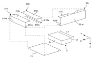
- FIG. 2 shows an exploded perspective view of the battery pack and the battery side bracket.
- the battery pack 2 has a rectangular parallelepiped shape, and has a front side surface 2a which is a rectangular vehicle front side rectangular side surface facing the vehicle front direction and a rectangular rear side surface 2b facing the vehicle rear side.
- the battery pack 2 is arranged along the vehicle width direction (paper surface Y direction) so that the long sides of the front side surface 2a and the rear side surface 2b are orthogonal to the vehicle front-rear direction (paper surface X direction).
- the battery pack 2 has a size in which both ends in the vehicle width direction extend beyond the outer surfaces of the side rails 3L and 3R in the vehicle width direction.
- the length L2 of the long side of the front side surface 2a and the rear side surface 2b is longer than the length L1 between the side rails 3L and 3R.
- the undercover 23 directly mounts the battery pack 2, and is composed of, for example, a plate-shaped member.
- the undercover 23 is a cover that merely covers the lower surface of the battery pack 2, and the first brackets 21A and 21B are responsible for directly holding the battery pack 2.
- the front side first bracket 21A includes a first web 21Aw for covering the front side surface 2a of the battery pack 2 in this drawing. Further, a first upper flange 21At and a first lower flange 21Ab for covering a part of the upper surface continuous with the front side surface 2a of the battery pack 2 and a part of the lower surface continuous with the front side surface 2a are front surfaces. It is formed vertically and continuously with the first web 21Aw. That is, the first upper flange 21At and the first lower flange 21Ab are arranged so that the flat surfaces face each other in the vehicle height direction (paper surface Z direction). As a result, the front side first bracket 21A is formed in a substantially U shape whose cross section is open to the rear side of the vehicle.
- the rear first bracket 21B also includes a first web 21Bw for covering the rear side surface 2b of the battery pack 2. Further, a first upper flange 21Bt and a first lower flange 21Bb for covering a part of the upper surface continuous with the rear side surface 2b of the battery pack 2 and a part of the lower surface continuous with the rear side surface 2b are provided. There is. That is, the first upper flange 21Bt and the first lower flange 21Bb of the rear first bracket 21B are arranged so that the flat surfaces face each other in the vehicle height direction (paper surface Z direction). As a result, the rear first bracket 21B is formed in a substantially U shape whose cross section is open to the front side of the vehicle.
- first brackets 21A and 21B support the battery pack 2 so that their open sides face each other and sandwich the battery pack 2 in the front and rear.
- the left second bracket 22L is provided with a second web 22Lw that covers the opening surface of the left end portion of the first brackets 21A and 21B in the vehicle width direction. Further, the upper end of the second web 22Lw extends between the first upper flanges 21At and 21Bt of the first brackets 21A and 21B, respectively, and the first upper flanges 21At and 21Bt of the first brackets 21A and 21B. A second upper flange 22Lt connected to the outside is formed. Similarly, the lower end of the second web 22Lw extends between the first lower flanges 21Ab and 21Bb of the first brackets 21A and 21B, and the first lower flanges 21Ab and 21Bb of the first brackets 21A and 21B. A second lower flange 22Lb connected to the outside of the is formed.
- the length of the second upper flange 22Lt and the second lower flange 22Lb of the left second bracket 22L in the vehicle width direction is longer at the end than in the center in the vehicle front-rear direction.
- the central portion of the second upper flange 22Lt and the second lower flange 22Lb in the vehicle front-rear direction is cut out in an arc shape.
- the right side second bracket 22R has the same symmetrical configuration as the left side second bracket 22L, and the description thereof will be omitted.
- the battery side bracket 20 surrounds the four side surfaces of the battery pack 2 and a part of the upper surface and the lower surface in a box shape.
- the battery-side bracket 20 that surrounds the battery pack 2 in this way is connected to the side rails 3L and 3R via the frame-side bracket 30.
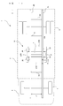
- FIG. 3 a cross-sectional view taken along the line AA of FIG. 1 is shown.
- the left side portion of the support device 10 suspended from the side rail 3L will be described as an example. Since the support device 10 on the right side suspended from the side rail 3R is symmetrical and has the same configuration, the description thereof will be omitted.
- the battery pack 2 is placed on the undercover 23, and the front and rear portions are covered with the first brackets 21A and 21B.
- the first webs 21Aw and 21Bw of the first brackets 21A and 21B, and the first upper flanges 21At and 21Bt are one of the corresponding surfaces (front side surface 2a, rear side surface 2b, upper surface) of the battery pack 2.
- the first lower flanges 21Ab and 21Bb are in contact with the undercover 23.
- the left side second bracket 22L covers the undercover 23 and the first brackets 21A and 21B from the outside with a gap S between the left side surface of the battery pack 2 and the vehicle width direction.
- the size of the gap S can be adjusted by changing the lengths of the second upper flange 22Lt of the left second bracket 22L and the second lower flange 22Lb in the vehicle width direction, and the first It can also be adjusted by changing the lengths of the brackets 21A and 21B in the vehicle width direction.
- the second lower flange 22Lb of the left side second bracket 22L is in contact with the first lower flanges 21Ab and 21b of the first brackets 21A and 21B, and the second lower side of the left side second bracket 22L.
- the flanges 22Lb, the first lower flanges 21Ab and 21b of the first brackets 21A and 21B, and the undercover 23 are connected by a plurality of bolts 40 (only one is described in FIG. 3).
- the second upper flange 22Lt of the left side second bracket 22L is in contact with the first upper flanges 21At and 21Bt of the first brackets 21A and 21B and the frame side bracket 30, and the left side second bracket 22L
- the second upper flange 22Lt, the first upper flanges 21At and 21Bt of the first brackets 21A and 21B, and the lower portion 30c of the frame side bracket 30 are connected by a plurality of bolts 41 (only one is described in FIG. 3). Has been done.
- the frame side bracket 30 is a member having an S-shaped cross section including an upper portion 30a, a central portion 30b, and a lower portion 30c, and ribs (not shown) are provided on the side surfaces for improving strength.
- the upper portion 30a of the frame-side bracket 30 is connected to the mount 31 by a plurality of bolts 42 (only one is described in FIG. 3).
- the mount 31 is a member that connects the frame side bracket 30 and the side rail 3L.
- the mount 31 is connected to the web 3Lw of the side rail 3L by a plurality of bolts 43 (only two are described in FIG. 3).
- the mount 31 is, for example, a rubber mount, which is provided with an elastic body such as rubber inside, and elastically holds the frame side bracket 30 with respect to the side rail 3L.
- the first brackets 21A and 21B having rigidity equivalent to that of the chassis frame are longer than the long sides of the front side surface 2a and the rear side surface 2b of the battery pack 2, and the front side surface 2a and the rear side surface 2b thereof.
- the second brackets 22L and 22R cover the vehicle width direction ends of the first brackets 21A and 21B, the torsional rigidity of the battery side bracket 20 is improved, and an object collides from the vehicle width direction side. Even if this happens, it is possible to prevent debris and the like from directly reaching the battery pack 2.
- the battery-side bracket 20 including the first brackets 21A and 21B and the second brackets 22L and 22R can be easily formed according to the shape of the battery pack 2. Then, the battery side bracket 20 is connected to the side rails 3L and 3R via the frame side bracket 30 to support the battery pack 2, so that the battery pack 2 having a size larger than that between the side rails 3L and 3R of the electric truck is supported. Can be easily mounted, and the torsional rigidity and lateral collision safety of the battery pack 2 can be ensured.
- the first upper flange 21At and the first lower flange 21Ab are continuously integrally formed with respect to the first web 21Aw covering the front side surface 2a of the battery pack 2.
- the second brackets 22L and 22R are connected to the first upper flanges 21At and 21Bt of the first brackets 21A and 21B, the second upper flanges 22Lt and 22Rt, and the first lower side of the first brackets 21A and 21B.
- the structure is such that the first brackets 21A and 21B are sandwiched and held, and the torsional rigidity of the battery side bracket 20 is improved. Can be done.
- the length in the vehicle width direction is longer than the central portion at the end portion in the vehicle front-rear direction.
- the torsional rigidity can be ensured while reducing the weight of the battery-side bracket 20.
- the second bracket since a gap S is formed between the second webs 22Lw and 22Rw of the second brackets 22L and 22R and the side surface of the battery pack 2 in the vehicle width direction, the second bracket receives an impact from the vehicle side. Even if the two brackets 22L and 22R are deformed, it is possible to prevent the second brackets 22L and 22R from directly contacting the battery pack 2 and transmitting an impact.
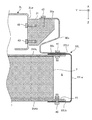
- FIG. 6 is a schematic top view of a vehicle provided with a vehicle battery pack support device according to another embodiment.
- three battery packs 2A, 2B, and 2C are supported side by side in the vehicle front-rear direction by the respective support devices 10A, 10B, and 10C.
- the battery pack 2B and the support device 10B at the center in the front-rear direction of the vehicle are the same as those in the above embodiment, whereas the battery pack 2A and the support device 10A on the front side of the vehicle are long in the vehicle width direction and offset to the right side of the vehicle. Has been done. Further, the battery pack 2C and the support device 10C on the rear side of the vehicle are longer in the front-rear direction of the vehicle than the central battery pack 2B and the support device 10B.
- the support devices 10A, 10B, and 10C can be easily adapted to the shape and layout of the battery packs 2A, 2B, and 2C, and each of them can exert the same effect as that of the above embodiment.
- the first brackets 21A and 21B of the battery side bracket 20 are composed of a pair of front and rear brackets, but the shape is not limited to this.
- two bracket members having an L-shaped cross section may be combined one above the other to form one of the first brackets.
- the pair of front and rear first brackets 21A and 21B may be integrally formed into a tubular shape. By doing so, the torsional rigidity of the battery-side bracket 20 is further improved.
Landscapes
- Engineering & Computer Science (AREA)
- Chemical & Material Sciences (AREA)
- Combustion & Propulsion (AREA)
- Transportation (AREA)
- Mechanical Engineering (AREA)
- Chemical Kinetics & Catalysis (AREA)
- Electrochemistry (AREA)
- General Chemical & Material Sciences (AREA)
- Aviation & Aerospace Engineering (AREA)
- Body Structure For Vehicles (AREA)
- Arrangement Or Mounting Of Propulsion Units For Vehicles (AREA)
- Battery Mounting, Suspending (AREA)
Priority Applications (3)
| Application Number | Priority Date | Filing Date | Title |
|---|---|---|---|
| US17/780,780 US12403757B2 (en) | 2019-11-29 | 2020-10-09 | Battery pack support device for vehicle |
| EP20894134.4A EP4063239B1 (en) | 2019-11-29 | 2020-10-09 | Vehicle with a battery pack support device |
| CN202080082755.4A CN114746326B (zh) | 2019-11-29 | 2020-10-09 | 车辆用电池包支承装置 |
Applications Claiming Priority (2)
| Application Number | Priority Date | Filing Date | Title |
|---|---|---|---|
| JP2019-217198 | 2019-11-29 | ||
| JP2019217198A JP7413739B2 (ja) | 2019-11-29 | 2019-11-29 | 車両用バッテリパック支持装置 |
Publications (1)
| Publication Number | Publication Date |
|---|---|
| WO2021106391A1 true WO2021106391A1 (ja) | 2021-06-03 |
Family
ID=76088300
Family Applications (1)
| Application Number | Title | Priority Date | Filing Date |
|---|---|---|---|
| PCT/JP2020/038377 Ceased WO2021106391A1 (ja) | 2019-11-29 | 2020-10-09 | 車両用バッテリパック支持装置 |
Country Status (5)
| Country | Link |
|---|---|
| US (1) | US12403757B2 (https=) |
| EP (1) | EP4063239B1 (https=) |
| JP (1) | JP7413739B2 (https=) |
| CN (1) | CN114746326B (https=) |
| WO (1) | WO2021106391A1 (https=) |
Cited By (1)
| Publication number | Priority date | Publication date | Assignee | Title |
|---|---|---|---|---|
| CN117715794A (zh) * | 2021-07-21 | 2024-03-15 | 戴姆勒卡车股份公司 | 卡车车辆 |
Families Citing this family (10)
| Publication number | Priority date | Publication date | Assignee | Title |
|---|---|---|---|---|
| JP7525365B2 (ja) * | 2020-10-09 | 2024-07-30 | ダイムラー トラック エージー | バッテリパックの支持装置、及び電動トラック |
| EP3981631B1 (en) * | 2020-10-12 | 2024-12-18 | Volvo Truck Corporation | A battery assembly |
| JP7714388B2 (ja) * | 2021-06-30 | 2025-07-29 | ダイムラー トラック エージー | 車両用バッテリパックの支持装置 |
| JP7714389B2 (ja) * | 2021-06-30 | 2025-07-29 | ダイムラー トラック エージー | 車両用バッテリパックの支持装置 |
| JP7804534B2 (ja) * | 2022-05-26 | 2026-01-22 | ダイムラー トラック エージー | 駆動用バッテリの支持装置 |
| JP2023173570A (ja) * | 2022-05-26 | 2023-12-07 | ダイムラー トラック エージー | 駆動用バッテリの支持装置 |
| JP7666480B2 (ja) * | 2022-10-11 | 2025-04-22 | トヨタ自動車株式会社 | フレーム車のバッテリ搭載構造 |
| JP7694527B2 (ja) * | 2022-10-11 | 2025-06-18 | トヨタ自動車株式会社 | フレーム車のバッテリ搭載構造 |
| CN115891607A (zh) * | 2022-11-29 | 2023-04-04 | 东风汽车股份有限公司 | 一种用于滑板式底盘的ctc电池包 |
| EP4656427A1 (en) * | 2024-05-27 | 2025-12-03 | Volvo Truck Corporation | Battery pack support system |
Citations (6)
| Publication number | Priority date | Publication date | Assignee | Title |
|---|---|---|---|---|
| JP2013067255A (ja) * | 2011-09-22 | 2013-04-18 | Nissan Motor Co Ltd | 電気自動車のバッテリパック車体支持構造 |
| JP2014069686A (ja) * | 2012-09-28 | 2014-04-21 | Mitsubishi Motors Corp | トラック形電動車両のフレーム構造 |
| JP2016113063A (ja) | 2014-12-16 | 2016-06-23 | ダイムラー・アクチェンゲゼルシャフトDaimler AG | バッテリボックスの保持構造 |
| JP2018118673A (ja) * | 2017-01-26 | 2018-08-02 | 日産ライトトラック株式会社 | 車両のバッテリ支持構造 |
| US20190084441A1 (en) * | 2017-09-15 | 2019-03-21 | Ford Global Technologies, Llc | Bracket attachment structure having an internal plate |
| JP2019156030A (ja) * | 2018-03-09 | 2019-09-19 | トヨタ自動車株式会社 | 車両下部構造 |
Family Cites Families (22)
| Publication number | Priority date | Publication date | Assignee | Title |
|---|---|---|---|---|
| JP6136187B2 (ja) * | 2012-10-16 | 2017-05-31 | トヨタ自動車株式会社 | 車両用電池搭載構造 |
| CN104802860B (zh) * | 2014-01-27 | 2019-06-07 | 比亚迪股份有限公司 | 电动卡车的车架组件和电动卡车 |
| JP6520808B2 (ja) | 2016-04-21 | 2019-05-29 | トヨタ自動車株式会社 | 車両のバッテリ搭載構造 |
| JP6512163B2 (ja) | 2016-04-21 | 2019-05-15 | トヨタ自動車株式会社 | 車両のバッテリ搭載構造 |
| DE102016113759A1 (de) * | 2016-07-26 | 2017-04-20 | Daimler Ag | Befestigungsanordnung einer Batterieeinrichtung an einem Rahmen eines Nutzfahrzeugs |
| US10112470B2 (en) * | 2017-01-11 | 2018-10-30 | GM Global Technology Operations LLC | Structural enhancements of an electric vehicle |
| JP6848543B2 (ja) | 2017-03-07 | 2021-03-24 | 三菱自動車工業株式会社 | 電動車両の車体構造 |
| US10637023B2 (en) * | 2017-09-06 | 2020-04-28 | Benteler Automobiltechnik Gmbh | Battery carrier for an electric motor vehicle |
| JP6667563B2 (ja) | 2018-03-19 | 2020-03-18 | 本田技研工業株式会社 | 車体後部構造 |
| DE102018205234B3 (de) * | 2018-04-06 | 2019-08-08 | Ford Global Technologies, Llc | Batterieanordnung für ein Elektrofahrzeug oder Hybridelektrofahrzeug |
| JP7163059B2 (ja) * | 2018-04-27 | 2022-10-31 | メルセデス・ベンツ グループ アクチェンゲゼルシャフト | 車両用バッテリハウジング、車両用バッテリパック、及び電動車両 |
| JP7057712B2 (ja) | 2018-04-27 | 2022-04-20 | ダイムラー・アクチェンゲゼルシャフト | 車両用バッテリパックの支持装置 |
| CA3110459C (en) * | 2018-08-24 | 2024-06-18 | Hexagon Purus North America Holdings Inc. | Battery system for heavy duty vehicles |
| JP2020035717A (ja) * | 2018-08-31 | 2020-03-05 | 本田技研工業株式会社 | 電池パック及び電池パックの製造方法 |
| JP7225257B2 (ja) * | 2018-09-20 | 2023-02-20 | 三洋電機株式会社 | 電源装置及び電源装置を備える車両並びに蓄電装置 |
| US10493837B1 (en) * | 2018-10-11 | 2019-12-03 | Paccar Inc | Chassis mounted assemblies for electric or hybrid vehicles |
| US11040610B2 (en) * | 2019-04-19 | 2021-06-22 | Hexagon Purus North America Holdings Inc. | Electric powertrain system for heavy duty vehicles |
| FR3099457A1 (fr) * | 2019-07-31 | 2021-02-05 | Faurecia Systemes D'echappement | Chassis de véhicule et véhicule associé |
| DE102019124066B4 (de) * | 2019-09-09 | 2022-11-24 | Kirchhoff Automotive Deutschland Gmbh | Rahmenstruktur |
| JP7422518B2 (ja) * | 2019-11-06 | 2024-01-26 | ダイムラー トラック エージー | 車両用バッテリパックの支持装置、及び、電動車両 |
| US11124076B1 (en) * | 2020-11-30 | 2021-09-21 | Nikola Corporation | Electric vehicle battery frame assembly |
| CA3227982A1 (en) * | 2021-08-26 | 2023-03-02 | Hexagon Purus North America Holdings Inc. | Battery packs for utility vehicle electric drivetrains |
-
2019
- 2019-11-29 JP JP2019217198A patent/JP7413739B2/ja active Active
-
2020
- 2020-10-09 CN CN202080082755.4A patent/CN114746326B/zh active Active
- 2020-10-09 EP EP20894134.4A patent/EP4063239B1/en active Active
- 2020-10-09 WO PCT/JP2020/038377 patent/WO2021106391A1/ja not_active Ceased
- 2020-10-09 US US17/780,780 patent/US12403757B2/en active Active
Patent Citations (6)
| Publication number | Priority date | Publication date | Assignee | Title |
|---|---|---|---|---|
| JP2013067255A (ja) * | 2011-09-22 | 2013-04-18 | Nissan Motor Co Ltd | 電気自動車のバッテリパック車体支持構造 |
| JP2014069686A (ja) * | 2012-09-28 | 2014-04-21 | Mitsubishi Motors Corp | トラック形電動車両のフレーム構造 |
| JP2016113063A (ja) | 2014-12-16 | 2016-06-23 | ダイムラー・アクチェンゲゼルシャフトDaimler AG | バッテリボックスの保持構造 |
| JP2018118673A (ja) * | 2017-01-26 | 2018-08-02 | 日産ライトトラック株式会社 | 車両のバッテリ支持構造 |
| US20190084441A1 (en) * | 2017-09-15 | 2019-03-21 | Ford Global Technologies, Llc | Bracket attachment structure having an internal plate |
| JP2019156030A (ja) * | 2018-03-09 | 2019-09-19 | トヨタ自動車株式会社 | 車両下部構造 |
Non-Patent Citations (1)
| Title |
|---|
| See also references of EP4063239A4 |
Cited By (1)
| Publication number | Priority date | Publication date | Assignee | Title |
|---|---|---|---|---|
| CN117715794A (zh) * | 2021-07-21 | 2024-03-15 | 戴姆勒卡车股份公司 | 卡车车辆 |
Also Published As
| Publication number | Publication date |
|---|---|
| US12403757B2 (en) | 2025-09-02 |
| EP4063239A4 (en) | 2023-02-08 |
| JP7413739B2 (ja) | 2024-01-16 |
| CN114746326A (zh) | 2022-07-12 |
| CN114746326B (zh) | 2024-01-12 |
| EP4063239B1 (en) | 2024-12-04 |
| JP2021084605A (ja) | 2021-06-03 |
| US20220410686A1 (en) | 2022-12-29 |
| EP4063239A1 (en) | 2022-09-28 |
Similar Documents
| Publication | Publication Date | Title |
|---|---|---|
| WO2021106391A1 (ja) | 車両用バッテリパック支持装置 | |
| CN112020448B (zh) | 车辆用电池组的支撑装置 | |
| CN109263456B (zh) | 车身结构 | |
| WO2018123337A1 (ja) | 電動車両のバッテリ保持装置 | |
| WO2019208749A1 (ja) | 車両用バッテリハウジング、車両用バッテリパック、及び電動車両 | |
| EP4368455A1 (en) | Truck vehicle | |
| JP2017019458A (ja) | 車両後部構造 | |
| JP2022025814A (ja) | 車両用バッテリパックの支持装置 | |
| JP2021133863A (ja) | 電動車両 | |
| JP7283006B2 (ja) | 電動トラック | |
| WO2020003836A1 (ja) | 車両用バッテリパック支持装置 | |
| JP2020023296A (ja) | 車両用バッテリパックの支持装置 | |
| JP2022038552A (ja) | 電動トラック | |
| WO2022049939A1 (ja) | 車両用バッテリパックの支持装置 | |
| JP2023090428A (ja) | バッテリパック支持装置 | |
| US12391131B2 (en) | Electric truck | |
| WO2019244858A1 (ja) | 車両用バッテリパック支持装置 | |
| WO2021153065A1 (ja) | サイドレール及び電動車両 | |
| JP2022085063A (ja) | バッテリパック支持装置 | |
| WO2022191264A1 (ja) | 車台 | |
| JP6795414B2 (ja) | 自動車の補助バッテリ配置構造 | |
| WO2025192743A1 (ja) | 車載機器の取付構造 |
Legal Events
| Date | Code | Title | Description |
|---|---|---|---|
| 121 | Ep: the epo has been informed by wipo that ep was designated in this application |
Ref document number: 20894134 Country of ref document: EP Kind code of ref document: A1 |
|
| NENP | Non-entry into the national phase |
Ref country code: DE |
|
| ENP | Entry into the national phase |
Ref document number: 2020894134 Country of ref document: EP Effective date: 20220622 |
|
| WWG | Wipo information: grant in national office |
Ref document number: 17780780 Country of ref document: US |