WO2021153065A1 - サイドレール及び電動車両 - Google Patents
サイドレール及び電動車両 Download PDFInfo
- Publication number
- WO2021153065A1 WO2021153065A1 PCT/JP2020/046986 JP2020046986W WO2021153065A1 WO 2021153065 A1 WO2021153065 A1 WO 2021153065A1 JP 2020046986 W JP2020046986 W JP 2020046986W WO 2021153065 A1 WO2021153065 A1 WO 2021153065A1
- Authority
- WO
- WIPO (PCT)
- Prior art keywords
- region
- vehicle
- overlapping
- battery pack
- side rail
- Prior art date
Links
Images


Classifications
-
- B—PERFORMING OPERATIONS; TRANSPORTING
- B60—VEHICLES IN GENERAL
- B60K—ARRANGEMENT OR MOUNTING OF PROPULSION UNITS OR OF TRANSMISSIONS IN VEHICLES; ARRANGEMENT OR MOUNTING OF PLURAL DIVERSE PRIME-MOVERS IN VEHICLES; AUXILIARY DRIVES FOR VEHICLES; INSTRUMENTATION OR DASHBOARDS FOR VEHICLES; ARRANGEMENTS IN CONNECTION WITH COOLING, AIR INTAKE, GAS EXHAUST OR FUEL SUPPLY OF PROPULSION UNITS IN VEHICLES
- B60K1/00—Arrangement or mounting of electrical propulsion units
- B60K1/04—Arrangement or mounting of electrical propulsion units of the electric storage means for propulsion
-
- B—PERFORMING OPERATIONS; TRANSPORTING
- B62—LAND VEHICLES FOR TRAVELLING OTHERWISE THAN ON RAILS
- B62D—MOTOR VEHICLES; TRAILERS
- B62D21/00—Understructures, i.e. chassis frame on which a vehicle body may be mounted
- B62D21/02—Understructures, i.e. chassis frame on which a vehicle body may be mounted comprising longitudinally or transversely arranged frame members
Definitions
- This case relates to a side rail arranged on the outside in the vehicle width direction of the battery pack and an electric vehicle equipped with this side rail.
- the battery pack placed between the side rails as described above is supported from below by a lifter such as a hydraulic lifting device when it is attached to or removed from the side rails in the vehicle manufacturing process or maintenance process. It can be moved in the width direction through the space below the rail.
- a lifter such as a hydraulic lifting device when it is attached to or removed from the side rails in the vehicle manufacturing process or maintenance process. It can be moved in the width direction through the space below the rail.
- the battery pack whose height dimension (dimension in the vehicle height direction when mounted on the vehicle) has been increased due to the increase in size may not be able to pass through the space below the side rail while being mounted on the lifter. In such a case, in order to avoid interference between the battery pack and the side rails, it is necessary to lift the entire vehicle body including the side rails, which complicates the work process and increases the equipment cost.
- the side rail according to the present application example is arranged outside the battery pack in the vehicle width direction in the vehicle, and includes a first region including an overlapping portion overlapping the battery pack in the vehicle width direction. A second region adjacent to the first region in the vehicle length direction is provided, and the lower end of the first region is higher in the vehicle height direction than the lower end of the second region.
- the distance between the lower end of the first region and the ground becomes longer than the distance between the lower end of the second region and the ground.
- a large space (dimension in the vehicle height direction) for moving the battery is secured. Therefore, when moving the battery pack through the space below the first region, it becomes easy to avoid interference between the lower end of the first region and the battery pack.
- the lower end of the end portion of the first region in the vehicle length direction may be higher in the vehicle height direction so as to be separated from the lower end of the adjacent second region. If the lower end of the end portion in the vehicle length direction of the first region is configured in this way, the cross section of the side rail (in the vehicle width direction and the vehicle height direction) at the connecting portion between the first region and the second region adjacent thereto is configured. Sudden changes in the cross section along the line) are suppressed. As a result, sudden changes in the strength and rigidity of the side rails are suppressed in the vehicle length direction, so that stress concentration is alleviated. Therefore, the deformation of the side rail is suppressed.
- the lower end of the intermediate portion between the ends of the first region may have a constant height in the vehicle height direction. If the lower end of the intermediate portion in the vehicle length direction of the first region is configured in this way, a large space for moving the battery pack is secured below the intermediate portion. Interference is more likely to be avoided. Therefore, the workability of attaching and detaching the battery pack is improved.
- the dimension in the vehicle height direction of the first region may be smaller than the dimension in the vehicle height direction of the second region.
- the dimension in the vehicle height direction is smaller in the first region than in the second region in this way, the space for moving the battery pack is secured below the first region, while the strength and rigidity are secured in the second region. Will be done.
- the height of the upper end of the first region may be constant in the vehicle height direction. If the upper end of the first region is configured in this way, the first region has a simple shape, and it becomes easy to arrange another device on the first region.
- the upper end of the end portion of the first region in the vehicle length direction may be flush with the upper end of the adjacent second region. If the upper end of the end portion in the vehicle length direction of the first region is configured in this way, the connecting portion between the first region and the second region adjacent thereto has a simple shape, so that the first region and the first region are formed. It becomes easy to arrange another device on the connecting portion with the two regions.
- the first region and the second region may have the same dimensions in the vehicle height direction. If the dimensions in the vehicle height direction are equal in the first region and the second region in this way, sudden changes in the cross section of the side rail are suppressed at the connecting portion between the first region and the second region. As a result, sudden changes in the strength and rigidity of the side rails are suppressed in the vehicle length direction, so that stress concentration is alleviated. Therefore, the deformation of the side rail is suppressed. Further, by ensuring the same strength and rigidity as the second region in the first region, deformation of the first region is suppressed.
- the electric vehicle according to the present application example is characterized by including the side rail according to any one of (1) to (7) above.
- the provision of the side rails simplifies the work process and suppresses the equipment cost in attaching and detaching the battery pack.
- the electric vehicle according to the present application example may include a plurality of cross members arranged between the pair of the side rails, connecting the side rails to each other, and forming a rudder frame together with the side rails. Even in an electric vehicle provided with such a rudder frame, the provision of the side rails simplifies the work process and suppresses the equipment cost in attaching and detaching the battery pack.
- the work process when installing and removing the battery pack, the work process can be simplified and the equipment cost can be suppressed.
- FIG. 1 It is a top view which shows schematic the whole structure of the electric vehicle provided with the side rail which concerns on 1st Embodiment. It is a schematic cross-sectional view (II-II arrow cross-sectional view of FIG. 1) which looked at the battery pack mounted on the electric vehicle of FIG. 1 and its periphery from the front. It is a view (side view) which looked at the main part of the electric vehicle of FIG. 1 from the outside in the vehicle width direction. Both (a) and (b) are schematic views illustrating the procedure for attaching and detaching the battery pack in the electric vehicle of FIG. It is a figure (the figure corresponding to FIG.
- the side rail 1 according to the first embodiment is applied to the vehicle 20 shown in FIG.
- the forward direction of the vehicle 20 is referred to as the front (FR)
- the opposite direction is referred to as the rear
- the front-rear direction is also referred to as the vehicle length direction.
- the left side (LH) and the right side are determined based on the state in which the vehicle 2 faces the front, and the left-right direction is also referred to as a vehicle width direction.
- a direction orthogonal to both the vehicle length direction and the vehicle width direction is also referred to as a vehicle height direction, and upward (UP) and downward are defined along the vehicle height direction.
- the vehicle 20 of the present embodiment is an electric vehicle including a battery pack 30 for driving and a pair of side rails 1 arranged on the outer side of the battery pack 30 in the vehicle width direction.
- a vehicle 20 which is a truck (electric truck) is illustrated.
- the vehicle 20 includes a plurality of cross members 2 that form a rudder frame 40 together with the side rail 1, and a drive device 50 that runs the vehicle 20 with the electric power of the battery pack 30.
- the cab 21 in which the driver's seat is provided and the packing box 22 arranged behind the cab 21 are shown by a two-dot chain line.
- Each side rail 1 extends in the vehicle length direction, and each cross member 2 extends in the vehicle width direction.
- the pair of side rails 1 are arranged apart from each other in the vehicle width direction.
- the cross members 2 are arranged apart from each other in the vehicle length direction between the pair of side rails 1 and connect the side rails 1 to each other.
- the ladder frame 40 composed of the side rail 1 and the cross member 2 is a ladder-type structure that supports heavy objects such as a battery pack 30, a drive device 50, a cab 21, and a packing box 22.
- the drive device 50 includes a motor unit 51 that operates with the electric power of the battery pack 30, and a gear unit 52 to which rotational force is transmitted from the motor unit 51.
- the gear unit 52 includes a well-known reduction mechanism and a differential mechanism, and after decelerating the rotational force transmitted from the motor unit 51 as necessary, the left and right rear wheels (driving wheels) via the rear axle 23. Communicate to 24.
- the vehicle 20 travels by transmitting the rotational force from the drive device 50 to the rear wheels 24 in this way.
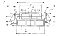
- the battery pack 30 is a relatively large and large-capacity secondary battery, and is arranged between a pair of side rails 1 in front of the drive device 50. As shown in FIG. 2, the battery pack 30 is housed in each of the first battery housing 31 and the second battery housing 32 and the first battery housing 31 and the second battery housing 32 arranged in the vehicle height direction. It also has a plurality of batteries 33.
- the first battery accommodating portion 31 of the present embodiment has a shape as if one corner of a rectangular parallelepiped is cut off (see FIG. 3). More specifically, the first battery accommodating portion 31 has a recess 31c in which the upper portion of the front surface 31b facing forward while mounted on the vehicle 20 is recessed in a rectangular parallelepiped shape. The first battery accommodating portion 31 is arranged in the first space S1 between the pair of side rails 1. On the other hand, the second battery accommodating portion 32 of the present embodiment has a rectangular parallelepiped shape. The second battery accommodating portion 32 is arranged in the second space S2 below the first space S1 and is continuous with the first battery accommodating portion 31.
- the first space S1 is a space hidden by the side rail 1 in the side view (vehicle width direction view) of the vehicle 20.
- the second space S2 is a space below the side rail 1 and is not hidden by the side rail 1 when viewed from the side of the vehicle 20.
- At least a part of the first battery accommodating portion 31 of the present embodiment is arranged in the first space S1, and at least a part of the first battery accommodating portion 31 overlaps with the side rail 1 in the side view of the vehicle 20.
- the entire second battery accommodating portion 32 of the present embodiment is arranged in the second space S2, and the entire portion does not overlap with each side rail 1 in the side view of the vehicle 20.
- the first battery accommodating portion 31 is mounted on the second battery accommodating portion 32.
- the first battery accommodating portion 31 and the second battery accommodating portion 32 are fixed to each other.
- the vehicle width direction dimension W2 of the second battery accommodation unit 32 is set larger than the vehicle width direction dimension W1 of the first battery accommodation unit 31.
- the vehicle width direction dimension W1 of the first battery accommodating portion 31 is smaller than the distance X between the pair of side rails 1 (W1 ⁇ X), and the vehicle width direction dimension W2 of the second battery accommodating portion 32 is the above distance.
- An example larger than X (W2> X) is shown.
- the distance X between the pair of side rails 1 is projected inward in the vehicle width direction from the upper and lower edges of the plate-shaped web 1a along the vehicle length direction and the vehicle height direction in each side rail 1.
- the distance is based on the tip (protruding end) of the flange 1b. Therefore, the above distance X corresponds to the length in the vehicle width direction between the right end of the flange 1b on the left side rail 1 and the left end of the flange 1b on the right side rail 1.
- the first battery accommodating portion 31 and the second battery accommodating portion 32 are arranged so that the center lines in the vehicle width direction (see the alternate long and short dash line in FIG. 2) coincide with each other.
- the battery pack 30 has a T-shape (inverted T-shape) that is upside down in front view (viewing in the direction of the vehicle length).
- the plurality of batteries 33 are connected in series and function as an energy source for driving the vehicle 20.
- the number and arrangement of the batteries 33 are not particularly limited, and can be appropriately changed according to the amount of electric power required to drive the vehicle 20, the dimensions and characteristics of the batteries 33, and the like.
- the battery pack 30 is connected to the side rail 1 via the support device 10.
- the support device 10 of the present embodiment elastically attaches the frame-side bracket 11 coupled to the ladder frame 40, the battery-side bracket 12 coupled to the battery pack 30, and the frame-side bracket 11 and the battery-side bracket 12 thereof. It has an elastic connecting portion 13 for connecting.
- the support device 10 elastically supports the battery pack 30 with respect to the rudder frame 40 by the configuration in which the frame side bracket 11 and the battery side bracket 12 are connected via the elastic connecting portion 13 in this way, and the rudder frame 40 The vibration transmitted from the battery pack 30 to the battery pack 30 is reduced.
- the support device 10 in which the frame side bracket 11, the battery side bracket 12, and the elastic connecting portion 13 are arranged three by three at intervals in the vehicle length direction on the left and right sides of the battery pack 30 is illustrated. (See FIGS. 1 and 3). Therefore, the battery pack 30 of the present embodiment is attached to the ladder frame 40 via the battery-side brackets 11 (six sets), the frame-side brackets 12, and the elastic connecting portions 13 provided in sixs each.
- the support device 10 of the present embodiment is formed symmetrically.
- Each frame side bracket 11 extends outward and downward in the vehicle width direction from the side rail 1.
- the upper portion of each frame side bracket 11 is arranged outside the web 1a of the side rail 1 in the vehicle width direction, and is connected to the side rail 1 by a fixture 14 such as a bolt.
- each battery-side bracket 12 projects from the end surface 32a on the outer side in the vehicle width direction of the second battery accommodating portion 32 to the outer side in the vehicle width direction.
- Each elastic connecting portion 13 is, for example, a rubber bush, and includes an elastic body having a substantially cylindrical shape or a substantially truncated cone shape.
- the elastic connecting portion 13 absorbs external force input in various directions (vehicle length direction, vehicle width direction, vehicle height direction, and a composite direction combining these directions).
- the elastic connecting portion 13 is fixed to each of the lower portion of the frame side bracket 11 and the outer end portion of the battery side bracket 12 in the vehicle width direction. As a result, the elastic connecting portion 13 elastically connects the frame-side bracket 11 and the battery-side bracket 12.
- the method of fixing the elastic connecting portion 13 is not particularly limited, and for example, a fixing tool such as a bolt may be used, or a method of matching the irregularities provided on each portion of the elastic connecting portion 13 is adopted. You may.
- the side rail 1 has a first region 3 including an overlapping portion 6 overlapping with the battery pack 30 in the side view of the vehicle 20, and a second region 4 adjacent to the first region 3 in the vehicle length direction. , 5 and are provided.
- the first region 3 is aligned with the battery pack 30 in the vehicle width direction, and the second regions 4 and 5 are located in front of or behind the battery pack 30.
- the overlapping portion 6 which is a part thereof overlaps with the battery pack 30 in a state of being mounted on the vehicle 20 (hereinafter, also referred to as “mounted state”) in a side view.
- the second regions 4 and 5 as a whole do not overlap with the battery pack 30 in the mounted state in a side view.
- the second regions 4 and 5 of the present embodiment are provided adjacent to both sides (front and rear) of the first region 3 in the vehicle length direction.
- one of the second regions 4 and 5 provided adjacent to the front of the first region 3 and located in front of the battery pack 30 is also referred to as a "front region 4" and is behind the first region 3.
- the other adjacent battery pack 30 located behind the battery pack 30 is also referred to as a "rear region 5".
- the first region 3 is also referred to as "overlapping region 3".
- the side rail 1 has a channel shape having a cross section (a cross section along the vehicle width direction and the vehicle height direction) of the above-mentioned web 1a and flange 1b in any of the overlapping region 3, the front region 4, and the rear region 5. Make up.
- the height dimension L1 of the overlapping region 3 of the present embodiment is any of the height dimensions L2 and L3 of the front region 4 and the rear region 5. Less than (L1 ⁇ L2 and L1 ⁇ L3). However, the height dimension L1 of the overlapping region 3 is not constant (uniform), and is larger at the end portions 3a and 3b than at the intermediate portion 3c in the vehicle height direction. On the other hand, the height dimension L2 of the front region 4 is constant, and the height dimension L3 of the rear region 5 is also constant.
- the term "constant” here does not have to be strictly defined as one value, and errors that may occur in design and manufacturing are allowed.
- the heights of the lower end 7L of the overlapping region 3, the lower end 8L of the front region 4, and the lower end 9L of the rear region 5 in the vehicle height direction (hereinafter, also referred to as “height position”) will be described in detail.
- the side rail 1 of the present embodiment has a channel shape as described above, the lower ends 7L, 8L, and 9L here correspond to the lower surface (the surface facing downward) of the lower flange 1b at the corresponding portion. do.
- the lower end 7L of the overlapping region 3 (hereinafter, also referred to as “overlapping lower end 7L”) corresponds to the lower surface of the lower flange 1b in the overlapping region 3.
- the lower end 8L of the front region 4 corresponds to the lower surface of the lower flange 1b in the front region 4, and the lower end 9L of the rear region 5 (hereinafter, “rear lower end 9L”). (Also referred to as) corresponds to the lower surface of the lower flange 1b in the rear region 5.
- the overlapping lower end 7L is higher (located above) in the vehicle height direction than either the front lower end 8L or the rear lower end 9L. Therefore, the distance D1 between the overlapping lower end 7L and the ground G is longer than any of the distance D2 between the front lower end 8L and the ground G and the distance D3 between the rear lower end 9L and the ground G. As described above, a large space for moving the battery pack 30 is secured below the overlapping region 3 as compared with below the front region 4 and the rear region 5.
- the height position of the overlapping lower end 7L of the present embodiment is different between the end portions 3a and 3b in the vehicle length direction and the intermediate portion 3c in the overlapping region 3.
- the front end portion 3a is also referred to as “overlapping front end portion 3a”
- the rear end portion 3b is also referred to as “overlapping rear end portion 3b”.
- the symbol "7a” is attached to the lower end of the overlapping front end portion 3a
- the symbol “7b” is attached to the lower end of the overlapping rear end portion 3b
- the symbol “7c” is attached to the lower end of the intermediate portion 3c.
- the intermediate portion 3c is a portion between the overlapping front end portion 3a and the overlapping rear end portion 3b.
- the lower end 7a of the overlapping front end 3a is continuous from the front lower end 8L and is inclined upward toward the rear. As described above, the lower end 7a of the overlapping front end portion 3a becomes higher in the vehicle height direction so as to be separated from the lower end 8L of the front region 4 adjacent to the overlapping front end portion 3a. Further, the lower end 7b of the overlapping rear end portion 3b is continuous from the rear lower end 9L and is inclined upward toward the front. As described above, the lower end 7b of the overlapping rear end portion 3b becomes higher in the vehicle height direction so as to be separated from the lower end 9L of the rear region 5 adjacent to the overlapping rear end portion 3b.
- the lower ends 7a and 7b of the overlapping front end portion 3a and the overlapping rear end portion 3b have a function of suppressing a sudden change in the cross section in the overlapping region 3.
- the lower end 7c of the intermediate portion 3c is continuous from the lower ends 7a and 7b of the overlapping front end portion 3a and the overlapping rear end portion 3b, and the height position is constant. Therefore, in the overlapping region 3, the lower end 7c of the intermediate portion 3c extends in a straight line along the vehicle length direction above the lower ends 7a and 7b of the overlapping front end portion 3a and the overlapping rear end portion 3b.
- the front lower end 8L and the rear lower end 9L each have a constant height position, and extend in a straight line along the vehicle length direction below the overlapping lower end 7L.
- the height positions of the upper end 7U of the overlapping region 3, the upper end 8U of the front region 4, and the upper end 9U of the rear region 5 will be described in detail.
- the side rail 1 of the present embodiment has a channel shape as described above, the upper ends 7U, 8U, and 9U here correspond to the upper surface (the surface facing upward) of the upper flange 1b at the corresponding portion. ..
- the upper end 7U of the overlapping region 3 (hereinafter, also referred to as “overlapping upper end 7U”) corresponds to the upper surface of the upper flange 1b in the overlapping region 3.
- front upper end 8U corresponds to the upper surface of the upper flange 1b in the front region 4
- rear upper end 9U corresponds to the upper surface of the upper flange 1b in the rear region 5.
- the height positions of the overlapping upper end 7U, the front upper end 8U, and the rear upper end 9U are all constant. Therefore, the overlapping upper end 7U, the front upper end 8U, and the rear upper end 9U extend in a straight line along the vehicle length direction above the overlapping lower end 7L, the front lower end 8L, and the rear lower end 9L.
- the upper end of the overlapping front end portion 3a is designated by the symbol "7d”
- the upper end of the overlapping rear end portion 3b is designated by the symbol "7e”
- the upper end of the intermediate portion 3c is designated by the symbol "7f”. Is attached.
- the upper end 7d of the overlapping front end portion 3a is flush with the upper end 8U of the front region 4 adjacent to the overlapping front end portion 3a.
- the upper end 7e of the overlapping rear end 3b is flush with the upper end 9U of the rear region 5 adjacent to the overlapping rear end 3b.
- the mounted battery pack 30 is provided with the height position of the upper surface (upper surface of the first battery accommodating portion 31) 31a higher than the overlapping lower end 7L.
- the battery pack 30 in which the height position of the upper surface 31a is set higher than the overlapping lower end 7L and lower than the overlapping upper end 7U is illustrated.
- the height position of the upper surface 31a of the mounted battery pack 30 may be higher than the height position of the overlapping lower end 7L, and for example, the height position of the upper surface 31a may be set to be equal to or higher than the height position of the overlapping upper end 7U.
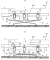
- the procedure for removing the battery pack 30 will be described. As shown in FIG. 4A, the lifter 60 is arranged below the battery pack 30, and the support surface 61 thereof is raised to support the battery pack 30 from below. Next, the fixture 14 is removed, and the battery pack 30 and the support device 10 are integrally separated from the side rail 1. As a result, the battery pack 30 can move relative to the side rail 1 together with the support device 10.
- the support surface 61 of the lifter 60 is lowered, and the battery pack 30 and the support device 10 are integrally lowered.
- the lifter 60 on which the battery pack 30 is placed is moved in the vehicle width direction to cover the overlapping area 3.
- the battery pack 30 and the support device 10 are taken out from the side rail 1 to the outside in the vehicle width direction through the space below.
- the overlap region 3 is larger in the vehicle height direction than the front region 4 and the rear region 5. Space is secured. Therefore, when the battery pack 30 is taken out through the space below the overlapping region 3, the upper surface 31a of the battery pack 30 is located lower than the overlapping lower end 7L even if it is higher than the front lower end 8L and the rear lower end 9L. If so, the battery pack 30 can be taken out.
- the overlapping lower end 7L is higher in the vehicle height direction than the front lower end 8L and the rear lower end 9L, the overlapping lower end 7L is at the same height position as the front lower end 8L or the rear lower end 9L. In comparison, interference between the overlapping lower end 7L and the battery pack 30 is more likely to be avoided.
- the battery pack 30 can be attached by reversing the removal procedure described above.
- the battery pack 30 and the support device 10 on the lifter 60 are moved from the outside to the inside in the vehicle width direction of the overlapping area 3 through the space below the overlapping area 3.
- the side rail 1 since the overlapping lower end 7L is higher in the vehicle height direction than the front lower end 8L and the rear lower end 9L as described above, interference between the overlapping lower end 7L and the battery pack 30 can be easily avoided.
- each frame side bracket 11 is connected to the side rail 1 by the fixture 14. Finally, the lifter 60 is lowered again and moved to the outside of the vehicle 20.
- a larger space (dimension in the vehicle height direction) for moving the battery pack 30 is secured below the overlapping region 3 than below the front region 4 and the rear region 5.
- the overlapping lower end 7L and the battery pack 30 are compared with the case where the overlapping lower end 7L is at the same height as the front lower end 8L or the rear lower end 9L. It becomes easier to avoid interference with.
- the battery pack 30 is moved through the space below the overlapping area 3 while avoiding interference between the overlapping lower end 7L and the battery pack 30 without having to lift the side rail 1 and the ladder frame 40 including the side rail 1. It becomes possible. Therefore, the work process of attaching and detaching the battery pack 30 can be simplified. Further, since the equipment for lifting the side rail 1 and the entire rudder frame 40 is not required, the equipment cost for attaching and detaching the battery pack 30 can be suppressed.
- the size limitation of the battery pack 30 can be relaxed by easily avoiding the interference between the overlapping lower end 7L and the battery pack 30 as described above. Therefore, by increasing the capacity (battery capacity) of the battery pack 30, it contributes to the extension of the cruising range of the vehicle 20.
- the battery pack 30 of the present embodiment has a relatively large height dimension (dimension in the vehicle height direction in the mounted state) because it includes the first battery accommodating portion 31 and the second battery accommodating portion 32. Therefore, even in such attachment and detachment of the battery pack 30, interference with the battery pack 30 can be easily avoided.
- the time required for replacing the battery pack 30 can be shortened. Therefore, when the charge amount of the battery pack 30 decreases, the battery pack 30 can be replaced with a fully charged battery pack in a short time. Therefore, it also contributes to securing the operating time of the vehicle 20.
- the overlapping area 3 can be made into a simpler shape as compared with the case where the height position of the overlapping upper end 7U is not constant. This makes it easy to place another device (eg, packing box 22) on the overlapping area 3.
- the height positions of the overlapping upper end 7U, the front upper end 8U, and the rear upper end 9U are constant, and these upper ends 7U, 8U, and 9U extend in a straight line along the vehicle length direction.
- the entire rail 1 can be made into a simpler shape. As a result, it becomes easy to arrange another device on the side rail 1 over the entire area in the vehicle length direction.
- connection part can be made into a simple shape. As a result, it becomes easy to arrange another device on each connection portion between the overlapping region 3 and the front region 4 and the rear region 5.
- the side rail 1 since the side rail 1 is configured as described above, the work process can be simplified and the equipment cost can be suppressed in the attachment and detachment of the battery pack 30.
- the vehicle 20 is provided with a plurality of cross members 2 constituting the rudder frame 40 together with the side rail 1. Even in the vehicle 20 provided with such a ladder frame 40, the side rail 1 can simplify the work process in attaching and detaching the battery pack 30 as described above, and can suppress the equipment cost.
- the side rail 1'of the second embodiment has a height dimension L1'of the overlapping region 3', the front region 4', and the rear region 5'with respect to the side rail 1 of the first embodiment. , L2', L3'are different.
- L1'of the overlapping region 3', the front region 4', and the rear region 5'with respect to the side rail 1 of the first embodiment L2', L3'are different.
- the same or corresponding elements as those described in the first embodiment are designated by the same reference numerals, and duplicate description will be omitted.
- the terms "equal” here do not have to be exactly the same, and errors that may occur in design and manufacturing are acceptable.
- the lower ends 7L, 8L, and 9L are the same as those of the first embodiment, whereas the upper ends 7U', 8U', and 9U are the same.
- the height position of ′ is not constant, and extends parallel to the corresponding lower ends 7L, 8L, and 9L, respectively. Therefore, the overlapping upper end 7U'of this embodiment is higher (located above) in the vehicle height direction than either the front upper end 8U' or the rear upper end 9U'.
- the height position of the upper end 7U' is different between the front end portion 3a', the rear end portion 3b', and the intermediate portion 3c'.
- the upper end 7d'of the overlapping front end 3a' is continuous from the front upper end 8U' and is inclined upward toward the rear.
- the upper end 7e'of the overlapping rear end portion 3b' is continuous from the rear upper end 9U' and is inclined upward toward the front.
- the upper ends 7d ′ and 7e ′ of the overlapping front end portion 3a ′ and the overlapping rear end portion 3b ′ have a function of suppressing a sudden change in the cross section in the overlapping region 3 ′.
- the upper end 7f'of the intermediate portion 3c' is continuous from the upper ends 7d' and 7e' of the overlapping front end portion 3a'and the overlapping rear end portion 3b', and the height position is constant. Therefore, in the overlapping region 3'of the present embodiment, the upper end 7f'of the intermediate portion 3c'is above the upper ends 7d'and 7e' of the overlapping front end portion 3a'and the overlapping rear end portion 3b'in the vehicle length direction. It extends in a straight line along.
- the front upper end 8U'and the rear upper end 9U' have constant height positions, and extend in a straight line along the vehicle length direction below the overlapping upper end 7U'.
- the height dimension L1'of the overlapping region 3' is the same as the height dimensions L2'and L3'of the front region 4'and the rear region 5', the front region 4'and the rear region 3'are also the same. It is possible to secure the same strength and rigidity as the region 5'. Thereby, the deformation of the overlapping region 3'can be further suppressed.
- the side rail 1'of the present embodiment and the vehicle (electric vehicle) provided with the side rail 1' the same operation and effect can be obtained from the same configuration as that of the above embodiment.
- the above battery pack 30 is an example.
- the side rails 1, 1' may be arranged outside the battery pack 30'shown in FIG. 6 in the vehicle width direction instead of the battery pack 30 described above.
- FIG. 6 illustrates the side rail 1 of the first embodiment, the side rail 1'of the second embodiment can also be applied in the same manner.
- the same or corresponding elements as those described in the first embodiment are designated by the same reference numerals, and duplicate description will be omitted.
- the battery pack 30'of this modification has the shape of the first battery accommodating portion 31'and the dimension W2'in the vehicle width direction of the second battery accommodating portion 32'with respect to the battery pack 30 shown in the first embodiment. Is different. Specifically, in the battery pack 30', the first battery accommodating portion 31'has a rectangular parallelepiped shape (the recess 31c described above is omitted), and the vehicle width direction dimension W2'of the second battery accommodating portion 32'is It is set to be the same as the vehicle width direction dimension W1 of the first battery accommodating portion 31'.
- the first battery accommodating portion 31'and the second battery accommodating portion 32' are arranged so that the center lines in the vehicle width direction (see the alternate long and short dash line in FIG. 6) coincide with each other.
- the battery pack 30' forms a rectangular shape when viewed from the front (viewed in the direction of the vehicle length).
- the shape is simplified as compared with the battery pack 30 of each of the above embodiments.
- the specific shape and dimensions of the battery pack arranged between the side rails 1 and 1' are not particularly limited.
- the height dimension can be increased by omitting the above-mentioned second battery accommodating portions 32 and 32'. It may be reduced.
- the overlapping lower end 7L of the side rails 1, 1's may be higher in the vehicle height direction than the front lower end 8L and the rear lower end 9L, and the specific height position is not particularly limited.
- the height positions of the overlapping front end portions 3a, 3a'and the lower ends 7a, 7b of the overlapping rear end portions 3b, 3b' may be constant.
- the entire overlapping lower end 7L including the lower end 7c of the intermediate portions 3c and 3c' may be inclined up or down toward the front or the rear.
- the configuration of the support device 10 described above is an example.
- the vehicle 20 to which the side rails 1, 1'are applied is not limited to the electric vehicle provided with only the motor unit 51 as a drive source, but may be a hybrid vehicle further provided with an engine.
- the side rails 1, 1' can be applied to a vehicle not provided with the rudder frame 40, and may be applied to a commercial vehicle other than a truck.
- the above configuration of the side rails 1, 1' may be applied to only one of the side rails arranged on both sides of the battery packs 30 and 30'in the vehicle width direction in the vehicle 20.
Landscapes
- Engineering & Computer Science (AREA)
- Chemical & Material Sciences (AREA)
- Combustion & Propulsion (AREA)
- Transportation (AREA)
- Mechanical Engineering (AREA)
- Body Structure For Vehicles (AREA)
- Arrangement Or Mounting Of Propulsion Units For Vehicles (AREA)
Abstract
【課題】バッテリパックの取り付け及び取り外しにおいて、作業工程を簡易化すると共に設備コストを抑制する。 【解決手段】車両においてバッテリパック30の車幅方向外側に配置されるサイドレール1は、車幅方向視でバッテリパック30と重複する重複部6を含む第1領域3と、第1領域3と車長方向において隣接する第2領域4,5とを備える。第1領域3の下端7Lは、第2領域4,5の下端8L,9Lよりも車高方向において高くなっている。
Description
本件は、バッテリパックの車幅方向外側に配置されるサイドレール及びこのサイドレールを備えた電動車両に関する。
従来、環境への負荷を低減する観点から、駆動用のバッテリの電力をモータに供給することで走行する電気自動車やハイブリッド自動車等の電動車両の開発が進んでいる。近年では、トラックなどの商用車の分野においても、電動車両の開発が行われている(例えば特許文献1参照)。
一般に商用車は乗用車に比べて重量が大きいため、商用車としての電動車両では、航続距離の確保のために、複数のバッテリで構成されるバッテリパックの容量を増大させることが求められる。バッテリパックは、容量が増大するほど大型化する傾向にあるため、ラダーフレームを備える車両においては、レイアウトの関係上、一対のサイドレール間にバッテリパックが搭載されることとなる。
一般に商用車は乗用車に比べて重量が大きいため、商用車としての電動車両では、航続距離の確保のために、複数のバッテリで構成されるバッテリパックの容量を増大させることが求められる。バッテリパックは、容量が増大するほど大型化する傾向にあるため、ラダーフレームを備える車両においては、レイアウトの関係上、一対のサイドレール間にバッテリパックが搭載されることとなる。
上記のようにサイドレール間に配置されるバッテリパックは、車両の製造工程やメンテナンス工程でサイドレールへの取り付け,取り外しが行われる際に、油圧昇降装置などのリフターで下方から支持されつつ、サイドレールの下方のスペースを通じて車幅方向に移動させられる。
しかしながら、大型化に伴って高さ寸法(車両搭載状態における車高方向寸法)が拡大されたバッテリパックは、リフター上に載置された状態でサイドレールの下方のスペースを通過できない場合がある。このような場合には、バッテリパックとサイドレールとの干渉回避のために、サイドレールを含む車体全体を持ち上げる作業が必要となり、作業工程の複雑化及び設備コストの上昇を招く。
しかしながら、大型化に伴って高さ寸法(車両搭載状態における車高方向寸法)が拡大されたバッテリパックは、リフター上に載置された状態でサイドレールの下方のスペースを通過できない場合がある。このような場合には、バッテリパックとサイドレールとの干渉回避のために、サイドレールを含む車体全体を持ち上げる作業が必要となり、作業工程の複雑化及び設備コストの上昇を招く。
本件は、上記のような課題に鑑み創案されたものであり、バッテリパックの取り付け及び取り外しにおいて、作業工程を簡易化すると共に設備コストを抑制することを目的の一つとする。
本件は上記の課題の少なくとも一部を解決するためになされたものであり、以下の態様又は適用例として実現できる。
(1)本適用例に係るサイドレールは、車両においてバッテリパックの車幅方向外側に配置されるものであって、車幅方向視で前記バッテリパックと重複する重複部を含む第1領域と、前記第1領域と車長方向において隣接する第2領域と、を備え、前記第1領域の下端は、前記第2領域の下端よりも車高方向において高いことを特徴としている。
(1)本適用例に係るサイドレールは、車両においてバッテリパックの車幅方向外側に配置されるものであって、車幅方向視で前記バッテリパックと重複する重複部を含む第1領域と、前記第1領域と車長方向において隣接する第2領域と、を備え、前記第1領域の下端は、前記第2領域の下端よりも車高方向において高いことを特徴としている。
これにより、第1領域の下端と地面との距離が、第2領域の下端と地面との距離よりも長くなるため、第1領域の下方には、第2領域の下方と比べて、バッテリパックを移動させるためのスペース(車高方向寸法)が大きく確保される。したがって、第1領域の下方のスペースを通じてバッテリパックを移動させる際に、第1領域の下端とバッテリパックとの干渉を回避しやすくなる。
よって、サイドレールを持ち上げる作業を行わなくても、第1領域の下端とバッテリパックとの干渉を回避しながら、第1領域の下方のスペースを通じてバッテリパックを移動させることが可能となる。このため、バッテリパックの取り付け及び取り外しにおいて、作業工程が簡易化される。また、サイドレールを持ち上げるための設備が不要となることから、設備コストが抑制される。
(2)本適用例に係るサイドレールにおいて、前記第1領域の車長方向における端部の前記下端は、隣接する前記第2領域の前記下端から離隔するほど車高方向において高くてもよい。
第1領域の車長方向における端部の下端をこのように構成すれば、第1領域とこれに隣接する第2領域との接続部分においてサイドレールの横断面(車幅方向かつ車高方向に沿う断面)の急変が抑制される。これにより、車長方向において、サイドレールの強度及び剛性の急変が抑制されるため、応力集中が緩和される。したがって、サイドレールの変形が抑制される。
第1領域の車長方向における端部の下端をこのように構成すれば、第1領域とこれに隣接する第2領域との接続部分においてサイドレールの横断面(車幅方向かつ車高方向に沿う断面)の急変が抑制される。これにより、車長方向において、サイドレールの強度及び剛性の急変が抑制されるため、応力集中が緩和される。したがって、サイドレールの変形が抑制される。
(3)本適用例に係るサイドレールにおいて、前記第1領域の前記端部の間である中間部の前記下端は、車高方向における高さが一定であってもよい。
第1領域の車長方向における中間部の下端をこのように構成すれば、中間部の下方において、バッテリパックを移動させるためのスペースが大きく確保されるため、第1領域の下端とバッテリパックとの干渉がより回避されやすくなる。よって、バッテリパックの取り付け及び取り外しの作業性が高められる。
第1領域の車長方向における中間部の下端をこのように構成すれば、中間部の下方において、バッテリパックを移動させるためのスペースが大きく確保されるため、第1領域の下端とバッテリパックとの干渉がより回避されやすくなる。よって、バッテリパックの取り付け及び取り外しの作業性が高められる。
(4)本適用例に係るサイドレールにおいて、前記第1領域の車高方向の寸法は、前記第2領域の車高方向の寸法より小さくてもよい。
このように車高方向の寸法が第2領域よりも第1領域において小さければ、バッテリパックを移動させるためのスペースが第1領域の下方に確保されつつも、第2領域において強度及び剛性が確保される。
このように車高方向の寸法が第2領域よりも第1領域において小さければ、バッテリパックを移動させるためのスペースが第1領域の下方に確保されつつも、第2領域において強度及び剛性が確保される。
(5)本適用例に係るサイドレールにおいて、前記第1領域の上端は、車高方向における高さが一定であってもよい。
第1領域の上端がこのように構成されれば、第1領域がシンプルな形状となることで、第1領域の上に他の装置を配置することが容易となる。
第1領域の上端がこのように構成されれば、第1領域がシンプルな形状となることで、第1領域の上に他の装置を配置することが容易となる。
(6)本適用例に係るサイドレールにおいて、前記第1領域の車長方向における端部の上端は、隣接する前記第2領域の上端と面一であってもよい。
第1領域の車長方向における端部の上端がこのように構成されれば、第1領域とこれに隣接する第2領域との接続部分がシンプルな形状となることで、第1領域と第2領域との接続部分の上に他の装置を配置することが容易となる。
第1領域の車長方向における端部の上端がこのように構成されれば、第1領域とこれに隣接する第2領域との接続部分がシンプルな形状となることで、第1領域と第2領域との接続部分の上に他の装置を配置することが容易となる。
(7)本適用例に係るサイドレールにおいて、前記第1領域と前記第2領域とは、車高方向の寸法が互いに等しくてもよい。
このように車高方向の寸法が第1領域と第2領域とで等しければ、第1領域と第2領域との接続部分でサイドレールの横断面の急変が抑制される。これにより、車長方向において、サイドレールの強度及び剛性の急変が抑制されるため、応力集中が緩和される。したがって、サイドレールの変形が抑制される。また、第1領域において第2領域と同等の強度及び剛性が確保されることにより、第1領域の変形が抑制される。
このように車高方向の寸法が第1領域と第2領域とで等しければ、第1領域と第2領域との接続部分でサイドレールの横断面の急変が抑制される。これにより、車長方向において、サイドレールの強度及び剛性の急変が抑制されるため、応力集中が緩和される。したがって、サイドレールの変形が抑制される。また、第1領域において第2領域と同等の強度及び剛性が確保されることにより、第1領域の変形が抑制される。
(8)本適用例に係る電動車両は、上記(1)~(7)のいずれか一つに記載のサイドレールを備えることを特徴としている。
このような電動車両では、上記のサイドレールが設けられることにより、バッテリパックの取り付け及び取り外しにおいて、作業工程が簡易化されると共に設備コストが抑制される。
このような電動車両では、上記のサイドレールが設けられることにより、バッテリパックの取り付け及び取り外しにおいて、作業工程が簡易化されると共に設備コストが抑制される。
(9)本適用例に係る電動車両は、一対の前記サイドレール間に配置されて前記サイドレール同士を連結し、前記サイドレールと共にラダーフレームを構成する複数のクロスメンバを備えてもよい。
このようなラダーフレームを備える電動車両でも、上記のサイドレールが設けられることにより、バッテリパックの取り付け及び取り外しにおいて、作業工程が簡易化されると共に設備コストが抑制される。
このようなラダーフレームを備える電動車両でも、上記のサイドレールが設けられることにより、バッテリパックの取り付け及び取り外しにおいて、作業工程が簡易化されると共に設備コストが抑制される。
本件によれば、バッテリパックの取り付け及び取り外しにおいて、作業工程を簡易化できると共に設備コストを抑制できる。
図面を参照して、実施形態としてのサイドレール及び電動車両について説明する。以下の実施形態はあくまでも例示に過ぎず、この実施形態で明示しない種々の変形や技術の適用を排除する意図はない。下記の実施形態の各構成は、それらの趣旨を逸脱しない範囲で種々変形して実施できる。また、必要に応じて取捨選択でき、あるいは適宜組み合わせられる。
[1.第1実施形態]
[1-1.構成]
<車両>
第1実施形態に係るサイドレール1は、図1に示す車両20に適用されている。以下、車両20の前進方向を前方(FR)とし、この反対方向を後方とし、前後方向を車長方向ともいう。また、車両2の前方を向いた状態を基準にして左方(LH)及び右方を定め、左右方向を車幅方向ともいう。さらに、車長方向及び車幅方向のいずれにも直交する方向を車高方向ともいい、車高方向に沿って上方(UP)及び下方を定める。
[1-1.構成]
<車両>
第1実施形態に係るサイドレール1は、図1に示す車両20に適用されている。以下、車両20の前進方向を前方(FR)とし、この反対方向を後方とし、前後方向を車長方向ともいう。また、車両2の前方を向いた状態を基準にして左方(LH)及び右方を定め、左右方向を車幅方向ともいう。さらに、車長方向及び車幅方向のいずれにも直交する方向を車高方向ともいい、車高方向に沿って上方(UP)及び下方を定める。
本実施形態の車両20は、駆動用のバッテリパック30と、このバッテリパック30の車幅方向外側に配置された一対のサイドレール1とを備えた電動車両である。ここでは、トラック(電動トラック)である車両20を例示する。
車両20は、サイドレール1と共にラダーフレーム40を構成する複数のクロスメンバ2と、バッテリパック30の電力で車両20を走行させる駆動装置50とを備えている。なお、図1には、運転席が設けられるキャブ21と、キャブ21の後方に配置される荷箱22とを二点鎖線で示す。
車両20は、サイドレール1と共にラダーフレーム40を構成する複数のクロスメンバ2と、バッテリパック30の電力で車両20を走行させる駆動装置50とを備えている。なお、図1には、運転席が設けられるキャブ21と、キャブ21の後方に配置される荷箱22とを二点鎖線で示す。
各サイドレール1は車長方向に延在し、各クロスメンバ2は車幅方向に延在する。一対のサイドレール1は、車幅方向に互いに離間して配置される。一方、各クロスメンバ2は、一対のサイドレール1間において車長方向に互いに離間して配置され、サイドレール1同士を連結する。サイドレール1及びクロスメンバ2で構成されるラダーフレーム40は、バッテリパック30,駆動装置50,キャブ21及び荷箱22といった重量物を支持する梯子型の構造体である。
駆動装置50は、バッテリパック30の電力で作動するモータユニット51と、モータユニット51から回転力が伝達されるギアユニット52とを有する。ここでは、一対のサイドレール1の間に配置された駆動装置50を例示する。
ギアユニット52は、周知の減速機構や差動機構を含み、モータユニット51から伝達される回転力を、必要に応じて減速したうえで、リアアクスル23を介して左右の後輪(駆動輪)24に伝達する。車両20は、このように駆動装置50から後輪24に回転力が伝達されることにより走行する。
ギアユニット52は、周知の減速機構や差動機構を含み、モータユニット51から伝達される回転力を、必要に応じて減速したうえで、リアアクスル23を介して左右の後輪(駆動輪)24に伝達する。車両20は、このように駆動装置50から後輪24に回転力が伝達されることにより走行する。
バッテリパック30は、比較的大型かつ大容量の二次電池であり、駆動装置50よりも前方において一対のサイドレール1間に配置される。図2に示すように、バッテリパック30は、車高方向に並ぶ第1バッテリ収容部31及び第2バッテリ収容部32と、第1バッテリ収容部31及び第2バッテリ収容部32の各々に収容された複数のバッテリ33とを有する。
本実施形態の第1バッテリ収容部31は、直方体の一つの角部が削られたような形状である(図3参照)。より具体的には、第1バッテリ収容部31は、車両20に搭載された状態で前方を向く前面31bの上部が直方体形状に凹設されてなる凹部31cを有する。第1バッテリ収容部31は、一対のサイドレール1間である第1スペースS1に配置される。
一方、本実施形態の第2バッテリ収容部32は、直方体形状である。第2バッテリ収容部32は、第1スペースS1よりも下方の第2スペースS2に配置されると共に、第1バッテリ収容部31と連続する。
一方、本実施形態の第2バッテリ収容部32は、直方体形状である。第2バッテリ収容部32は、第1スペースS1よりも下方の第2スペースS2に配置されると共に、第1バッテリ収容部31と連続する。
ここで、第1スペースS1とは、車両20の側面視(車幅方向視)でサイドレール1に隠れる空間である。また、第2スペースS2とは、サイドレール1よりも下方の空間であって、車両20の側面視でサイドレール1に隠れない空間である。
本実施形態の第1バッテリ収容部31は、少なくとも一部が第1スペースS1に配置されており、車両20の側面視で少なくとも一部がサイドレール1と重複する。また、本実施形態の第2バッテリ収容部32は、その全体が第2スペースS2に配置されており、車両20の側面視でその全体が各サイドレール1と重複しない。
本実施形態の第1バッテリ収容部31は、少なくとも一部が第1スペースS1に配置されており、車両20の側面視で少なくとも一部がサイドレール1と重複する。また、本実施形態の第2バッテリ収容部32は、その全体が第2スペースS2に配置されており、車両20の側面視でその全体が各サイドレール1と重複しない。
第1バッテリ収容部31は、第2バッテリ収容部32上に載置されている。第1バッテリ収容部31と第2バッテリ収容部32とは、互いに固定されている。
本実施形態では、第1バッテリ収容部31の車幅方向寸法W1よりも、第2バッテリ収容部32の車幅方向寸法W2が大きく設定されている。ここでは、第1バッテリ収容部31の車幅方向寸法W1が一対のサイドレール1間の距離Xよりも小さく(W1<X)、第2バッテリ収容部32の車幅方向寸法W2が上記の距離Xよりも大きい(W2>X)例を示す。
本実施形態では、第1バッテリ収容部31の車幅方向寸法W1よりも、第2バッテリ収容部32の車幅方向寸法W2が大きく設定されている。ここでは、第1バッテリ収容部31の車幅方向寸法W1が一対のサイドレール1間の距離Xよりも小さく(W1<X)、第2バッテリ収容部32の車幅方向寸法W2が上記の距離Xよりも大きい(W2>X)例を示す。
一対のサイドレール1間の距離Xは、詳細には、各サイドレール1において、車長方向かつ車高方向に沿う板状のウェブ1aの上縁及び下縁から車幅方向内側へ突設されるフランジ1bの先端(突出端)を基準とした距離である。したがって、上記の距離Xとは、左のサイドレール1におけるフランジ1bの右端と、右のサイドレール1におけるフランジ1bの左端との間の車幅方向の長さに相当する。
第1バッテリ収容部31及び第2バッテリ収容部32は、車幅方向の中心線(図2中の一点鎖線参照)が互いに一致するように配置されている。これにより、バッテリパック30は、正面視(車長方向視)において、上下を逆転させたT字形状(逆T字形状)をなす。
複数のバッテリ33は、直列に接続されており、車両20の駆動用のエネルギー源として機能する。なお、バッテリ33の個数や配置は特に限定されず、車両20を駆動させるために求められる電力量やバッテリ33の寸法及び特性等に応じて適宜変更できる。
複数のバッテリ33は、直列に接続されており、車両20の駆動用のエネルギー源として機能する。なお、バッテリ33の個数や配置は特に限定されず、車両20を駆動させるために求められる電力量やバッテリ33の寸法及び特性等に応じて適宜変更できる。
バッテリパック30は、支持装置10を介してサイドレール1に連結される。本実施形態の支持装置10は、ラダーフレーム40に結合されたフレーム側ブラケット11と、バッテリパック30に結合されたバッテリ側ブラケット12と、これらのフレーム側ブラケット11及びバッテリ側ブラケット12を弾性的に連結する弾性連結部13とを有する。支持装置10は、このようにフレーム側ブラケット11及びバッテリ側ブラケット12が弾性連結部13を介して連結される構成により、ラダーフレーム40に対してバッテリパック30を弾性的に支持し、ラダーフレーム40からバッテリパック30に伝わる振動を低減する。
本実施形態では、フレーム側ブラケット11とバッテリ側ブラケット12と弾性連結部13とが、バッテリパック30の左右両側において、車長方向に間隔をあけて三つずつ配置された支持装置10を例示する(図1及び図3参照)。したがって、本実施形態のバッテリパック30は、六つずつ設けられた(六組の)バッテリ側ブラケット11とフレーム側ブラケット12と弾性連結部13とを介して、ラダーフレーム40に取り付けられている。なお、本実施形態の支持装置10は、左右対称に形成されている。
各フレーム側ブラケット11は、サイドレール1から車幅方向外側かつ下方に延設される。各フレーム側ブラケット11の上部は、サイドレール1のウェブ1aの車幅方向外側に配置されたうえで、ボルト等の固定具14によりサイドレール1と結合される。一方、各バッテリ側ブラケット12は、第2バッテリ収容部32の車幅方向外側における端面32aから車幅方向外側に突設される。
各弾性連結部13は、例えばゴムブッシュであり、略円柱又は略円錐台形状の弾性体を含んで構成される。弾性連結部13は、様々な方向(車長方向,車幅方向,車高方向及びこれらを組み合わせた複合的な方向)において入力される外力を吸収する。弾性連結部13は、フレーム側ブラケット11の下部とバッテリ側ブラケット12の車幅方向外側の端部との各々に固定される。これにより、弾性連結部13は、フレーム側ブラケット11とバッテリ側ブラケット12とを弾性的に連結する。
なお、弾性連結部13の固定手法は特に限定されず、例えば、ボルト等の固定具が用いられてもよいし、弾性連結部13の各部に設けた凹凸を篏合させるような手法が採用されてもよい。
なお、弾性連結部13の固定手法は特に限定されず、例えば、ボルト等の固定具が用いられてもよいし、弾性連結部13の各部に設けた凹凸を篏合させるような手法が採用されてもよい。
<サイドレール>
以下、サイドレール1について詳述する。
図3に示すように、サイドレール1は、車両20の側面視でバッテリパック30と重複する重複部6を含む第1領域3と、第1領域3と車長方向において隣接する第2領域4,5とを備えている。
以下、サイドレール1について詳述する。
図3に示すように、サイドレール1は、車両20の側面視でバッテリパック30と重複する重複部6を含む第1領域3と、第1領域3と車長方向において隣接する第2領域4,5とを備えている。
サイドレール1のうち、第1領域3は、バッテリパック30と車幅方向において並び、第2領域4,5は、バッテリパック30よりも前方又は後方に位置する。第1領域3は、その一部である重複部6が、車両20に搭載された状態(以下、「搭載状態」ともいう)のバッテリパック30と側面視で重なる。これに対し、第2領域4,5は、その全体が、搭載状態のバッテリパック30と側面視で重ならない。
本実施形態の第2領域4,5は、第1領域3の車長方向の両側(前方及び後方)に隣接して設けられている。以下、第2領域4,5のうち、第1領域3の前方に隣接して設けられてバッテリパック30よりも前方に位置する一方を「前領域4」ともいい、第1領域3の後方に隣接して設けられてバッテリパック30よりも後方に位置する他方を「後領域5」ともいう。また、第1領域3を「重複領域3」ともいう。
なお、サイドレール1は、重複領域3と前領域4と後領域5とのいずれにおいても、横断面(車幅方向かつ車高方向に沿う断面)が上記のウェブ1aとフランジ1bとによりチャネル形状をなす。
なお、サイドレール1は、重複領域3と前領域4と後領域5とのいずれにおいても、横断面(車幅方向かつ車高方向に沿う断面)が上記のウェブ1aとフランジ1bとによりチャネル形状をなす。
車高方向の寸法(以下、「高さ寸法」ともいう)を比較すると、本実施形態の重複領域3の高さ寸法L1は、前領域4及び後領域5の高さ寸法L2,L3のいずれよりも小さい(L1<L2かつL1<L3)。ただし、重複領域3の高さ寸法L1は一定(均一)ではなく、車高方向の中間部3cよりも端部3a,3bにおいて大きくなっている。これに対し、前領域4の高さ寸法L2は一定であり、後領域5の高さ寸法L3も一定である。なお、ここでいう「一定」とは、厳密に一つの値に定まっていなくてもよく、設計や製造で生じうる誤差は許容されるものとする。
ここで、重複領域3の下端7Lと、前領域4の下端8Lと、後領域5の下端9Lとの車高方向における高さ(以下、「高さ位置」ともいう)について詳述する。本実施形態のサイドレール1は上記のようにチャネル形状であることから、ここでいう下端7L,8L,9Lとは、対応する部位における下側のフランジ1bの下面(下方を向く表面)に相当する。具体的には、重複領域3の下端7L(以下、「重複下端7L」ともいう)は、重複領域3における下側のフランジ1bの下面に相当する。同様に、前領域4の下端8L(以下、「前下端8L」ともいう)は、前領域4における下側のフランジ1bの下面に相当し、後領域5の下端9L(以下、「後下端9L」ともいう)は、後領域5における下側のフランジ1bの下面に相当する。
重複下端7Lは、前下端8L及び後下端9Lのいずれよりも車高方向において高い(上方に位置する)。したがって、重複下端7Lと地面Gとの距離D1は、前下端8Lと地面Gとの距離D2及び後下端9Lと地面Gとの距離D3のいずれよりも長い。このように、重複領域3の下方には、前領域4及び後領域5の下方と比べて、バッテリパック30を移動させるためのスペースが大きく確保されている。
本実施形態の重複下端7Lは、重複領域3における車長方向の端部3a,3bと中間部3cとで、高さ位置が異なる。以下、重複領域3の車長方向の端部3a,3bのうち、前方の端部3aを「重複前端部3a」ともいい、後方の端部3bを「重複後端部3b」ともいう。また、重複下端7Lのうち、重複前端部3aの下端に符号「7a」を付し、重複後端部3bの下端に符号「7b」を付し、中間部3cの下端に符号「7c」を付す。なお、中間部3cは、重複前端部3aと重複後端部3bとの間の部分である。
重複前端部3aの下端7aは、前下端8Lから連続しており、後方へ向かって上り傾斜している。このように、重複前端部3aの下端7aは、重複前端部3aと隣接する前領域4の下端8Lから離隔するほど、車高方向において高くなっている。また、重複後端部3bの下端7bは、後下端9Lから連続しており、前方へ向かって上り傾斜している。このように、重複後端部3bの下端7bは、重複後端部3bと隣接する後領域5の下端9Lから離隔するほど、車高方向において高くなっている。これらの重複前端部3a及び重複後端部3bの各下端7a,7bは、重複領域3における横断面の急変を抑制する機能をもつ。
一方、中間部3cの下端7cは、重複前端部3a及び重複後端部3bの各下端7a,7bから連続しており、高さ位置が一定である。したがって、重複領域3では、中間部3cの下端7cが、重複前端部3a及び重複後端部3bの各下端7a,7bよりも上方において、車長方向に沿って一直線上に延在する。
なお、前下端8L及び後下端9Lは、それぞれ高さ位置が一定であり、重複下端7Lよりも下方において、車長方向に沿って一直線上に延在する。
なお、前下端8L及び後下端9Lは、それぞれ高さ位置が一定であり、重複下端7Lよりも下方において、車長方向に沿って一直線上に延在する。
次に、重複領域3の上端7Uと、前領域4の上端8Uと、後領域5の上端9Uとの高さ位置について詳述する。本実施形態のサイドレール1は上記のようにチャネル形状であることから、ここでいう上端7U,8U,9Uとは、対応する部位における上側のフランジ1bの上面(上方を向く表面)に相当する。具体的には、重複領域3の上端7U(以下、「重複上端7U」ともいう)は、重複領域3における上側のフランジ1bの上面に相当する。同様に、前領域4の上端8U(以下、「前上端8U」ともいう)は、前領域4における上側のフランジ1bの上面に相当し、後領域5の上端9U(以下、「後上端9U」ともいう)は、後領域5における上側のフランジ1bの上面に相当する。
本実施形態では、重複上端7U,前上端8U及び後上端9Uの高さ位置がいずれも一定である。したがって、重複上端7U,前上端8U及び後上端9Uは、重複下端7L,前下端8L及び後下端9Lよりも上方において、車長方向に沿って一直線上に延在する。
ここでは、重複上端7Uのうち、重複前端部3aの上端に符号「7d」を付し、重複後端部3bの上端に符号「7e」を付し、中間部3cの上端に符号「7f」を付す。重複前端部3aの上端7dは、重複前端部3aと隣接する前領域4の上端8Uと面一である。同様に、重複後端部3bの上端7eは、重複後端部3bと隣接する後領域5の上端9Uと面一である。
ここでは、重複上端7Uのうち、重複前端部3aの上端に符号「7d」を付し、重複後端部3bの上端に符号「7e」を付し、中間部3cの上端に符号「7f」を付す。重複前端部3aの上端7dは、重複前端部3aと隣接する前領域4の上端8Uと面一である。同様に、重複後端部3bの上端7eは、重複後端部3bと隣接する後領域5の上端9Uと面一である。
なお、搭載状態のバッテリパック30は、その上面(第1バッテリ収容部31の上面)31aの高さ位置が重複下端7Lよりも高く設けられる。本実施形態では、上面31aの高さ位置が重複下端7Lよりも高く、かつ重複上端7Uよりも低く設定されたバッテリパック30を例示する。ただし、搭載状態のバッテリパック30は、その上面31aの高さ位置が重複下端7Lよりも高ければよく、例えば上面31aの高さ位置が重複上端7Uの高さ位置以上に設定されてもよい。
<バッテリパックの取り付け及び取り外し>
以下、図4を参照して、バッテリパック30の取り付け及び取り外し手順を説明する。このようなバッテリパック30の取り付け及び取り外しは、例えば、車両の製造工程やメンテナンス工程において行われる。ここでは、油圧昇降装置などのリフター60を用いる例を示す。
以下、図4を参照して、バッテリパック30の取り付け及び取り外し手順を説明する。このようなバッテリパック30の取り付け及び取り外しは、例えば、車両の製造工程やメンテナンス工程において行われる。ここでは、油圧昇降装置などのリフター60を用いる例を示す。
まず、バッテリパック30の取り外し手順を説明する。
図4(a)に示すように、バッテリパック30の下方にリフター60を配置し、その支持面61を上昇させてバッテリパック30を下方から支持する。次いで、固定具14を取り外し、バッテリパック30及び支持装置10を一体的にサイドレール1から分離させる。これにより、バッテリパック30は、支持装置10と共にサイドレール1に対して相対移動可能となる。
図4(a)に示すように、バッテリパック30の下方にリフター60を配置し、その支持面61を上昇させてバッテリパック30を下方から支持する。次いで、固定具14を取り外し、バッテリパック30及び支持装置10を一体的にサイドレール1から分離させる。これにより、バッテリパック30は、支持装置10と共にサイドレール1に対して相対移動可能となる。
その後、リフター60の支持面61を下降させ、バッテリパック30及び支持装置10を一体的に下降させる。そして、図4(b)に示すようにバッテリパック30の上面31aが重複下端7Lよりも下方まで下がったら、バッテリパック30が載置されたリフター60を車幅方向に移動させ、重複領域3の下方のスペースを通じてバッテリパック30及び支持装置10をサイドレール1よりも車幅方向外側へ取り出す。
ここで、重複下端7Lは、前下端8L及び後下端9Lのいずれよりも上方に位置することから、重複領域3の下方には、前領域4及び後領域5の下方よりも車高方向に大きなスペースが確保されている。よって、重複領域3の下方のスペースを通じてバッテリパック30を取り出す場合は、バッテリパック30の上面31aが、たとえ前下端8Lや後下端9Lより高い位置にあっても、重複下端7Lよりも低い位置にあれば、バッテリパック30を取り出し可能となる。このように、サイドレール1では、重複下端7Lが前下端8L及び後下端9Lよりも車高方向において高いことから、重複下端7Lが前下端8L又は後下端9Lと同じ高さ位置にある場合と比べて、重複下端7Lとバッテリパック30との干渉が回避されやすくなっている。
バッテリパック30の取り付けは、上記の取り外し手順と逆の手順で実施できる。
バッテリパック30の取り付けでは、リフター60上のバッテリパック30及び支持装置10を、重複領域3の下方のスペースを通じて重複領域3の車幅方向外側から内側へ移動させる。このとき、サイドレール1では、上記のとおり重複下端7Lが前下端8L及び後下端9Lよりも車高方向において高いことから、重複下端7Lとバッテリパック30との干渉が回避されやすくなっている。
バッテリパック30の取り付けでは、リフター60上のバッテリパック30及び支持装置10を、重複領域3の下方のスペースを通じて重複領域3の車幅方向外側から内側へ移動させる。このとき、サイドレール1では、上記のとおり重複下端7Lが前下端8L及び後下端9Lよりも車高方向において高いことから、重複下端7Lとバッテリパック30との干渉が回避されやすくなっている。
そして、図4(b)に示すようにバッテリパック30及び支持装置10が一対のサイドレール1間の下方に配置されたら、リフター60の支持面61を上昇させ、フレーム側ブラケット11をサイドレール1に対して位置決めする。それから、図4(a)に示すように、固定具14で各フレーム側ブラケット11をサイドレール1に結合する。最後にリフター60を再び下降させ、車両20の外側に移動させる。
[1-2.作用及び効果]
(1)上記のサイドレール1によれば、車幅方向視でバッテリパック30と重複する重複部6を含む重複領域3の下端7Lが、重複下端7Lと車長方向において隣接する前領域4及び後領域5の下端8L,9Lよりも車高方向において高い。このため、図3に示すように、重複下端7Lと地面Gとの距離D1は、前下端8L及び後下端9Lと地面Gとのそれぞれの距離D2,D3よりも長い。
(1)上記のサイドレール1によれば、車幅方向視でバッテリパック30と重複する重複部6を含む重複領域3の下端7Lが、重複下端7Lと車長方向において隣接する前領域4及び後領域5の下端8L,9Lよりも車高方向において高い。このため、図3に示すように、重複下端7Lと地面Gとの距離D1は、前下端8L及び後下端9Lと地面Gとのそれぞれの距離D2,D3よりも長い。
したがって、重複領域3の下方には、前領域4及び後領域5の下方と比べて、バッテリパック30を移動させるためのスペース(車高方向寸法)が大きく確保される。これにより、重複下端7Lが前下端8L又は後下端9Lと同じ高さ位置にある場合と比べて、重複領域3の下方のスペースを通じてバッテリパック30を移動させる際に、重複下端7Lとバッテリパック30との干渉を回避しやすくなる。
よって、サイドレール1やこれを含むラダーフレーム40を持ち上げる作業を行わなくても、重複下端7Lとバッテリパック30との干渉を回避しながら、重複領域3の下方のスペースを通じてバッテリパック30を移動させることが可能となる。このため、バッテリパック30の取り付け及び取り外しの作業工程を簡易化できる。また、サイドレール1やラダーフレーム40全体を持ち上げるための設備が不要となることから、バッテリパック30の取り付け及び取り外しの設備コストを抑制できる。
さらに、サイドレール1によれば、上記のように重複下端7Lとバッテリパック30との干渉が回避されやすくなることにより、バッテリパック30のサイズ制限を緩和できる。このため、バッテリパック30の容量(バッテリ容量)の増大を図ることで、車両20の航続距離の延長に寄与する。特に、本実施形態のバッテリパック30は、第1バッテリ収容部31と第2バッテリ収容部32とを含むため高さ寸法(搭載状態における車高方向寸法)が比較的大きいが、サイドレール1によれば、このようなバッテリパック30の取り付け及び取り外しにおいても、バッテリパック30との干渉を容易に回避できる。
なお、上記のようにバッテリパック30の取り付け及び取り外しの作業工程が簡易化されることで、バッテリパック30の交換にかかる時間を短縮できる。このため、バッテリパック30の充電量が低下した場合に、このバッテリパック30を満充電されたバッテリパックに短時間で交換することが可能となる。よって、車両20の稼働時間の確保にも寄与する。
(2)重複端部3a及び重複後端部3bの下端7a,7bが、それぞれ隣接する前下端8L及び後下端9Lから離隔するほど車高方向において高いため、重複領域3と前領域4及び後領域5との各接続部分においてサイドレール1の横断面の急変を抑制できる。これにより、車長方向において、サイドレール1の強度及び剛性の急変が抑制されるため、応力集中を緩和できる。したがって、上記のように重複領域3の下方にスペースを確保しつつも、サイドレール1の変形を抑えられる。
(3)重複領域3の中間部3cにおける下端7cの高さ位置が一定であるため、上記のように前端部3a及び後端部3bでは横断面の急変を抑制しつつ、中間部3cの下方には、バッテリパック30を移動させるためのスペースを大きく確保できる。これにより、重複下端7Lとバッテリパック30との干渉をより回避しやすくなるため、サイドレール1の変形を抑制しつつも、バッテリパック30の取り付け及び取り外しの作業性を高められる。
(4)重複領域3の高さ寸法L1が、前領域4及び後領域5の高さ寸法L2,L3よりも小さいため、バッテリパック30を移動させるためのスペースを重複領域3の下方に確保しつつも、前領域4及び後領域5で強度及び剛性を確保できる。
(5)重複上端7Uの高さ位置が一定であるため、重複上端7Uの高さ位置が一定ではない場合と比べて、重複領域3をよりシンプルな形状にできる。これにより、重複領域3の上に他の装置(例えば荷箱22)を配置することが容易となる。特に本実施形態では、重複上端7U,前上端8U及び後上端9Uの高さ位置が一定であり、これらの上端7U,8U,9Uが車長方向に沿って一直線上に延在するため、サイドレール1の全体をよりシンプルな形状にできる。これにより、車長方向の全域にわたってサイドレール1上に他の装置を配置することが容易となる。
(6)重複前端部3a及び重複後端部3bの上端7d,7eが、それぞれ隣接する前上端8U及び後上端9Uと面一であるため、重複領域3と前領域4及び後領域5との各接続部分をシンプルな形状にできる。これにより、重複領域3と前領域4及び後領域5との各接続部分の上に他の装置を配置することが容易となる。
(7)サイドレール1を備える車両20によれば、サイドレール1が上記のように構成されることから、バッテリパック30の取り付け及び取り外しにおいて作業工程を簡易化できると共に設備コストを抑制できる。
(8)車両20には、サイドレール1と共にラダーフレーム40を構成する複数のクロスメンバ2が設けられる。このようなラダーフレーム40を備える車両20においても、サイドレール1により、上記のようにバッテリパック30の取り付け及び取り外しにおいて作業工程を簡易化できると共に設備コストを抑制できる。
(8)車両20には、サイドレール1と共にラダーフレーム40を構成する複数のクロスメンバ2が設けられる。このようなラダーフレーム40を備える車両20においても、サイドレール1により、上記のようにバッテリパック30の取り付け及び取り外しにおいて作業工程を簡易化できると共に設備コストを抑制できる。
[2.第2実施形態]
[2-1.構成]
図5に示すように、第2実施形態のサイドレール1′は、第1実施形態のサイドレール1に対して、重複領域3′,前領域4′及び後領域5′の高さ寸法L1′,L2′,L3′が異なる。以下、第1実施形態で説明した要素と同一又は対応する要素に同一の符号を付し、重複する説明を省略する。
[2-1.構成]
図5に示すように、第2実施形態のサイドレール1′は、第1実施形態のサイドレール1に対して、重複領域3′,前領域4′及び後領域5′の高さ寸法L1′,L2′,L3′が異なる。以下、第1実施形態で説明した要素と同一又は対応する要素に同一の符号を付し、重複する説明を省略する。
本実施形態の重複領域3′と前領域4′と後領域5′とは、高さ寸法L1′,L2′,L3′が互いに等しく構成されている(L1′=L2′=L3′)。したがって、重複領域3′,前領域4′及び後領域5′の高さ寸法L1′,L2′,L3′はいずれも一定(均一)である。なお、ここでいう「等しい」とは、厳密に同一でなくてもよく、設計や製造で生じうる誤差は許容されるものとする。
本実施形態の重複領域3′,前領域4′及び後領域5′において、下端7L,8L,9Lは第1実施形態のそれらとそれぞれ同様であるのに対し、上端7U′,8U′,9U′は、高さ位置が一定ではなく、対応する下端7L,8L,9Lとそれぞれ平行に延在する。したがって、本実施形態の重複上端7U′は、前上端8U′及び後上端9U′のいずれよりも車高方向において高い(上方に位置する)。
重複領域3′では、その前端部3a′及び後端部3b′と中間部3c′とで、上端7U′の高さ位置が異なる。具体的には、重複前端部3a′の上端7d′は、前上端8U′から連続しており、後方へ向かって上り傾斜している。また、重複後端部3b′の上端7e′は、後上端9U′から連続しており、前方へ向かって上り傾斜している。これらの重複前端部3a′及び重複後端部3b′の各上端7d′,7e′は、重複領域3′における横断面の急変を抑制する機能をもつ。
一方、中間部3c′の上端7f′は、重複前端部3a′及び重複後端部3b′の各上端7d′,7e′から連続しており、高さ位置が一定である。したがって、本実施形態の重複領域3′では、中間部3c′の上端7f′が、重複前端部3a′及び重複後端部3b′の各上端7d′,7e′よりも上方において、車長方向に沿って一直線上に延在する。
なお、前上端8U′及び後上端9U′は、それぞれ高さ位置が一定であり、重複上端7U′よりも下方において、車長方向に沿って一直線上に延在する。
なお、前上端8U′及び後上端9U′は、それぞれ高さ位置が一定であり、重複上端7U′よりも下方において、車長方向に沿って一直線上に延在する。
[2-2.作用及び効果]
上記のサイドレール1′によれば、重複領域3′と前領域4′と後領域5′との高さ寸法L1′,L2′,L3′が互いに等しいため、重複領域3′と前領域4′及び後領域5′との各接続部分においてサイドレール1′の横断面の急変を更に抑制できる。これにより、車長方向において、サイドレール1′の強度及び剛性の急変が更に抑制されるため、応力集中をより緩和できる。したがって、サイドレール1′の変形をより一層抑えられる。
上記のサイドレール1′によれば、重複領域3′と前領域4′と後領域5′との高さ寸法L1′,L2′,L3′が互いに等しいため、重複領域3′と前領域4′及び後領域5′との各接続部分においてサイドレール1′の横断面の急変を更に抑制できる。これにより、車長方向において、サイドレール1′の強度及び剛性の急変が更に抑制されるため、応力集中をより緩和できる。したがって、サイドレール1′の変形をより一層抑えられる。
また、重複領域3′の高さ寸法L1′が前領域4′及び後領域5′の高さ寸法L2′,L3′と同一であることから、重複領域3′においても前領域4′及び後領域5′と同等の強度及び剛性を確保できる。これにより、重複領域3′の変形をより抑制できる。
そのほか、本実施形態のサイドレール1′及びこれを備える車両(電動車両)によれば、上記の実施形態と同様の構成からは同様の作用及び効果を得られる。
そのほか、本実施形態のサイドレール1′及びこれを備える車両(電動車両)によれば、上記の実施形態と同様の構成からは同様の作用及び効果を得られる。
[3.変形例]
上記のバッテリパック30は一例である。サイドレール1,1′は、上記のバッテリパック30に代えて、図6に示すバッテリパック30′の車幅方向外側に配置されてもよい。なお、図6では、第1実施形態のサイドレール1を例示するが、第2実施形態のサイドレール1′も同様に適用可能である。以下、第1実施形態で説明した要素と同一又は対応する要素に同一の符号を付し、重複する説明を省略する。
上記のバッテリパック30は一例である。サイドレール1,1′は、上記のバッテリパック30に代えて、図6に示すバッテリパック30′の車幅方向外側に配置されてもよい。なお、図6では、第1実施形態のサイドレール1を例示するが、第2実施形態のサイドレール1′も同様に適用可能である。以下、第1実施形態で説明した要素と同一又は対応する要素に同一の符号を付し、重複する説明を省略する。
本変形例のバッテリパック30′は、第1実施形態で示したバッテリパック30に対して、第1バッテリ収容部31′の形状と、第2バッテリ収容部32′の車幅方向寸法W2′とが異なる。具体的には、バッテリパック30′では、第1バッテリ収容部31′が直方体形状であり(上記の凹部31cが省略されており)、第2バッテリ収容部32′の車幅方向寸法W2′が第1バッテリ収容部31′の車幅方向寸法W1と同一に設定されている。
なお、本変形例でも、第1バッテリ収容部31′及び第2バッテリ収容部32′は、車幅方向の中心線(図6中の一点鎖線参照)が互いに一致するように配置されている。これにより、バッテリパック30′は、正面視(車長方向視)において矩形状をなす。
本変形例のバッテリパック30′によれば、上記の各実施形態のバッテリパック30と比べて形状が簡素化される。ただし、サイドレール1,1′間に配置されるバッテリパックの具体的な形状や寸法は特に限定されず、例えば上記の第2バッテリ収容部32,32′が省略されることで高さ寸法が縮小されてもよい。
本変形例のバッテリパック30′によれば、上記の各実施形態のバッテリパック30と比べて形状が簡素化される。ただし、サイドレール1,1′間に配置されるバッテリパックの具体的な形状や寸法は特に限定されず、例えば上記の第2バッテリ収容部32,32′が省略されることで高さ寸法が縮小されてもよい。
サイドレール1,1′の重複下端7Lは、前下端8L及び後下端9Lよりも車高方向において高ければよく、その具体的な高さ位置は特に限定されない。例えば、重複前端部3a,3a′及び重複後端部3b,3b′の下端7a,7bは、高さ位置が一定であってもよい。あるいは、中間部3c,3c′の下端7cを含む重複下端7Lの全体が、前方又は後方に向かって上り傾斜又は下り傾斜してもよい。
上述した支持装置10の構成は一例である。また、サイドレール1,1′が適用される車両20は、駆動源として、上記のモータユニット51のみを備える電気自動車に限らず、エンジンを更に備えるハイブリッド自動車であってもよい。さらに、サイドレール1,1′は、ラダーフレーム40を備えない車両にも適用可能であると共に、トラック以外の商用車に適用されてもよい。なお、上記のサイドレール1,1′の構成は、車両20においてバッテリパック30,30′の車幅方向の両側に配置されるサイドレールの一方のみに適用されてもよい。
1,1′ サイドレール
1a ウェブ
1b フランジ
2 クロスメンバ
3,3′ 重複領域(第1領域)
3a,3a′ 重複前端部(端部)
3b,3b′ 重複後端部(端部)
3c,3c′ 中間部
4,4′ 前領域(第2領域)
5,5′ 後領域(第2領域)
6 重複部
7a 重複前端部3a,3a′の下端
7b 重複後端部3b,3b′の下端
7c 中間部3c,3c′の下端
7d 重複前端部3aの上端
7d′ 重複前端部3a′の上端
7e 重複後端部3bの上端
7e′ 重複後端部3b′の上端
7f 中間部3cの上端
7f′ 中間部3c′の上端
7L 重複下端(第1領域の下端)
7U,7U′ 重複上端(第1領域の上端)
8L 前下端(第2領域の下端)
8U,8U′ 前上端(第2領域の上端)
9L 後下端(第2領域の下端)
9U,9U′ 後上端(第2領域の上端)
10 支持装置
11 フレーム側ブラケット
12 バッテリ側ブラケット
13 弾性連結部
14 固定具
20 車両(電動車両)
21 キャブ
22 荷箱
23 リアアクスル
24 後輪
30,30′ バッテリパック
31,31′ 第1バッテリ収容部
31a 上面
31b 前面
31c 凹部
32,32′ 第2バッテリ収容部
32a 端面
33 バッテリ
40 ラダーフレーム
50 駆動装置
51 モータユニット
52 ギアユニット
60 リフター
61 支持面
D1 重複下端7Lと地面Gとの距離
D2 前下端8Lと地面Gとの距離
D3 後下端9Lと地面Gとの距離
G 地面
L1 重複領域3の高さ寸法
L1′ 重複領域3′の高さ寸法
L2 前領域4の高さ寸法
L2′ 前領域4′の高さ寸法
L3 後領域5の高さ寸法
L3′ 後領域5′の高さ寸法
S1 第1スペース
S2 第2スペース
W1 第1バッテリ収容部31,31′の車幅方向寸法
W2 第2バッテリ収容部32の車幅方向寸法
W2′ 第2バッテリ収容部32′の車幅方向寸法
X サイドレール1間の距離
Claims (9)
- 車両においてバッテリパックの車幅方向外側に配置されるサイドレールであって、
車幅方向視で前記バッテリパックと重複する重複部を含む第1領域と、
前記第1領域と車長方向において隣接する第2領域と、を備え、
前記第1領域の下端は、前記第2領域の下端よりも車高方向において高い
ことを特徴とする、サイドレール。 - 前記第1領域の車長方向における端部の前記下端は、隣接する前記第2領域の前記下端から離隔するほど車高方向において高い
ことを特徴とする、請求項1に記載のサイドレール。 - 前記第1領域の前記端部の間である中間部の前記下端は、車高方向における高さが一定である
ことを特徴とする、請求項2に記載のサイドレール。 - 前記第1領域の車高方向の寸法は、前記第2領域の車高方向の寸法よりも小さい
ことを特徴とする、請求項1~3のいずれか一項に記載のサイドレール。 - 前記第1領域の上端は、車高方向における高さが一定である
ことを特徴とする、請求項1~4のいずれか一項に記載のサイドレール。 - 前記第1領域の車長方向における端部の上端は、隣接する前記第2領域の上端と面一である
ことを特徴とする、請求項1~5のいずれか一項に記載のサイドレール。 - 前記第1領域と前記第2領域とは、車高方向の寸法が互いに等しい
ことを特徴とする、請求項1~3のいずれか一項に記載のサイドレール。 - 請求項1~7のいずれか一項に記載のサイドレールを備える
ことを特徴とする、電動車両。 - 一対の前記サイドレール間に配置されて前記サイドレール同士を連結し、前記サイドレールと共にラダーフレームを構成する複数のクロスメンバを備える
ことを特徴とする、請求項8に記載の電動車両。
Applications Claiming Priority (2)
| Application Number | Priority Date | Filing Date | Title |
|---|---|---|---|
| JP2020014252A JP7381355B2 (ja) | 2020-01-31 | 2020-01-31 | サイドレール及び電動車両 |
| JP2020-014252 | 2020-01-31 |
Publications (1)
| Publication Number | Publication Date |
|---|---|
| WO2021153065A1 true WO2021153065A1 (ja) | 2021-08-05 |
Family
ID=77078974
Family Applications (1)
| Application Number | Title | Priority Date | Filing Date |
|---|---|---|---|
| PCT/JP2020/046986 WO2021153065A1 (ja) | 2020-01-31 | 2020-12-16 | サイドレール及び電動車両 |
Country Status (2)
| Country | Link |
|---|---|
| JP (1) | JP7381355B2 (ja) |
| WO (1) | WO2021153065A1 (ja) |
Citations (2)
| Publication number | Priority date | Publication date | Assignee | Title |
|---|---|---|---|---|
| JPS6353887U (ja) * | 1986-09-27 | 1988-04-11 | ||
| KR20070106125A (ko) * | 2006-04-28 | 2007-11-01 | 서진산업 주식회사 | 하이브리드형 차량용 샤시 프레임 |
Family Cites Families (2)
| Publication number | Priority date | Publication date | Assignee | Title |
|---|---|---|---|---|
| JP5966824B2 (ja) | 2012-09-28 | 2016-08-10 | 三菱自動車工業株式会社 | トラック形電動車両のフレーム構造 |
| JP7057712B2 (ja) | 2018-04-27 | 2022-04-20 | ダイムラー・アクチェンゲゼルシャフト | 車両用バッテリパックの支持装置 |
-
2020
- 2020-01-31 JP JP2020014252A patent/JP7381355B2/ja active Active
- 2020-12-16 WO PCT/JP2020/046986 patent/WO2021153065A1/ja active Application Filing
Patent Citations (2)
| Publication number | Priority date | Publication date | Assignee | Title |
|---|---|---|---|---|
| JPS6353887U (ja) * | 1986-09-27 | 1988-04-11 | ||
| KR20070106125A (ko) * | 2006-04-28 | 2007-11-01 | 서진산업 주식회사 | 하이브리드형 차량용 샤시 프레임 |
Also Published As
| Publication number | Publication date |
|---|---|
| JP7381355B2 (ja) | 2023-11-15 |
| JP2021120260A (ja) | 2021-08-19 |
Similar Documents
| Publication | Publication Date | Title |
|---|---|---|
| CN112292278B (zh) | 车辆用电池组支撑装置 | |
| US11623513B2 (en) | Electric drive axle in a vehicle | |
| EP3778278B1 (en) | Vehicle having a support device of a battery pack | |
| CN112606670A (zh) | 车辆的高压电池单元及车辆的车身底部 | |
| JP2021088343A (ja) | 電気車両の駆動システム | |
| JP7477686B2 (ja) | 電動トラック用フレーム | |
| WO2021106391A1 (ja) | 車両用バッテリパック支持装置 | |
| JP2020001527A (ja) | 車両用バッテリパック支持装置 | |
| WO2021090554A1 (ja) | 車両用バッテリパックの支持装置、及び、電動車両 | |
| EP3984864A1 (en) | Electric truck | |
| WO2021153065A1 (ja) | サイドレール及び電動車両 | |
| CN112519894A (zh) | 车辆下部构造 | |
| JP2021075111A (ja) | 車両用バッテリパックの支持装置 | |
| JP2020001554A (ja) | 車両用バッテリパック支持装置 | |
| WO2021145056A1 (ja) | 電動車両における電源ユニットの配置構造 | |
| US11975600B2 (en) | Electric truck | |
| JP2021017181A (ja) | 車両用バッテリの支持装置 | |
| JP2019217908A (ja) | 車両用バッテリパック支持装置 | |
| WO2022191264A1 (ja) | 車台 | |
| JP7358323B2 (ja) | 電動トラック | |
| JP2022025814A (ja) | 車両用バッテリパックの支持装置 | |
| JP2021011138A (ja) | 車両用バッテリの支持装置 | |
| CN117842183A (zh) | 车身框架结构 | |
| JP2022085063A (ja) | バッテリパック支持装置 | |
| JP2022085507A (ja) | 車両の下部構造 |
Legal Events
| Date | Code | Title | Description |
|---|---|---|---|
| 121 | Ep: the epo has been informed by wipo that ep was designated in this application |
Ref document number: 20916503 Country of ref document: EP Kind code of ref document: A1 |
|
| NENP | Non-entry into the national phase |
Ref country code: DE |
|
| 122 | Ep: pct application non-entry in european phase |
Ref document number: 20916503 Country of ref document: EP Kind code of ref document: A1 |