WO2021153065A1 - Rail latéral et véhicule électrique - Google Patents
Rail latéral et véhicule électrique Download PDFInfo
- Publication number
- WO2021153065A1 WO2021153065A1 PCT/JP2020/046986 JP2020046986W WO2021153065A1 WO 2021153065 A1 WO2021153065 A1 WO 2021153065A1 JP 2020046986 W JP2020046986 W JP 2020046986W WO 2021153065 A1 WO2021153065 A1 WO 2021153065A1
- Authority
- WO
- WIPO (PCT)
- Prior art keywords
- region
- vehicle
- overlapping
- battery pack
- side rail
- Prior art date
Links
Images


Classifications
-
- B—PERFORMING OPERATIONS; TRANSPORTING
- B60—VEHICLES IN GENERAL
- B60K—ARRANGEMENT OR MOUNTING OF PROPULSION UNITS OR OF TRANSMISSIONS IN VEHICLES; ARRANGEMENT OR MOUNTING OF PLURAL DIVERSE PRIME-MOVERS IN VEHICLES; AUXILIARY DRIVES FOR VEHICLES; INSTRUMENTATION OR DASHBOARDS FOR VEHICLES; ARRANGEMENTS IN CONNECTION WITH COOLING, AIR INTAKE, GAS EXHAUST OR FUEL SUPPLY OF PROPULSION UNITS IN VEHICLES
- B60K1/00—Arrangement or mounting of electrical propulsion units
- B60K1/04—Arrangement or mounting of electrical propulsion units of the electric storage means for propulsion
-
- B—PERFORMING OPERATIONS; TRANSPORTING
- B62—LAND VEHICLES FOR TRAVELLING OTHERWISE THAN ON RAILS
- B62D—MOTOR VEHICLES; TRAILERS
- B62D21/00—Understructures, i.e. chassis frame on which a vehicle body may be mounted
- B62D21/02—Understructures, i.e. chassis frame on which a vehicle body may be mounted comprising longitudinally or transversely arranged frame members
Definitions
- This case relates to a side rail arranged on the outside in the vehicle width direction of the battery pack and an electric vehicle equipped with this side rail.
- the battery pack placed between the side rails as described above is supported from below by a lifter such as a hydraulic lifting device when it is attached to or removed from the side rails in the vehicle manufacturing process or maintenance process. It can be moved in the width direction through the space below the rail.
- a lifter such as a hydraulic lifting device when it is attached to or removed from the side rails in the vehicle manufacturing process or maintenance process. It can be moved in the width direction through the space below the rail.
- the battery pack whose height dimension (dimension in the vehicle height direction when mounted on the vehicle) has been increased due to the increase in size may not be able to pass through the space below the side rail while being mounted on the lifter. In such a case, in order to avoid interference between the battery pack and the side rails, it is necessary to lift the entire vehicle body including the side rails, which complicates the work process and increases the equipment cost.
- the side rail according to the present application example is arranged outside the battery pack in the vehicle width direction in the vehicle, and includes a first region including an overlapping portion overlapping the battery pack in the vehicle width direction. A second region adjacent to the first region in the vehicle length direction is provided, and the lower end of the first region is higher in the vehicle height direction than the lower end of the second region.
- the distance between the lower end of the first region and the ground becomes longer than the distance between the lower end of the second region and the ground.
- a large space (dimension in the vehicle height direction) for moving the battery is secured. Therefore, when moving the battery pack through the space below the first region, it becomes easy to avoid interference between the lower end of the first region and the battery pack.
- the lower end of the end portion of the first region in the vehicle length direction may be higher in the vehicle height direction so as to be separated from the lower end of the adjacent second region. If the lower end of the end portion in the vehicle length direction of the first region is configured in this way, the cross section of the side rail (in the vehicle width direction and the vehicle height direction) at the connecting portion between the first region and the second region adjacent thereto is configured. Sudden changes in the cross section along the line) are suppressed. As a result, sudden changes in the strength and rigidity of the side rails are suppressed in the vehicle length direction, so that stress concentration is alleviated. Therefore, the deformation of the side rail is suppressed.
- the lower end of the intermediate portion between the ends of the first region may have a constant height in the vehicle height direction. If the lower end of the intermediate portion in the vehicle length direction of the first region is configured in this way, a large space for moving the battery pack is secured below the intermediate portion. Interference is more likely to be avoided. Therefore, the workability of attaching and detaching the battery pack is improved.
- the dimension in the vehicle height direction of the first region may be smaller than the dimension in the vehicle height direction of the second region.
- the dimension in the vehicle height direction is smaller in the first region than in the second region in this way, the space for moving the battery pack is secured below the first region, while the strength and rigidity are secured in the second region. Will be done.
- the height of the upper end of the first region may be constant in the vehicle height direction. If the upper end of the first region is configured in this way, the first region has a simple shape, and it becomes easy to arrange another device on the first region.
- the upper end of the end portion of the first region in the vehicle length direction may be flush with the upper end of the adjacent second region. If the upper end of the end portion in the vehicle length direction of the first region is configured in this way, the connecting portion between the first region and the second region adjacent thereto has a simple shape, so that the first region and the first region are formed. It becomes easy to arrange another device on the connecting portion with the two regions.
- the first region and the second region may have the same dimensions in the vehicle height direction. If the dimensions in the vehicle height direction are equal in the first region and the second region in this way, sudden changes in the cross section of the side rail are suppressed at the connecting portion between the first region and the second region. As a result, sudden changes in the strength and rigidity of the side rails are suppressed in the vehicle length direction, so that stress concentration is alleviated. Therefore, the deformation of the side rail is suppressed. Further, by ensuring the same strength and rigidity as the second region in the first region, deformation of the first region is suppressed.
- the electric vehicle according to the present application example is characterized by including the side rail according to any one of (1) to (7) above.
- the provision of the side rails simplifies the work process and suppresses the equipment cost in attaching and detaching the battery pack.
- the electric vehicle according to the present application example may include a plurality of cross members arranged between the pair of the side rails, connecting the side rails to each other, and forming a rudder frame together with the side rails. Even in an electric vehicle provided with such a rudder frame, the provision of the side rails simplifies the work process and suppresses the equipment cost in attaching and detaching the battery pack.
- the work process when installing and removing the battery pack, the work process can be simplified and the equipment cost can be suppressed.
- FIG. 1 It is a top view which shows schematic the whole structure of the electric vehicle provided with the side rail which concerns on 1st Embodiment. It is a schematic cross-sectional view (II-II arrow cross-sectional view of FIG. 1) which looked at the battery pack mounted on the electric vehicle of FIG. 1 and its periphery from the front. It is a view (side view) which looked at the main part of the electric vehicle of FIG. 1 from the outside in the vehicle width direction. Both (a) and (b) are schematic views illustrating the procedure for attaching and detaching the battery pack in the electric vehicle of FIG. It is a figure (the figure corresponding to FIG.
- the side rail 1 according to the first embodiment is applied to the vehicle 20 shown in FIG.
- the forward direction of the vehicle 20 is referred to as the front (FR)
- the opposite direction is referred to as the rear
- the front-rear direction is also referred to as the vehicle length direction.
- the left side (LH) and the right side are determined based on the state in which the vehicle 2 faces the front, and the left-right direction is also referred to as a vehicle width direction.
- a direction orthogonal to both the vehicle length direction and the vehicle width direction is also referred to as a vehicle height direction, and upward (UP) and downward are defined along the vehicle height direction.
- the vehicle 20 of the present embodiment is an electric vehicle including a battery pack 30 for driving and a pair of side rails 1 arranged on the outer side of the battery pack 30 in the vehicle width direction.
- a vehicle 20 which is a truck (electric truck) is illustrated.
- the vehicle 20 includes a plurality of cross members 2 that form a rudder frame 40 together with the side rail 1, and a drive device 50 that runs the vehicle 20 with the electric power of the battery pack 30.
- the cab 21 in which the driver's seat is provided and the packing box 22 arranged behind the cab 21 are shown by a two-dot chain line.
- Each side rail 1 extends in the vehicle length direction, and each cross member 2 extends in the vehicle width direction.
- the pair of side rails 1 are arranged apart from each other in the vehicle width direction.
- the cross members 2 are arranged apart from each other in the vehicle length direction between the pair of side rails 1 and connect the side rails 1 to each other.
- the ladder frame 40 composed of the side rail 1 and the cross member 2 is a ladder-type structure that supports heavy objects such as a battery pack 30, a drive device 50, a cab 21, and a packing box 22.
- the drive device 50 includes a motor unit 51 that operates with the electric power of the battery pack 30, and a gear unit 52 to which rotational force is transmitted from the motor unit 51.
- the gear unit 52 includes a well-known reduction mechanism and a differential mechanism, and after decelerating the rotational force transmitted from the motor unit 51 as necessary, the left and right rear wheels (driving wheels) via the rear axle 23. Communicate to 24.
- the vehicle 20 travels by transmitting the rotational force from the drive device 50 to the rear wheels 24 in this way.
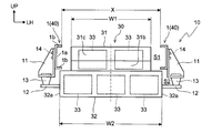
- the battery pack 30 is a relatively large and large-capacity secondary battery, and is arranged between a pair of side rails 1 in front of the drive device 50. As shown in FIG. 2, the battery pack 30 is housed in each of the first battery housing 31 and the second battery housing 32 and the first battery housing 31 and the second battery housing 32 arranged in the vehicle height direction. It also has a plurality of batteries 33.
- the first battery accommodating portion 31 of the present embodiment has a shape as if one corner of a rectangular parallelepiped is cut off (see FIG. 3). More specifically, the first battery accommodating portion 31 has a recess 31c in which the upper portion of the front surface 31b facing forward while mounted on the vehicle 20 is recessed in a rectangular parallelepiped shape. The first battery accommodating portion 31 is arranged in the first space S1 between the pair of side rails 1. On the other hand, the second battery accommodating portion 32 of the present embodiment has a rectangular parallelepiped shape. The second battery accommodating portion 32 is arranged in the second space S2 below the first space S1 and is continuous with the first battery accommodating portion 31.
- the first space S1 is a space hidden by the side rail 1 in the side view (vehicle width direction view) of the vehicle 20.
- the second space S2 is a space below the side rail 1 and is not hidden by the side rail 1 when viewed from the side of the vehicle 20.
- At least a part of the first battery accommodating portion 31 of the present embodiment is arranged in the first space S1, and at least a part of the first battery accommodating portion 31 overlaps with the side rail 1 in the side view of the vehicle 20.
- the entire second battery accommodating portion 32 of the present embodiment is arranged in the second space S2, and the entire portion does not overlap with each side rail 1 in the side view of the vehicle 20.
- the first battery accommodating portion 31 is mounted on the second battery accommodating portion 32.
- the first battery accommodating portion 31 and the second battery accommodating portion 32 are fixed to each other.
- the vehicle width direction dimension W2 of the second battery accommodation unit 32 is set larger than the vehicle width direction dimension W1 of the first battery accommodation unit 31.
- the vehicle width direction dimension W1 of the first battery accommodating portion 31 is smaller than the distance X between the pair of side rails 1 (W1 ⁇ X), and the vehicle width direction dimension W2 of the second battery accommodating portion 32 is the above distance.
- An example larger than X (W2> X) is shown.
- the distance X between the pair of side rails 1 is projected inward in the vehicle width direction from the upper and lower edges of the plate-shaped web 1a along the vehicle length direction and the vehicle height direction in each side rail 1.
- the distance is based on the tip (protruding end) of the flange 1b. Therefore, the above distance X corresponds to the length in the vehicle width direction between the right end of the flange 1b on the left side rail 1 and the left end of the flange 1b on the right side rail 1.
- the first battery accommodating portion 31 and the second battery accommodating portion 32 are arranged so that the center lines in the vehicle width direction (see the alternate long and short dash line in FIG. 2) coincide with each other.
- the battery pack 30 has a T-shape (inverted T-shape) that is upside down in front view (viewing in the direction of the vehicle length).
- the plurality of batteries 33 are connected in series and function as an energy source for driving the vehicle 20.
- the number and arrangement of the batteries 33 are not particularly limited, and can be appropriately changed according to the amount of electric power required to drive the vehicle 20, the dimensions and characteristics of the batteries 33, and the like.
- the battery pack 30 is connected to the side rail 1 via the support device 10.
- the support device 10 of the present embodiment elastically attaches the frame-side bracket 11 coupled to the ladder frame 40, the battery-side bracket 12 coupled to the battery pack 30, and the frame-side bracket 11 and the battery-side bracket 12 thereof. It has an elastic connecting portion 13 for connecting.
- the support device 10 elastically supports the battery pack 30 with respect to the rudder frame 40 by the configuration in which the frame side bracket 11 and the battery side bracket 12 are connected via the elastic connecting portion 13 in this way, and the rudder frame 40 The vibration transmitted from the battery pack 30 to the battery pack 30 is reduced.
- the support device 10 in which the frame side bracket 11, the battery side bracket 12, and the elastic connecting portion 13 are arranged three by three at intervals in the vehicle length direction on the left and right sides of the battery pack 30 is illustrated. (See FIGS. 1 and 3). Therefore, the battery pack 30 of the present embodiment is attached to the ladder frame 40 via the battery-side brackets 11 (six sets), the frame-side brackets 12, and the elastic connecting portions 13 provided in sixs each.
- the support device 10 of the present embodiment is formed symmetrically.
- Each frame side bracket 11 extends outward and downward in the vehicle width direction from the side rail 1.
- the upper portion of each frame side bracket 11 is arranged outside the web 1a of the side rail 1 in the vehicle width direction, and is connected to the side rail 1 by a fixture 14 such as a bolt.
- each battery-side bracket 12 projects from the end surface 32a on the outer side in the vehicle width direction of the second battery accommodating portion 32 to the outer side in the vehicle width direction.
- Each elastic connecting portion 13 is, for example, a rubber bush, and includes an elastic body having a substantially cylindrical shape or a substantially truncated cone shape.
- the elastic connecting portion 13 absorbs external force input in various directions (vehicle length direction, vehicle width direction, vehicle height direction, and a composite direction combining these directions).
- the elastic connecting portion 13 is fixed to each of the lower portion of the frame side bracket 11 and the outer end portion of the battery side bracket 12 in the vehicle width direction. As a result, the elastic connecting portion 13 elastically connects the frame-side bracket 11 and the battery-side bracket 12.
- the method of fixing the elastic connecting portion 13 is not particularly limited, and for example, a fixing tool such as a bolt may be used, or a method of matching the irregularities provided on each portion of the elastic connecting portion 13 is adopted. You may.
- the side rail 1 has a first region 3 including an overlapping portion 6 overlapping with the battery pack 30 in the side view of the vehicle 20, and a second region 4 adjacent to the first region 3 in the vehicle length direction. , 5 and are provided.
- the first region 3 is aligned with the battery pack 30 in the vehicle width direction, and the second regions 4 and 5 are located in front of or behind the battery pack 30.
- the overlapping portion 6 which is a part thereof overlaps with the battery pack 30 in a state of being mounted on the vehicle 20 (hereinafter, also referred to as “mounted state”) in a side view.
- the second regions 4 and 5 as a whole do not overlap with the battery pack 30 in the mounted state in a side view.
- the second regions 4 and 5 of the present embodiment are provided adjacent to both sides (front and rear) of the first region 3 in the vehicle length direction.
- one of the second regions 4 and 5 provided adjacent to the front of the first region 3 and located in front of the battery pack 30 is also referred to as a "front region 4" and is behind the first region 3.
- the other adjacent battery pack 30 located behind the battery pack 30 is also referred to as a "rear region 5".
- the first region 3 is also referred to as "overlapping region 3".
- the side rail 1 has a channel shape having a cross section (a cross section along the vehicle width direction and the vehicle height direction) of the above-mentioned web 1a and flange 1b in any of the overlapping region 3, the front region 4, and the rear region 5. Make up.
- the height dimension L1 of the overlapping region 3 of the present embodiment is any of the height dimensions L2 and L3 of the front region 4 and the rear region 5. Less than (L1 ⁇ L2 and L1 ⁇ L3). However, the height dimension L1 of the overlapping region 3 is not constant (uniform), and is larger at the end portions 3a and 3b than at the intermediate portion 3c in the vehicle height direction. On the other hand, the height dimension L2 of the front region 4 is constant, and the height dimension L3 of the rear region 5 is also constant.
- the term "constant” here does not have to be strictly defined as one value, and errors that may occur in design and manufacturing are allowed.
- the heights of the lower end 7L of the overlapping region 3, the lower end 8L of the front region 4, and the lower end 9L of the rear region 5 in the vehicle height direction (hereinafter, also referred to as “height position”) will be described in detail.
- the side rail 1 of the present embodiment has a channel shape as described above, the lower ends 7L, 8L, and 9L here correspond to the lower surface (the surface facing downward) of the lower flange 1b at the corresponding portion. do.
- the lower end 7L of the overlapping region 3 (hereinafter, also referred to as “overlapping lower end 7L”) corresponds to the lower surface of the lower flange 1b in the overlapping region 3.
- the lower end 8L of the front region 4 corresponds to the lower surface of the lower flange 1b in the front region 4, and the lower end 9L of the rear region 5 (hereinafter, “rear lower end 9L”). (Also referred to as) corresponds to the lower surface of the lower flange 1b in the rear region 5.
- the overlapping lower end 7L is higher (located above) in the vehicle height direction than either the front lower end 8L or the rear lower end 9L. Therefore, the distance D1 between the overlapping lower end 7L and the ground G is longer than any of the distance D2 between the front lower end 8L and the ground G and the distance D3 between the rear lower end 9L and the ground G. As described above, a large space for moving the battery pack 30 is secured below the overlapping region 3 as compared with below the front region 4 and the rear region 5.
- the height position of the overlapping lower end 7L of the present embodiment is different between the end portions 3a and 3b in the vehicle length direction and the intermediate portion 3c in the overlapping region 3.
- the front end portion 3a is also referred to as “overlapping front end portion 3a”
- the rear end portion 3b is also referred to as “overlapping rear end portion 3b”.
- the symbol "7a” is attached to the lower end of the overlapping front end portion 3a
- the symbol “7b” is attached to the lower end of the overlapping rear end portion 3b
- the symbol “7c” is attached to the lower end of the intermediate portion 3c.
- the intermediate portion 3c is a portion between the overlapping front end portion 3a and the overlapping rear end portion 3b.
- the lower end 7a of the overlapping front end 3a is continuous from the front lower end 8L and is inclined upward toward the rear. As described above, the lower end 7a of the overlapping front end portion 3a becomes higher in the vehicle height direction so as to be separated from the lower end 8L of the front region 4 adjacent to the overlapping front end portion 3a. Further, the lower end 7b of the overlapping rear end portion 3b is continuous from the rear lower end 9L and is inclined upward toward the front. As described above, the lower end 7b of the overlapping rear end portion 3b becomes higher in the vehicle height direction so as to be separated from the lower end 9L of the rear region 5 adjacent to the overlapping rear end portion 3b.
- the lower ends 7a and 7b of the overlapping front end portion 3a and the overlapping rear end portion 3b have a function of suppressing a sudden change in the cross section in the overlapping region 3.
- the lower end 7c of the intermediate portion 3c is continuous from the lower ends 7a and 7b of the overlapping front end portion 3a and the overlapping rear end portion 3b, and the height position is constant. Therefore, in the overlapping region 3, the lower end 7c of the intermediate portion 3c extends in a straight line along the vehicle length direction above the lower ends 7a and 7b of the overlapping front end portion 3a and the overlapping rear end portion 3b.
- the front lower end 8L and the rear lower end 9L each have a constant height position, and extend in a straight line along the vehicle length direction below the overlapping lower end 7L.
- the height positions of the upper end 7U of the overlapping region 3, the upper end 8U of the front region 4, and the upper end 9U of the rear region 5 will be described in detail.
- the side rail 1 of the present embodiment has a channel shape as described above, the upper ends 7U, 8U, and 9U here correspond to the upper surface (the surface facing upward) of the upper flange 1b at the corresponding portion. ..
- the upper end 7U of the overlapping region 3 (hereinafter, also referred to as “overlapping upper end 7U”) corresponds to the upper surface of the upper flange 1b in the overlapping region 3.
- front upper end 8U corresponds to the upper surface of the upper flange 1b in the front region 4
- rear upper end 9U corresponds to the upper surface of the upper flange 1b in the rear region 5.
- the height positions of the overlapping upper end 7U, the front upper end 8U, and the rear upper end 9U are all constant. Therefore, the overlapping upper end 7U, the front upper end 8U, and the rear upper end 9U extend in a straight line along the vehicle length direction above the overlapping lower end 7L, the front lower end 8L, and the rear lower end 9L.
- the upper end of the overlapping front end portion 3a is designated by the symbol "7d”
- the upper end of the overlapping rear end portion 3b is designated by the symbol "7e”
- the upper end of the intermediate portion 3c is designated by the symbol "7f”. Is attached.
- the upper end 7d of the overlapping front end portion 3a is flush with the upper end 8U of the front region 4 adjacent to the overlapping front end portion 3a.
- the upper end 7e of the overlapping rear end 3b is flush with the upper end 9U of the rear region 5 adjacent to the overlapping rear end 3b.
- the mounted battery pack 30 is provided with the height position of the upper surface (upper surface of the first battery accommodating portion 31) 31a higher than the overlapping lower end 7L.
- the battery pack 30 in which the height position of the upper surface 31a is set higher than the overlapping lower end 7L and lower than the overlapping upper end 7U is illustrated.
- the height position of the upper surface 31a of the mounted battery pack 30 may be higher than the height position of the overlapping lower end 7L, and for example, the height position of the upper surface 31a may be set to be equal to or higher than the height position of the overlapping upper end 7U.
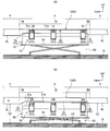
- the procedure for removing the battery pack 30 will be described. As shown in FIG. 4A, the lifter 60 is arranged below the battery pack 30, and the support surface 61 thereof is raised to support the battery pack 30 from below. Next, the fixture 14 is removed, and the battery pack 30 and the support device 10 are integrally separated from the side rail 1. As a result, the battery pack 30 can move relative to the side rail 1 together with the support device 10.
- the support surface 61 of the lifter 60 is lowered, and the battery pack 30 and the support device 10 are integrally lowered.
- the lifter 60 on which the battery pack 30 is placed is moved in the vehicle width direction to cover the overlapping area 3.
- the battery pack 30 and the support device 10 are taken out from the side rail 1 to the outside in the vehicle width direction through the space below.
- the overlap region 3 is larger in the vehicle height direction than the front region 4 and the rear region 5. Space is secured. Therefore, when the battery pack 30 is taken out through the space below the overlapping region 3, the upper surface 31a of the battery pack 30 is located lower than the overlapping lower end 7L even if it is higher than the front lower end 8L and the rear lower end 9L. If so, the battery pack 30 can be taken out.
- the overlapping lower end 7L is higher in the vehicle height direction than the front lower end 8L and the rear lower end 9L, the overlapping lower end 7L is at the same height position as the front lower end 8L or the rear lower end 9L. In comparison, interference between the overlapping lower end 7L and the battery pack 30 is more likely to be avoided.
- the battery pack 30 can be attached by reversing the removal procedure described above.
- the battery pack 30 and the support device 10 on the lifter 60 are moved from the outside to the inside in the vehicle width direction of the overlapping area 3 through the space below the overlapping area 3.
- the side rail 1 since the overlapping lower end 7L is higher in the vehicle height direction than the front lower end 8L and the rear lower end 9L as described above, interference between the overlapping lower end 7L and the battery pack 30 can be easily avoided.
- each frame side bracket 11 is connected to the side rail 1 by the fixture 14. Finally, the lifter 60 is lowered again and moved to the outside of the vehicle 20.
- a larger space (dimension in the vehicle height direction) for moving the battery pack 30 is secured below the overlapping region 3 than below the front region 4 and the rear region 5.
- the overlapping lower end 7L and the battery pack 30 are compared with the case where the overlapping lower end 7L is at the same height as the front lower end 8L or the rear lower end 9L. It becomes easier to avoid interference with.
- the battery pack 30 is moved through the space below the overlapping area 3 while avoiding interference between the overlapping lower end 7L and the battery pack 30 without having to lift the side rail 1 and the ladder frame 40 including the side rail 1. It becomes possible. Therefore, the work process of attaching and detaching the battery pack 30 can be simplified. Further, since the equipment for lifting the side rail 1 and the entire rudder frame 40 is not required, the equipment cost for attaching and detaching the battery pack 30 can be suppressed.
- the size limitation of the battery pack 30 can be relaxed by easily avoiding the interference between the overlapping lower end 7L and the battery pack 30 as described above. Therefore, by increasing the capacity (battery capacity) of the battery pack 30, it contributes to the extension of the cruising range of the vehicle 20.
- the battery pack 30 of the present embodiment has a relatively large height dimension (dimension in the vehicle height direction in the mounted state) because it includes the first battery accommodating portion 31 and the second battery accommodating portion 32. Therefore, even in such attachment and detachment of the battery pack 30, interference with the battery pack 30 can be easily avoided.
- the time required for replacing the battery pack 30 can be shortened. Therefore, when the charge amount of the battery pack 30 decreases, the battery pack 30 can be replaced with a fully charged battery pack in a short time. Therefore, it also contributes to securing the operating time of the vehicle 20.
- the overlapping area 3 can be made into a simpler shape as compared with the case where the height position of the overlapping upper end 7U is not constant. This makes it easy to place another device (eg, packing box 22) on the overlapping area 3.
- the height positions of the overlapping upper end 7U, the front upper end 8U, and the rear upper end 9U are constant, and these upper ends 7U, 8U, and 9U extend in a straight line along the vehicle length direction.
- the entire rail 1 can be made into a simpler shape. As a result, it becomes easy to arrange another device on the side rail 1 over the entire area in the vehicle length direction.
- connection part can be made into a simple shape. As a result, it becomes easy to arrange another device on each connection portion between the overlapping region 3 and the front region 4 and the rear region 5.
- the side rail 1 since the side rail 1 is configured as described above, the work process can be simplified and the equipment cost can be suppressed in the attachment and detachment of the battery pack 30.
- the vehicle 20 is provided with a plurality of cross members 2 constituting the rudder frame 40 together with the side rail 1. Even in the vehicle 20 provided with such a ladder frame 40, the side rail 1 can simplify the work process in attaching and detaching the battery pack 30 as described above, and can suppress the equipment cost.
- the side rail 1'of the second embodiment has a height dimension L1'of the overlapping region 3', the front region 4', and the rear region 5'with respect to the side rail 1 of the first embodiment. , L2', L3'are different.
- L1'of the overlapping region 3', the front region 4', and the rear region 5'with respect to the side rail 1 of the first embodiment L2', L3'are different.
- the same or corresponding elements as those described in the first embodiment are designated by the same reference numerals, and duplicate description will be omitted.
- the terms "equal” here do not have to be exactly the same, and errors that may occur in design and manufacturing are acceptable.
- the lower ends 7L, 8L, and 9L are the same as those of the first embodiment, whereas the upper ends 7U', 8U', and 9U are the same.
- the height position of ′ is not constant, and extends parallel to the corresponding lower ends 7L, 8L, and 9L, respectively. Therefore, the overlapping upper end 7U'of this embodiment is higher (located above) in the vehicle height direction than either the front upper end 8U' or the rear upper end 9U'.
- the height position of the upper end 7U' is different between the front end portion 3a', the rear end portion 3b', and the intermediate portion 3c'.
- the upper end 7d'of the overlapping front end 3a' is continuous from the front upper end 8U' and is inclined upward toward the rear.
- the upper end 7e'of the overlapping rear end portion 3b' is continuous from the rear upper end 9U' and is inclined upward toward the front.
- the upper ends 7d ′ and 7e ′ of the overlapping front end portion 3a ′ and the overlapping rear end portion 3b ′ have a function of suppressing a sudden change in the cross section in the overlapping region 3 ′.
- the upper end 7f'of the intermediate portion 3c' is continuous from the upper ends 7d' and 7e' of the overlapping front end portion 3a'and the overlapping rear end portion 3b', and the height position is constant. Therefore, in the overlapping region 3'of the present embodiment, the upper end 7f'of the intermediate portion 3c'is above the upper ends 7d'and 7e' of the overlapping front end portion 3a'and the overlapping rear end portion 3b'in the vehicle length direction. It extends in a straight line along.
- the front upper end 8U'and the rear upper end 9U' have constant height positions, and extend in a straight line along the vehicle length direction below the overlapping upper end 7U'.
- the height dimension L1'of the overlapping region 3' is the same as the height dimensions L2'and L3'of the front region 4'and the rear region 5', the front region 4'and the rear region 3'are also the same. It is possible to secure the same strength and rigidity as the region 5'. Thereby, the deformation of the overlapping region 3'can be further suppressed.
- the side rail 1'of the present embodiment and the vehicle (electric vehicle) provided with the side rail 1' the same operation and effect can be obtained from the same configuration as that of the above embodiment.
- the above battery pack 30 is an example.
- the side rails 1, 1' may be arranged outside the battery pack 30'shown in FIG. 6 in the vehicle width direction instead of the battery pack 30 described above.
- FIG. 6 illustrates the side rail 1 of the first embodiment, the side rail 1'of the second embodiment can also be applied in the same manner.
- the same or corresponding elements as those described in the first embodiment are designated by the same reference numerals, and duplicate description will be omitted.
- the battery pack 30'of this modification has the shape of the first battery accommodating portion 31'and the dimension W2'in the vehicle width direction of the second battery accommodating portion 32'with respect to the battery pack 30 shown in the first embodiment. Is different. Specifically, in the battery pack 30', the first battery accommodating portion 31'has a rectangular parallelepiped shape (the recess 31c described above is omitted), and the vehicle width direction dimension W2'of the second battery accommodating portion 32'is It is set to be the same as the vehicle width direction dimension W1 of the first battery accommodating portion 31'.
- the first battery accommodating portion 31'and the second battery accommodating portion 32' are arranged so that the center lines in the vehicle width direction (see the alternate long and short dash line in FIG. 6) coincide with each other.
- the battery pack 30' forms a rectangular shape when viewed from the front (viewed in the direction of the vehicle length).
- the shape is simplified as compared with the battery pack 30 of each of the above embodiments.
- the specific shape and dimensions of the battery pack arranged between the side rails 1 and 1' are not particularly limited.
- the height dimension can be increased by omitting the above-mentioned second battery accommodating portions 32 and 32'. It may be reduced.
- the overlapping lower end 7L of the side rails 1, 1's may be higher in the vehicle height direction than the front lower end 8L and the rear lower end 9L, and the specific height position is not particularly limited.
- the height positions of the overlapping front end portions 3a, 3a'and the lower ends 7a, 7b of the overlapping rear end portions 3b, 3b' may be constant.
- the entire overlapping lower end 7L including the lower end 7c of the intermediate portions 3c and 3c' may be inclined up or down toward the front or the rear.
- the configuration of the support device 10 described above is an example.
- the vehicle 20 to which the side rails 1, 1'are applied is not limited to the electric vehicle provided with only the motor unit 51 as a drive source, but may be a hybrid vehicle further provided with an engine.
- the side rails 1, 1' can be applied to a vehicle not provided with the rudder frame 40, and may be applied to a commercial vehicle other than a truck.
- the above configuration of the side rails 1, 1' may be applied to only one of the side rails arranged on both sides of the battery packs 30 and 30'in the vehicle width direction in the vehicle 20.
Landscapes
- Engineering & Computer Science (AREA)
- Chemical & Material Sciences (AREA)
- Combustion & Propulsion (AREA)
- Transportation (AREA)
- Mechanical Engineering (AREA)
- Body Structure For Vehicles (AREA)
- Arrangement Or Mounting Of Propulsion Units For Vehicles (AREA)
Abstract
La présente invention vise à supprimer les coûts d'équipement tout en simplifiant un processus de travail dans la fixation et le détachement d'un bloc-batterie. À cet effet, dans un véhicule, un rail latéral 1 disposé sur le côté externe dans la direction de la largeur du véhicule d'un bloc-batterie 30 comprend : une première région 3 comprenant une partie de chevauchement 6 qui chevauche le bloc-batterie 30 lorsqu'elle est vue dans la direction de la largeur du véhicule; et des secondes régions 4, 5 adjacentes à la première région 3 dans la direction de la longueur du véhicule. L'extrémité inférieure 7L de la première région 3 est plus haute dans la direction de la hauteur du véhicule que les extrémités inférieures 8L, 9L des secondes régions 4, 5.
Applications Claiming Priority (2)
| Application Number | Priority Date | Filing Date | Title |
|---|---|---|---|
| JP2020-014252 | 2020-01-31 | ||
| JP2020014252A JP7381355B2 (ja) | 2020-01-31 | 2020-01-31 | サイドレール及び電動車両 |
Publications (1)
| Publication Number | Publication Date |
|---|---|
| WO2021153065A1 true WO2021153065A1 (fr) | 2021-08-05 |
Family
ID=77078974
Family Applications (1)
| Application Number | Title | Priority Date | Filing Date |
|---|---|---|---|
| PCT/JP2020/046986 WO2021153065A1 (fr) | 2020-01-31 | 2020-12-16 | Rail latéral et véhicule électrique |
Country Status (2)
| Country | Link |
|---|---|
| JP (1) | JP7381355B2 (fr) |
| WO (1) | WO2021153065A1 (fr) |
Families Citing this family (1)
| Publication number | Priority date | Publication date | Assignee | Title |
|---|---|---|---|---|
| JP7360834B2 (ja) * | 2019-07-12 | 2023-10-13 | メルセデス・ベンツ グループ アクチェンゲゼルシャフト | 電動トラック |
Citations (2)
| Publication number | Priority date | Publication date | Assignee | Title |
|---|---|---|---|---|
| JPS6353887U (fr) * | 1986-09-27 | 1988-04-11 | ||
| KR20070106125A (ko) * | 2006-04-28 | 2007-11-01 | 서진산업 주식회사 | 하이브리드형 차량용 샤시 프레임 |
Family Cites Families (2)
| Publication number | Priority date | Publication date | Assignee | Title |
|---|---|---|---|---|
| JP5966824B2 (ja) * | 2012-09-28 | 2016-08-10 | 三菱自動車工業株式会社 | トラック形電動車両のフレーム構造 |
| JP7057712B2 (ja) * | 2018-04-27 | 2022-04-20 | ダイムラー・アクチェンゲゼルシャフト | 車両用バッテリパックの支持装置 |
-
2020
- 2020-01-31 JP JP2020014252A patent/JP7381355B2/ja active Active
- 2020-12-16 WO PCT/JP2020/046986 patent/WO2021153065A1/fr active Application Filing
Patent Citations (2)
| Publication number | Priority date | Publication date | Assignee | Title |
|---|---|---|---|---|
| JPS6353887U (fr) * | 1986-09-27 | 1988-04-11 | ||
| KR20070106125A (ko) * | 2006-04-28 | 2007-11-01 | 서진산업 주식회사 | 하이브리드형 차량용 샤시 프레임 |
Also Published As
| Publication number | Publication date |
|---|---|
| JP7381355B2 (ja) | 2023-11-15 |
| JP2021120260A (ja) | 2021-08-19 |
Similar Documents
| Publication | Publication Date | Title |
|---|---|---|
| CN112292278B (zh) | 车辆用电池组支撑装置 | |
| US11623513B2 (en) | Electric drive axle in a vehicle | |
| EP3778278B1 (fr) | Véhicule comportant un dispositif de support d'un bloc de batteries | |
| WO2019230286A1 (fr) | Véhicule à entraînement électrique | |
| CN112606670A (zh) | 车辆的高压电池单元及车辆的车身底部 | |
| JP2021088343A (ja) | 電気車両の駆動システム | |
| US11975600B2 (en) | Electric truck | |
| JP7477686B2 (ja) | 電動トラック用フレーム | |
| WO2021106391A1 (fr) | Dispositif de support pour bloc-batterie destiné à un véhicule | |
| WO2021090554A1 (fr) | Dispositif de support pour bloc-batterie de véhicule, et véhicule électrique | |
| WO2021153065A1 (fr) | Rail latéral et véhicule électrique | |
| JP2020001527A (ja) | 車両用バッテリパック支持装置 | |
| JP2021075111A (ja) | 車両用バッテリパックの支持装置 | |
| CN112519894A (zh) | 车辆下部构造 | |
| JP2020001554A (ja) | 車両用バッテリパック支持装置 | |
| WO2021145056A1 (fr) | Structure d'agencement d'unité de source d'alimentation dans un véhicule électrique | |
| JP2021017181A (ja) | 車両用バッテリの支持装置 | |
| JP2019217908A (ja) | 車両用バッテリパック支持装置 | |
| WO2022191264A1 (fr) | Châssis | |
| JP7358323B2 (ja) | 電動トラック | |
| JP2022025814A (ja) | 車両用バッテリパックの支持装置 | |
| JP2021011138A (ja) | 車両用バッテリの支持装置 | |
| CN117842183A (zh) | 车身框架结构 | |
| JP2022085063A (ja) | バッテリパック支持装置 | |
| JP2022085507A (ja) | 車両の下部構造 |
Legal Events
| Date | Code | Title | Description |
|---|---|---|---|
| 121 | Ep: the epo has been informed by wipo that ep was designated in this application |
Ref document number: 20916503 Country of ref document: EP Kind code of ref document: A1 |
|
| NENP | Non-entry into the national phase |
Ref country code: DE |
|
| 122 | Ep: pct application non-entry in european phase |
Ref document number: 20916503 Country of ref document: EP Kind code of ref document: A1 |