WO2021100079A1 - 内視鏡用キャップ、内視鏡用処置具および内視鏡システム - Google Patents
内視鏡用キャップ、内視鏡用処置具および内視鏡システム Download PDFInfo
- Publication number
- WO2021100079A1 WO2021100079A1 PCT/JP2019/045049 JP2019045049W WO2021100079A1 WO 2021100079 A1 WO2021100079 A1 WO 2021100079A1 JP 2019045049 W JP2019045049 W JP 2019045049W WO 2021100079 A1 WO2021100079 A1 WO 2021100079A1
- Authority
- WO
- WIPO (PCT)
- Prior art keywords
- endoscope
- hood portion
- tip
- hood
- cap
- Prior art date
- Legal status (The legal status is an assumption and is not a legal conclusion. Google has not performed a legal analysis and makes no representation as to the accuracy of the status listed.)
- Ceased
Links
Images






Classifications
-
- A—HUMAN NECESSITIES
- A61—MEDICAL OR VETERINARY SCIENCE; HYGIENE
- A61B—DIAGNOSIS; SURGERY; IDENTIFICATION
- A61B1/00—Instruments for performing medical examinations of the interior of cavities or tubes of the body by visual or photographical inspection, e.g. endoscopes; Illuminating arrangements therefor
- A61B1/00131—Accessories for endoscopes
- A61B1/00137—End pieces at either end of the endoscope, e.g. caps, seals or forceps plugs
-
- A—HUMAN NECESSITIES
- A61—MEDICAL OR VETERINARY SCIENCE; HYGIENE
- A61B—DIAGNOSIS; SURGERY; IDENTIFICATION
- A61B1/00—Instruments for performing medical examinations of the interior of cavities or tubes of the body by visual or photographical inspection, e.g. endoscopes; Illuminating arrangements therefor
- A61B1/00064—Constructional details of the endoscope body
- A61B1/00071—Insertion part of the endoscope body
- A61B1/0008—Insertion part of the endoscope body characterised by distal tip features
- A61B1/00087—Tools
-
- A—HUMAN NECESSITIES
- A61—MEDICAL OR VETERINARY SCIENCE; HYGIENE
- A61B—DIAGNOSIS; SURGERY; IDENTIFICATION
- A61B1/00—Instruments for performing medical examinations of the interior of cavities or tubes of the body by visual or photographical inspection, e.g. endoscopes; Illuminating arrangements therefor
- A61B1/00064—Constructional details of the endoscope body
- A61B1/00071—Insertion part of the endoscope body
- A61B1/0008—Insertion part of the endoscope body characterised by distal tip features
- A61B1/00089—Hoods
-
- A—HUMAN NECESSITIES
- A61—MEDICAL OR VETERINARY SCIENCE; HYGIENE
- A61B—DIAGNOSIS; SURGERY; IDENTIFICATION
- A61B1/00—Instruments for performing medical examinations of the interior of cavities or tubes of the body by visual or photographical inspection, e.g. endoscopes; Illuminating arrangements therefor
- A61B1/00064—Constructional details of the endoscope body
- A61B1/00071—Insertion part of the endoscope body
- A61B1/0008—Insertion part of the endoscope body characterised by distal tip features
- A61B1/00098—Deflecting means for inserted tools
-
- A—HUMAN NECESSITIES
- A61—MEDICAL OR VETERINARY SCIENCE; HYGIENE
- A61B—DIAGNOSIS; SURGERY; IDENTIFICATION
- A61B1/00—Instruments for performing medical examinations of the interior of cavities or tubes of the body by visual or photographical inspection, e.g. endoscopes; Illuminating arrangements therefor
- A61B1/00064—Constructional details of the endoscope body
- A61B1/00071—Insertion part of the endoscope body
- A61B1/0008—Insertion part of the endoscope body characterised by distal tip features
- A61B1/00101—Insertion part of the endoscope body characterised by distal tip features the distal tip features being detachable
-
- A—HUMAN NECESSITIES
- A61—MEDICAL OR VETERINARY SCIENCE; HYGIENE
- A61B—DIAGNOSIS; SURGERY; IDENTIFICATION
- A61B1/00—Instruments for performing medical examinations of the interior of cavities or tubes of the body by visual or photographical inspection, e.g. endoscopes; Illuminating arrangements therefor
- A61B1/00131—Accessories for endoscopes
- A61B1/0014—Fastening element for attaching accessories to the outside of an endoscope, e.g. clips, clamps or bands
-
- A—HUMAN NECESSITIES
- A61—MEDICAL OR VETERINARY SCIENCE; HYGIENE
- A61B—DIAGNOSIS; SURGERY; IDENTIFICATION
- A61B17/00—Surgical instruments, devices or methods
- A61B17/28—Surgical forceps
- A61B17/29—Forceps for use in minimally invasive surgery
-
- A—HUMAN NECESSITIES
- A61—MEDICAL OR VETERINARY SCIENCE; HYGIENE
- A61B—DIAGNOSIS; SURGERY; IDENTIFICATION
- A61B2560/00—Constructional details of operational features of apparatus; Accessories for medical measuring apparatus
- A61B2560/04—Constructional details of apparatus
Definitions
- the present invention relates to an endoscopic cap, an endoscopic treatment tool, and an endoscopic system.
- ESD endoscopic submucosal dissection
- a traction device is used to apply tension to the submucosa during exfoliation (see, eg, Patent Documents 1 and 2).
- the traction device described in Patent Documents 1 and 2 is a cap type attached to the tip end portion of the endoscope, and supports the gripping device so as to be movable in the longitudinal direction.
- the longitudinal advance and retreat of the grip device causes the grip at the tip of the grip device to descend and rise in front of the endoscope. Therefore, the mucous membrane can be grasped and lifted by the grasping device in the field of view of the endoscope.
- the lowering position of the grip portion is far from the tip of the endoscope and far from the focal position of the endoscope.
- the lowering position of the grip portion is close to the tip of the endoscope.
- the mucous membrane raised by the grip portion is pulled toward the proximal end side of the endoscope by retracting the grip device. At this time, it is desirable that the mucous membrane can be pulled in to a position closer to the proximal end.
- the present invention has been made in view of the above circumstances, and the grip portion can be lowered to a position close to the tip of the endoscope, and the amount of drawing of the biological tissue gripped by the grip portion is secured. It is an object of the present invention to provide an endoscopic cap, an endoscopic treatment tool, and an endoscopic system that can be used.
- a tubular hood portion attached to the outer peripheral surface of the tip portion of the endoscope is connected to the tip of the hood portion, and the tip portion of the endoscope is inserted into the hood portion.
- a cap portion that has an abutting surface to which the tip of the endoscope is abutted in the state of being abutted, and that projects from the tip of the hood portion in the longitudinal direction of the hood portion, and a channel tube into which a long device is inserted.
- the tip of the channel tube is fixed to the base end of the hood, and the channel tube extends substantially parallel to the longitudinal axis of the hood, and a linear shape for connecting the device to the hood.
- a connecting member including a connecting member that is supported by the hood portion and extends along the outer peripheral surface of the hood portion, and the tip of the channel tube is closer to the base end side of the hood portion than the abutting surface.
- the hood portion is provided at a position separated from each other in the circumferential direction of the hood portion, and has a pair of support holes into which the connecting member is inserted from the outside to the inside of the hood portion.
- the connecting member can swing with respect to the hood portion with each of the support holes as a fulcrum, and the pair of support holes are closer to the base end side of the hood portion than the abutting surface and the channel.
- the device is inserted into the channel tube, and the device is connected to the hood portion by a connecting member extending between a pair of support holes in the hood portion. Then, the hood portion is attached to the tip portion of the endoscope so that the pair of support holes are arranged in the left-right direction of the endoscope and the channel tube and the device are arranged on the upper side of the endoscope. The tip of the endoscope abutted against the contact surface is positioned at a predetermined position with respect to the hood portion.
- the device when the device is moved forward in the longitudinal direction with respect to the hood portion and the endoscope, the device swings around the support hole as a fulcrum together with the connecting member, and the grip portion at the tip of the device is the tip of the endoscope. It descends forward. Further, when the device is moved rearward in the longitudinal direction with respect to the hood portion and the endoscope, the device swings around the support hole as a fulcrum together with the connecting member, and the grip portion rises in front of the tip of the endoscope. Therefore, by simply pushing the device forward, the gripping portion can be brought close to the target portion of the biological tissue located in the lower portion in the field of view of the endoscope, and the target portion can be gripped by the gripping portion. Further, by simply pulling the device backward, the target portion gripped by the grip portion can be raised and pulled toward the proximal end side of the tip of the hood portion.
- a pair of support holes which are the swing centers of the grip portion, are provided at a position closer to the base end side than the abutting surface on which the tip end of the endoscope is arranged.
- the grip portion can be lowered to a position closer to the tip of the endoscope as compared with the case where the pair of support holes are provided in the cap portion, and the living tissue gripped by the grip portion can be pulled in. The amount can be secured.
- the inner peripheral surface of the hood portion may have a tapered surface whose inner diameter gradually increases from the tip end to the base end.
- one of the hood portion and the cap portion has a pair of fixing holes that are separated from each other in the circumferential direction and are provided at positions different from the pair of support holes, and the connecting member. Both ends of the above may be fixed in the pair of fixing holes. According to this configuration, by providing a fixing hole for fixing the end portion of the connecting member separately from the support hole, it is possible to prevent a force from being applied to the end portion of the connecting member when the connecting member swings.
- the pair of fixing holes may be provided in the cap portion or may be provided in the hood portion.
- a knot having an outer diameter larger than the diameter of the support hole may be formed at both ends of the connecting member, and both ends of the connecting member may be fixed by the pair of support holes. ..
- the connecting member may be a soft thread. According to this configuration, the degree of freedom of movement of the grip portion can be improved as compared with the case where a member having high bending rigidity such as a metal wire is used as the connecting member.
- Another aspect of the present invention comprises a long gripping device and an endoscopic cap according to any one of the above, the length of which the gripping device movably penetrates the channel tube in the longitudinal direction.
- a flexible elongated member of the shaku a grip portion connected to the tip of the elongated member to grip the biological tissue, and a connector provided on the proximal end side of the grip portion and arranged on the distal end side of the channel tube.
- the connector has a through hole penetrating in a direction intersecting the longitudinal direction of the elongated member, and the connecting member extends between the pair of support holes via the inside of the through hole. It is a treatment tool for endoscopy.
- Another aspect of the present invention is an endoscopic system comprising an endoscope and the above-mentioned endoscopic treatment tool.
- a notch may be formed in a part of the hood portion, and a tape for adhering the hood portion and the endoscope may be provided along the edge of the notch.
- the connector may be provided on the side opposite to the hood portion with respect to the elongated member in the radial direction of the hood portion. According to this configuration, it is possible to prevent the swinging connector from interfering with the surface of the hood portion.
- the connector may be located between the elongated member and the hood portion in the radial direction of the hood portion. According to this configuration, it is possible to prevent the connecting member from being entangled with the gripping device.
- the edge of the tip of the cap has a protrusion extending from the base end of the cap portion toward the tip and a recess extending from the tip of the cap portion toward the base end.
- the connecting member may be configured to swing from a first position extending along the outer peripheral surface of the hood portion to a second position in contact with the protrusion of the cap portion.
- the edge of the tip of the cap has a protrusion extending from the base end of the cap portion toward the tip and a recess extending from the tip of the cap portion toward the base end.
- the gripping portion can be lowered to a position close to the tip of the endoscope, and the amount of drawing of the biological tissue gripped by the gripping portion can be secured.
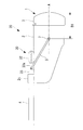
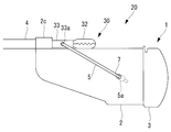
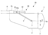
- FIG. 1A It is a side view which shows the structure of the endoscope cap, the endoscope treatment tool and the endoscope system which concerns on one Embodiment of this invention. It is a figure explaining the operation of the treatment tool for an endoscope of FIG. 1A, and is the figure which shows the state which the grip part is lowered to the lowering position. It is a figure which shows an example of the fixing tape for fixing a hood part to an endoscope. It is a figure which shows the state which fixed the hood part to an endoscope by using the fixing tape of FIG. 2A. It is a figure which shows an example of the fixing tape for fixing a channel tube to an endoscope.
- FIG. 2C It is a figure which shows the state which fixed the channel tube to an endoscope using the fixing tape of FIG. 2C. It is the top view which looked at the cap for an endoscope from the upper side. It is a perspective view of the cap for an endoscope, and is the figure which shows the state which the grip part was lowered to the lowering position. It is a figure which shows an example of the use method of the endoscope system, and is the figure which shows the state of gripping a living tissue by the gripping portion at a descending position. It is a figure which shows an example of the use method of the endoscope system, and is the figure which shows the state of raising and pulling a living tissue by a gripping part.
- the endoscope system 100 includes an endoscope 10 and an endoscope treatment tool 20.
- the endoscope treatment tool 20 includes a gripping device 30 and an endoscope cap 1 that supports the gripping device 30 and is attached to the tip of the endoscope 10.
- the gripping device 30 includes a long and flexible elongated member 31, a gripping portion 32 connected to the tip of the elongated member 31 to grip the biological tissue, and a connector 33 provided on the proximal end side of the gripping portion 32.
- the elongated member 31 is, for example, a coil sheath.
- the grip portion 32 has a pair of grip pieces that can be opened and closed, and can grip the biological tissue between the pair of grip pieces.
- the connector 33 is provided between, for example, the elongated member 31 and the grip portion 32, and has a through hole 33a penetrating in a direction orthogonal to the longitudinal direction of the elongated member 31.
- the endoscope cap 1 is a base of a substantially cylindrical hood portion 2 mounted on the outer peripheral surface of the tip portion of the endoscope 10, a cap portion 3 connected to the tip of the hood portion 2, and a hood portion 2.
- the channel tube 4 fixed to the end portion, the connecting member 5 supported by the hood portion 2 and connecting the hood portion 2 and the gripping device 30, and the tip 10a of the endoscope 10 are placed at or near the tip of the hood portion 2. It is provided with an abutting surface 6 for positioning at a predetermined position.
- the endoscope cap 1 has a vertical direction and a horizontal direction that are orthogonal to each other.
- the vertical direction and the horizontal direction are the radial directions of the hood portion 2, respectively, and the arrangement direction of the longitudinal axis of the hood portion 2 and the longitudinal axis of the channel tube 4 is the vertical direction.
- the vertical and horizontal directions of the endoscope cap 1 correspond to the vertical and horizontal directions of the endoscope 10, respectively.
- the hood portion 2 is opened at the tip end surface and the proximal end surface, and the distal end portion of the endoscope 10 is inserted from the proximal end side.
- the hood portion 2 is fitted to the outer peripheral surface of the tip portion of the endoscope 10, and the tip of the endoscope 10 is caused by friction between the inner peripheral surface of the hood portion 2 and the outer peripheral surface of the tip portion of the endoscope 10. It is fixed to the part.
- the inner peripheral surface of the hood portion 2 has a tapered surface 2a whose inner diameter gradually increases from the tip end to the base end.
- FIG. 2A is a bottom view of the hood portion 2 and the endoscope 10 as viewed from below. Further, the endoscope 10 and the channel tube 4 may be fixed as shown in FIG. 2D by using a fixing tape 11b having a shape as shown in FIG. 2C.
- the hood portion 2 is provided with a notch 2b which is a portion largely cut out from the base end to the tip end.
- the edge of the notch 2b and the outer peripheral surface of the endoscope 10 exposed from the notch 2b are covered with the fixing tape 11a.
- a large adhesion range (the length of the edge of the hood portion 2) is secured between the endoscope 10 and the hood portion 2, and the hood portion 2 and the outer peripheral surface of the endoscope portion 10 are firmly adhered to each other. Can be done. Therefore, for example, even when the curved portion of the endoscope 10 is curved, the hood portion 2 is unlikely to fall off from the endoscope 10.
- the method of adhering the endoscope 10 and the hood portion 2 with the fixing tape 11a is not limited to this embodiment, and can be adopted even when the gripping device 30 is changed to a snare or a knife, for example.
- the hood portion 2 has a pair of support holes 7 for supporting the connecting member 5.
- the pair of support holes 7 are provided at positions that are separated from each other in the circumferential direction of the hood portion 2 and face each other in the left-right direction.
- Each support hole 7 penetrates from the outer peripheral surface to the inner peripheral surface of the hood portion 2 in the radial direction of the hood portion 2.
- the cap portion 3 is a substantially annular member coaxial with the hood portion 2, and protrudes from the tip of the hood portion 2 in the longitudinal direction of the hood portion 2.
- the lengthwise dimension of the cap portion 3 is such that the focal length of the endoscope 10 is short, and the focal position of the endoscope 10 is arranged near the tip of the cap portion 3.
- the focal length of the endoscope 10 is 10 mm, and the length of the cap portion 3 is 5 mm.
- the abutting surface 6 is arranged at or near the tip of the hood portion 2, and the tip 10a of the endoscope 10 is abutted with the tip of the endoscope 10 inserted into the hood 2.
- the abutting surface 6 is provided, for example, at the base end portion of the cap portion 3.
- the cylindrical base end portion of the cap portion 3 is fitted inside the tip portion of the hood portion 2, and is fixed to the tip end portion of the hood portion 2 by an adhesive.
- the abutting surface 6 protrudes inward in the radial direction from the inner peripheral surface of the base end portion of the cap portion 3.
- the hood portion 2 and the cap portion 3 may be manufactured by two-color molding.
- the tip of the hood portion 2 is in contact with a part of the cap portion 3.
- the cap portion 3 is preferably formed of polycarbonate, and the hood portion 2 is preferably formed of a polyester-based elastomer.
- a part of the cap portion 3 is molded to be larger than the outer diameter at the tip of the hood portion 2, and the tip of the hood portion 2 is in contact with the tip.
- the tip of the tapered surface 2a is in contact with the most basic end of the cap portion 3, and the inner diameter of the tip of the tapered surface 2a is a cylindrical shape of the cap portion 3 located closer to the base end side than the abutting surface 6. It is larger than the inner diameter of the base end.
- the cap portion 3 plays a role of lifting the peripheral tissue in front of the endoscope 10 and securing a space in front of the endoscope 10 in the body, it is possible to maintain the shape against the force from the peripheral tissue. It is preferable to have a rigidity that allows it.
- the hood portion 2 is preferably formed of an elastic material from the viewpoint of ease of attachment to the tip portion of the endoscope 10. By providing the abutting surface 6 on the cap portion 3 having a higher rigidity than the hood portion 2, the position of the tip 10a of the endoscope 10 can be more stabilized.
- the hood portion 2 has a convex portion 2c on the upper side of the base end portion of the hood portion 2.
- a tunnel 2d (see FIG. 1A) that penetrates the convex portion 2c in the longitudinal direction of the hood portion 2 is formed in the convex portion 2c, and the tip end and the base end of the tunnel 2d communicate with each other.
- the tip of the channel tube 4 is fixed to the convex portion 2c in a state of being inserted into the tunnel 2d.
- the method of fixing the channel tube 4 in the tunnel 2d may be adhesion by an adhesive or heat fusion.
- the channel tube 4 extends substantially parallel to the longitudinal direction of the hood portion 2.
- the tip of the channel tube 4 is located closer to the base end of the hood portion 2 than the tip of the hood portion 2.
- the channel tube 4 has a channel 4a that penetrates the channel tube 4 in the longitudinal direction.
- the elongated member 31 of the gripping device 30 movably penetrates the channel 4a in the longitudinal direction, and the gripping portion 32 and the connector 33 are arranged on the distal end side of the channel tube 4.
- Each support hole 7 is formed on the base end side of the hood portion 2 with respect to the abutting surface 6, and is located on the tip end side of the hood portion 2 with respect to the tip end of the channel tube 4.
- the connecting member 5 is an elongated linear member such as a thread.
- the connecting member 5 is arranged outside the hood portion 2 and extends between the pair of support holes 7 via the through holes 33a of the connector 33.
- the outer diameter of the connecting member 5 is preferably smaller than the inner diameter of each support hole 7.
- the outer diameter of the connecting member 5 may be larger than the inner diameter of each supporting hole 7 as long as the connecting member 5 can be inserted into the support hole 7.
- Both ends of the connecting member 5 are inserted into the support hole 7 from the outside to the inside, and both ends of the connecting member 5 arranged in the hood portion 2 are formed in the support hole 7 by, for example, knots formed at both ends. It is fixed.
- the knot has a width greater than the inner diameter of each support hole 7.
- the connecting member 5 is swingably supported with respect to the hood portion 2 with the pair of support holes 7 as fulcrums.
- the connecting member 5 is preferably a member that is flexible and hardly expands or contracts in the longitudinal direction, and is preferably a soft thread, for example.
- the connecting member 5 may be a wire instead of the thread.
- the gripping portion 32 By connecting the gripping device 30 and the hood portion 2 by the connecting member 5, the gripping portion 32 has the maximum retracting position shown in FIG. 1A and the maximum retracting position shown in FIG. 1B according to the longitudinal push-pull operation of the gripping device 30. Move to and from the descending position.
- the maximum retractable position is a position where the grip portion 32 or the connector 33 abuts on the tip end of the channel tube 4 and the tip end of the channel tube 4 prevents the grip portion 32 from moving further toward the proximal end side.
- the connecting member 5 is movable relative to the connector 33 in the longitudinal direction of the connecting member 5 in the through hole 33a.
- the movement of the connecting member 5 in the through hole 33a allows the gripping device 30 and the hood portion 2 to move relative to each other in the left-right direction, and the tip portions of the gripping device 30 and the endoscope 10 move independently of each other in the left-right direction. be able to.
- the tip of the endoscope 10 is moved in the left-right direction by bending the curved portion of the endoscope 10 in the left-right direction. Can be done.
- the length of the connecting member 5 is preferably such that the connecting member 5 does not loosen when the grip portion 32 is arranged at the maximum retracted position.
- the grip portion 32 at the maximum retracted position moves against the intention of the operator. There is a possibility that it will end up.
- the edge 3a of the tip of the cap portion 3 has a protrusion 3b extending in the direction from the base end to the tip of the cap portion 3 and a direction from the tip end to the base end of the cap portion 3. It has a recess 3c that extends to.
- the recess 3c is provided in the upper part through which the gripping device 30 passes in a top view orthogonal to the central axis of each support hole 7 (through hole 33a) and the longitudinal axis A of the hood portion 2.
- the protrusion 3b is a side view seen from the direction along the central axis of each support hole 7 (through hole 33a), and is gently curved from the recess 3c toward the longitudinal axis A and extends in a convex shape.
- the recess 3c and the channel tube 4 are arranged in a positional relationship in which the central axis of the channel tube 4 passes through the recess 3c in the top view.
- the channel tube 4 is fixed to the hood portion 2 so that this positional relationship is established. Therefore, the gripping device 30 passes through the recess 3c of the cap portion 3 only by advancing the gripping device 30 protruding from the tip of the channel tube 4. As a result, the grip portion 32 can be brought closer to the tip of the endoscope 10.
- the edge 3a is gently curved from the recess 3c to the protrusion 3b, so that the connecting member 5 slides smoothly on the edge 3a. be able to.
- the connecting member 5 comes into contact with the protrusion 3b while the grip portion 32 is lowered in front of the cap portion 3. That is, the connecting member 5 is configured to come into contact with the protrusion 3b when the gripping device 30 passes through the recess 3c.
- the connecting member 5 is configured to swing from a first position extending along the outer peripheral surface of the hood portion 2 to a second position in contact with the protrusion 3b of the hood portion 2.
- the tip of the endoscope 10 is fitted into the cap portion 3 as shown in FIG. 1A.
- the endoscopic treatment tool 20 is attached to the tip of the endoscope 10.
- the tip 10a of the endoscope 10 is positioned at a predetermined position by the abutting surface 6.
- the channel tube 4 and the gripping device 30 are arranged on the upper side of the endoscope 10, and the cap portion 3 is arranged so that the vertical direction and the horizontal direction of the cap portion 3 coincide with the vertical direction and the horizontal direction of the endoscope 10, respectively.
- the tip of the endoscope 10 are adjusted in relative positions around the longitudinal axis.
- the assembly of the endoscope 10 and the endoscopic treatment tool 20 is inserted into the body, and the endoscope 10 is located so that the affected tissue S is located in the lower portion in the field of view of the endoscope 10. Place the tip. Then, the base end portion of the elongated member 31 arranged outside the body is pressed toward the tip end side, and the grip portion 32 is moved forward in the longitudinal direction with respect to the endoscope cap 1 and the endoscope 10.
- the grip portion 32 As the connecting member 5 swings around the support hole 7 as a fulcrum due to the forward movement of the grip portion 32, the grip portion 32 is moved from above in front of the tip 10a of the endoscope 10 as shown in FIG. 1B. It descends downward. Therefore, in the endoscopic image, the grip portion 32 appears from the upper side and moves downward toward the affected tissue S. As a result, the grip portion 32 can reach the affected tissue S simply by moving the grip device 30 forward.
- the affected portion tissue S is gripped by the grip portion 32, and then, as shown in FIG. 4B, the gripped portion is gripped by pulling the proximal end portion of the elongated member 31. Raise organization S.
- the affected tissue S can be pulled from the tip of the cap portion 3 toward the proximal end side by pulling the grip portion 32 toward the proximal end side toward the channel tube 4. it can. A distance is secured by the cap portion 3 between the affected tissue S raised by the fist and the tip surface of the endoscope 10.
- a treatment tool such as an electric knife is introduced to the affected tissue S via a treatment tool channel (not shown) provided in the endoscope 10, and the raised affected tissue S is peeled off by the treatment tool. To do.
- the focal position of the endoscope 10 is located near the tip of the cap portion 3. Therefore, in order to clearly observe the grip portion 32 with the endoscope 10, it is desirable that the lowering position of the grip portion 32 is closer to the tip 10a of the endoscope 10.
- the support hole 7, which is the fulcrum of the swing of the connecting member 5, is provided at a position closer to the base end side than the predetermined position where the tip end of the endoscope 10 is positioned by the abutting surface 6. There is. Therefore, the lowering position of the grip portion 32 can be brought closer to the tip 10a of the endoscope 10 as compared with the case where the support hole 7 is provided in the cap portion 3.
- the grip portion 32 is located on the proximal end side as compared with the case where the support hole 7 is provided on the cap portion 3. Can be placed. As a result, the grip portion 32 can be arranged at a position that does not interfere with the peripheral tissue at the tip of the endoscope cap 1. Further, as shown in FIG. 4B, the pull-in amount of the affected tissue S gripped and lifted by the grip portion 32 can be secured, and the lifting range of the affected tissue can be expanded.
- FIG. 5 illustrates the position of the support hole 7 in the longitudinal direction of the hood portion 2.
- each support hole 7 is preferably formed on the tip side of the hood portion 2 with respect to the center in the longitudinal direction of the hood portion 2.
- the distance B1 is the distance in the longitudinal direction of the hood portion 2 from the tip of the cap portion 3 to each support hole 7.
- the smaller the distance B1 the smaller the amount of the living tissue drawn in, and the lowering position of the grip portion 32 becomes closer to the tip 10a of the endoscope 10.
- each support hole 7 on the tip side of the hood portion 2 With respect to the center in the longitudinal direction of the hood portion 2, the lowering position of the grip portion 32 near the tip 10a of the endoscope 10 and the amount of drawing of the living tissue are increased. It is possible to achieve both security and security.
- the distance C1 is preferably half or less of the distance C2 in the lateral view of the endoscope cap 1 in the left-right direction.
- the distance C1 is the vertical distance from the longitudinal axis A of the hood portion 2 to each support hole 7, and the distance C2 is the vertical distance from the longitudinal axis A of the hood portion 2 to the outer peripheral surface of the hood portion 2. That is, it is the outer diameter of the hood portion 2.
- each support hole 7 is located on the longitudinal axis A of the hood portion 2 in the lateral view in the left-right direction.
- the support hole 7 is a plane including the longitudinal axis of the channel tube 4, and the outer circumference of the hood portion 2 intersecting the plane perpendicular to the line segment connecting the longitudinal axis of the channel tube 4 and the longitudinal axis of the hood portion 2. It is provided at a position on the surface.
- FIG. 6A shows a case where the support hole 7 is provided above the longitudinal axis A.
- FIG. 6B shows a case where the support hole 7 is provided below the longitudinal axis A.
- the length of the connecting member 5 is short, so that the lowering position of the grip portion 32 is the tip of the endoscope 10. It will be close to 10a.
- the tip portion of the elongated member 31 projects upward. This is because the connecting member 5 that swings from the upper side to the lower side strongly contacts the tip of the cap portion 3, and the friction between the connecting member 5 and the cap portion 3 causes the swinging force of the connecting member 5 to be generated. This is because it is converted into a force that compresses the elongated member 31 between the channel tube 4 and the connector 33.
- both ends of the connecting member 5 may be fixed to either the hood portion 2 or the cap portion 3.
- both ends of the connecting member 5 are formed in the support hole 7 of the hood portion 2 by a knot 5a formed at both ends of the connecting member 5 and having an outer diameter larger than the diameter of the support hole 7. It may be fixed.
- the knot 5a is arranged inside the hood portion 2 so that the connecting member 5 does not come out of the support hole 7.
- either one of the hood portion 2 and the cap portion 3 may have a pair of fixing holes 8 for fixing both end portions of the connecting member 5.
- the pair of fixing holes 8 are provided at positions that are separated from each other in the circumferential direction of the hood portion 2 and face each other in the left-right direction, and are provided at positions different from those of the support holes 7.
- FIG. 7B shows an example in which the cap portion 3 is provided with the fixing hole 8
- FIG. 7C shows an example in which the hood portion 2 is provided with the fixing hole 8.
- each fixing hole 8 penetrates in the radial direction from the outer peripheral surface to the inner peripheral surface of the hood portion 2 or the cap portion 3.
- the end of the connecting member 5 penetrates the fixing hole 8 from the inside to the outside and is fixed in the fixing hole 8 by the knot 5a formed at the end of the connecting member 5. Therefore, as shown in FIGS. 7B and 7C, if a single fixing hole 8 is provided for each end of the connecting member 5, the knot 5a is located outside the hood 2 or cap 3. Will be done.
- FIGS. 8A and 9A two fixing holes 8 for one end of the connecting member 5 are provided on the right side of the hood portion 2 or the cap portion 3, and the left portion of the hood portion 2 or the cap portion 3 is provided.
- Two fixing holes 8 for the other end of the connecting member 5 may be provided.
- FIG. 8A shows an example in which the fixing hole 8 is provided in the hood portion 2
- FIG. 9A shows an example in which the fixing hole 8 is provided in the cap portion 3.
- the connecting member 5 penetrates the support hole 7 from the outer side O to the inner side I, one fixing hole 8 through the inner side I to the outer side O, and the other.
- the fixing hole 8 of the above is penetrated from the outer side O to the inner side I, and the knot 5a at the end of the connecting member 5 is arranged on the inner side I.
- the upper side is the inner side I of the hood part 2 or the cap part 3
- the lower side is the outer side O of the hood part 2 or the cap part 3.
- the two fixing holes 8 are arranged in the longitudinal direction of the hood portion 2, but the two fixing holes 8 may be arranged in any direction.
- the two fixing holes 8 may be arranged in the vertical direction.
- a recess 9 may be formed around the fixing hole 8.
- the recess 9 is formed on the outer peripheral surface of the hood portion 2 or the cap portion 3 and is recessed inward in the radial direction.
- the connecting member 5 can be arranged within the outer diameter of the hood portion 2 or the cap portion 3 to prevent the connecting member 5 from coming into contact with the living tissue. ..
- the recess 9 may be filled with an adhesive.
- the left side is the outside O of the hood portion 2 or the cap portion 3, and the right side is the inside I of the hood portion 2 or the cap portion 3.
- the through hole 33a may be located above the elongated member 31.
- the connector 33 may be provided on the side opposite to the hood portion 2 with respect to the elongated member 31 in the radial direction of the hood portion 2, that is, above the elongated member 31. .. According to this configuration, it is possible to prevent the connector 33 from interfering with the outer peripheral surface of the hood portion 2 when the gripping device 30 moves in the longitudinal direction with respect to the hood portion 2.
- FIG. 11A the connector 33 may be provided on the side opposite to the hood portion 2 with respect to the elongated member 31 in the radial direction of the hood portion 2, that is, above the elongated member 31. .. According to this configuration, it is possible to prevent the connector 33 from interfering with the outer peripheral surface of the hood portion 2 when the gripping device 30 moves in the longitudinal direction with respect to the hood portion 2.
- FIG. 11A the connector 33 may be provided on the side opposite to the hood portion 2 with respect to the elong
- the connector 33 is arranged between the hood portion 2 and the elongated member 31 in the radial direction of the hood portion 2, and the through hole 33a is located below the elongated member 31. You may be doing it. According to this configuration, it is possible to prevent the connecting member 5 from being entangled with the gripping device 30 against the intention of the operator.
- Endoscope cap 1 Endoscope cap 2 Hood 3 Cap 3b Protrusion 3c Recess 4 Channel tube 5 Connecting member 5a Knot 6 Abutment surface 7 Support hole 8 Fixing hole 9 Recess 10 Endoscope 10a Tip 20 Endoscope treatment tool 30 Gripping device (device) 31 Elongated member 32 Grip 33 Connector 33a Through hole 100 Endoscope system A Longitudinal axis S Affected tissue, biological tissue
Landscapes
- Health & Medical Sciences (AREA)
- Life Sciences & Earth Sciences (AREA)
- Surgery (AREA)
- General Health & Medical Sciences (AREA)
- Public Health (AREA)
- Veterinary Medicine (AREA)
- Nuclear Medicine, Radiotherapy & Molecular Imaging (AREA)
- Animal Behavior & Ethology (AREA)
- Molecular Biology (AREA)
- Engineering & Computer Science (AREA)
- Biomedical Technology (AREA)
- Heart & Thoracic Surgery (AREA)
- Medical Informatics (AREA)
- Biophysics (AREA)
- Radiology & Medical Imaging (AREA)
- Physics & Mathematics (AREA)
- Pathology (AREA)
- Optics & Photonics (AREA)
- Ophthalmology & Optometry (AREA)
- Endoscopes (AREA)
- Surgical Instruments (AREA)
Priority Applications (13)
| Application Number | Priority Date | Filing Date | Title |
|---|---|---|---|
| EP19953330.8A EP4062844B1 (en) | 2019-11-18 | 2019-11-18 | Endoscopic cap, endoscopic treatment tool, and endoscope system |
| KR1020227013786A KR20220069079A (ko) | 2019-11-18 | 2019-11-18 | 내시경용 캡, 내시경용 처치 도구 및 내시경 시스템 |
| CN202610100247.3A CN121730966A (zh) | 2019-11-18 | 2019-11-18 | 内窥镜用处置器具 |
| PCT/JP2019/045049 WO2021100079A1 (ja) | 2019-11-18 | 2019-11-18 | 内視鏡用キャップ、内視鏡用処置具および内視鏡システム |
| CN202610100246.9A CN121730965A (zh) | 2019-11-18 | 2019-11-18 | 内窥镜用处置器具 |
| EP26154935.6A EP4710837A3 (en) | 2019-11-18 | 2019-11-18 | Endoscopic cap, endoscopic treatment tool, and endoscope system |
| JP2021558042A JP7323634B2 (ja) | 2019-11-18 | 2019-11-18 | 内視鏡用キャップ、内視鏡用処置具および内視鏡システム |
| EP24166271.7A EP4371464A3 (en) | 2019-11-18 | 2019-11-18 | Endoscopic cap, endoscopic treatment tool, and endoscope system |
| CN201980101807.5A CN114641244B (zh) | 2019-11-18 | 2019-11-18 | 内窥镜用帽、内窥镜用处置器具及内窥镜系统 |
| US17/727,043 US12551091B2 (en) | 2019-11-18 | 2022-04-22 | Endoscope cap, endoscope treatment tool, and endoscope system |
| JP2023122155A JP7550931B2 (ja) | 2019-11-18 | 2023-07-27 | 内視鏡用処置具 |
| JP2024151651A JP7699701B2 (ja) | 2019-11-18 | 2024-09-03 | 内視鏡用処置具 |
| US19/029,047 US20250160623A1 (en) | 2019-11-18 | 2025-01-17 | Endoscope cap, endoscope treatment tool, and endoscope system |
Applications Claiming Priority (1)
| Application Number | Priority Date | Filing Date | Title |
|---|---|---|---|
| PCT/JP2019/045049 WO2021100079A1 (ja) | 2019-11-18 | 2019-11-18 | 内視鏡用キャップ、内視鏡用処置具および内視鏡システム |
Related Child Applications (1)
| Application Number | Title | Priority Date | Filing Date |
|---|---|---|---|
| US17/727,043 Continuation US12551091B2 (en) | 2019-11-18 | 2022-04-22 | Endoscope cap, endoscope treatment tool, and endoscope system |
Publications (1)
| Publication Number | Publication Date |
|---|---|
| WO2021100079A1 true WO2021100079A1 (ja) | 2021-05-27 |
Family
ID=75981493
Family Applications (1)
| Application Number | Title | Priority Date | Filing Date |
|---|---|---|---|
| PCT/JP2019/045049 Ceased WO2021100079A1 (ja) | 2019-11-18 | 2019-11-18 | 内視鏡用キャップ、内視鏡用処置具および内視鏡システム |
Country Status (6)
| Country | Link |
|---|---|
| US (2) | US12551091B2 (https=) |
| EP (3) | EP4371464A3 (https=) |
| JP (3) | JP7323634B2 (https=) |
| KR (1) | KR20220069079A (https=) |
| CN (3) | CN114641244B (https=) |
| WO (1) | WO2021100079A1 (https=) |
Cited By (1)
| Publication number | Priority date | Publication date | Assignee | Title |
|---|---|---|---|---|
| WO2024229413A1 (en) * | 2023-05-04 | 2024-11-07 | Boston Scientific Scimed, Inc. | Endoscopic system having external instrument channel |
Families Citing this family (2)
| Publication number | Priority date | Publication date | Assignee | Title |
|---|---|---|---|---|
| USD989956S1 (en) * | 2021-06-24 | 2023-06-20 | Olympus Medical Systems Corp. | Connecting member for endoscope |
| KR102917583B1 (ko) * | 2022-09-13 | 2026-01-27 | 주식회사 로엔서지컬 | 내시경 장치 |
Citations (3)
| Publication number | Priority date | Publication date | Assignee | Title |
|---|---|---|---|---|
| JP2008253597A (ja) | 2007-04-06 | 2008-10-23 | Olympus Medical Systems Corp | 内視鏡用処置具 |
| JP2012024597A (ja) * | 2011-09-15 | 2012-02-09 | Olympus Medical Systems Corp | 内視鏡用処置具 |
| WO2014199759A1 (ja) | 2013-06-11 | 2014-12-18 | オリンパスメディカルシステムズ株式会社 | 内視鏡用処置具 |
Family Cites Families (23)
| Publication number | Priority date | Publication date | Assignee | Title |
|---|---|---|---|---|
| US5398844A (en) * | 1994-01-31 | 1995-03-21 | Boston Scientific Corporation | Multiple ligating band dispenser |
| JP3830393B2 (ja) | 2002-01-21 | 2006-10-04 | オリンパス株式会社 | 内視鏡と内視鏡システム |
| JP2005095582A (ja) * | 2003-08-21 | 2005-04-14 | Olympus Corp | 内視鏡用フード |
| DE10358817B3 (de) | 2003-12-16 | 2005-04-14 | Olympus Winter & Ibe Gmbh | Endoskop |
| JP2005224262A (ja) * | 2004-02-10 | 2005-08-25 | Pentax Corp | 内視鏡用把持具 |
| EP1740084A2 (en) * | 2004-04-15 | 2007-01-10 | Wilson-Cook Medical Inc. | Endoscopic surgical access devices and methods of articulating an external accessory channel |
| JP5019723B2 (ja) * | 2005-06-30 | 2012-09-05 | オリンパスメディカルシステムズ株式会社 | 切開鉗子 |
| JP4875445B2 (ja) * | 2006-09-22 | 2012-02-15 | オリンパスメディカルシステムズ株式会社 | 内視鏡用処置具 |
| JP4847354B2 (ja) | 2007-01-22 | 2011-12-28 | オリンパスメディカルシステムズ株式会社 | 内視鏡用処置具 |
| JP5042700B2 (ja) * | 2007-02-08 | 2012-10-03 | オリンパスメディカルシステムズ株式会社 | 内視鏡用処置具 |
| JP5178369B2 (ja) * | 2008-07-18 | 2013-04-10 | オリンパスメディカルシステムズ株式会社 | 内視鏡用処置具 |
| JP2010273709A (ja) * | 2009-05-26 | 2010-12-09 | Kiyoaki Honma | 内視鏡用フード |
| US9402631B2 (en) * | 2012-11-19 | 2016-08-02 | Endochoice, Inc. | Multiple band endoscopic ligation device |
| WO2015166984A1 (ja) * | 2014-05-02 | 2015-11-05 | オリンパス株式会社 | 内視鏡用粘膜挙上具及び内視鏡処置システム |
| KR101633736B1 (ko) * | 2015-03-25 | 2016-06-27 | 가톨릭대학교 산학협력단 | 내시경 |
| JP6218999B2 (ja) * | 2015-07-24 | 2017-10-25 | オリンパス株式会社 | 医療器具 |
| JP6141558B1 (ja) * | 2015-10-22 | 2017-06-07 | オリンパス株式会社 | 内視鏡用先端フード |
| AU2017227540B2 (en) * | 2016-03-01 | 2019-08-22 | Cook Medical Technologies Llc | Flexible endoscopic support system |
| JP6956116B2 (ja) * | 2016-07-01 | 2021-10-27 | ボストン サイエンティフィック サイムド,インコーポレイテッドBoston Scientific Scimed,Inc. | 医療器具を搬送する装置及び方法 |
| WO2019136347A2 (en) * | 2018-01-05 | 2019-07-11 | Medrobotics Corporation | Robotic surgical system |
| CN111741707B (zh) | 2018-02-23 | 2023-08-04 | 奥林巴斯株式会社 | 内窥镜用处置器具和内窥镜系统 |
| US20210338046A1 (en) * | 2018-02-23 | 2021-11-04 | Olympus Corporation | Endoscope treatment tool and endoscope system |
| WO2020054014A1 (ja) * | 2018-09-13 | 2020-03-19 | オリンパス株式会社 | 内視鏡用処置具 |
-
2019
- 2019-11-18 KR KR1020227013786A patent/KR20220069079A/ko not_active Ceased
- 2019-11-18 CN CN201980101807.5A patent/CN114641244B/zh active Active
- 2019-11-18 JP JP2021558042A patent/JP7323634B2/ja active Active
- 2019-11-18 CN CN202610100246.9A patent/CN121730965A/zh active Pending
- 2019-11-18 WO PCT/JP2019/045049 patent/WO2021100079A1/ja not_active Ceased
- 2019-11-18 EP EP24166271.7A patent/EP4371464A3/en active Pending
- 2019-11-18 CN CN202610100247.3A patent/CN121730966A/zh active Pending
- 2019-11-18 EP EP19953330.8A patent/EP4062844B1/en active Active
- 2019-11-18 EP EP26154935.6A patent/EP4710837A3/en active Pending
-
2022
- 2022-04-22 US US17/727,043 patent/US12551091B2/en active Active
-
2023
- 2023-07-27 JP JP2023122155A patent/JP7550931B2/ja active Active
-
2024
- 2024-09-03 JP JP2024151651A patent/JP7699701B2/ja active Active
-
2025
- 2025-01-17 US US19/029,047 patent/US20250160623A1/en active Pending
Patent Citations (3)
| Publication number | Priority date | Publication date | Assignee | Title |
|---|---|---|---|---|
| JP2008253597A (ja) | 2007-04-06 | 2008-10-23 | Olympus Medical Systems Corp | 内視鏡用処置具 |
| JP2012024597A (ja) * | 2011-09-15 | 2012-02-09 | Olympus Medical Systems Corp | 内視鏡用処置具 |
| WO2014199759A1 (ja) | 2013-06-11 | 2014-12-18 | オリンパスメディカルシステムズ株式会社 | 内視鏡用処置具 |
Cited By (1)
| Publication number | Priority date | Publication date | Assignee | Title |
|---|---|---|---|---|
| WO2024229413A1 (en) * | 2023-05-04 | 2024-11-07 | Boston Scientific Scimed, Inc. | Endoscopic system having external instrument channel |
Also Published As
| Publication number | Publication date |
|---|---|
| CN121730965A (zh) | 2026-03-27 |
| EP4062844A1 (en) | 2022-09-28 |
| JP2024164279A (ja) | 2024-11-26 |
| CN114641244B (zh) | 2026-02-13 |
| CN114641244A (zh) | 2022-06-17 |
| US20250160623A1 (en) | 2025-05-22 |
| KR20220069079A (ko) | 2022-05-26 |
| EP4710837A3 (en) | 2026-05-06 |
| CN121730966A (zh) | 2026-03-27 |
| JP7323634B2 (ja) | 2023-08-08 |
| EP4371464A3 (en) | 2024-07-17 |
| JP7699701B2 (ja) | 2025-06-27 |
| EP4062844A4 (en) | 2023-07-26 |
| JP2023153891A (ja) | 2023-10-18 |
| EP4710837A2 (en) | 2026-03-18 |
| US12551091B2 (en) | 2026-02-17 |
| US20220240763A1 (en) | 2022-08-04 |
| EP4062844B1 (en) | 2024-05-15 |
| JP7550931B2 (ja) | 2024-09-13 |
| JPWO2021100079A1 (https=) | 2021-05-27 |
| EP4371464A2 (en) | 2024-05-22 |
Similar Documents
| Publication | Publication Date | Title |
|---|---|---|
| JP7550931B2 (ja) | 内視鏡用処置具 | |
| JP5178369B2 (ja) | 内視鏡用処置具 | |
| US11730343B2 (en) | Endoscope treatment tool and endoscope system | |
| JP5290658B2 (ja) | 内視鏡用処置具 | |
| US20220022956A1 (en) | Endoscope snare | |
| WO2019202699A1 (ja) | 医療機器 | |
| US20210068628A1 (en) | Distal end cover device and endoscope | |
| US12588800B2 (en) | Endoscope treatment tool | |
| JP7055892B2 (ja) | 内視鏡用処置具 | |
| WO2019234785A1 (ja) | 内視鏡用処置具、内視鏡システムおよび内視鏡処置方法 | |
| CN116531080B (zh) | 内窥镜用处置器具 | |
| JP2021122508A (ja) | 内視鏡用針状メス | |
| JP2013220247A (ja) | 内視鏡用高周波処置具 |
Legal Events
| Date | Code | Title | Description |
|---|---|---|---|
| 121 | Ep: the epo has been informed by wipo that ep was designated in this application |
Ref document number: 19953330 Country of ref document: EP Kind code of ref document: A1 |
|
| ENP | Entry into the national phase |
Ref document number: 2021558042 Country of ref document: JP Kind code of ref document: A |
|
| ENP | Entry into the national phase |
Ref document number: 20227013786 Country of ref document: KR Kind code of ref document: A |
|
| NENP | Non-entry into the national phase |
Ref country code: DE |
|
| ENP | Entry into the national phase |
Ref document number: 2019953330 Country of ref document: EP Effective date: 20220620 |