WO2021090638A1 - バルブ装置 - Google Patents
バルブ装置 Download PDFInfo
- Publication number
- WO2021090638A1 WO2021090638A1 PCT/JP2020/038309 JP2020038309W WO2021090638A1 WO 2021090638 A1 WO2021090638 A1 WO 2021090638A1 JP 2020038309 W JP2020038309 W JP 2020038309W WO 2021090638 A1 WO2021090638 A1 WO 2021090638A1
- Authority
- WO
- WIPO (PCT)
- Prior art keywords
- fluid
- valve
- housing
- spring
- valve body
- Prior art date
Links
Images

Classifications
-
- F—MECHANICAL ENGINEERING; LIGHTING; HEATING; WEAPONS; BLASTING
- F16—ENGINEERING ELEMENTS AND UNITS; GENERAL MEASURES FOR PRODUCING AND MAINTAINING EFFECTIVE FUNCTIONING OF MACHINES OR INSTALLATIONS; THERMAL INSULATION IN GENERAL
- F16K—VALVES; TAPS; COCKS; ACTUATING-FLOATS; DEVICES FOR VENTING OR AERATING
- F16K3/00—Gate valves or sliding valves, i.e. cut-off apparatus with closing members having a sliding movement along the seat for opening and closing
- F16K3/22—Gate valves or sliding valves, i.e. cut-off apparatus with closing members having a sliding movement along the seat for opening and closing with sealing faces shaped as surfaces of solids of revolution
- F16K3/24—Gate valves or sliding valves, i.e. cut-off apparatus with closing members having a sliding movement along the seat for opening and closing with sealing faces shaped as surfaces of solids of revolution with cylindrical valve members
- F16K3/26—Gate valves or sliding valves, i.e. cut-off apparatus with closing members having a sliding movement along the seat for opening and closing with sealing faces shaped as surfaces of solids of revolution with cylindrical valve members with fluid passages in the valve member
-
- F—MECHANICAL ENGINEERING; LIGHTING; HEATING; WEAPONS; BLASTING
- F16—ENGINEERING ELEMENTS AND UNITS; GENERAL MEASURES FOR PRODUCING AND MAINTAINING EFFECTIVE FUNCTIONING OF MACHINES OR INSTALLATIONS; THERMAL INSULATION IN GENERAL
- F16K—VALVES; TAPS; COCKS; ACTUATING-FLOATS; DEVICES FOR VENTING OR AERATING
- F16K11/00—Multiple-way valves, e.g. mixing valves; Pipe fittings incorporating such valves
- F16K11/02—Multiple-way valves, e.g. mixing valves; Pipe fittings incorporating such valves with all movable sealing faces moving as one unit
- F16K11/08—Multiple-way valves, e.g. mixing valves; Pipe fittings incorporating such valves with all movable sealing faces moving as one unit comprising only taps or cocks
- F16K11/085—Multiple-way valves, e.g. mixing valves; Pipe fittings incorporating such valves with all movable sealing faces moving as one unit comprising only taps or cocks with cylindrical plug
- F16K11/0856—Multiple-way valves, e.g. mixing valves; Pipe fittings incorporating such valves with all movable sealing faces moving as one unit comprising only taps or cocks with cylindrical plug having all the connecting conduits situated in more than one plane perpendicular to the axis of the plug
-
- F—MECHANICAL ENGINEERING; LIGHTING; HEATING; WEAPONS; BLASTING
- F16—ENGINEERING ELEMENTS AND UNITS; GENERAL MEASURES FOR PRODUCING AND MAINTAINING EFFECTIVE FUNCTIONING OF MACHINES OR INSTALLATIONS; THERMAL INSULATION IN GENERAL
- F16K—VALVES; TAPS; COCKS; ACTUATING-FLOATS; DEVICES FOR VENTING OR AERATING
- F16K11/00—Multiple-way valves, e.g. mixing valves; Pipe fittings incorporating such valves
- F16K11/02—Multiple-way valves, e.g. mixing valves; Pipe fittings incorporating such valves with all movable sealing faces moving as one unit
- F16K11/08—Multiple-way valves, e.g. mixing valves; Pipe fittings incorporating such valves with all movable sealing faces moving as one unit comprising only taps or cocks
- F16K11/087—Multiple-way valves, e.g. mixing valves; Pipe fittings incorporating such valves with all movable sealing faces moving as one unit comprising only taps or cocks with spherical plug
-
- F—MECHANICAL ENGINEERING; LIGHTING; HEATING; WEAPONS; BLASTING
- F16—ENGINEERING ELEMENTS AND UNITS; GENERAL MEASURES FOR PRODUCING AND MAINTAINING EFFECTIVE FUNCTIONING OF MACHINES OR INSTALLATIONS; THERMAL INSULATION IN GENERAL
- F16K—VALVES; TAPS; COCKS; ACTUATING-FLOATS; DEVICES FOR VENTING OR AERATING
- F16K27/00—Construction of housing; Use of materials therefor
- F16K27/04—Construction of housing; Use of materials therefor of sliding valves
-
- F—MECHANICAL ENGINEERING; LIGHTING; HEATING; WEAPONS; BLASTING
- F16—ENGINEERING ELEMENTS AND UNITS; GENERAL MEASURES FOR PRODUCING AND MAINTAINING EFFECTIVE FUNCTIONING OF MACHINES OR INSTALLATIONS; THERMAL INSULATION IN GENERAL
- F16K—VALVES; TAPS; COCKS; ACTUATING-FLOATS; DEVICES FOR VENTING OR AERATING
- F16K27/00—Construction of housing; Use of materials therefor
- F16K27/06—Construction of housing; Use of materials therefor of taps or cocks
- F16K27/065—Construction of housing; Use of materials therefor of taps or cocks with cylindrical plugs
-
- F—MECHANICAL ENGINEERING; LIGHTING; HEATING; WEAPONS; BLASTING
- F16—ENGINEERING ELEMENTS AND UNITS; GENERAL MEASURES FOR PRODUCING AND MAINTAINING EFFECTIVE FUNCTIONING OF MACHINES OR INSTALLATIONS; THERMAL INSULATION IN GENERAL
- F16K—VALVES; TAPS; COCKS; ACTUATING-FLOATS; DEVICES FOR VENTING OR AERATING
- F16K27/00—Construction of housing; Use of materials therefor
- F16K27/06—Construction of housing; Use of materials therefor of taps or cocks
- F16K27/067—Construction of housing; Use of materials therefor of taps or cocks with spherical plugs
-
- F—MECHANICAL ENGINEERING; LIGHTING; HEATING; WEAPONS; BLASTING
- F16—ENGINEERING ELEMENTS AND UNITS; GENERAL MEASURES FOR PRODUCING AND MAINTAINING EFFECTIVE FUNCTIONING OF MACHINES OR INSTALLATIONS; THERMAL INSULATION IN GENERAL
- F16K—VALVES; TAPS; COCKS; ACTUATING-FLOATS; DEVICES FOR VENTING OR AERATING
- F16K5/00—Plug valves; Taps or cocks comprising only cut-off apparatus having at least one of the sealing faces shaped as a more or less complete surface of a solid of revolution, the opening and closing movement being predominantly rotary
- F16K5/06—Plug valves; Taps or cocks comprising only cut-off apparatus having at least one of the sealing faces shaped as a more or less complete surface of a solid of revolution, the opening and closing movement being predominantly rotary with plugs having spherical surfaces; Packings therefor
-
- F—MECHANICAL ENGINEERING; LIGHTING; HEATING; WEAPONS; BLASTING
- F16—ENGINEERING ELEMENTS AND UNITS; GENERAL MEASURES FOR PRODUCING AND MAINTAINING EFFECTIVE FUNCTIONING OF MACHINES OR INSTALLATIONS; THERMAL INSULATION IN GENERAL
- F16K—VALVES; TAPS; COCKS; ACTUATING-FLOATS; DEVICES FOR VENTING OR AERATING
- F16K5/00—Plug valves; Taps or cocks comprising only cut-off apparatus having at least one of the sealing faces shaped as a more or less complete surface of a solid of revolution, the opening and closing movement being predominantly rotary
- F16K5/08—Details
- F16K5/14—Special arrangements for separating the sealing faces or for pressing them together
- F16K5/20—Special arrangements for separating the sealing faces or for pressing them together for plugs with spherical surfaces
Definitions
- the present disclosure relates to a valve device that performs at least one of fluid flow rate adjustment and flow path switching.
- the device comprises a housing provided with an inlet into which the cooling water is introduced and an outlet into which the cooling water is discharged, and a rotatably supported valve having a valve opening through which the cooling water supplied from the inlet flows.
- This device has a valve seat with a seat opening through which the cooling water that has passed through the valve opening flows, a cylindrical sleeve that guides the cooling water that has passed through the seat opening to the outlet, and a valve seat that is mounted around the sleeve to provide the valve seat. It has a spring that presses against the surface.
- the spring is simply arranged so as to surround the circumference of the sleeve, and the spring is liable to be misaligned. For this reason, vibration from the outside or the like causes the spring to hit the outer peripheral surface of the sleeve, and the spring and the sleeve are likely to be worn. As the wear of the spring and the sleeve progresses in this way, there is a concern that the spring force with which the spring presses the valve seat against the surface of the valve decreases and the leakage of cooling water increases. It is an object of the present disclosure to suppress wear between the spring and the sleeve.
- a valve body having a case member having a fluid outlet for flowing out fluid passing through a fluid inflow portion and a valve outlet for flowing fluid flowing in from the fluid inlet portion, and rotatably provided inside the case member.
- a tubular sleeve that is slidably supported by the inner wall of the fluid inflow portion and forms a flow path that guides the fluid flowing out from the valve outlet to the fluid outlet side of the case member, and surrounds the outer peripheral surface of the sleeve.
- the end portion of the case member opposite to the valve body side of the spring is supported by the spring end support portion formed on the end side of the spring opposite to the valve body side. To. Therefore, the misalignment of the spring can be prevented, and the wear of the spring and the sleeve can be suppressed.
- FIG. 1st Embodiment It is an overall block diagram of the cooling system in which the cooling water of the engine mounted on a vehicle circulates. It is an exploded view of the valve device which concerns on 1st Embodiment. It is sectional drawing of the valve device which concerns on 1st Embodiment. It is a partially enlarged view of FIG. It is a V arrow view in FIG. It is a VI arrow view in FIG. It is a figure which showed the state which the housing and the outlet pipe component are fastened by a tapping screw. It is sectional drawing of the 1st pipe connection part of the valve device which concerns on 2nd Embodiment. It is sectional drawing of the valve device which concerns on 3rd Embodiment. It is sectional drawing of the conventional valve device.
- FIG. 1 It is a front view of the outlet pipe component member of the valve device which concerns on 4th Embodiment. It is a figure which showed the housing of the valve device which concerns on 4th Embodiment, and is the figure which corresponds to FIG. It is a figure which showed the state which the housing and the outlet pipe component are fastened by the tapping screw of the valve device which concerns on 4th Embodiment.
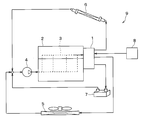
- the valve device 1 of the present embodiment is used in a cooling water circuit of an engine mounted on a vehicle. As shown in FIG. 1, the valve device 1 is applied to the vehicle cooling system 9.
- the vehicle is equipped with an engine 2, a cooling system 9, a heater 6, a device 7, and the like as an internal combustion engine.
- the cooling system 9 includes a valve device 1, a water pump 4, a radiator 5, an ECU 8, and the like.
- the water pump 4 pumps the cooling water toward the water jacket 3 of the engine 2.
- the valve device 1 is provided, for example, at the outlet of the water jacket 3 of the engine 2 and adjusts the flow rate of the cooling water sent to the radiator 5, the heater 6, and the device 7.
- the radiator 5 is a heat exchanger that exchanges heat between the cooling water and air to lower the temperature of the cooling water.
- the heater 6 and the device 7 are provided between the valve device 1 and the water pump 4.
- the device 7 includes, for example, an oil cooler, an EGR cooler, and the like.
- the heater 6 heats the air inside the vehicle by exchanging heat between the cooling water and the air inside the vehicle.
- heat exchange is performed between the fluid (for example, oil, EGR gas, etc.) flowing through the device 7 and the cooling water.
- the ECU 8 can control the operation of the valve device 1 and control the flow rate of the cooling water sent to the radiator 5, the heater 6, and the device 7.
- the valve device 1 can adjust the flow rate of the cooling water as the fluid circulating in the cooling water circuit and switch the flow path.
- the cooling water for example, LLC (Long Life Coolant) containing ethylene glycol is used.
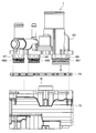
- the valve device 1 of the present embodiment includes a housing 10, an outlet pipe component 60, and a gasket 70 that seals between the valve body 30 and the outlet pipe component 60. ..
- a plurality of protrusions 65 to 67 are formed on the outlet pipe constituent member 60.
- the housing 10 and the outlet pipe component 60 are each made of resin, and the gasket 70 is made of an elastic member.
- the housing 10 and the outlet pipe component 60 form the outer shell of the valve device 1.
- the housing 10, the outlet pipe component 60, and the gasket 70 are fixed and integrated by tapping screws described later.
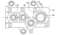
- the housing 10 has a housing body 11, a first bearing 18 for supporting the shaft 31, a plate 14, and the like, which form a part of the outer shell of the valve device 1.
- a storage space 13 in which the shaft 31, the valve body 30, and the like are housed is formed inside the housing body 11.
- the housing main body 11 includes a fluid inlet portion 24 for allowing the cooling water to flow into the accommodation space 13, and first to third fluid outlet portions 153 and 154 for allowing the cooling water to flow out from the accommodation space 13 to the outlet pipe constituent member 60. 155 is formed.
- the plate 14 is provided with a second bearing 19.
- the shaft 31 is rotatably supported inside the housing body 11 by its first bearing 18 and second bearing 19.
- the shaft 31 rotates about an axis by driving an electric motor (not shown) provided on the outside of the housing body 11.
- the valve body 30 is fixed to the shaft 31. Therefore, as the shaft 31 rotates, the valve body 30 rotates around the axis of the shaft 31 inside the housing body 11.
- the shaft of the shaft 31 and the rotation shaft Ax of the valve body 30 coincide with each other.
- the valve body 30 has a shaft fixing portion 300, a first cylinder portion 310, a second cylinder portion 320, a plurality of first connecting portions 330, and a plurality of second connecting portions 340.
- the shaft fixing portion 300 is fixed to the outer wall of the shaft 31.
- the first tubular portion 310 and the second tubular portion 320 are provided at positions separated radially outward from the shaft fixing portion 300.
- the first tubular portion 310 is provided on one side of the shaft 31 in the axial direction
- the second tubular portion 320 is provided on the other side of the shaft 31 in the axial direction.
- the first cylinder portion 310 the one on the right side of the paper surface in FIG. 3
- the second cylinder portion 320 is referred to as the second cylinder portion 320.
- a predetermined gap 200 is provided between the first cylinder portion 310 and the second cylinder portion 320.
- the predetermined gap 200 is provided at a position corresponding to the fluid inlet portion 24 of the housing main body 11.
- the predetermined gap 200 between the first cylinder portion 310 and the second cylinder portion 320 and the fluid inlet portion 24 of the housing body 11 are in directions perpendicular to the rotation axis Ax of the valve body 30. It is provided so that at least a part of it overlaps when viewed from the viewpoint.
- a spherical surface 311 is formed on the outer wall of the first tubular portion 310.
- a first valve outlet 373 from which the cooling water flows out is provided on a part of the spherical surface 311.
- the plurality of first connecting portions 330 extend radially between the end of the first tubular portion 310 on the side of the second tubular portion 320 and the shaft fixing portion 300, and the first tubular portion 310 and the shaft fixing portion 300 Are connected.
- a first valve inflow port 381 is formed between the plurality of first connecting portions 330.
- the first valve inflow port 381 is the first cylinder portion of the valve body 30 from the space inside the housing body 11 (specifically, a predetermined gap 200 between the first cylinder portion 310 and the second cylinder portion 320). It is an inflow port where cooling water flows into the space 331 inside the 310.
- two spherical surfaces 321 and 322 having different center points are formed on the outer wall of the second tubular portion 320.
- the second valve outlet 374 is provided on one spherical surface 321 and the third valve outlet 375 is provided on the other spherical surface 322. It is provided.
- the plurality of second connecting portions 340 extend radially between the end portion of the second tubular portion 320 on the side of the first tubular portion 310 and the shaft fixing portion 300, and the second tubular portion 320 and the shaft fixing portion 300 Are connected.
- a second valve inflow port 382 is formed between the plurality of second connecting portions 340.
- the second valve inflow port 382 is the second cylinder portion of the valve body 30 from the space inside the housing body 11 (specifically, a predetermined gap 200 between the first cylinder portion 310 and the second cylinder portion 320). It is an inflow port where cooling water flows into the space 332 inside the 320.
- both the first valve inflow port 381 and the second valve inflow port 382 of the valve body 30 are provided at the portions of the valve body 30 located in the rotation axis Ax direction.
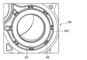
- the outlet pipe component 60 has first to third fluid inflow portions 651, 652, and 653 at positions corresponding to the first to third valve outlets 373, 374, and 375 in the housing main body 11.
- the outlet pipe component 60 further includes first to third fluid outlets 61, 62, 63 for discharging cooling water from the outlet pipe component 60, and first to third pipe connection portions 641, 642, 643. have.
- the first to third pipe connection portions 641, 642, and 643 each have a tubular shape. Pipes (not shown) through which cooling water flows are connected to the first to third pipe connecting portions 641, 642, and 643, respectively.
- the first fluid outlet 61 is formed in the first pipe connection portion 641.
- the second fluid outlet 62 is formed in the second pipe connecting portion 642, and the third fluid outlet 63 is formed in the third pipe connecting portion 643.
- first to third fluid inflow portions 651, 652, 653 are provided with first to third sleeves 43, 44, 45, first to third seat members 53, 54, 55, etc., respectively. ..
- the first to third sleeves 43, 44, and 45 are slidably supported by the inner walls of the first to third fluid inflow portions 651, 652, and 653 included in the outlet pipe component 60.
- the first to third sleeves 43, 44, and 45 form a flow path through which cooling water flows out from the space inside the valve body 30 via the first to third valve outlets 373, 374, and 375.
- the first to third sleeves 43, 44, and 45 have first to third flange portions 461, 462, and 463 for supporting the seat members 53, 54, and 55 at the ends on the valve body 30 side, respectively. There is.
- the first to third flange portions 461, 462, and 463 extend radially outward from the first to third sleeves 43, 44, and 45 from one end on the housing body 11 side of the first to third sleeves 43, 44, and 45. It is formed like this.
- the first seat member 53 is provided between the flange portion 461 of the first sleeve 43 and the outer wall of the first cylinder portion 310 of the valve body 30.
- the second and third seat members 54 and 55 include the second and third flange portions 462 and 463 of the second and third sleeves 44 and 45, respectively, and the outer wall of the second cylinder portion 320 of the valve body 30. It is provided between.
- the first to third sheet members 53, 54, and 55 are each formed in an annular shape, and cooling water flows on the inner diameter side thereof.
- the first seat member 53 is in sliding contact with the outer wall of the first cylinder portion 310 of the valve body 30. Further, the second and third seat members 54 and 55 are in sliding contact with the outer wall of the second cylinder portion 320 of the valve body 30.
- First to third springs 481, 482, 483 are provided between the first to third flange portions 461, 462, 463 of the first to third sleeves 43, 44, 45 and the outlet pipe component 60, respectively. It is provided.
- the first to third springs 481, 482, 483 are compression coil springs, and the first to third sleeves 43, 44, 45 and the first to third seat members 53, 54, 55 are attached to the valve body 30 side. It is gaining momentum.
- first to third seat members 53, 54, 55 come into close contact with the outer wall of the tubular portion 35 of the valve body 30.
- the first to third seat members 53, 54, 55 are formed in the space formed between the inner wall of the housing body 11 and the outer wall of the valve body 30, and inside the first to third sleeves 43, 44, 45. It prevents the cooling water from leaking between the flow path and the flow path.
- the cooling water flows into the accommodation space 13 of the housing body 11 from the fluid inlet portion 24 of the housing body 11.
- the accommodation space 13 The cooling water of the water flows as follows. That is, the cooling water in the accommodation space 13 flows through the first valve inlet 381 and the second valve inlet 382 of the valve body 30 to the first to third valve outlets 373, 374, 375 of the valve body 30. ..
- the cooling water further passes through the first to third seat members 53, 54, 55 and the first to third sleeves 43, 44, 45, and then the first to third fluid outlets of the outlet pipe component 60. It flows out from 61, 62, 63.
- the cooling water is a valve. It stays in the accommodation space 13 without flowing into the first valve inflow port 381 and the second valve inflow port 382 of the body 30.
- valve devices 1 are provided at the ends of the outlet pipe constituent members 60 on the opposite sides of the first to third springs 481, 482, and 483 from the valve body 30 side, respectively. It has a first protrusion 65, eight second protrusions 66, and eight third protrusions 67.
- the first to third protrusions 65, 66, and 67 correspond to the spring end support portion.
- the valve device 1 supports the spring end portion of the outlet pipe component 60 at a portion radially outer of the end portion of the first to third springs 481, 482, 483 opposite to the valve body 30 side.
- the first to third protrusions 65, 66, and 67 are provided as an example of the portion.
- the eight first protrusions 65 support the end of the first spring 481 on the side opposite to the valve body 30 side from the radial outside of the first spring 481. Further, the eight second protrusions 66 support the end portion of the second spring 482 opposite to the valve body 30 side from the radial outside of the spring 482. Further, the eight third protrusions 67 support the end portion of the third spring 483 on the side opposite to the valve body 30 side from the radial outside of the third spring 483.
- the first to third protrusions 65, 66, and 67 are opposite to the valve body 30 side of the first to third springs 481, 482, and 483 in the outlet pipe component 60, respectively.
- the first to third springs 481, 482, and 483 project radially outward from the end of the spring.
- the first protrusion 65 projects outward in the radial direction of the first spring 481 from the end of the outlet pipe component 60 on the side opposite to the valve body 30 side of the first spring 481. ..
- the first protrusion 65 is parallel to the axis CL of the first fluid inflow portion 651 from a portion of the outlet pipe component 60 that is radially outer from the end portion of the first spring 481 opposite to the valve body 30 side. It extends to. Then, the first protrusion 65 supports the end portion of the first spring 481 on the side opposite to the valve body 30 side from the radial outside of the first spring 481.
- the axis CL of the first fluid inflow portion 651 coincides with the axis CL of the first sleeve 43.
- the configurations of the second and third protrusions 66 and 67 are substantially the same as the configurations of the first protrusion 65.
- first to third protrusions 65, 66, and 67 are inserted into the first to third fluid outlets 153, 154, and 155 formed in the housing body 11, respectively.
- the first to third protrusions 65, 66, and 67 are formed at positions where they come into contact with the inner peripheral surfaces of the first to third fluid outlets 153, 154, and 155 formed in the housing body 11.
- the first to third protrusions 65, 66, and 67 also function as guides when assembling the housing body 11 and the outlet pipe component 60.
- the housing 10 and the outlet pipe component 60 are fixed by a tapping screw 80 as an example of a screw.
- the outlet pipe component 60 is formed with a screw fixing portion 68 in which a through hole 681 for inserting the tapping screw 80 is formed.
- the housing 10 includes a housing main body 11 having a flow path through which a fluid flows, a screw fastening portion 110 to which the tapping screw 80 is fastened, and a connecting portion 120 connecting the housing main body 11 and the screw fastening portion 110. have.
- the operator inserts the tapping screw 80 into the through hole 681 formed in the screw fixing portion 68, and then tightens and fixes the tapping screw 80 to the screw fastening portion 110 of the housing 10.
- the operator tightens and fixes the tapping screw 80 by cutting into the screw fastening portion 110 of the housing 10.
- the housing 10 and the outlet pipe component 60 are integrated.
- a hole 130 is formed in a connecting portion 120 that connects the housing body 11 and the screw fastening portion 110.
- the hole 130 is formed between the screw fastening portion 110 and the housing body 11.
- the hole 130 is formed so as to penetrate the connecting portion 120 in the vertical direction.
- the hole 130 is formed in the connecting portion 120 that connects the housing body 11 and the screw fastening portion 110. Therefore, when the tapping screw 80 is tightened and fixed to the screw fastening portion 110 of the housing 10, even if the screw fastening portion 110 is cracked and cracked, the crack grows along the connecting portion 120, and the hole 130 It does not stop and spread to the housing body 11 side. Therefore, leakage of the cooling water inside the housing 10 is prevented.
- the valve device 1 of the present embodiment includes a case member composed of the housing 10 and the outlet pipe component 60.
- the case members include a fluid inlet portion 24 into which a fluid flows, first to third fluid inflow portions 651, 652, 653 in which a fluid flowing in from the fluid inlet portion 24 flows, and first to third fluid inflow portions 651, 652.
- the first to third fluid outlets 61, 62, 63 which allow the fluid to flow out through 653.
- the valve device 1 has first to third valve outlets 373, 374, 375 through which the fluid flowing in from the fluid inlet portion flows, and includes a valve body 30 rotatably provided inside the case member. There is.
- valve device 1 is slidably supported by the inner wall of the fluid inflow portion, and guides the fluid flowing out from the first to third valve outlets 373, 374, and 375 to the fluid outlet side of the case member.
- the tubular first to third sleeves 43, 44, and 45 to be formed are provided.
- the valve device 1 is arranged so as to surround the outer peripheral surfaces of the first to third sleeves 43, 44, 45, and the first to third sleeves 43, 44, 45 are urged toward the valve body 30 side.
- the third springs 481, 482, 483 are provided.
- the valve device 1 is provided with a spring end support portion at an end portion of the case member on the side opposite to the valve body 30 side of the first to third springs 481, 482, 483.
- the spring end support portion has the end portion of the first to third springs 481, 482, 483 opposite to the valve body 30 side in the axial direction, which is radially outside of the first to third springs 481, 482, 483. Support from.
- the first to third springs 481, 482, 483 are formed on the end opposite to the valve body 30 side of the first to third springs 481, 482, 483 in the case member.
- the ends of the springs 481, 482, and 483 on the side opposite to the valve body 30 side in the axial direction are supported. Therefore, the first to third springs 481, 482, 483 and the first to third sleeves 43, 44, 45 do not come into contact with each other, and the misalignment of the first to third springs 481, 482, 483 is prevented. Therefore, wear of the first to third springs 481, 482, 483 and the first to third sleeves 43, 44, 45 can be suppressed.
- the spring end support portions are a plurality of spring end support portions that project toward the valve body 30 side from the end portions of the case member that are opposite to the valve body 30 side in the axial direction of the first to third springs 481, 482, 483. It has first to third protrusions 65, 66, 67. In this way, the spring end support portion can be formed by the plurality of first to third protrusions 65, 66, 67.
- the case member includes a housing 10 having a fluid inlet portion 24, and an outlet pipe component 60 having first to third fluid inflow portions 651, 652, 653 and first to third fluid outlets 61, 62, 63. And have.
- the housing 10 has first to third fluid outlets 153, 154, and 155 that introduce the fluid flowing in from the fluid inlet 24 into the first to third fluid inflows 651, 652, and 653.
- the plurality of first to third protrusions 65, 66, 67 also function as guides when assembling the housing body 11 and the outlet pipe constituent member 60 when assembling the housing 10 and the outlet pipe constituent member 60.
- the outlet pipe component 60 has a screw fixing portion 68 in which a through hole 681 for inserting the tapping screw 80 is formed.
- the housing 10 includes a housing main body 11 having a flow path through which cooling water flows, a screw fastening portion 110 to which the tapping screw 80 is fastened, and a connecting portion 120 connecting the housing main body 11 and the screw fastening portion 110. ,have.
- the housing main body 11 and the outlet pipe constituent member 60 are attached to each other. Can be assembled. A hole 130 is formed between the screw fastening portion 110 and the housing body 11.
- the tapping screw 80 is cracked on the housing main body 11 side when the tapping screw 80 is tightened and fixed to the screw fastening portion 110. Can be prevented from progressing.
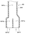
- the valve device 1 of the present embodiment includes an outlet pipe component 60 having a first pipe connecting portion 641. Further, the first pipe connecting portion 641 has a first inflow port 6411 into which the cooling water flows in, and a first flow path 641a in which the cooling water flowing in from the first inflow port 6411 flows. Further, it has a second inflow port 6412 into which the cooling water flows in, and a second flow path 641b in which the cooling water flowing in from the second inflow port 6412 flows. Further, the first pipe connecting portion 641 has a third flow path 641c through which the cooling water flowing through the first flow path 641a and the cooling water flowing through the second flow path 641b are combined to flow.
- the first flow path 641a and the second flow path 641b are formed so as to run side by side next to each other.
- first flow path 641a, the second flow path 641b, and the third flow path 641c of the first pipe connection portion 641 are not provided with right-angled portions that are perpendicular to the flow direction of the cooling water. That is, at the confluence portion where the cooling water flowing through the first flow path 641a and the cooling water flowing through the second flow path 641b merge, the first to third flow paths 641a, 641b, 641c of the first pipe connecting portion 641 are formed.
- the inner wall is formed so as to have an angle of 90 degrees or more with respect to the flow direction of the cooling water.
- the valve device 1 of the present embodiment includes an outlet pipe component 60 having a first pipe connecting portion 641 through which cooling water as a fluid flows.
- the first pipe connecting portion 641 has a first inflow port 6411 into which the cooling water flows in, and a first flow path 641a in which the cooling water flowing in from the first inflow port 6411 flows. Further, it has a second inflow port 6412 into which the cooling water flows in, and a second flow path 641b in which the cooling water flowing in from the second inflow port 6412 flows. Further, the first pipe connecting portion 641 has a third flow path 641c through which the cooling water flowing through the first flow path 641a and the cooling water flowing through the second flow path 641b are combined to flow.
- the first to third flow paths 641a, 641b, 641c of the first pipe connecting portion 641 are formed.
- the inner wall is formed so as to have an angle of 90 degrees or more with respect to the flow direction of the cooling water.
- the inner wall forming the first to third flow paths 641a, 641b, 641c of the first pipe connecting portion 641 is formed so as to be 90 degrees with respect to the flow direction of the cooling water.
- the water flow resistance can be reduced in comparison.
- FIGS. 9 to 10 A cross-sectional view of the valve device 1 of the present embodiment is shown in FIG. In FIG. 9, the valve device 1 is shown upside down. That is, the housing 10 is shown to be on the upper side in the vertical direction with respect to the outlet pipe constituent member 60.
- the outlet pipe component 60 of the present embodiment is provided with a relief valve 69 for suppressing the engine 2 from overheating when the electric motor that drives the shaft 31 fails.
- This relief valve 69 is arranged in the second flow path 641b of the first pipe connecting portion 641 shown in FIG. When the water temperature rises, the relief valve 69 mechanically opens to allow cooling water to flow from the third flow path 641c of the first pipe connecting portion 641 to the water jacket 3 of the engine 2.
- the outlet pipe component 60 of the present embodiment is formed with a joint surface 600 to be joined to the housing 10 and a recess 602 formed at a position recessed from the joint surface 600.
- the relief valve 69 has a flange portion 691 fixed to the outlet pipe component 60.
- the relief valve 69 is press-fitted and fixed in the recess 602 formed in the outlet pipe component 60.
- the outlet pipe component 60 is installed so that the joint surface 600 to be joined to the housing 10 of the outlet pipe component 60 faces upward in the vertical direction.
- the flange portion 691 of the relief valve 69 is press-fitted and fixed to the recess 602 formed in the outlet pipe component 60.
- the relief valve 69 is arranged so as to enter a recessed position from the joint surface 600 to be joined to the housing 10 of the outlet pipe component 60.
- the housing 10 is prepared, the housing 10 is arranged so as to cover the outlet pipe constituent member 60 from above, and the outlet pipe constituent member 60 is screwed to the housing 10.
- FIG. 1 A cross-sectional view of a conventional valve device is shown in FIG.
- the relief valve 69 is fixed to the joint surface 600 to be joined to the housing 10 of the outlet pipe component 60. Therefore, the stability of the relief valve 69 when the outlet pipe component 60 is assembled to the housing 10 is not good.
- the valve device 1 of the present embodiment includes a housing 10 and an outlet pipe component 60 having a first pipe connecting portion 641 through which cooling water as a fluid flows. Further, a relief valve 69 is provided which is arranged in the second flow path 641b of the first pipe connection portion 641 and mechanically opens and closes the second flow path 641b. Further, the outlet pipe component 60 is formed with a joint surface 600 to be joined to the housing 10 and a recess 602 formed at a position recessed from the joint surface 600. Further, the relief valve 69 has a flange portion 691 fixed to the outlet pipe constituent member 60. The relief valve 69 has a flange portion 691 fixed to a recess 602 formed in the outlet pipe constituent member 60.
- the relief valve 69 since the flange portion 691 is fixed to the recess 602 formed in the outlet pipe constituent member 60, the relief valve 69 when assembling the outlet pipe constituent member 60 to the housing 10 The stability of the can be improved.
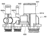
- FIG. 11 shows a front view of the outlet pipe component 60 of the valve device according to the fourth embodiment.
- the positions of the first to third stoppers 641d, 642d, 643d formed in the first to third pipe connecting portions 641, 642, 643 are the same. That is, the lengths from the joint surface 600 of the outlet pipe component 60 to the housing 10 to the first to third stoppers 641d, 642d, and 643d are the same.
- a hose (not shown) is connected to the first to third pipe connection portions 641, 642, 643.
- the first to third stoppers 641d, 642d, 643d come into contact with the hoses attached to the first to third pipe connecting portions 641, 642, 643.
- the valve device 1 of the present embodiment includes a housing 10 and an outlet pipe component 60 in which the first to third pipe connecting portions 641, 642, 643 are formed. Further, the outlet pipe constituent member 60 is formed with first to third stoppers 641d, 642d, 643d that come into contact with the tip of the hose attached to the outlet pipe constituent member 60. The lengths of the outlet pipe component 60 from the joint surface 600 with the housing 10 to the first to third stoppers 641d, 642d, and 643d are the same.
- the valve device according to the fifth embodiment will be described with reference to FIGS. 12 to 13.
- the valve device 1 of the present embodiment is different from the valve device 1 of the first embodiment in that it further has ribs 121.
- the rib 121 is formed so as to expand in a direction orthogonal to the axial direction of the screw hole of the screw fastening portion 110.
- a hole 130 can be formed in the connecting portion 120 that connects the housing body 11 and the screw fastening portion 110.
- the spring end support portion is formed by eight protrusions 65, but the number of protrusions 65 is not limited to eight.
- a ring-shaped spring end support portion may be formed at an end portion of the outlet pipe component 60 on the side opposite to the valve body 30 side of the first to third springs 481, 482, 483. Then, by the ring-shaped spring end support portion, the end portions of the first to third springs 481, 482, 483 opposite to the valve body 30 side are arranged in the radial direction of the first to third springs 481, 482, 483. It may be supported from the outside.
- the outlet pipe component 60 of the first embodiment has a plurality of first to third protrusions 65, 66, 67 as spring end support portions.
- a plurality of first to third protrusions 65, 66, 67 as spring end support portions may be provided separately from the outlet pipe constituent member 60.
- the present disclosure is not limited to the above-described embodiment, and can be changed as appropriate. Further, the above-described embodiments are not unrelated to each other, and can be appropriately combined unless the combination is clearly impossible. Further, in each of the above embodiments, it goes without saying that the elements constituting the embodiment are not necessarily essential except when it is clearly stated that they are essential and when they are clearly considered to be essential in principle. No. Further, in each of the above embodiments, when numerical values such as the number, numerical values, amounts, and ranges of the constituent elements of the embodiment are mentioned, when it is clearly stated that they are particularly essential, and in principle, the number is clearly limited to a specific number. It is not limited to the specific number except when it is done.
- the housing 10 and the outlet pipe component 60 correspond to the case member, and the protrusions 65 to 67 correspond to the spring end support portion.
Landscapes
- Engineering & Computer Science (AREA)
- General Engineering & Computer Science (AREA)
- Mechanical Engineering (AREA)
- Valve Housings (AREA)
- Multiple-Way Valves (AREA)
- Sliding Valves (AREA)
- Taps Or Cocks (AREA)
Abstract
バルブ装置は、ケース部材(10、60)、バルブ体(30)、スリーブ(43、44、45)、スプリング(481、482、483)およびスプリング端部支持部(65、66、67)を備える。スリーブはケース部材の有する流体流入部(651、652、653)の内壁により摺動可能に支持され、バルブ体の有するバルブ流出口(373、374、375)から流出した流体をケース部材の有する流体流出口(61、62、63)側に導く流路を形成する。スプリングはスリーブの外周面を囲むように配置され、スリーブをバルブ体側に付勢する。スプリング端部支持部は、ケース部材におけるスプリングのバルブ体側とは反対側の端部に形成され、スプリングの軸方向のバルブ体側とは反対側の端部をスプリングの径方向外側から支持する。
Description
本出願は、2019年11月7日に出願された日本特許出願番号2019-202524号に基づくもので、ここにその記載内容が参照により組み入れられる。
本開示は、流体の流量調整および流路切替の少なくとも一方を行うバルブ装置に関するものである。
従来、特許文献1に記載されたバルブ装置がある。この装置は、冷却水が導入されるインレットおよび冷却水が排出されるアウトレットが設けられたハウジングと、インレットから供給される冷却水が流れるバルブ開口を有し回転可能に支持されたバルブと、を備えている。この装置は、バルブ開口を通過した冷却水が流れるシート開口を有するバルブシートと、シート開口を通過した冷却水をアウトレットへ導く円筒状のスリーブと、スリーブの周囲に装着されてバルブシートをバルブの表面に押し付けるスプリングと、を備えている。
上記特許文献1に記載されたものは、単に、スプリングがスリーブの周囲を囲むように配置されておりスプリングの軸ずれが生じやすい。このため、外部からの振動等によってスプリングのスリーブの外周面への当たりが生じ、スプリングとスリーブの摩耗が進みやすい。このようにスプリングとスリーブの摩耗が進むと、スプリングがバルブシートをバルブの表面に押し付けるスプリング力が低下し冷却水の漏れが大きくなってしまうといった懸念がある。
本開示は、スプリングとスリーブとの摩耗を抑制することを目的とする。
本開示は、スプリングとスリーブとの摩耗を抑制することを目的とする。
本開示の1つの観点によれば、流体の流量調整および流路切替の少なくとも一方を行うバルブ装置は、流体が流入する流体入口部と、流体入口部から流入した流体が流れる流体流入部と、流体流入部を通った流体を流出させる流体流出口と、を有するケース部材と、流体入口部から流入した流体が流れるバルブ流出口を有し、ケース部材の内側に回転可能に設けられたバルブ体と、流体流入部の内壁により摺動可能に支持され、バルブ流出口から流出した流体をケース部材の流体流出口側に導く流路を形成する筒状のスリーブと、スリーブの外周面を囲むように配置され、スリーブをバルブ体側に付勢するスプリングと、ケース部材におけるスプリングのバルブ体側とは反対側の端部に形成され、スプリングの軸方向のバルブ体側とは反対側の端部をスプリングの径方向外側から支持するスプリング端部支持部と、を備えている。
このような構成によれば、ケース部材におけるスプリングのバルブ体側とは反対側の端部に形成されたスプリング端部支持部により、スプリングの軸方向のバルブ体側とは反対側の端部が支持される。したがって、スプリングの軸ずれが防止され、スプリングとスリーブとの摩耗を抑制することができる。
なお、各構成要素等に付された括弧付きの参照符号は、その構成要素等と後述する実施形態に記載の具体的な構成要素等との対応関係の一例を示すものである。
以下、本開示の実施形態について図面を参照しつつ説明する。なお、以下の各実施形態相互において、互いに同一もしくは均等である部分には、同一符号を付し、その説明を省略する。
(第1実施形態)
第1実施形態に係るバルブ装置について図面を参照しつつ説明する。本実施形態のバルブ装置1は、車両に搭載されるエンジンの冷却水回路に用いられるものである。図1に示すように、バルブ装置1は、車両の冷却システム9に適用される。車両には、内燃機関としてのエンジン2、冷却システム9、ヒータ6、デバイス7等が搭載されている。
第1実施形態に係るバルブ装置について図面を参照しつつ説明する。本実施形態のバルブ装置1は、車両に搭載されるエンジンの冷却水回路に用いられるものである。図1に示すように、バルブ装置1は、車両の冷却システム9に適用される。車両には、内燃機関としてのエンジン2、冷却システム9、ヒータ6、デバイス7等が搭載されている。
冷却システム9は、バルブ装置1、ウォーターポンプ4、ラジエータ5、ECU8等を備えている。ウォーターポンプ4は、冷却水をエンジン2のウォータージャケット3に向けて圧送する。バルブ装置1は、例えばエンジン2のウォータージャケット3の出口に設けられ、ラジエータ5、ヒータ6、デバイス7へ送る冷却水の流量を調整する。
ラジエータ5は、熱交換器であり、冷却水と空気との間で熱交換を行い冷却水の温度を下げる。ヒータ6およびデバイス7は、バルブ装置1とウォーターポンプ4との間に設けられている。ここで、デバイス7は、例えばオイルクーラ、EGRクーラ等を含む。
ヒータ6は、冷却水と車両の室内の空気との熱交換により車両の室内の空気を加熱する。デバイス7に冷却水を流すと、デバイス7を流れる流体(例えばオイル、EGRガス等)と冷却水との間で熱交換が行われる。ECU8は、バルブ装置1の作動を制御し、ラジエータ5、ヒータ6、デバイス7へ送る冷却水の流量を制御可能である。
バルブ装置1は、冷却水回路を循環する流体としての冷却水の流量の調整および流路の切替を行うことが可能である。なお、冷却水としては、例えば、エチレングリコールを含むLLC(Long Life Coolant)などが用いられる。
図2に示すように、本実施形態のバルブ装置1は、ハウジング10と、出口パイプ構成部材60と、バルブ体30と出口パイプ構成部材60との間をシールするガスケット70と、を備えている。なお、出口パイプ構成部材60には、複数の突起65~67が形成されている。ハウジング10および出口パイプ構成部材60は、それぞれ樹脂により構成され、ガスケット70は弾性部材により構成されている。ハウジング10および出口パイプ構成部材60は、バルブ装置1の外殻を構成している。ハウジング10、出口パイプ構成部材60およびガスケット70は、後述するタッピングネジにより固定され一体化される。
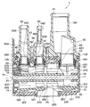
図3に示すように、ハウジング10は、バルブ装置1の外殻の一部を構成するハウジング本体11、シャフト31を支持する第1軸受18およびプレート14等を有している。ハウジング本体11の内側には、シャフト31、バルブ体30等が収容される収容空間13が形成されている。また、ハウジング本体11には、冷却水を収容空間13に流入させる流体入口部24と、冷却水を収容空間13から出口パイプ構成部材60へ流出させる第1~第3流体出口部153、154、155が形成されている。また、プレート14には、第2軸受19が設けられている。
シャフト31は、その第1軸受18と第2軸受19によりハウジング本体11の内側に回転可能に支持されている。なお、シャフト31は、ハウジング本体11の外側に設けられた図示しない電動モータの駆動により軸周りに回転する。
バルブ体30はシャフト31に固定されている。そのため、シャフト31の回転に伴って、バルブ体30は、ハウジング本体11の内側でシャフト31の軸周りに回転動作する。なお、シャフト31の軸とバルブ体30の回転軸Axとは一致している。
バルブ体30は、シャフト固定部300、第1筒部310、第2筒部320、複数の第1連結部330、および複数の第2連結部340を有している。
シャフト固定部300は、シャフト31の外壁に固定されている。第1筒部310と第2筒部320は、シャフト固定部300から径方向外側に離れた位置に設けられている。第1筒部310はシャフト31の軸方向の一方の側に設けられ、第2筒部320はシャフト31の軸方向の他方の側に設けられている。以下の説明では、2つの筒部のうち、図3の紙面右側のものを第1筒部310と呼び、紙面左側のものを第2筒部320と呼ぶこととする。
第1筒部310と第2筒部320との間には、所定の空隙200が設けられている。その所定の空隙200は、ハウジング本体11の流体入口部24に対応する位置に設けられている。具体的には、第1筒部310と第2筒部320との間の所定の空隙200と、ハウジング本体11の流体入口部24とは、バルブ体30の回転軸Axに対して垂直な方向から視て少なくとも一部が重なるように設けられている。
第1筒部310の外壁には、球状面311が形成されている。その球状面311の一部に冷却水が流出する第1バルブ流出口373が設けられている。
複数の第1連結部330は、第1筒部310のうち第2筒部320側の端部とシャフト固定部300との間で放射状に延びて、第1筒部310とシャフト固定部300とを連結している。その複数の第1連結部330同士の間に第1バルブ流入口381が形成されている。
第1バルブ流入口381は、ハウジング本体11の内側の空間(具体的には、第1筒部310と第2筒部320との間の所定の空隙200)からバルブ体30の第1筒部310の内側の空間331に冷却水が流入する流入口である。
一方、第2筒部320の外壁には、中心点の異なる2つの球状面321、322が形成されている。第2筒部320の外壁に形成された2つの球状面321、322のうち、一方の球状面321に第2バルブ流出口374が設けられ、他方の球状面322に第3バルブ流出口375が設けられている。
複数の第2連結部340は、第2筒部320のうち第1筒部310側の端部とシャフト固定部300との間で放射状に延びて、第2筒部320とシャフト固定部300とを連結している。その複数の第2連結部340同士の間に第2バルブ流入口382が形成されている。
第2バルブ流入口382は、ハウジング本体11の内側の空間(具体的には、第1筒部310と第2筒部320との間の所定の空隙200)からバルブ体30の第2筒部320の内側の空間332に冷却水が流入する流入口である。このように、本実施形態では、バルブ体30の第1バルブ流入口381と第2バルブ流入口382はいずれも、バルブ体30のうち回転軸Ax方向に位置する部位に設けられている。
出口パイプ構成部材60は、ハウジング本体11における第1~第3バルブ流出口373、374、375に対応する位置にそれぞれ第1~第3流体流入部651、652、653を有している。
出口パイプ構成部材60は、さらに、冷却水を出口パイプ構成部材60から流出させる第1~第3流体流出口61、62、63と、第1~第3パイプ接続部641、642、643と、を有している。
第1~第3パイプ接続部641、642、643は、それぞれ筒状を成している。第1~第3パイプ接続部641、642、643には、それぞれ冷却水が流れる図示しないパイプが接続される。
第1流体流出口61は、第1パイプ接続部641に形成されている。第2流体流出口62は、第2パイプ接続部642に形成され、第3流体流出口63は、第3パイプ接続部643に形成されている。
また、第1~第3流体流入部651、652、653には、それぞれ、第1~第3スリーブ43、44、45、第1~第3シート部材53、54、55などが設けられている。第1~第3スリーブ43、44、45は、出口パイプ構成部材60が有する第1~第3流体流入部651、652、653の内壁により摺動可能に支持されている。
第1~第3スリーブ43、44、45は、バルブ体30の内側の空間から第1~第3バルブ流出口373、374、375を介して冷却水が流出する流路を形成している。第1~第3スリーブ43、44、45はそれぞれ、バルブ体30側の端部にシート部材53、54、55を支持するための第1~第3フランジ部461、462、463を有している。第1~第3フランジ部461、462、463は、第1~第3スリーブ43、44、45のハウジング本体11側の一端から第1~第3スリーブ43、44、45の径方向外側に拡がるように形成されている。
第1シート部材53は、第1スリーブ43が有するフランジ部461と、バルブ体30の第1筒部310の外壁との間に設けられている。また、第2、第3シート部材54、55は、第2、第3スリーブ44、45がそれぞれ有する第2、第3フランジ部462、463と、バルブ体30の第2筒部320の外壁との間に設けられている。第1~第3シート部材53、54、55はそれぞれ環状に形成されており、その内径側を冷却水が流れる。
第1シート部材53は、バルブ体30の第1筒部310の外壁に摺接している。また、第2、第3シート部材54、55は、バルブ体30の第2筒部320の外壁に摺接している。第1~第3スリーブ43、44、45の第1~第3フランジ部461、462、463と出口パイプ構成部材60との間には、それぞれ、第1~第3スプリング481、482、483が設けられている。第1~第3スプリング481、482、483は、圧縮コイルスプリングであり、第1~第3スリーブ43、44、45と第1~第3シート部材53、54、55をバルブ体30側へ付勢している。これにより、第1~第3シート部材53、54、55は、バルブ体30の筒部35の外壁に密着する。この第1~第3シート部材53、54、55は、ハウジング本体11の内壁とバルブ体30の外壁との間に形成される空間と、第1~第3スリーブ43、44、45の内側の流路と間で、冷却水が漏れることを防いでいる。
冷却水は、ハウジング本体11の流体入口部24からハウジング本体11の収容空間13に流入する。
ここで、バルブ体30の第1~第3バルブ流出口373、374、375が出口パイプ構成部材60の第1~第3流体流入部651、652、653と連通している場合、収容空間13の冷却水は、以下のように流れる。すなわち、収容空間13の冷却水は、バルブ体30の第1バルブ流入口381、第2バルブ流入口382を通ってバルブ体30の第1~第3バルブ流出口373、374、375へと流れる。
この冷却水は、さらに、第1~第3シート部材53、54、55および第1~第3スリーブ43、44、45を通った後、出口パイプ構成部材60の第1~第3流体流出口61、62、63から流出する。
また、バルブ体30の第1~第3バルブ流出口373、374、375が出口パイプ構成部材60の第1~第3流体流入部651、652、653と連通していない場合、冷却水はバルブ体30の第1バルブ流入口381、第2バルブ流入口382に流入されずに収容空間13に留まる。
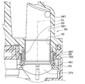
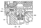
図3、図5に示すように、本バルブ装置1は、出口パイプ構成部材60における第1~第3スプリング481、482、483のバルブ体30側とは反対側の端部に、それぞれ8つの第1突起65、8つの第2突起66、8つの第3突起67を有している。第1~第3突起65、66、67は、スプリング端部支持部に相当する。言い換えれば、本バルブ装置1は、出口パイプ構成部材60のうち第1~第3スプリング481、482、483のバルブ体30側とは反対側の端部より径方向外側の部位にスプリング端部支持部の一例としての第1~第3突起65、66、67を備えている。
8つの第1突起65は、第1スプリング481のバルブ体30側とは反対側の端部を第1スプリング481の径方向外側から支持する。また、8つの第2突起66は、第2スプリング482のバルブ体30側とは反対側の端部をスプリング482の径方向外側から支持する。また、8つの第3突起67は、第3スプリング483のバルブ体30側とは反対側の端部を第3スプリング483の径方向外側から支持する。
図2、図3に示すように、第1~第3突起65、66、67は、それぞれ出口パイプ構成部材60における第1~第3スプリング481、482、483のバルブ体30側とは反対側の端部から第1~第3スプリング481、482、483の径方向外側に向かって突出している。
図4に示すように、第1突起65は、出口パイプ構成部材60における第1スプリング481のバルブ体30側とは反対側の端部から第1スプリング481の径方向外側に向かって突出している。言い換えれば、第1突起65は、出口パイプ構成部材60のうち第1スプリング481のバルブ体30側とは反対側の端部より径方向外側の部位から第1流体流入部651の軸線CLと平行に延出している。そして、第1突起65は、第1スプリング481のバルブ体30側とは反対側の端部を第1スプリング481の径方向外側から支持する。なお、第1流体流入部651の軸線CLは、第1スリーブ43の軸芯と一致している。第2、第3突起66、67の構成は第1突起65の構成と実質的に同一である。
これにより、外部からの振動等がバルブ装置1に伝搬しても、第1~第3スプリング481、482、483の軸ずれが抑制される。したがって、第1~第3スプリング481、482、483と第1~第3スリーブ43、44、45の摩耗が抑制され、冷却水の漏れが抑制される。
また第1~第3突起65、66、67は、それぞれハウジング本体11に形成された第1~第3流体出口部153、154、155に挿入される。第1~第3突起65、66、67は、ハウジング本体11に形成された第1~第3流体出口部153、154、155の内周面と接触する位置に形成されている。そして、第1~第3突起65、66、67は、ハウジング本体11と出口パイプ構成部材60とを組み付ける際のガイドとしての機能を兼ねる。
図7に示すように、本実施形態のバルブ装置1は、ハウジング10と出口パイプ構成部材60とがネジの一例としてのタッピングネジ80によって固定されている。
出口パイプ構成部材60には、タッピングネジ80を挿通するための貫通孔681が形成されたネジ固定部68が形成されている。
また、ハウジング10は、流体が流れる流路を有するハウジング本体11と、タッピングネジ80が締結されるネジ締結部110と、ハウジング本体11とネジ締結部110との間を連結する連結部120と、を有している。
作業者は、ネジ固定部68に形成された貫通孔681にタッピングネジ80を挿通させた後、タッピングネジ80をハウジング10のネジ締結部110に締め付け固定する。なお、作業者はタッピングネジ80をハウジング10のネジ締結部110に切り込むようにして締め付け固定する。これにより、ハウジング10と出口パイプ構成部材60とが一体化している。
本実施形態のハウジング10は、ハウジング本体11とネジ締結部110との間を連結する連結部120に穴部130が形成されている。穴部130は、ネジ締結部110とハウジング本体11との間に形成されている。穴部130は、連結部120を上下方向に貫通するように形成されている。
この穴部130が形成されていない場合、タッピングネジ80をハウジング10のネジ締結部110に締め付け固定する際に、タッピングネジ80を切り込む力が強いと、ネジ締結部110に亀裂が入って割れてしまう。そして、このような割れが拡がるとハウジング10の内部の冷却水の漏れが生じてしまう。
しかし、本実施形態のバルブ装置1は、ハウジング本体11とネジ締結部110との間を連結する連結部120に穴部130が形成されている。このため、タッピングネジ80をハウジング10のネジ締結部110に締め付け固定する際に、ネジ締結部110に亀裂が入って割れが生じても連結部120に沿って亀裂が進展し、穴部130で止まり、ハウジング本体11側に拡がることはない。したがって、ハウジング10の内部の冷却水の漏れが防止される。
以上、説明したように、本実施形態のバルブ装置1は、ハウジング10と出口パイプ構成部材60によって構成されるケース部材を備えている。ケース部材は、流体が流入する流体入口部24と、流体入口部24から流入した流体が流れる第1~第3流体流入部651、652、653と、第1~第3流体流入部651、652、653を通った流体を流出させる第1~第3流体流出口61、62、63と、を有している。また、バルブ装置1は、流体入口部から流入した流体が流れる第1~第3バルブ流出口373、374、375を有し、ケース部材の内側に回転可能に設けられたバルブ体30を備えている。また、バルブ装置1は、流体流入部の内壁により摺動可能に支持され、第1~第3バルブ流出口373、374、375から流出した流体をケース部材の流体流出口側に導く流路を形成する筒状の第1~第3スリーブ43、44、45を備えている。また、バルブ装置1は、第1~第3スリーブ43、44、45の外周面を囲むように配置され、第1~第3スリーブ43、44、45をバルブ体30側に付勢する第1~第3スプリング481、482、483を備えている。また、バルブ装置1は、ケース部材における第1~第3スプリング481、482、483のバルブ体30側とは反対側の端部にスプリング端部支持部を備えている。このスプリング端部支持部は、第1~第3スプリング481、482、483の軸方向のバルブ体30側とは反対側の端部を第1~第3スプリング481、482、483の径方向外側から支持する。
このような構成によれば、ケース部材における第1~第3スプリング481、482、483のバルブ体30側とは反対側の端部に形成されたスプリング端部支持部により、第1~第3スプリング481、482、483の軸方向のバルブ体30側とは反対側の端部が支持される。したがって、第1~第3スプリング481、482、483と第1~第3スリーブ43、44、45が接触することなく第1~第3スプリング481、482、483の軸ずれが防止される。したがって、第1~第3スプリング481、482、483と第1~第3スリーブ43、44、45との摩耗を抑制することができる。
また、スプリング端部支持部は、ケース部材における第1~第3スプリング481、482、483の軸方向のバルブ体30側とは反対側の端部からバルブ体30側に向かって突出する複数の第1~第3突起65、66、67を有している。このように、複数の第1~第3突起65、66、67によりスプリング端部支持部を構成することができる。
また、ケース部材は、流体入口部24を有するハウジング10と、第1~第3流体流入部651、652、653および第1~第3流体流出口61、62、63を有する出口パイプ構成部材60と、を有している。
また、ハウジング10は、流体入口部24から流入した流体を第1~第3流体流入部651、652、653に導入する第1~第3流体出口部153、154、155を有している。
また、複数の第1~第3突起65、66、67は、ハウジング10と出口パイプ構成部材60を組み付ける際に、ハウジング本体11と出口パイプ構成部材60とを組み付ける際のガイドとしても機能する。
したがって、スプリング端部支持部としての第1~第3突起65、66、67とは別にハウジング本体11と出口パイプ構成部材60とを組み付ける際のガイドを設ける場合と比較して小型化が可能である。
また、出口パイプ構成部材60は、タッピングネジ80を挿通するための貫通孔681が形成されたネジ固定部68を有している。
また、ハウジング10は、冷却水が流れる流路を有するハウジング本体11と、タッピングネジ80が締結されるネジ締結部110と、ハウジング本体11とネジ締結部110との間を連結する連結部120と、を有している。
ネジ固定部68に形成された貫通孔681に挿通されたタッピングネジ80をハウジング10に形成されたネジ締結部110に締め付け固定されていることにより、ハウジング本体11と出口パイプ構成部材60とが互いに組み付けられる。そして、ネジ締結部110とハウジング本体11との間に穴部130が形成されている。
このような構成によれば、ネジ締結部110とハウジング本体11との間に穴部130が形成されているので、タッピングネジ80をネジ締結部110に締め付け固定する際にハウジング本体11側に割れが進展するのを防止することができる。
(第2実施形態)
第2実施形態に係るバルブ装置について図8を用いて説明する。本実施形態のバルブ装置1は、第1パイプ接続部641を有する出口パイプ構成部材60を備えている。また、第1パイプ接続部641は、冷却水が流入する第1流入口6411と、第1流入口6411から流入した冷却水が流れる第1流路641aと、を有している。さらに、冷却水が流入する第2流入口6412と、第2流入口6412から流入した冷却水が流れる第2流路641bを有している。また、第1パイプ接続部641は、第1流路641aを流れる冷却水と第2流路641bを流れる冷却水が合流した冷却水が流れる第3流路641cを有している。
第2実施形態に係るバルブ装置について図8を用いて説明する。本実施形態のバルブ装置1は、第1パイプ接続部641を有する出口パイプ構成部材60を備えている。また、第1パイプ接続部641は、冷却水が流入する第1流入口6411と、第1流入口6411から流入した冷却水が流れる第1流路641aと、を有している。さらに、冷却水が流入する第2流入口6412と、第2流入口6412から流入した冷却水が流れる第2流路641bを有している。また、第1パイプ接続部641は、第1流路641aを流れる冷却水と第2流路641bを流れる冷却水が合流した冷却水が流れる第3流路641cを有している。
そして、第1流路641aを流れる冷却水と第2流路641bを流れる冷却水が途中で合流した後、第3流路641cを通って図示しない流体流出口から流出するようになっている。なお、第1流路641aと第2流路641bは、隣り合って並走するように形成されている。
また、第1パイプ接続部641の第1流路641a、第2流路641b、第3流路641c内には冷却水の流れ方向に対して直角となる直角部が設けられていない。すなわち、第1流路641aを流れる冷却水と第2流路641bを流れる冷却水が合流する合流部において、第1パイプ接続部641の第1~第3流路641a、641b、641cを形成する内壁は、冷却水の流れ方向に対して90度以上の角度となるよう形成されている。
これにより、第1パイプ接続部641の第1~第3流路641a、641b、641cを形成する内壁を、冷却水の流れ方向に対して90度となるよう形成する場合と比較して通水抵抗を小さくすることができる。また、出口パイプ構成部材60の成形時における所謂無理抜きがしやすくなるため出口パイプ構成部材60の加工コストを低減することが可能である。
以上、説明したように、本実施形態のバルブ装置1は、流体としての冷却水が流れる第1パイプ接続部641を有する出口パイプ構成部材60を備えている。第1パイプ接続部641は、冷却水が流入する第1流入口6411と、第1流入口6411から流入した冷却水が流れる第1流路641aを有している。また、冷却水が流入する第2流入口6412と、第2流入口6412から流入した冷却水が流れる第2流路641bを有している。また、第1パイプ接続部641は、第1流路641aを流れる冷却水と第2流路641bを流れる冷却水が合流した冷却水が流れる第3流路641cを有している。
そして、第1流路641aを流れる冷却水と第2流路641bを流れる冷却水が途中で合流した後、第3流路641cを通って流体流出口から流出するようになっている。また、第1流路641aを流れる冷却水と第2流路641bを流れる冷却水が合流する合流部において、第1パイプ接続部641の第1~第3流路641a、641b、641cを形成する内壁は、冷却水の流れ方向に対して90度以上の角度となるよう形成されている。
このような構成によれば、第1パイプ接続部641の第1~第3流路641a、641b、641cを形成する内壁を、冷却水の流れ方向に対して90度となるよう形成する場合と比較して通水抵抗を小さくすることができる。
(第3実施形態)
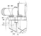
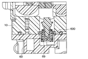
第3実施形態に係るバルブ装置について図9~図10を用いて説明する。本実施形態のバルブ装置1の断面図を図9に示す。なお、図9では、バルブ装置1を上下反転させて示してある。すなわち、ハウジング10が出口パイプ構成部材60に対して上下方向上側となるよう示してある。
第3実施形態に係るバルブ装置について図9~図10を用いて説明する。本実施形態のバルブ装置1の断面図を図9に示す。なお、図9では、バルブ装置1を上下反転させて示してある。すなわち、ハウジング10が出口パイプ構成部材60に対して上下方向上側となるよう示してある。
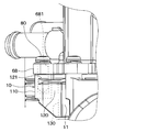
本実施形態の出口パイプ構成部材60には、シャフト31を駆動する電動モータが故障した際にエンジン2がオーバーヒートするのを抑制するためのリリーフ弁69が設けられている。
このリリーフ弁69は、図8に示した第1パイプ接続部641の第2流路641bに配置される。このリリーフ弁69は、水温が高くなるとメカニカル的に開弁して冷却水を第1パイプ接続部641の第3流路641cからエンジン2のウォータージャケット3に流す。
本実施形態の出口パイプ構成部材60には、ハウジング10と接合する接合面600と、この接合面600より凹んだ位置に形成された凹部602と、が形成されている。
一方、リリーフ弁69は、出口パイプ構成部材60に固定されるフランジ部691を有している。リリーフ弁69は、出口パイプ構成部材60に形成された凹部602に圧入固定される。
次に、ハウジング10への出口パイプ構成部材60の組付けについて説明する。
まず、出口パイプ構成部材60のハウジング10と接合する接合面600が上下方向上側を向くように出口パイプ構成部材60を設置する。
次に、リリーフ弁69のフランジ部691を、出口パイプ構成部材60に形成された凹部602に圧入固定する。これにより、リリーフ弁69は、出口パイプ構成部材60のハウジング10と接合する接合面600から凹んだ位置に入り込むように配置される。
次に、ハウジング10を用意するとともに、ハウジング10を出口パイプ構成部材60の上側から被せるように配置して出口パイプ構成部材60をハウジング10にネジ固定する。
従来のバルブ装置の断面図を図10に示す。従来のバルブ装置は、出口パイプ構成部材60のハウジング10と接合する接合面600にリリーフ弁69が固定されている。このため、出口パイプ構成部材60をハウジング10に組み付ける際のリリーフ弁69の安定性がよくない。
以上、説明したように、本実施形態のバルブ装置1は、ハウジング10と、流体としての冷却水が流れる第1パイプ接続部641を有する出口パイプ構成部材60を備えている。また、第1パイプ接続部641の第2流路641bに配置され、その第2流路641bを機械的に開閉するリリーフ弁69を備えている。また、出口パイプ構成部材60には、ハウジング10と接合する接合面600と、この接合面600より凹んだ位置に形成された凹部602と、が形成されている。また、リリーフ弁69は、出口パイプ構成部材60に固定されるフランジ部691を有している。そして、リリーフ弁69は、フランジ部691が、出口パイプ構成部材60に形成された凹部602に固定されている。
このような構成によれば、リリーフ弁69は、フランジ部691が、出口パイプ構成部材60に形成された凹部602に固定されるので、出口パイプ構成部材60をハウジング10に組み付ける際のリリーフ弁69の安定性を向上することができる。
(第4実施形態)
第4実施形態に係るバルブ装置の出口パイプ構成部材60の正面図を図11に示す。本実施形態のバルブ装置1は、第1~第3パイプ接続部641、642、643に形成された第1~第3ストッパー641d、642d、643dの位置が同じになっている。すなわち、出口パイプ構成部材60が有するハウジング10との接合面600から第1~第3ストッパー641d、642d、643dまでの長さが同じになっている。
第4実施形態に係るバルブ装置の出口パイプ構成部材60の正面図を図11に示す。本実施形態のバルブ装置1は、第1~第3パイプ接続部641、642、643に形成された第1~第3ストッパー641d、642d、643dの位置が同じになっている。すなわち、出口パイプ構成部材60が有するハウジング10との接合面600から第1~第3ストッパー641d、642d、643dまでの長さが同じになっている。
第1~第3パイプ接続部641、642、643には、図示しないホースが接続される。第1~第3ストッパー641d、642d、643dは、第1~第3パイプ接続部641、642、643に取り付けられるホースと当接する。
つまり、ホースを第1~第3パイプ接続部641、642、643に取り付ける際にホースの先端が第1~第3ストッパー641d、642d、643dに当接して、それ以上ホースが第1~第3パイプ接続部641、642、643の根元側に進まないようになっている。
以上、説明したように、本実施形態のバルブ装置1は、ハウジング10と、第1~第3パイプ接続部641、642、643が形成された出口パイプ構成部材60を備えている。また、出口パイプ構成部材60には、該出口パイプ構成部材60に取り付けられるホースの先端と当接する第1~第3ストッパー641d、642d、643dが形成されている。そして、出口パイプ構成部材60が有するハウジング10との接合面600から第1~第3ストッパー641d、642d、643dまでの長さが同じになっている。
このような構成によれば、ホースを第1~第3パイプ接続部641、642、643に組み付ける際の作業性を向上することができる。また、第1~第3パイプ接続部641、642、643に形成された第1~第3ストッパー641d、642d、643dの位置が異なる場合と比較して、成形性を向上することができる。
(第5実施形態)
第5実施形態に係るバルブ装置について図12~図13を用いて説明する。本実施形態のバルブ装置1は、上記第1実施形態のバルブ装置1と比較して、さらにリブ121を有している点が異なる。リブ121は、ネジ締結部110のネジ穴の軸方向に対して直交する方向に拡がるように形成されている。
第5実施形態に係るバルブ装置について図12~図13を用いて説明する。本実施形態のバルブ装置1は、上記第1実施形態のバルブ装置1と比較して、さらにリブ121を有している点が異なる。リブ121は、ネジ締結部110のネジ穴の軸方向に対して直交する方向に拡がるように形成されている。
このようなリブ121を有するバルブ装置1において、ハウジング本体11とネジ締結部110との間を連結する連結部120に穴部130を形成することもできる。
(他の実施形態)
(1)上記各実施形態では、8つの突起65によりスプリング端部支持部を構成したが、突起65の数は8つに限定されるものではない。また、出口パイプ構成部材60における第1~第3スプリング481、482、483のバルブ体30側とは反対側の端部にリング状のスプリング端部支持部を形成してもよい。そして、このリング状のスプリング端部支持部により第1~第3スプリング481、482、483のバルブ体30側とは反対側の端部を第1~第3スプリング481、482、483の径方向外側から支持するようにしてもよい。
(1)上記各実施形態では、8つの突起65によりスプリング端部支持部を構成したが、突起65の数は8つに限定されるものではない。また、出口パイプ構成部材60における第1~第3スプリング481、482、483のバルブ体30側とは反対側の端部にリング状のスプリング端部支持部を形成してもよい。そして、このリング状のスプリング端部支持部により第1~第3スプリング481、482、483のバルブ体30側とは反対側の端部を第1~第3スプリング481、482、483の径方向外側から支持するようにしてもよい。
(2)上記第1実施形態の出口パイプ構成部材60は、スプリング端部支持部としての複数の第1~第3突起65、66、67を有している。これに対し、出口パイプ構成部材60と別体でスプリング端部支持部としての複数の第1~第3突起65、66、67を備えるようにしてもよい。
なお、本開示は上記した実施形態に限定されるものではなく、適宜変更が可能である。また、上記各実施形態は、互いに無関係なものではなく、組み合わせが明らかに不可な場合を除き、適宜組み合わせが可能である。また、上記各実施形態において、実施形態を構成する要素は、特に必須であると明示した場合および原理的に明らかに必須であると考えられる場合等を除き、必ずしも必須のものではないことは言うまでもない。また、上記各実施形態において、実施形態の構成要素の個数、数値、量、範囲等の数値が言及されている場合、特に必須であると明示した場合および原理的に明らかに特定の数に限定される場合等を除き、その特定の数に限定されるものではない。また、上記各実施形態において、構成要素等の材質、形状、位置関係等に言及するときは、特に明示した場合および原理的に特定の材質、形状、位置関係等に限定される場合等を除き、その材質、形状、位置関係等に限定されるものではない。
なお、ハウジング10および出口パイプ構成部材60がケース部材に相当し、突起65~67がスプリング端部支持部に相当する。
Claims (4)
- 流体の流量調整および流路切替の少なくとも一方を行うバルブ装置であって、
前記流体が流入する流体入口部(24)と、前記流体入口部から流入した前記流体が流れる流体流入部(651、652、653)と、前記流体流入部を通った前記流体を流出させる流体流出口(61、62、63)と、を有するケース部材(10、60)と、
前記流体入口部から流入した前記流体が流れるバルブ流出口(373、374、375)を有し、前記ケース部材の内側に回転可能に設けられたバルブ体(30)と、
前記流体流入部の内壁により摺動可能に支持され、前記バルブ流出口から流出した前記流体を前記ケース部材の前記流体流出口側に導く流路を形成する筒状のスリーブ(43、44、45)と、
前記スリーブの外周面を囲むように配置され、前記スリーブを前記バルブ体側に付勢するスプリング(481、482、483)と、
前記ケース部材における前記スプリングの前記バルブ体側とは反対側の端部に形成され、前記スプリングの軸方向の前記バルブ体側とは反対側の端部を前記スプリングの径方向外側から支持するスプリング端部支持部(65、66、67)と、を備えたバルブ装置。 - 前記スプリング端部支持部は、前記ケース部材における前記スプリングの前記軸方向の前記バルブ体側とは反対側の端部から前記バルブ体側に向かって突出する複数の突起(65、66、67)を有している請求項1に記載のバルブ装置。
- 前記ケース部材は、前記流体入口部を有するハウジング(10)と、前記流体流入部および前記流体流出口を有する出口パイプ構成部材(60)と、を有し、
前記ハウジングは、前記流体入口部から流入した前記流体を前記流体流入部に導入する流体出口部(153、154、155)を有し、
前記複数の突起は、前記ハウジングと前記出口パイプ構成部材とを互いに組み付ける際に、前記スリーブおよび前記スプリングを前記流体出口部の内部に案内するガイドとして機能する請求項2に記載のバルブ装置。 - 前記出口パイプ構成部材は、ネジ(80)を挿通するための貫通孔(681)が形成されたネジ固定部(68)を有し、
前記ハウジングは、前記流体が流れる流路を有するハウジング本体(11)と、タッピングネジが締結されるネジ締結部(110)と、前記ハウジング本体と前記ネジ締結部との間を連結する連結部(120)と、を有し、
前記ネジ固定部に形成された前記貫通孔に挿通された前記ネジを前記ハウジングに形成された前記ネジ締結部に締め付け固定されていることにより、前記ハウジング本体と前記出口パイプ構成部材とが互いに組み付けられており、
前記ネジ締結部と前記ハウジング本体との間に穴部(130)が形成されている請求項3に記載のバルブ装置。
Priority Applications (3)
| Application Number | Priority Date | Filing Date | Title |
|---|---|---|---|
| DE112020005471.3T DE112020005471T5 (de) | 2019-11-07 | 2020-10-09 | Ventilvorrichtung |
| CN202080075016.2A CN114616415B (zh) | 2019-11-07 | 2020-10-09 | 阀装置 |
| US17/735,441 US11873909B2 (en) | 2019-11-07 | 2022-05-03 | Valve device |
Applications Claiming Priority (2)
| Application Number | Priority Date | Filing Date | Title |
|---|---|---|---|
| JP2019202524A JP7167900B2 (ja) | 2019-11-07 | 2019-11-07 | バルブ装置 |
| JP2019-202524 | 2019-11-07 |
Related Child Applications (1)
| Application Number | Title | Priority Date | Filing Date |
|---|---|---|---|
| US17/735,441 Continuation US11873909B2 (en) | 2019-11-07 | 2022-05-03 | Valve device |
Publications (1)
| Publication Number | Publication Date |
|---|---|
| WO2021090638A1 true WO2021090638A1 (ja) | 2021-05-14 |
Family
ID=75849917
Family Applications (1)
| Application Number | Title | Priority Date | Filing Date |
|---|---|---|---|
| PCT/JP2020/038309 WO2021090638A1 (ja) | 2019-11-07 | 2020-10-09 | バルブ装置 |
Country Status (5)
| Country | Link |
|---|---|
| US (1) | US11873909B2 (ja) |
| JP (1) | JP7167900B2 (ja) |
| CN (1) | CN114616415B (ja) |
| DE (1) | DE112020005471T5 (ja) |
| WO (1) | WO2021090638A1 (ja) |
Families Citing this family (1)
| Publication number | Priority date | Publication date | Assignee | Title |
|---|---|---|---|---|
| JP7172958B2 (ja) | 2019-11-07 | 2022-11-16 | 株式会社デンソー | バルブ装置 |
Citations (3)
| Publication number | Priority date | Publication date | Assignee | Title |
|---|---|---|---|---|
| WO2018169067A1 (ja) * | 2017-03-17 | 2018-09-20 | 株式会社山田製作所 | 制御バルブ |
| JP2019007614A (ja) * | 2017-06-28 | 2019-01-17 | 株式会社山田製作所 | 制御バルブ |
| US20190249786A1 (en) * | 2018-02-14 | 2019-08-15 | Fisher Controls International Llc | Ball Valve Having an Adjustable Trim Arrangement |
Family Cites Families (23)
| Publication number | Priority date | Publication date | Assignee | Title |
|---|---|---|---|---|
| JPS59191438U (ja) * | 1983-06-07 | 1984-12-19 | 中央発條株式会社 | 座板付圧縮コイルばね |
| DE3321819C1 (de) * | 1983-06-16 | 1984-07-26 | Werner Dipl.-Ing. 3167 Burgdorf Hartmann | Hahn mit kugelfoermigem Kueken |
| JPS6029939U (ja) * | 1983-08-05 | 1985-02-28 | 中央発條株式会社 | 振動減衰用座板付圧縮コイルばね |
| FR2576080B1 (fr) * | 1985-01-11 | 1987-03-20 | Europ Propulsion | Vanne a obturateur spherique |
| US4601308A (en) * | 1985-12-30 | 1986-07-22 | Joy Manufacturing Company | Ball valve with seat loading mechanism |
| DE202011109211U1 (de) * | 2011-07-26 | 2012-01-27 | Horst Thiele Maschinenbau-Hydraulische Geräte GmbH | Rohrbruchventileinrichtung |
| DE112014001515B4 (de) * | 2013-03-21 | 2019-08-08 | Hitachi Automotive Systems, Ltd. | Flussraten-Steuerventil |
| DE112014002468T5 (de) * | 2013-05-17 | 2016-02-25 | Magna Powertrain Inc. | Leichtgängiges Dichtungsverfahren für ein Temperaturregelventil |
| US9500299B2 (en) * | 2013-07-25 | 2016-11-22 | Schaeffler Technologies AG & Co. KG | Thermal management valve module with isolated flow chambers |
| JP6119875B2 (ja) * | 2013-11-25 | 2017-04-26 | 株式会社島津製作所 | 流量制御弁 |
| KR101550628B1 (ko) * | 2014-06-16 | 2015-09-07 | 현대자동차 주식회사 | 멀티 유량 제어밸브를 갖는 엔진시스템 |
| JP6432433B2 (ja) | 2014-07-07 | 2018-12-05 | 株式会社デンソー | バルブ装置 |
| EP3073161B1 (en) | 2015-03-25 | 2018-08-01 | Magna Powertrain Inc. | Multiport valve with modular rotor |
| WO2016194502A1 (ja) | 2015-06-05 | 2016-12-08 | 日立オートモティブシステムズ株式会社 | 流量制御弁 |
| DE102016203070B3 (de) * | 2016-02-26 | 2017-06-01 | Schaeffler Technologies AG & Co. KG | Anschlussstutzen und Wärmemanagementmodul mit einem solchen |
| US9835259B2 (en) * | 2016-04-16 | 2017-12-05 | Amit Shah | Top entry trunnion ball valve for safe in-line maintenance and method to facilitate such maintenance |
| JP6772991B2 (ja) * | 2016-09-27 | 2020-10-21 | 株式会社デンソー | 弁装置および冷却システム |
| JP6991708B2 (ja) * | 2016-12-13 | 2022-01-12 | キヤノン株式会社 | ばね支持装置、動力伝達装置及び画像形成装置 |
| JP7114890B2 (ja) * | 2017-12-12 | 2022-08-09 | 株式会社デンソー | 冷却水制御弁装置 |
| JP7141586B2 (ja) | 2018-05-21 | 2022-09-26 | ケイディケイ株式会社 | ラベル片付き郵便はがき及びその製造方法 |
| JP7172749B2 (ja) * | 2019-03-06 | 2022-11-16 | 株式会社デンソー | バルブ装置 |
| CN111720591A (zh) * | 2019-03-18 | 2020-09-29 | 罗伯特·博世有限公司 | 分配阀和制冷系统 |
| JP7287245B2 (ja) * | 2019-11-12 | 2023-06-06 | 株式会社デンソー | 制御弁 |
-
2019
- 2019-11-07 JP JP2019202524A patent/JP7167900B2/ja active Active
-
2020
- 2020-10-09 DE DE112020005471.3T patent/DE112020005471T5/de active Pending
- 2020-10-09 CN CN202080075016.2A patent/CN114616415B/zh active Active
- 2020-10-09 WO PCT/JP2020/038309 patent/WO2021090638A1/ja active Application Filing
-
2022
- 2022-05-03 US US17/735,441 patent/US11873909B2/en active Active
Patent Citations (3)
| Publication number | Priority date | Publication date | Assignee | Title |
|---|---|---|---|---|
| WO2018169067A1 (ja) * | 2017-03-17 | 2018-09-20 | 株式会社山田製作所 | 制御バルブ |
| JP2019007614A (ja) * | 2017-06-28 | 2019-01-17 | 株式会社山田製作所 | 制御バルブ |
| US20190249786A1 (en) * | 2018-02-14 | 2019-08-15 | Fisher Controls International Llc | Ball Valve Having an Adjustable Trim Arrangement |
Also Published As
| Publication number | Publication date |
|---|---|
| JP2021076159A (ja) | 2021-05-20 |
| CN114616415A (zh) | 2022-06-10 |
| DE112020005471T5 (de) | 2022-08-18 |
| US20220260163A1 (en) | 2022-08-18 |
| US11873909B2 (en) | 2024-01-16 |
| JP7167900B2 (ja) | 2022-11-09 |
| CN114616415B (zh) | 2023-12-05 |
Similar Documents
| Publication | Publication Date | Title |
|---|---|---|
| JP7192823B2 (ja) | 弁装置 | |
| US10808856B2 (en) | Flow control valve | |
| CN108005773B (zh) | 控制阀 | |
| JP6846076B2 (ja) | 流量制御弁および冷却システム | |
| JP7176482B2 (ja) | バルブ装置 | |
| US11149627B2 (en) | Cooling-water control valve device | |
| US11105430B2 (en) | Control valve | |
| CN112664679B (zh) | 阀装置 | |
| CN111750137B (zh) | 控制阀 | |
| JP6995833B2 (ja) | 制御バルブ | |
| WO2021090638A1 (ja) | バルブ装置 | |
| JP7434814B2 (ja) | バルブ装置 | |
| JP7331646B2 (ja) | バルブ装置 | |
| US11280415B2 (en) | Valve device | |
| JP4728179B2 (ja) | 接続管を備えた内燃機関 | |
| JP2022087263A (ja) | 弁装置および冷却システム | |
| JP7142150B2 (ja) | 制御バルブ | |
| WO2012140879A1 (ja) | ハイブリッド建設機械 | |
| JP7185765B2 (ja) | 制御弁 | |
| JP7240185B2 (ja) | 制御弁 | |
| JP2012137040A (ja) | 熱交換ユニットおよびその製造方法 | |
| JP7137498B2 (ja) | 制御弁 | |
| JP7265637B2 (ja) | 制御弁 | |
| JP2023074373A (ja) | 内燃機関および液体循環システム | |
| JP2021148243A (ja) | 制御バルブ |
Legal Events
| Date | Code | Title | Description |
|---|---|---|---|
| 121 | Ep: the epo has been informed by wipo that ep was designated in this application |
Ref document number: 20885358 Country of ref document: EP Kind code of ref document: A1 |
|
| 122 | Ep: pct application non-entry in european phase |
Ref document number: 20885358 Country of ref document: EP Kind code of ref document: A1 |