WO2021084956A1 - 緩衝器 - Google Patents
緩衝器 Download PDFInfo
- Publication number
- WO2021084956A1 WO2021084956A1 PCT/JP2020/035183 JP2020035183W WO2021084956A1 WO 2021084956 A1 WO2021084956 A1 WO 2021084956A1 JP 2020035183 W JP2020035183 W JP 2020035183W WO 2021084956 A1 WO2021084956 A1 WO 2021084956A1
- Authority
- WO
- WIPO (PCT)
- Prior art keywords
- valve
- shock absorber
- annular
- leaf valve
- disc
- Prior art date
- Legal status (The legal status is an assumption and is not a legal conclusion. Google has not performed a legal analysis and makes no representation as to the accuracy of the status listed.)
- Ceased
Links
Images



Classifications
-
- F—MECHANICAL ENGINEERING; LIGHTING; HEATING; WEAPONS; BLASTING
- F16—ENGINEERING ELEMENTS AND UNITS; GENERAL MEASURES FOR PRODUCING AND MAINTAINING EFFECTIVE FUNCTIONING OF MACHINES OR INSTALLATIONS; THERMAL INSULATION IN GENERAL
- F16F—SPRINGS; SHOCK-ABSORBERS; MEANS FOR DAMPING VIBRATION
- F16F9/00—Springs, vibration-dampers, shock-absorbers, or similarly-constructed movement-dampers using a fluid or the equivalent as damping medium
- F16F9/32—Details
- F16F9/34—Special valve constructions; Shape or construction of throttling passages
- F16F9/348—Throttling passages in the form of annular discs or other plate-like elements which may or may not have a spring action, operating in opposite directions or singly, e.g. annular discs positioned on top of the valve or piston body
-
- F—MECHANICAL ENGINEERING; LIGHTING; HEATING; WEAPONS; BLASTING
- F16—ENGINEERING ELEMENTS AND UNITS; GENERAL MEASURES FOR PRODUCING AND MAINTAINING EFFECTIVE FUNCTIONING OF MACHINES OR INSTALLATIONS; THERMAL INSULATION IN GENERAL
- F16F—SPRINGS; SHOCK-ABSORBERS; MEANS FOR DAMPING VIBRATION
- F16F9/00—Springs, vibration-dampers, shock-absorbers, or similarly-constructed movement-dampers using a fluid or the equivalent as damping medium
- F16F9/32—Details
- F16F9/34—Special valve constructions; Shape or construction of throttling passages
- F16F9/348—Throttling passages in the form of annular discs or other plate-like elements which may or may not have a spring action, operating in opposite directions or singly, e.g. annular discs positioned on top of the valve or piston body
- F16F9/3484—Throttling passages in the form of annular discs or other plate-like elements which may or may not have a spring action, operating in opposite directions or singly, e.g. annular discs positioned on top of the valve or piston body characterised by features of the annular discs per se, singularly or in combination
-
- F—MECHANICAL ENGINEERING; LIGHTING; HEATING; WEAPONS; BLASTING
- F16—ENGINEERING ELEMENTS AND UNITS; GENERAL MEASURES FOR PRODUCING AND MAINTAINING EFFECTIVE FUNCTIONING OF MACHINES OR INSTALLATIONS; THERMAL INSULATION IN GENERAL
- F16F—SPRINGS; SHOCK-ABSORBERS; MEANS FOR DAMPING VIBRATION
- F16F9/00—Springs, vibration-dampers, shock-absorbers, or similarly-constructed movement-dampers using a fluid or the equivalent as damping medium
- F16F9/06—Springs, vibration-dampers, shock-absorbers, or similarly-constructed movement-dampers using a fluid or the equivalent as damping medium using both gas and liquid
- F16F9/061—Mono-tubular units
Definitions
- the present invention relates to a shock absorber.
- the shock absorber is interposed between the vehicle body and the wheels to exert a damping force and suppress the vibration between the vehicle body and the wheels.
- the damping force exerted by the shock absorber is exerted by the damping valve and affects the riding comfort in the vehicle.
- the shock absorber used for the suspension of the vehicle is used when expanding and contracting at an extremely low speed to improve the riding comfort. Is also required to exert damping force.
- the shock absorber may be equipped with a back pressure leaf valve that exerts a damping force when expanding and contracting at a very low speed, in addition to the main valve provided on the piston.
- the main valve has a structure in which a leaf valve that opens and closes a port provided on the piston and an orifice are arranged in parallel.
- the leaf valve When the expansion / contraction speed of the shock absorber is extremely low, the leaf valve does not open and the damping force is applied only by the orifice. Demonstrate.
- the orifice has a characteristic of exerting a damping force in proportion to the square of the flow rate, and hardly exerts a damping force when the expansion / contraction speed of the shock absorber is extremely low and the flow rate is very small. Therefore, it is difficult for the main valve alone to exert a damping force when the shock absorber expands and contracts at a very low speed.
- the back pressure leaf valve has an annular shape, and the outer circumference is supported by the annular seat portion of the cap attached to the piston, and the inner circumference is supported by the annular seat portion of the piston nut. It is a leaf valve and is arranged in series with the main valve. Then, the back pressure leaf valve bends and opens when the shock absorber expands and contracts at a very low speed to exert a damping force.
- the shock absorber configured in this way is equipped with a back pressure leaf valve that exerts a damping force when expanding and contracting at a very low speed, in addition to a main valve that exerts a damping force when expanding and contracting at a speed higher than a low speed. Therefore, it is possible to improve the riding comfort in the vehicle by exerting a damping force even when expanding and contracting at a very low speed.
- the conventional shock absorber can exert a damping force even when expanding and contracting at a very low speed, but the leaf valve opens and closes at the same frequency with respect to the input of vibration in the resonance frequency band of the unsprung member of the vehicle. repeat.
- the back pressure leaf valve bends and separates from the seat to open, and then returns to the valve closing position where it sits on the seat due to the restoring force of its own elasticity, so it collides with the seat of the cap or piston nut. It will be repeated.
- the cap and piston nut are fixed to the piston rod, and the impact of the collision with the seat of the back pressure leaf valve is transmitted to the vehicle body through the piston rod, and is perceived by the passengers in the passenger compartment as a rattling noise before boarding. It makes a person uncomfortable.
- an object of the present invention is to provide a shock absorber that can eliminate the rattling noise and improve the riding comfort in the vehicle.
- the shock absorber of the present invention has a cylinder, a rod movably inserted into the cylinder, two operating chambers provided in the cylinder, and axial movement around the outer periphery of the rod. It is provided with a valve disc that is freely provided and has a ring-shaped valve seat and a port that opens on the inner circumference of the ring-shaped valve seat to communicate with each other, and an annular leaf valve that opens and closes the port.
- the valve disc can move in the axial direction with respect to the rod, so that the impact generated when the leaf valve is seated from a state separated from the annular valve seat is suppressed from being transmitted to the rod. Therefore, it is possible to suppress giving vibration to the vehicle body.
- the shock absorber may be configured to urge the valve disc so as to be axially separated while the leaf valve is seated on the annular valve seat. According to the shock absorber configured in this way, even if the shock absorber expands and contracts at a very low speed, the damping force as set can be exhibited, and there is no possibility that the damping force is insufficient and the riding comfort is deteriorated.
- the leaf valve in the shock absorber may be an annular leaf valve that opens both inside and outside, and according to the shock absorber configured in this way, a single leaf valve can exert damping force on both sides of expansion and contraction.
- the total length of the part can be shortened, and the stroke length of the shock absorber can be easily secured accordingly.
- the shock absorber may be provided with an annular valve adjustment shim which is mounted on the outer circumference of the rod and faces the valve disc in the axial direction with a gap and is arranged on the inner peripheral side of the leaf valve.
- the valve adjustment shim not only adjusts the initial amount of deflection given to the leaf valve, but also functions as a stopper that regulates the movement of the valve disc, so the two functions are combined into the valve adjustment shim. It can be aggregated, the number of parts can be reduced, and the cost can be reduced.
- the shock absorber is mounted on the outer circumference of the rod and is mounted on the outer circumference of the rod with an annular valve adjustment shim which is mounted on the outer circumference of the rod and faces the valve disc in the axial direction and is arranged on the valve disc side of the leaf valve.
- a valve adjustment shim and an annular seat that sandwiches the inner circumference of the leaf valve are provided, and the leaf valve has a communication hole leading to the port and is set to open outward.
- a second disc that is stacked on the valve disc side of the disc to open and close the communication hole and has an inner diameter larger than that of the first disc may be provided.
- the valve adjustment shim not only adjusts the initial amount of deflection given to the leaf valve, but also functions as a stopper that regulates the movement of the valve disc, so the two functions are combined into the valve adjustment shim. It can be aggregated, the number of parts can be reduced, and the cost can be reduced. Further, according to the shock absorber configured in this way, even if the port is opened at the first disk to reduce the damping force when the liquid passes through the outer periphery of the leaf valve, the second disk is opened and the liquid is released. Since the damping force when passing through does not become large and can be set freely, it is possible to reduce the damping force on both sides of the extension.
- the ports in the shock absorber are the first port provided for the flow of liquid from one working chamber to the other working chamber and the first port provided for the flow of liquid from the other working chamber to one working chamber. It has two ports, a first leaf valve that is arranged on one end side in the axial direction of the valve disc to open and close the first port, and a second port that is arranged on the other end side in the axial direction of the valve disc. It has a second leaf valve that opens and closes, and the valve disc may be urged from both ends in the axial direction by the first leaf valve and the second leaf valve.
- the shock absorber configured in this way, the transmission of vibration to the rod can be suppressed when switching from the extension operation to the contraction operation and when switching from the contraction operation to the extension operation, so that a rattling noise is generated even more. Can be suppressed to improve riding comfort.
- the shock absorber is fixed to the outer circumference of the rod and has a main port that communicates with two operating chambers. It may be provided with a leaf valve. Further, the shock absorber may allow radial movement of the valve disc in sliding contact with the inner circumference of the cylinder with respect to the rod. According to the shock absorber configured in this way, even if the structure in which the piston and the valve disc are in sliding contact with the cylinder is adopted, the sliding resistance does not increase and the expansion and contraction can be performed smoothly, and advanced dimensional control is not required. The cost is also reduced.
- the shock absorber of the present invention it is possible to eliminate the rattling noise and improve the riding comfort in the vehicle.
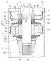
- the shock absorber D in one embodiment includes a cylinder 1, a rod 2 movably inserted into the cylinder 1, and two operating chambers provided in the cylinder 1. It is provided with a valve disk 3 having a port 3d for communicating the extension side chamber R1 and the compression side chamber R2, the extension side chamber R1 and the compression side chamber R2, and a leaf valve 4 for opening and closing the port 3d. Then, in the case of this shock absorber D, it is used by being interposed between the vehicle body and the axle in a vehicle (not shown), and the vibration of the vehicle body and the wheels is suppressed.
- an annular rod guide 20 is attached to the upper end of the cylinder 1, and the lower end of the cylinder 1 is closed by a cap 21.
- a rod 2 having a piston 5 and a valve disc 3 mounted on the tip thereof is movably inserted into the cylinder 1.
- the rod 2 is slidably inserted into the rod guide and inserted into the cylinder 1, and the rod guide 20 guides the movement in the axial direction.
- the inside of the cylinder 1 is divided into an extension side chamber R1 and a compression side chamber R2 filled with a liquid such as hydraulic oil by a piston 5 and a valve disc 3.
- a liquid such as water or an aqueous solution can also be used as the liquid.
- the air chamber G is partitioned in the cylinder 1 below the compression side chamber R2 by a free piston 6 slidably inserted into the cylinder 1. Then, when the rod 2 is axially displaced with respect to the cylinder 1, the air chamber G is expanded and contracted by the free piston 6 being displaced axially with respect to the cylinder 1 in accordance with the volume change of the rod 2 in the cylinder 1.
- the volume change of the air chamber G causes the volume of the rod 2 entering and exiting the cylinder 1 to be compensated.
- the shock absorber D is a so-called single cylinder type shock absorber, but may be configured as a return cylinder type shock absorber having a reservoir outside the cylinder 1.
- the rod 2 is formed by providing a small diameter portion 2a provided at the tip at the lower end in FIG. 1, a screw portion 2b provided at the outer periphery of the tip of the small diameter portion 2a, and a small diameter portion 2a.
- a portion 2c is provided, and an annular piston 5 and a valve disc 3 are mounted on the outer periphery of the small diameter portion 2a.
- the piston 5 is annular and is fixed to the outer circumference of the small diameter portion 2a, and the outer circumference is in sliding contact with the inner circumference of the cylinder 1. Further, the piston 5 includes a compression side main port 5a and an extension side main port 5b as main ports. The outer circumference of the valve disc 3 is in sliding contact with the inner circumference of the cylinder 1, and the valve disc 3 is provided with a port 3d. The piston 5 and the valve disc 3 cooperate with each other to divide the inside of the cylinder 1 into an extension side chamber R1 and a compression side chamber R2, and an intermediate chamber R3 is formed between the piston 5 and the valve disc 3.
- the intermediate chamber R3 is communicated with the compression side chamber R2 by the compression side main port 5a and the extension side main port 5b provided on the piston 5, and is communicated with the extension side chamber R1 by the port 3d provided on the valve disc 3. Therefore, the compression side main port 5a, the extension side main port 5b, the intermediate chamber R3, and the port 3d form a passage that communicates the extension side chamber R1 and the compression side chamber R2.
- the extension side main leaf valve 11 and the valve stopper 12 as the main leaf valve are fitted in this order.
- the valve disc holder 7, the valve adjusting shim 8, the inner peripheral seat 9, the compression side main leaf valve 10, the piston 5, the extension side main leaf valve 11 and the valve stopper 12 are attached to the step portion 2c and the screw portion 2b of the rod 2. It is sandwiched and fixed by the nut 13 to be screwed.
- valve disc 3 is loosely fitted around the outer periphery of the valve disc holder 7 so as to be movable in the axial direction
- leaf valve 4 is an annular leaf valve that opens both inside and outside in the present embodiment
- valve adjustment shim 8 has a valve disc 3. It is fitted to the outer circumference.
- the valve disc holder 7 includes a tubular portion 7a that fits on the outer periphery of the small diameter portion 2a of the rod 2, and a flange portion 7b provided on the outer periphery of the upper end of the tubular portion 7a in FIG.
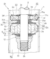
- the valve disc 3 is provided on the outer circumference of the annular main body 3a that is loosely fitted on the outer circumference of the cylinder 7a of the valve disc holder 7 and is provided on the outer circumference of the main body 3a and is in sliding contact with the inner circumference of the cylinder 1. It is provided with a sliding contact cylinder 3b, an annular window 3c provided at the leaf valve side end at the lower end of FIG.
- annular valve seat 3e is provided on the outer periphery of the annular window 3c at the lower middle end of FIG. 2 of the main body portion 3a of the valve disc 3.
- the annular valve seat 3e protrudes downward in FIG. 2 from the main body 3a, and is an annular valve seat from the upper end in FIG. 2 of the main body 3a from the axial length L2 on the inner peripheral side of the annular window 3c of the main body 3a.
- the axial length to the lower middle end of FIG. 2 of 3e is longer.
- the axial length L2 on the inner circumference of the main body 3a of the valve disc 3 with respect to the annular window 3c is the axial length from the middle lower end of FIG. 2 of the tubular portion 7a of the valve disc holder 7 to the middle lower end of FIG. 2 of the flange portion 7b. Shorter than the length L1, the valve disc 3 can move the outer circumference of the tubular portion 7a of the valve disc holder 7 in the axial direction by the difference ⁇ between the length L1 and the length L2.
- the valve disc 3 is attached to the rod 2 via the valve disc holder 7 in the present embodiment, but if a step portion is provided in addition to the step portion 2c on the outer circumference of the rod 2, the valve disc holder 7 is provided. Can be omitted.
- the inner peripheral diameter of the main body portion 3a of the valve disc 3 is larger than the outer peripheral diameter of the tubular portion 7a of the valve disc holder 7 and smaller than the outer peripheral diameter of the flange portion 7b.
- No. 3 can be displaced in the radial direction with respect to the valve disc holder 7 by the difference between the inner peripheral diameter and the outer peripheral diameter without falling off from the valve disc holder 7. That is, the valve disc 3 can be displaced in the radial direction with respect to the rod 2, and the degree of displacement in the radial direction is arbitrarily set on the condition that the generation of the damping force is not hindered.
- the valve adjustment shim 8 is annular and is fitted to the outer circumference of the small diameter portion 2a of the rod 2, and has a notch 8a on the outer circumference.
- the valve adjusting shim 8 is fitted on the outer circumference of the rod 2 and has an outer diameter larger than the outer diameter of the tubular portion 7 of the valve disc 7. Further, the valve adjusting shim 8 is laminated on the lower end of the tubular portion 7a of the valve disc holder 7 in FIG. 2, and the valve disc 3 loosely fitted on the outer circumference of the valve disc holder 7 comes into contact with the flange portion 7b. In the state, they face each other with a gap in the axial direction. Therefore, when the valve disc 3 moves downward in FIG. 2 from the state shown in FIG.
- valve adjusting shim 8 restricts the further downward movement of the valve disc 3. Functions as a stopper. Further, the leaf valve 4 fitted to the outer periphery of the valve adjusting shim 8 is centered by the valve adjusting shim 8 to restrict movement in the radial direction.
- the inner peripheral seat 9 is annular and is fitted to the outer periphery of the small diameter portion 2a of the rod 2.
- the outer peripheral diameter of the inner peripheral seat 9 is larger than the outer peripheral diameter of the valve adjusting shim 8, and the inner peripheral circumference of the lower middle lower end of FIG. 2 of the leaf valve 4 is seated on the outer peripheral diameter of the upper middle upper end of FIG. 2 of the inner peripheral seat 9. doing.
- the outer periphery of the upper end of the leaf valve 4 in FIG. 2 is seated on the annular valve seat 3e of the valve disc 3. As shown in FIG. 2, the axial position of the upper end of the inner peripheral seat 9 in FIG.
- FIG. 2 is the lower end of the annular valve seat 3e in a state where the upper end of the valve disc 3 is in contact with the flange portion 7b of the valve disc holder 7. It is located higher in FIG. 2 than the axial position. Therefore, when the leaf valve 4 is interposed between the inner peripheral seat 9 and the annular valve seat 3e, the leaf valve 4 is seated on the inner peripheral seat 9 and the annular valve seat 3e in a state of being bent by being given an initial deflection. Then, the valve disc 3 is urged in the direction of contact with the flange portion 7b. The axial position of the upper end in FIG.
- valve adjustment shim 8 laminated on the lower end of the tubular portion 7a of the valve disc holder 7 in FIG. It can be adjusted by the thickness which is the length in the vertical direction in FIG. Therefore, by changing the design of the thickness of the valve adjusting shim 8, the initial deflection amount, which is the magnitude of the initial deflection given to the leaf valve 4, can be changed.
- the leaf valve 4 closes the port 3d when seated on the inner peripheral seat 9 and the annular valve seat 3e, but when the pressure in the intermediate chamber R3 becomes higher than the pressure in the extension side chamber R1, the inner peripheral side flexes upward. Then, the port 3d is opened by leaving the inner peripheral seat 9, and conversely, when the pressure of the extension side chamber R1 becomes higher than the pressure of the intermediate chamber R3, the outer peripheral side bends downward and separates from the annular valve seat 3e to open the port. Open 3d.
- the gap between the inner circumference of the leaf valve 4 and the outer circumference of the valve adjustment shim 8 is reduced. However, if this is done, the area of the flow path formed by the gap when the inner circumference of the leaf valve 4 is separated from the inner circumference seat 9 is also reduced, and the liquid is given to the flow passing through the gap. The resistance may be excessive.
- the notch 8a is provided on the outer periphery of the valve adjusting shim 8, the notch 8a contributes to the flow path area when the inner peripheral side of the leaf valve 4 bends and leaves the inner peripheral seat 9.
- the flow path area when the valve is opened on the inner peripheral side of the valve 4 is secured, and it is possible to prevent the resistance from becoming excessive. Therefore, by providing the notch 8a on the outer periphery of the valve adjusting shim 8, it is possible to improve the alignment performance of the leaf valve 4 by the valve adjusting shim 8 and to secure the flow path area when the leaf valve 4 is opened. If the notch 8a is unnecessary, the notch 8a can be abolished.
- the compression side main leaf valve 10 is a laminated leaf valve formed by laminating a plurality of annular plates, and is overlapped on the upper end of FIG. 2 of the piston 5 to open and close the outlet end of the compression side main port 5a. ..
- An orifice 10a formed by a notch is provided on the outer periphery of the annular plate facing the piston 5 of the compression side main leaf valve 10.
- the extension side main leaf valve 11 is a laminated leaf valve formed by laminating a plurality of annular plates, and is overlapped with the lower middle end of FIG. 2 of the piston 5 to open and close the outlet end of the extension side main port 5b.
- An orifice 11a formed by a notch is provided on the outer periphery of the annular plate facing the piston 5 of the extension side main leaf valve 11.
- the shock absorber D is configured as described above, and the operation of the shock absorber D will be described below. First, the operation when the rod 2 moves upward in FIG. 1 with respect to the cylinder 1 and the shock absorber D is extended and operated will be described. When the shock absorber D is extended, the piston 5 and the valve disk 3 move upward in FIG. 1 with respect to the cylinder 1, so that the extension side chamber R1 is compressed and the compression side chamber R2 is expanded.
- the leaf valve 4 receives the pressure of the extension side chamber R1 and the outer peripheral side bends to separate from the annular valve seat 3e. And open port 3d.
- the valve disc 3 is displaced downward in FIG. 2 with respect to the valve disc holder 7 due to the pressure from the extension side chamber R1, but the amount of deflection of the outer periphery of the leaf valve 4 is larger than this displacement amount.
- An annular gap is formed between the leaf valve 4 and the annular valve seat 3e, and the port 3d is opened.
- the liquid in the extension side chamber R1 bends the outer circumference of the leaf valve 4, passes through the port 3d, passes through the intermediate chamber R3, passes through the main ports 5a and 5b and the orifices 10a and 11a on the compression side and the extension side, and passes through the compression side chamber. Move to R2.
- the extension speed of the shock absorber D is in the very low speed region during the extension operation, the flow rate passing through the orifices 10a and 11a is very small, so that when the liquid passes through the orifices 10a and 11a, The pressure loss that occurs when passing through the leaf valve 4 is larger than the pressure loss that occurs. Therefore, when the shock absorber D extends in a very low speed region, the leaf valve 4 mainly exerts a damping force.
- the extension side main leaf valve 11 does not open, but the pressure loss at the orifices 10a and 11a becomes large, so that the shock absorber D has the leaf valve 4 and the orifice 10a, The damping force is exerted by 11a.
- the extension side main leaf valve 11 bends and opens to greatly open the extension side main port 5b, and the shock absorber D mainly uses the leaf valve 4. And the extension side main leaf valve 11 exerts a damping force.
- the liquid in the compression side chamber R2 moves to the extension side chamber R1.
- the leaf valve 4 receives the pressure of the compression side chamber R2 and the inner peripheral side bends to separate from the inner peripheral seat 9. Then, an annular gap is formed between the leaf valve 4 and the inner peripheral seat 9, and the port 3d is opened.
- the liquid in the compression side chamber R2 passes through the main ports 5a and 5b on the compression side and the extension side, the orifices 10a and 11a, and the intermediate chamber R3, bends the inner circumference of the leaf valve 4, passes through the port 3d, and passes through the extension side chamber R1.
- the flow rate passing through the orifices 10a and 11a is very small, so that when the liquid passes through the orifices 10a and 11a,
- the pressure loss that occurs when passing through the leaf valve 4 is larger than the pressure loss that occurs. Therefore, when the shock absorber D contracts in a very low speed region, the leaf valve 4 mainly exerts a damping force.
- the pressure side main leaf valve 10 does not open, but the pressure loss at the orifices 10a and 11a becomes large, so that the shock absorber D has the leaf valve 4 and the orifices 10a and 11a. Demonstrate damping force.
- the compression side main leaf valve 10 bends and opens to greatly open the compression side main port 5a, and the shock absorber D mainly includes the leaf valve 4 and the compression side.
- the main leaf valve 10 exerts a damping force.
- the speed range in which the damping force is generated mainly by the leaf valve 4 is set to a very low speed
- the speed range in which the damping force is generated mainly by the orifices 10a and 11a is set to a low speed
- the speed range in which the damping force is generated by the compression side main leaf valve 10 or the extension side main leaf valve 11 is set to high speed.
- the designer can arbitrarily set the speed for classifying the very low speed, the low speed, and the high speed.
- either one of the orifices 10a and 11a can be omitted, and the orifices 10a and 11a may be provided on the piston 5 instead of the compression side main leaf valve 10 and the extension side main leaf valve 11.
- the compression side main leaf valve 10 and the extension side main leaf valve 11 do not open, and the leaf valve 4 opens and closes the port 3d.
- the valve disc 3 is affected by the pressure of the extension side chamber R1 during the extension operation. It is in a state of being separated from the flange portion 7b of the holder 7, and the outer periphery of the leaf valve 4 is in a state of being bent and separated from the annular valve seat 3e.
- the leaf valve 4 When the expansion / contraction direction of the shock absorber D changes from this state to contraction, the leaf valve 4 is affected by the compression side chamber R2 and returns to the position where it comes into contact with the annular valve seat 3e by its own restoring force, but the valve disk 3 is at the flange portion. Since it is separated from 7b, the impact of the leaf valve 4 colliding with the annular valve seat 3e is not transmitted to the rod 2.
- the impact generated when the leaf valve 4 separated from the annular valve seat 3e is seated on the annular valve seat 3e is not transmitted to the rod 2, so that the vibration is transmitted to the vehicle body by that amount. You don't have to give it.
- the shock absorber D of the present embodiment includes the cylinder 1, the rod 2 movably inserted into the cylinder 1, the extension side chamber (operating chamber) R1 provided in the cylinder 1, and the compression side chamber (operation).
- Chamber) R2 and the extension side chamber (operating chamber) R1 and the compression side chamber (operating chamber) R2 which are provided on the outer periphery of the rod 2 so as to be movable in the axial direction and are opened on the inner circumferences of the annular valve seat 3e and the annular valve seat 3e.
- a valve disk 3 having a port 3d communicating with the port 3d and an annular leaf valve 4 for opening and closing the port 3d are provided.
- the shock absorber D configured in this way, since the valve disc 3 can move in the axial direction with respect to the rod 2, the impact generated when the leaf valve 4 is seated from the state separated from the annular valve seat 3e is applied to the rod 2. It is possible to suppress the transmission and suppress the vibration to the vehicle body. Therefore, according to the shock absorber D of the present embodiment, it is possible to suppress the vibration of the vehicle body, so that the rattling noise can be eliminated and the riding comfort in the vehicle can be improved.
- the valve disc 3 is urged in the axial direction with the leaf valve 4 seated on the annular valve seat 3e, and the valve disc 3 is in the urging direction of the leaf valve 4. Can be returned to its original position (the position where the valve disc 3 abuts on the flange portion 7b of the valve disc holder 7) even if it moves in the opposite direction, and the port 3d is blocked regardless of the position of the valve disc 3. There is no problem that it cannot be done and remains open.
- the shock absorber D configured in this way, the damping force as set can be exhibited even if the shock absorber D expands and contracts at a very low speed, and there is no possibility that the damping force is insufficient and the riding comfort is deteriorated.
- the leaf valve 4 is annular, and one of the inner side and the outer side is opened with respect to the flow of liquid from one working chamber to the other working chamber, and the other is activated. Since it is a leaf valve that opens both inside and outside, with the other inside and outside opening for the flow of liquid from the chamber to one operating chamber, a single leaf valve 4 can exert damping force on both sides of expansion and contraction. The total length of the piston portion can be shortened, and the stroke length of the shock absorber D can be easily secured accordingly.
- the leaf valve 4 opens on the outer peripheral side with respect to the flow of liquid from the extension side chamber R1 to the compression side chamber R2, and with respect to the flow of liquid from the compression side chamber R2 to the extension side chamber R1.
- the valve is opened on the inner peripheral side, but the design can be arbitrarily changed as to whether the inner circumference or the outer circumference of the leaf valve 4 is opened with respect to the flow direction.
- the leaf valve 4 may be a laminated leaf valve formed by laminating a plurality of annular plates.
- the leaf valve 4 is arranged on the lower intermediate chamber R3 side in FIG. 2 of the valve disc 3, but is arranged on the upper extension side chamber R1 side in FIG. 2 of the valve disc 3. May be good.
- the valve disc holder 7 is arranged upside down from the position shown in FIG. 2, and the valve adjustment shim 8 and the inner peripheral seat 9 are arranged together with the leaf valve 4 in the upper part of FIG. 2 of the valve disc holder 7. do it.
- an annular valve adjustment shim mounted on the outer circumference of the rod 2 and facing the valve disc 3 in the axial direction with a gap is provided and arranged on the inner peripheral side of the leaf valve 4. Equipped with 8. According to the shock absorber D configured in this way, not only the adjustment of the initial deflection amount given to the leaf valve 4 by the valve adjustment shim 8 but also the function as a stopper for restricting the movement of the valve disc 3 is performed. It can be integrated into the valve adjustment shim 8, the number of parts can be reduced, and the cost can be reduced.
- the facing surface of the valve adjusting shim 8 facing the valve disc 3 in the axial direction is a contact surface capable of contacting the valve disc 3, and a step portion is formed on the outer periphery of the valve adjusting shim 8 to form a step portion. If the contact surface is set to, the position of the contact surface can be adjusted up and down in FIG. 2 by changing the design of the valve adjustment shim 8.
- the compression side main port 5a and the extension side main port 5a as the main port fixed to the outer periphery of the rod 2 and communicating the extension side chamber (operating chamber) R1 and the compression side chamber (operating chamber) R2.
- a piston 5 having a side main port 5b and slidingly contacting the inner circumference of the cylinder 1, and a compression side main leaf valve as a main valve that is mounted on the outer circumference of the rod 2 to open and close the compression side main port 5a and the extension side main port 5b.
- 10 and the extension side main leaf valve 11 are provided, and the valve disc 3 is in sliding contact with the inner circumference of the cylinder 1 and is allowed to move in the radial direction with respect to the valve disc holder 7.
- the rod 2 and the cylinder 1 are positioned in the radial direction by the piston 5, but the valve disc 3 can move in the radial direction with respect to the rod 2, so that the piston 5 and the cylinder 1 can be moved in the radial direction. Even if there is a dimensional error in the rod 2 or the valve disc 3, the sliding resistance between the valve disc 3 and the cylinder 1 does not increase. Therefore, according to the shock absorber D configured in this way, even if the structure in which the piston 5 and the valve disk 3 are in sliding contact with the cylinder 1 is adopted, the sliding resistance does not increase and the valve disk 3 can be smoothly expanded and contracted, and has a high degree of dimension. Costs are also reduced because management is not required.
- valve disc 3 Even when the valve disc 3 is slidably contacted with the guide cylinder 5c of the cylinder 1 or the piston 5, the valve disc 3 will not be loosely fitted to the outer circumference of the valve disc holder 7 or the rod 2 if the dimensions are controlled accurately. It may be made to slide in contact with.
- the outer circumference of the valve disc 3 is not slidably contacted with the inner circumference of the cylinder 1, but is directed downward toward the outer circumference of the lower end of FIG. 3 of the piston 5.
- a protruding guide cylinder 5c may be provided, and the valve disc 3 may be arranged on the lower side of the piston 5 so as to be slidably contacted with the inner circumference of the guide cylinder 5c.
- the valve disc holder 7, the valve adjustment shim 8, the leaf valve 4 and the inner peripheral seat 9 are laminated below the extension side main leaf valve 11, and the piston 5 and the valve are located below the piston 5 in FIG.
- the gap surrounded by the disk 3 may be the intermediate chamber R3.
- the guide cylinder 5c may be a separate part from the piston 5.
- the shock absorber D1 of the second modification has the structure of the shock absorber D1 shown in FIG. 2 on the anti-valve disk side of the valve adjustment shim 8 instead of the inner peripheral seat 9.
- a leaf valve 22 having a valve holder 23 and a spacer 21 supported by the valve holder 23, and a first disk 22a and a second disk 22b instead of the leaf valve 4 is provided.
- the valve holder 23 is annular and is fitted to the outer circumference of the rod 2 in a state of being laminated on the anti-valve disc side of the valve adjustment shim 8, and has a shape in which the outer diameter is two-step larger. Is provided with a small diameter portion 23a, a medium diameter portion 23b, and a large diameter portion 23c from the valve disc side. The leaf valve 22 and the spacer 21 are sequentially fitted to the outer periphery of the small diameter portion 23a of the valve holder 23.
- valve holder 23 When the valve holder 23 is laminated on the valve adjustment shim 8, the inner circumference of the first disk 22a of the leaf valve 22 arranged between the spacer 21 and the valve adjustment shim 8 is formed by the valve adjustment shim 8 and the spacer 21. Be pinched.
- the valve holder 23 plays a role of aligning the radial positions of the leaf valve 22 and the spacer 21, but the inner circumferences of the spacer 21 and the leaf valve 22 are directly fitted to the outer circumference of the rod 2. In that case, the valve holder 23 may be abolished.
- the leaf valve 22 is annular and is fitted to the outer circumference of the small diameter portion 23a of the inner circumference valve holder 23, and the inner circumference is sandwiched between the valve tension shim 8 and the spacer 21 to allow bending on the outer circumference side. It includes a first disc 22a to be formed, and a second disc 22b which is annular and is attached to the side surface of the valve disc of the first disc 22a.
- the inner diameter of the first disc 22a is smaller than the outer diameter of the valve tone shim 8 and the spacer 21, and the outer diameter is larger than the outer diameter of the valve adjusting shim 8 and the spacer 21.
- the diameter is set so that it can be taken off and seated on the annular valve seat 3e of the above, and the inner circumference is seated on the annular valve seat 3e in a state of being sandwiched between the valve adjusting shim 8 and the spacer 21.
- the first disk 22a bends under the pressure of the extension side chamber R1, it separates from the annular valve seat 3e and opens the port 3d to give resistance to the flow of liquid from the extension side chamber R1 to the compression side chamber R2.
- the first disk 22a can be detached and seated on the annular valve seat 3e to open and close the port 3d. Further, the first disk 22a is provided with a communication hole 22a1 that penetrates the wall thickness in the axial direction.
- the valve holder 23 plays a role of aligning the radial positions of the leaf valve 22 and the spacer 21, and when the first disc 22a is bent to the maximum, the valve holder 23 has a medium diameter on the side surface of the anti-valve disc of the first disc 22a. It also functions as a valve stopper that supports the first disk 22a by abutting the outer peripheral edge of the portion 23b.
- the second disc 22b is annular and has an inner diameter larger than the outer diameter of the valve adjusting shim 8 and an outer diameter smaller than the inner diameter of the annular valve seat 3e and is laminated on the side surface of the valve disc of the first disc 22a.
- the outer circumference is attached to the outer circumference side of the first valve disc 22a by welding or the like. Further, the second disk 22b is attached to the first disk 22a at a position that closes the communication hole 22a1, and when the whole is in contact with the first disk 22a, the communication hole 22a1 is closed and the communication hole 22a1 is closed.
- the inner peripheral side bends upward in FIG. 4 to open the communication hole 22a1.
- the second disk 22b is allowed to bend on the inner peripheral side with respect to the first disk 22a, and the communication hole 22a1 can be opened and closed.
- the second disk 22b opens the communication hole 22a1 with respect to the flow from the compression side chamber R2 to the extension side chamber R1 in the direction opposite to the flow of the liquid when the first disk 22a opens the port 3d. Gives resistance to the flow of.
- the shock absorber D1 configured in this way, when the liquid flows from the extension side chamber R1 to the compression side chamber R2, the second disk 22b in the leaf valve 22 is pressed against the first disk 22a to close the communication hole 22a1.
- the outer circumference of the first disk 22a is bent to open the port 3d. Therefore, when the liquid moves from the extension side chamber R1 to the compression side chamber R2, the liquid passes through the annular gap formed between the first disk 22a and the annular valve seat 3e and moves from the extension side chamber R1 to the compression side chamber R2. ..
- the magnitude of the resistance that the liquid receives when passing through the annular gap changes depending on the size of the annular gap, and the size of the annular gap depends on the flexural rigidity of the first disk 22a and the diameter of the annular gap. Change.
- the size of the annular gap increases as the diameter of the annular gap increases and as the deflection rigidity of the first disk 22a decreases.
- the outer diameter of the spacer 21 which is the fulcrum of the deflection of the first disk 22a is set. If the diameter is made as small as possible, the inner diameter of the annular valve seat 3e is made as large as possible, and the size of the annular gap between the annular valve seat 3e and the first disk 22a is increased with respect to the amount of deflection of the first disk 22a. Good.
- the shock absorber D1 contracts and the first disk Since the annular gap formed between the leaf valve 22 and the annular valve seat 3e when the 22a is bent becomes large, the resistance given to the liquid flow by the leaf valve 22 can be minimized.
- the shock absorber D1 of the present embodiment when the liquid flows from the compression side chamber R2 to the extension side chamber R1, the first disk 22a in the leaf valve 22 is pressed against the annular valve seat 3e of the valve disk 3 to block the port 3d.
- the second disk 22b receives the pressure of the compression side chamber R2 from the communication hole 22a1 and bends the inner circumference to open the communication hole 22b so that the compression side chamber R2 and the port 3d communicate with each other. In this way, when the liquid goes from the compression side chamber R2 to the extension side chamber R1, the second disk 22b provides resistance to the flow of the liquid.
- the magnitude of the damping force when the liquid bends the second disc 22b and passes through the communication hole 22a1 is not related to the bending rigidity of the first disc 22a, and when the inner circumference of the second disc 22b bends. It depends on the size of the annular gap between the inner circumference of the second disk 22b and the first disk 22a. Since the inner and outer diameter difference and the deflection rigidity of the second disk 22a can be set independently of the first disk 22a, the damping force when the second disk 22b is bent and passes through the communication hole 22a1 is the first disk. It can be set separately regardless of the setting of 22a.
- the size of the annular gap between the inner circumference of the second disc 22b and the first disc 22a increases as the diameter of the annular gap increases and as the bending rigidity of the second disc 22b decreases. Therefore, if the inner circumference of the second disc 22b is increased and the bending rigidity of the second disc 22b is reduced, the inner circumference of the second disc 22b when the shock absorber D contracts and the second disc 22b bends. Since the annular gap formed between the first disk 22a and the first disk 22a becomes large, the resistance given to the flow of the liquid by the leaf valve 22 can be minimized.
- the damping force when the second disk 22b is opened and the liquid passes through is reduced.
- the damping force generated in the second disk 22b can be set relatively freely, although there are some restrictions depending on the position of the communication hole 22a1 and the outer diameter of the first disk 22a.
- the shock absorber D1 of the present embodiment is mounted on the outer periphery of the rod 2 and faces the valve disc 3 in the axial direction with a gap, and is arranged on the valve disc side of the leaf valve 22 to adjust the annular valve.
- a shim 8 and an annular spacer 21 mounted on the outer periphery of the rod 2 and sandwiching the inner circumference of the leaf valve 22 together with the valve adjusting shim 8 are provided, and the leaf valve 22 has a communication hole 22a1 leading to the port 3d.
- the first disk 22a which is set to open outward, and the ring-shaped first disk 22a, which is overlapped on the valve disk side, opens and closes the communication hole 22a1 and has an inner diameter larger than that of the first disk 22a.
- a second disk 22b is provided.
- the valve adjusting shim 8 is mounted on the outer periphery of the rod 2 and faces the valve disc 3 with a gap in the axial direction, and the valve disc 3 is located in the lower part of FIG.
- the valve adjusting shim 8 functions as a stopper that restricts further downward movement of the valve disc 3.
- the fixed position on the inner peripheral side of the leaf valve 22 overlapped on the anti-valve disc side of the valve adjusting shim 8 can be changed by changing the thickness of the valve adjusting shim 8. Therefore, by changing the design of the thickness of the valve adjusting shim 8, the initial deflection amount, which is the magnitude of the initial deflection given to the first disk 22a of the leaf valve 22, can be changed.
- shock absorber D1 configured in this way, not only the adjustment of the initial deflection amount given to the leaf valve 22 by the valve adjustment shim 8 but also the function as a stopper for restricting the movement of the valve disc 3 is performed.
- the functions can be integrated into the valve adjustment shim 8, the number of parts can be reduced, and the cost can be reduced.
- the shock absorber D1 configured in this way, even if the first disk 22a opens the port 3d to reduce the damping force when the liquid passes through the outer periphery of the leaf valve 22, the second disk 22b Since the damping force when the liquid passes by opening is not increased and can be set freely, it is possible to reduce the damping force on both sides of the extension. From the above, according to the shock absorber D1 of the present embodiment, the damping force on both sides of the expansion force can be reduced.
- the damping force when the liquid passes through the outer periphery of the leaf valve 22 by opening the port 3d is the bending rigidity of the first disk 22a and the outside of the spacer 21. It can be adjusted by setting the diameter and the outer diameter of the annular valve seat 3e, and the damping force when the second disc 22b opens and the liquid passes through can be adjusted by setting the inner and outer diameter difference and the inner diameter of the second disc 22b. Since it can be adjusted independently, the damping force on the extension side and the damping force on the compression side can be set independently.
- the damping force when the liquid passes through the outer periphery of the leaf valve 22 by opening the port 3d is the bending rigidity of the first disk 22a and the second disk 22b, the outer diameter of the spacer 21, and the annular valve seat 3e.
- the damping force when the second disc 22b opens and the liquid passes through can be adjusted by setting the inner and outer diameters of the second disc 22b, so the damping force on the extension side and the compression side can be adjusted. Damping force can be set individually.
- first disk 22a and the second disk 22b are both composed of a single annular plate, they may be composed of a plurality of annular plates that are laminated together.
- the outer circumferences of these annular plates may be welded and integrated with the first disc 22a.
- the outer diameter of the second disc 2 is smaller than the outer diameter of the first disc 22a, but the outer diameters of the first disc 22a and the second disc 22b are set to be the same and the second disc 22b. May be seated on the annular valve seat 3e.
- the difference between the inner and outer diameters of the second disc 22b can be increased, which is advantageous in reducing the bending rigidity and the damping force can be further reduced.
- the valve disc holder 7, the valve adjusting shim 8, the leaf valve 22, and the spacer 21 in the shock absorber D1 are arranged in the opposite directions to those shown in FIG.
- the second disk 22b may open the communication hole 22a1 with respect to the flow of the liquid
- the first disk 22a may open the port 3d with respect to the flow of the liquid from the opposite compression side chamber R2 to the extension side chamber R1.
- the leaf valve 22 has a structure in which the first disk 22a and the second disk 22b are laminated, but the leaf valve 22 in FIG. 4 may be changed to the leaf valve 4 in FIG.
- the leaf valve 4 since the inner circumference of the leaf valve 4 is sandwiched between the valve adjusting shim 8 and the spacer 21, the leaf valve 4 is in a mode in which the outer circumference is allowed to bend and swallow, but even in this case, the valve adjusting shim 8 functions as a stopper for the valve disc 3 and can exert a function of adjusting the initial deflection amount of the leaf valve 4.
- the shock absorber When the shock absorber is configured in this way, if it is desired that the liquid can move the port 3d from the extension side chamber R1 to the compression side chamber R2 and from the compression side chamber R2 to the extension side chamber R1, the leaf valve 4 or the annular valve seat An orifice or a choke may be provided in 3e.
- the leaf valve 4 that opens both inside and outside is provided either above or below the valve disc 3, but is like the shock absorber D2 of the third modification shown in FIG.
- the leaf valves 4a and 4b on the extension side and the compression side may be provided above and below the valve disc 31, respectively.
- the valve disc 31 has a perforated disk shape, and the annular windows 31a and 31b provided at the upper and lower ends in FIG. 5, respectively, and the annular valve seats 31c and 31d surrounding the outer circumferences of the annular windows 31a and 31b.
- a first port 31e that opens from the outer circumference of the lower end annular valve seat 31d and leads to the upper end annular window 31a
- a second port 31f that opens from the outer circumference of the upper end annular valve seat 31c and leads to the lower end annular window 31b.
- the valve disc 31 is loosely fitted on the outer circumference of the tubular collar 32 fitted to the outer circumference of the rod 2, and is allowed to move in the radial direction with respect to the rod 2.
- the first leaf valve 4a whose inner circumference is fixed to the rod 2 and the spacer 33 are laminated on the upper part of FIG. 5 of the collar 32, and the inner circumference of the collar 32 is also a rod in the lower part of FIG.
- the second leaf valve 4b fixed to 2 and the spacer 34 are laminated.
- the axial length of the inner peripheral side of the valve disc 31 is shorter than the axial length of the collar 32, and the valve disc 31 can move in the axial direction with respect to the rod 2 in the same manner as the valve disc 3.
- the outer circumference of the first leaf valve 4a is detached and seated on the annular valve seat 31c on the upper end side in FIG. 5 of the valve disc 31 to open and close the first port 31e.
- the outer circumference of the second leaf valve 4b opens and closes the second port 31f by taking off and seating on the annular valve seat 31d on the lower end side of FIG. 5 of the valve disc 31.
- the axial length from the upper end of the annular valve seat 31c of the valve disc 31 to the lower end of the annular valve seat 31d is longer than the axial length of the collar 32, and the first leaf valve 4a is seated on the annular valve seat 31c.
- the first leaf valve 4a and the second leaf valve 4b bend to urge the valve disc 31 from above and below. Since the initial deflection is given to the first leaf valve 4a and the second leaf valve 4b in this way, the valve disc 31 is urged by both the first leaf valve 4a and the second leaf valve 4b, and both of them are urged. It is positioned at a position where the urging force is balanced.
- the shock absorber D2 in the third modification generates a damping force by the second leaf valve 4b and the orifices 10a and 11a when extending at a low speed, and mainly when extending at a high speed.
- a damping force is generated by the extension side main leaf valve 11.
- the shock absorber D2 in the third modification of one embodiment contracts at a very low speed
- the first leaf valve 4a bends and the valve disc 31 moves upward in FIG. 5 due to the action of the pressure of the compression side chamber R2.
- the first leaf valve 4a separates from the annular valve seat 31d and the first port 31e is opened. Therefore, the liquid in the compression side chamber R2 moves to the extension side chamber R1 via the first port 31e, and the first port 31e allows only the flow of the liquid from the compression side chamber R2 to the extension side chamber R1.
- a damping force is generated by the first leaf valve 4a.
- the shock absorber D2 in the third modification generates a damping force by the first leaf valve 4a and the orifices 10a and 11a when contracting at a low speed, and mainly when extending at a high speed.
- a damping force is generated by the compression side main leaf valve 10.
- the compression side main leaf valve 10 and the extension side main leaf valve 11 do not open, and the first port valve 4a and the second leaf valve 4b correspond to the first port 31e. And the second port 31f is opened and closed.
- the valve disc 31 is affected by the pressure of the extension side chamber R1 during the extension operation. Moving inward and downward, the outer circumference of the second leaf valve 4b bends and is separated from the annular valve seat 31d.
- the second leaf valve 4b When the expansion / contraction direction of the shock absorber D2 changes from this state to contraction, the second leaf valve 4b is affected by the compression side chamber R2 and returns to the position where it comes into contact with the annular valve seat 31d by its own restoring force, but the valve disk 31 is moved. Since it is separated from the inner circumference of the first leaf valve 4a, the impact of the second leaf valve 4b colliding with the annular valve seat 31d is not transmitted to the rod 2.
- valve disc 31 is moved upward in FIG. 5 by the action of the pressure of the compression side chamber R2 during the contraction operation.
- the outer circumference of the first leaf valve 4a is bent and separated from the annular valve seat 31c.
- the first leaf valve 4a When the expansion / contraction direction of the shock absorber D2 changes from this state to extension, the first leaf valve 4a is affected by the extension side chamber R1 and returns to the position where it comes into contact with the annular valve seat 31c by its own restoring force, but the valve disc 31 Since it is separated from the inner circumference of the second leaf valve 4b, the impact of the first leaf valve 4a colliding with the annular valve seat 31c is not transmitted to the rod 2.
- the impact generated when the first leaf valve 4a or the second leaf valve 4b separated from the annular valve seats 31c and 31d is seated on the annular valve seats 31c and 31d is the rod 2. Since it is not transmitted to the vehicle body, it is not necessary to give vibration to the vehicle body.
- the port provided on the valve disk 31 is from one compression side chamber (working chamber) R2 to the other extension side chamber (working chamber) R1. It has a first port 31e provided for a flowing liquid and a second port 31f provided for a flow of liquid from the other extension chamber (operating chamber) R1 to the one compression side chamber (operating chamber) R2.
- the leaf valve is arranged on the upper end side in FIG. 5 which is one end side in the axial direction of the valve disc 31, and is the first leaf valve 4a which opens and closes the first port 31e and the other end side in the axial direction of the valve disc 31.
- FIG. 5 A view in which a second leaf valve 4b arranged on the lower middle and lower ends side to open and close the second port 31f is provided, and the valve disc 31 is on both ends in the axial direction of the first leaf valve 4a and the second leaf valve 4b. 5 It is urged from the upper and lower sides.
- the shock absorber D2 configured in this way, since the valve disc 31 can move in the axial direction with respect to the rod 2, the first leaf valve 4a and the second leaf valve 4b correspond to the annular valve seat 31c and the annular valve seat 31d. It is possible to suppress the impact generated when sitting from a state separated from the rod 2 being transmitted to the rod 2, and it is possible to suppress the vibration to the vehicle body. That is, in the shock absorber D2 in the third modification, the transmission of vibration to the rod 2 can be suppressed at the time of switching from the extension operation to the contraction operation and at the time of switching from the contraction operation to the extension operation. It is possible to suppress the generation of sound and improve the riding comfort.
- the valve disc 31 moves in the axial direction. Can be returned to its original position (the position where the urging forces of the first leaf valve 4a and the second leaf valve 4b are balanced), and the first port 31e and the second port 31f can be returned to any position of the valve disc 31. There is no problem that the valve cannot be blocked and remains open. Therefore, according to the shock absorber D2 configured in this way, the damping force as set can be exhibited even if the shock absorber D2 expands and contracts at a very low speed, and there is no possibility that the damping force is insufficient and the riding comfort is deteriorated.
- the second leaf valve 4b generates a damping force when the extension operation is performed at a very low speed
- the first leaf valve 4a generates a damping force when the contraction operation is performed at a very low speed.
- the damping force during extension operation and the damping force during contraction operation can be set separately and independently.
- first disk 22a1 ... communication hole, 22b ... second disk, b31e ... first port, 31f ... second port, D, D1, D2 ... shock absorber, R1 ⁇ ⁇ ⁇ Extension side chamber (working chamber), R2 ⁇ ⁇ ⁇ Compression side chamber (working chamber)
Landscapes
- Engineering & Computer Science (AREA)
- General Engineering & Computer Science (AREA)
- Mechanical Engineering (AREA)
- Fluid-Damping Devices (AREA)
Priority Applications (4)
| Application Number | Priority Date | Filing Date | Title |
|---|---|---|---|
| JP2021554164A JP7329063B2 (ja) | 2019-10-30 | 2020-09-17 | 緩衝器 |
| DE112020005357.1T DE112020005357T5 (de) | 2019-10-30 | 2020-09-17 | Stossdämpfer |
| US17/630,783 US12595833B2 (en) | 2019-10-30 | 2020-09-17 | Shock absorber |
| CN202080073732.7A CN114585827B (zh) | 2019-10-30 | 2020-09-17 | 缓冲器 |
Applications Claiming Priority (2)
| Application Number | Priority Date | Filing Date | Title |
|---|---|---|---|
| JP2019-196923 | 2019-10-30 | ||
| JP2019196923 | 2019-10-30 |
Publications (1)
| Publication Number | Publication Date |
|---|---|
| WO2021084956A1 true WO2021084956A1 (ja) | 2021-05-06 |
Family
ID=75714489
Family Applications (1)
| Application Number | Title | Priority Date | Filing Date |
|---|---|---|---|
| PCT/JP2020/035183 Ceased WO2021084956A1 (ja) | 2019-10-30 | 2020-09-17 | 緩衝器 |
Country Status (5)
| Country | Link |
|---|---|
| US (1) | US12595833B2 (https=) |
| JP (1) | JP7329063B2 (https=) |
| CN (1) | CN114585827B (https=) |
| DE (1) | DE112020005357T5 (https=) |
| WO (1) | WO2021084956A1 (https=) |
Cited By (1)
| Publication number | Priority date | Publication date | Assignee | Title |
|---|---|---|---|---|
| WO2023176117A1 (ja) * | 2022-03-16 | 2023-09-21 | Kyb株式会社 | 減衰バルブおよび緩衝器 |
Families Citing this family (6)
| Publication number | Priority date | Publication date | Assignee | Title |
|---|---|---|---|---|
| US12595833B2 (en) * | 2019-10-30 | 2026-04-07 | Kyb Corporation | Shock absorber |
| TR2022018869A2 (tr) * | 2022-12-08 | 2023-01-23 | Maysan Mando Otomotiv Parcalari Sanayi Ve Ticaret Anonim Sirketi | Kovan ve kanal yapisina sahi̇p ayarlanabi̇li̇r sönümleme özelli̇ği̇ olan hi̇droli̇k sikiştirma durdurucu pi̇ston terti̇bati |
| EP4421348A1 (en) * | 2023-02-27 | 2024-08-28 | BeijingWest Industries Co. Ltd. | Damper assembly with clamped frequency dependent valve |
| US12319419B2 (en) | 2023-09-25 | 2025-06-03 | General Electric Company | Fluid-filled thrust link apparatus and associated method |
| US12509999B2 (en) * | 2023-09-25 | 2025-12-30 | General Electric Company | Viscous damper apparatus and associated methods to control a response to a resonant vibration frequency |
| US12529323B2 (en) | 2023-09-25 | 2026-01-20 | General Electric Company | Variable diameter thrust link apparatus |
Citations (4)
| Publication number | Priority date | Publication date | Assignee | Title |
|---|---|---|---|---|
| JPH0298234U (https=) * | 1988-04-22 | 1990-08-06 | ||
| JPH11280819A (ja) * | 1998-01-29 | 1999-10-15 | Toyota Motor Corp | ショックアブソ―バ |
| JP2002106624A (ja) * | 2000-08-23 | 2002-04-10 | Mannesmann Sachs Ag | 振動ダンパー用ピストン |
| JP2007211909A (ja) * | 2006-02-10 | 2007-08-23 | Kayaba Ind Co Ltd | 緩衝器のバルブ構造および緩衝器 |
Family Cites Families (31)
| Publication number | Priority date | Publication date | Assignee | Title |
|---|---|---|---|---|
| US2711797A (en) * | 1952-10-17 | 1955-06-28 | Ford Motor Co | Power steering device of the hydraulic type |
| DE1505478A1 (de) * | 1965-10-29 | 1969-09-25 | Bilstein August Fa | Stufenlos verstellbarer Stossdaempfer,insbesondere fuer Kraftfahrzeuge |
| DE2628893C2 (de) * | 1976-06-26 | 1981-11-26 | Volkswagenwerk Ag, 3180 Wolfsburg | Ventilanordnung für einen Schwingungsdämpfer |
| GB1550815A (en) * | 1976-06-29 | 1979-08-22 | Woodhead Ltd Jonas | Piston assemblies for hydraulic shock absorbers |
| GB1512884A (en) * | 1977-02-16 | 1978-06-01 | Girling Ltd | Telescopic damper units |
| JPS5527516A (en) * | 1978-08-14 | 1980-02-27 | Kayaba Ind Co Ltd | Damping force generating structure for use in hydraulic shock absorber |
| JPS55163344A (en) * | 1979-06-04 | 1980-12-19 | Kayaba Ind Co Ltd | Shock absorber |
| JPS5620846A (en) * | 1979-07-25 | 1981-02-26 | Kayaba Ind Co Ltd | Damping valve for hydraulic shock absorber |
| JPS56116940A (en) * | 1980-02-20 | 1981-09-14 | Tokico Ltd | Damping-force generating mechanism of hydraulic buffer |
| JPS58221032A (ja) * | 1982-06-18 | 1983-12-22 | Tokico Ltd | シリンダ装置 |
| JPS58211037A (ja) * | 1982-05-31 | 1983-12-08 | Nissan Motor Co Ltd | シヨツクアブソ−バ |
| JP2980744B2 (ja) | 1991-08-30 | 1999-11-22 | カヤバ工業株式会社 | ショックアブソーバのバルブ構造 |
| DE19729289B4 (de) * | 1997-07-09 | 2010-02-18 | Zf Sachs Ag | Dämpfventil für einen hydropneumatischen Schwingungsdämpfer |
| JP4587089B2 (ja) | 2000-05-31 | 2010-11-24 | 日立オートモティブシステムズ株式会社 | 減衰力調整式油圧緩衝器 |
| DE10326482A1 (de) * | 2003-06-10 | 2005-01-05 | Suspa Holding Gmbh | Dämpfer |
| JP2009085245A (ja) | 2007-09-27 | 2009-04-23 | Showa Corp | 油圧緩衝器の減衰力調整構造 |
| JP5438487B2 (ja) | 2009-12-11 | 2014-03-12 | カヤバ工業株式会社 | 緩衝装置 |
| EP2511563A4 (en) | 2009-12-11 | 2017-12-13 | KYB Corporation | Shock-absorbing device |
| US8627933B2 (en) * | 2010-06-01 | 2014-01-14 | Tenneco Automotive Operating Company Inc. | Two stage valve and hydraulic damped valve |
| KR101239911B1 (ko) * | 2011-01-18 | 2013-03-06 | 주식회사 만도 | 쇽업소버의 밸브구조 |
| JP5826595B2 (ja) | 2011-10-31 | 2015-12-02 | 株式会社ショーワ | 油圧緩衝器のバルブ構造 |
| JP5876806B2 (ja) * | 2012-09-27 | 2016-03-02 | Kyb株式会社 | 緩衝器 |
| JP5949789B2 (ja) | 2014-01-10 | 2016-07-13 | トヨタ自動車株式会社 | ショックアブソーバ |
| WO2016067724A1 (ja) | 2014-10-31 | 2016-05-06 | 日立オートモティブシステムズ株式会社 | 緩衝器 |
| CN107642575B (zh) * | 2017-11-02 | 2023-11-24 | 华东交通大学 | 一种汽车双筒式减振器 |
| JP2019196923A (ja) | 2018-05-07 | 2019-11-14 | 住友金属鉱山株式会社 | 可燃性ガスを含むガス分析装置用ガスサンプリング装置 |
| JP2019219292A (ja) * | 2018-06-20 | 2019-12-26 | パイオニア株式会社 | 測距装置 |
| US12595833B2 (en) * | 2019-10-30 | 2026-04-07 | Kyb Corporation | Shock absorber |
| JP2025116940A (ja) * | 2024-01-30 | 2025-08-12 | キヤノン株式会社 | 撮像システム |
| JP2025163344A (ja) * | 2024-04-17 | 2025-10-29 | 株式会社多摩川電子 | 水中音響測位システム |
| JP2026020846A (ja) * | 2024-07-29 | 2026-02-10 | Tdk株式会社 | コイル装置 |
-
2020
- 2020-09-17 US US17/630,783 patent/US12595833B2/en active Active
- 2020-09-17 WO PCT/JP2020/035183 patent/WO2021084956A1/ja not_active Ceased
- 2020-09-17 DE DE112020005357.1T patent/DE112020005357T5/de active Pending
- 2020-09-17 JP JP2021554164A patent/JP7329063B2/ja active Active
- 2020-09-17 CN CN202080073732.7A patent/CN114585827B/zh active Active
Patent Citations (4)
| Publication number | Priority date | Publication date | Assignee | Title |
|---|---|---|---|---|
| JPH0298234U (https=) * | 1988-04-22 | 1990-08-06 | ||
| JPH11280819A (ja) * | 1998-01-29 | 1999-10-15 | Toyota Motor Corp | ショックアブソ―バ |
| JP2002106624A (ja) * | 2000-08-23 | 2002-04-10 | Mannesmann Sachs Ag | 振動ダンパー用ピストン |
| JP2007211909A (ja) * | 2006-02-10 | 2007-08-23 | Kayaba Ind Co Ltd | 緩衝器のバルブ構造および緩衝器 |
Cited By (2)
| Publication number | Priority date | Publication date | Assignee | Title |
|---|---|---|---|---|
| WO2023176117A1 (ja) * | 2022-03-16 | 2023-09-21 | Kyb株式会社 | 減衰バルブおよび緩衝器 |
| JP2023135678A (ja) * | 2022-03-16 | 2023-09-29 | Kyb株式会社 | 減衰バルブおよび緩衝器 |
Also Published As
| Publication number | Publication date |
|---|---|
| JP7329063B2 (ja) | 2023-08-17 |
| CN114585827A (zh) | 2022-06-03 |
| JPWO2021084956A1 (https=) | 2021-05-06 |
| US12595833B2 (en) | 2026-04-07 |
| US20220268335A1 (en) | 2022-08-25 |
| DE112020005357T5 (de) | 2022-08-11 |
| CN114585827B (zh) | 2024-03-29 |
Similar Documents
| Publication | Publication Date | Title |
|---|---|---|
| WO2021084956A1 (ja) | 緩衝器 | |
| JP5812650B2 (ja) | 減衰力調整式緩衝器 | |
| JP5961130B2 (ja) | 緩衝装置 | |
| JP5961129B2 (ja) | 緩衝装置 | |
| JP2016098950A (ja) | 減衰バルブ及び緩衝器 | |
| JP2007132389A (ja) | 緩衝器のバルブ構造および緩衝器 | |
| JP2019183918A (ja) | バルブ及び緩衝器 | |
| JP2015059621A (ja) | 緩衝装置 | |
| JP4761474B2 (ja) | 緩衝器のバルブ構造 | |
| WO2019163579A1 (ja) | 減衰バルブおよび緩衝器 | |
| JP2009133348A (ja) | 油圧緩衝器の減衰力調整構造 | |
| JP2011007213A (ja) | 緩衝装置 | |
| WO2022196044A1 (ja) | バルブおよび緩衝器 | |
| JP2008082491A (ja) | 緩衝器のバルブ構造 | |
| JP2004257507A (ja) | 油圧緩衝器 | |
| JP2007303545A (ja) | 緩衝器 | |
| JP5078737B2 (ja) | 油圧緩衝器の減衰力調整構造 | |
| JP5090034B2 (ja) | 緩衝器のバルブ構造 | |
| WO2023176117A1 (ja) | 減衰バルブおよび緩衝器 | |
| JP2009287653A (ja) | 油圧緩衝器の減衰力調整構造 | |
| JP5667487B2 (ja) | 減衰バルブ | |
| JP2010151272A (ja) | 油圧緩衝器の減衰力調整構造 | |
| JP2012197860A (ja) | 減衰バルブ | |
| JP2009264558A (ja) | 油圧緩衝器の減衰力調整構造 | |
| JP7522646B2 (ja) | 緩衝器 |
Legal Events
| Date | Code | Title | Description |
|---|---|---|---|
| 121 | Ep: the epo has been informed by wipo that ep was designated in this application |
Ref document number: 20880962 Country of ref document: EP Kind code of ref document: A1 |
|
| ENP | Entry into the national phase |
Ref document number: 2021554164 Country of ref document: JP Kind code of ref document: A |
|
| 122 | Ep: pct application non-entry in european phase |
Ref document number: 20880962 Country of ref document: EP Kind code of ref document: A1 |
|
| WWG | Wipo information: grant in national office |
Ref document number: 17630783 Country of ref document: US |