WO2021079729A1 - 血圧計、血圧測定方法、及びプログラム - Google Patents
血圧計、血圧測定方法、及びプログラム Download PDFInfo
- Publication number
- WO2021079729A1 WO2021079729A1 PCT/JP2020/037769 JP2020037769W WO2021079729A1 WO 2021079729 A1 WO2021079729 A1 WO 2021079729A1 JP 2020037769 W JP2020037769 W JP 2020037769W WO 2021079729 A1 WO2021079729 A1 WO 2021079729A1
- Authority
- WO
- WIPO (PCT)
- Prior art keywords
- blood pressure
- pressure measurement
- measurement
- sphygmomanometer
- nighttime
- Prior art date
- Legal status (The legal status is an assumption and is not a legal conclusion. Google has not performed a legal analysis and makes no representation as to the accuracy of the status listed.)
- Ceased
Links
Images


Classifications
-
- A—HUMAN NECESSITIES
- A61—MEDICAL OR VETERINARY SCIENCE; HYGIENE
- A61B—DIAGNOSIS; SURGERY; IDENTIFICATION
- A61B5/00—Measuring for diagnostic purposes; Identification of persons
- A61B5/02—Detecting, measuring or recording for evaluating the cardiovascular system, e.g. pulse, heart rate, blood pressure or blood flow
- A61B5/021—Measuring pressure in heart or blood vessels
- A61B5/022—Measuring pressure in heart or blood vessels by applying pressure to close blood vessels, e.g. against the skin; Ophthalmodynamometers
- A61B5/0225—Measuring pressure in heart or blood vessels by applying pressure to close blood vessels, e.g. against the skin; Ophthalmodynamometers the pressure being controlled by electric signals, e.g. derived from Korotkoff sounds
-
- A—HUMAN NECESSITIES
- A61—MEDICAL OR VETERINARY SCIENCE; HYGIENE
- A61B—DIAGNOSIS; SURGERY; IDENTIFICATION
- A61B5/00—Measuring for diagnostic purposes; Identification of persons
- A61B5/02—Detecting, measuring or recording for evaluating the cardiovascular system, e.g. pulse, heart rate, blood pressure or blood flow
- A61B5/021—Measuring pressure in heart or blood vessels
- A61B5/022—Measuring pressure in heart or blood vessels by applying pressure to close blood vessels, e.g. against the skin; Ophthalmodynamometers
- A61B5/0235—Valves specially adapted therefor
-
- A—HUMAN NECESSITIES
- A61—MEDICAL OR VETERINARY SCIENCE; HYGIENE
- A61B—DIAGNOSIS; SURGERY; IDENTIFICATION
- A61B5/00—Measuring for diagnostic purposes; Identification of persons
- A61B5/68—Arrangements of detecting, measuring or recording means, e.g. sensors, in relation to patient
- A61B5/6801—Arrangements of detecting, measuring or recording means, e.g. sensors, in relation to patient specially adapted to be attached to or worn on the body surface
- A61B5/6813—Specially adapted to be attached to a specific body part
- A61B5/6824—Arm or wrist
-
- A—HUMAN NECESSITIES
- A61—MEDICAL OR VETERINARY SCIENCE; HYGIENE
- A61B—DIAGNOSIS; SURGERY; IDENTIFICATION
- A61B5/00—Measuring for diagnostic purposes; Identification of persons
- A61B5/72—Signal processing specially adapted for physiological signals or for diagnostic purposes
- A61B5/7235—Details of waveform analysis
- A61B5/7264—Classification of physiological signals or data, e.g. using neural networks, statistical classifiers, expert systems or fuzzy systems
- A61B5/7267—Classification of physiological signals or data, e.g. using neural networks, statistical classifiers, expert systems or fuzzy systems involving training the classification device
-
- A—HUMAN NECESSITIES
- A61—MEDICAL OR VETERINARY SCIENCE; HYGIENE
- A61B—DIAGNOSIS; SURGERY; IDENTIFICATION
- A61B2560/00—Constructional details of operational features of apparatus; Accessories for medical measuring apparatus
- A61B2560/02—Operational features
- A61B2560/029—Operational features adapted for auto-initiation
-
- A—HUMAN NECESSITIES
- A61—MEDICAL OR VETERINARY SCIENCE; HYGIENE
- A61B—DIAGNOSIS; SURGERY; IDENTIFICATION
- A61B2560/00—Constructional details of operational features of apparatus; Accessories for medical measuring apparatus
- A61B2560/04—Constructional details of apparatus
- A61B2560/0475—Special features of memory means, e.g. removable memory cards
-
- A—HUMAN NECESSITIES
- A61—MEDICAL OR VETERINARY SCIENCE; HYGIENE
- A61B—DIAGNOSIS; SURGERY; IDENTIFICATION
- A61B5/00—Measuring for diagnostic purposes; Identification of persons
- A61B5/02—Detecting, measuring or recording for evaluating the cardiovascular system, e.g. pulse, heart rate, blood pressure or blood flow
- A61B5/021—Measuring pressure in heart or blood vessels
- A61B5/022—Measuring pressure in heart or blood vessels by applying pressure to close blood vessels, e.g. against the skin; Ophthalmodynamometers
Definitions
- the present invention relates to a sphygmomanometer, and more particularly to a sphygmomanometer having a nighttime (sleeping) blood pressure measurement mode.
- the present invention also relates to a blood pressure measuring method for measuring blood pressure by such a sphygmomanometer.
- the present invention also relates to a program for causing a computer to execute such a blood pressure measuring method.
- a blood pressure measurement period is specified in a nighttime (sleeping) blood pressure measurement mode, and a measurement start time (or start time) is specified.
- a measurement start time or start time
- the measurement end time or end time
- the time is set at an arbitrary time interval (for example, 1 hour) to measure and record the blood pressure.
- the subject may temporarily get up to go to the bathroom.
- blood pressure measurement predetermined by a schedule built-in timer
- blood pressure measurement may not be performed correctly in the nighttime blood pressure measurement mode.
- an object of the present invention is to provide a sphygmomanometer and a blood pressure measurement method capable of preventing a predetermined blood pressure measurement from being started while the subject is temporarily awake in the nocturnal blood pressure measurement mode. There is. Another object of the present invention is to provide a program for causing a computer to execute such a blood pressure measuring method.
- the sphygmomanometer of this disclosure is A sphygmomanometer that measures blood pressure by temporarily pressing the subject's area to be measured with a blood pressure measurement cuff. It has a nighttime blood pressure measurement mode that automatically starts blood pressure measurement according to a predetermined schedule. In the nighttime blood pressure measurement mode, the blood pressure measurement is automatically started according to the schedule, and when the blood pressure measurement cuff is in the pressurizing process or the depressurizing process, the blood pressure measuring unit and the blood pressure measuring unit are used.
- An operation switch for inputting an instruction to interrupt the nighttime blood pressure measurement mode or return to the nighttime blood pressure measurement mode, and In the nighttime blood pressure measurement mode, when the operation switch is operated once, an interruption processing unit that performs a process of shifting to a measurement interruption state in which blood pressure measurement is not started even when the time specified in the schedule arrives, and an interruption processing unit.
- the "predetermined time” is set to, for example, 5 minutes assuming the time required for the subject to get up from the bed, finish the work in the toilet, and return to the bed again. However, it is not limited to this.
- the sphygmomanometer of this disclosure automatically starts blood pressure measurement according to the above schedule in the above nighttime blood pressure measurement mode.
- the blood pressure measuring unit measures the blood pressure when the blood pressure measuring cuff is in the pressurizing process or the depressurizing process.
- An instruction to interrupt the nighttime blood pressure measurement mode or return to the nighttime blood pressure measurement mode is input to the operation switch.
- the interruption processing unit performs a process of shifting to a measurement interruption state in which blood pressure measurement is not started even when the time specified in the schedule arrives.
- the return processing unit measures the nighttime blood pressure on the condition that the operation switch is operated again in the measurement interrupted state, or after a predetermined time has elapsed from the time when the operation switch is operated once. Performs the process of returning to the mode. Therefore, according to this sphygmomanometer, it is possible to prevent the predetermined blood pressure measurement from being started while the subject is temporarily awake in the nocturnal blood pressure measurement mode.
- the return processing unit performs a process of returning to the nighttime blood pressure measurement mode as soon as the operation switch is operated again, on condition that the operation switch is operated again. It is characterized by doing.
- the operation switch when the return processing unit is subject to the operation of the operation switch again, the operation switch is operated again at night after a predetermined time has elapsed from the time when the operation switch is operated again. It is characterized by performing a process of returning to the blood pressure measurement mode.
- the "predetermined time” is set to, for example, 5 minutes assuming the time required for the subject to enter a resting state after pressing the operation switch again. However, it is not limited to this.
- a process of returning to the nighttime blood pressure measurement mode is performed after a predetermined time has elapsed from the time when the operation switch is operated again. Therefore, it is possible to continue the nighttime blood pressure measurement mode after waiting for the subject to be in a resting state.
- the sphygmomanometer of one embodiment is characterized by including an indicator lamp indicating whether the sphygmomanometer is in the nocturnal blood pressure measurement mode or in the measurement interruption state.
- the subject can confirm whether the blood pressure monitor is in the nighttime blood pressure measurement mode or in the measurement interruption state by looking at the indicator lamp.
- the sphygmomanometer of one embodiment is characterized in that the site to be measured is the wrist.
- the blood pressure monitor of this embodiment is a type that presses the wrist as the measurement site, it is expected that the degree of disturbing the sleep of the subject is less than that of the type that presses the upper arm (Imai et al). ., “Development and evaluation of a home nocturnal blood pressure monitoring system using a wrist-cuff device”, Blood Pressure Monitoring 2018, 23, P318-326). Therefore, this sphygmomanometer is suitable for nighttime (sleeping) blood pressure measurement.
- the sphygmomanometer of one embodiment includes a main body provided integrally with the blood pressure measuring cuff.
- the main body is characterized by incorporating the blood pressure measuring unit, the operation switch, the interrupt processing unit, and the return processing unit.
- the "blood pressure measuring unit” drives and controls, for example, a pump that supplies a pressurizing fluid to the blood pressure measuring cuff, a valve that exhausts the fluid from the blood pressure measuring cuff, and these pumps / valves. Includes elements.
- the sphygmomanometer of this embodiment can be integrally and compactly configured. Therefore, the handling by the user becomes convenient.
- the blood pressure measurement method of this disclosure is It is a blood pressure measurement method for a sphygmomanometer that measures blood pressure by temporarily pressing the area to be measured by a blood pressure measurement cuff.
- the above blood pressure monitor It has a nighttime blood pressure measurement mode that automatically starts blood pressure measurement according to a predetermined schedule, and also has a nighttime blood pressure measurement mode. It is equipped with an operation switch for inputting an instruction to interrupt the nighttime blood pressure measurement mode or return to the nighttime blood pressure measurement mode.
- the above blood pressure measurement method is In the nighttime blood pressure measurement mode, the blood pressure measurement is automatically started according to the schedule, and the blood pressure is measured when the blood pressure measurement cuff is in the pressurization process or the depressurization process.
- a process of shifting to a measurement interrupted state in which blood pressure measurement is not started even when the time specified in the schedule arrives is performed.
- the blood pressure measurement method disclosed in this disclosure it is possible to prevent the start of a predetermined blood pressure measurement while the subject is temporarily awake in the nighttime blood pressure measurement mode.
- this disclosed program is a program for causing a computer to execute the above blood pressure measurement method.
- the above blood pressure measurement method can be carried out by causing a computer to execute the program of this disclosure.
- a predetermined blood pressure measurement is started while the subject is temporarily awake. Can be prevented.
- the program of this disclosure also allows a computer to perform such a blood pressure measurement method.
- FIG. 6 is a diagram showing the relationship between the operation timing of the nighttime measurement switch and the measurement interruption switch and the measurement schedule of the nighttime blood pressure measurement mode in the blood pressure measurement of FIG. 6A with the passage of time.
- FIG. 7A It is a figure which shows the measurement result which performed the blood pressure measurement by the said sphygmomanometer.
- FIG. 6 is a diagram showing the relationship between the operation timing of the nighttime measurement switch and the measurement interruption switch and the measurement schedule of the nighttime blood pressure measurement mode in the blood pressure measurement of FIG. 7A with the passage of time.
- the subject When measuring blood pressure in the nighttime blood pressure measurement mode with the above blood pressure monitor, the subject temporarily gets up and operates the measurement interruption switch once, and after a predetermined time has elapsed from the time of the one operation, the nighttime blood pressure It is a figure which shows the operation flow of the blood pressure measurement at the time of returning to the measurement mode. It is a figure which shows the operation flow of the measurement interruption switch processing in the operation flow of the blood pressure measurement of FIG. 8A.
- FIG. 5 is a diagram showing the relationship between the operation timing of the nighttime measurement switch and the measurement interruption switch and the measurement schedule of the nighttime blood pressure measurement mode in the blood pressure measurement of FIG. 8A with the passage of time.
- FIG. 1 shows the appearance of the wrist type sphygmomanometer 100 according to the embodiment of the present invention.
- the sphygmomanometer 100 is roughly divided into a blood pressure measuring cuff 20 to be attached to the left wrist 90 (see FIG. 3 described later) as a measurement site, and a main body 10 integrally attached to the cuff 20. ing.
- the cuff 20 is a general one for a wrist-type sphygmomanometer, and has an elongated band-like shape so as to surround the left wrist 90 along the circumferential direction.
- the cuff 20 contains a fluid bag 22 (see FIG. 2) for pressing the left wrist 90.
- a carla having appropriate flexibility may be provided in the cuff 20.
- the main body 10 is integrally attached to a portion substantially in the center of the strip-shaped cuff 20 in the longitudinal direction.
- the portion to which the main body 10 is attached is planned to correspond to the palm side surface (palm side surface) 90a of the left wrist 90 in the mounted state.
- the main body 10 has a flat, substantially rectangular parallelepiped shape along the outer peripheral surface of the cuff 20.
- the main body 10 is formed to be small and thin so as not to interfere with the sleep of the user (in this example, the subject; the same applies hereinafter). Further, the corners of the main body 10 are rounded (the corners are rounded).
- a display 50 forming a display screen and an operation unit 52 for inputting an instruction from the user are input. And are provided.
- the display 50 is composed of an LCD (Liquid Crystal Display) and displays predetermined information according to a control signal from a CPU (Central Processing Unit) 110 described later.
- the systolic blood pressure (unit: mmHg), the diastolic blood pressure (unit: mmHg), and the pulse (unit: beat / minute) are displayed.
- the display 50 may consist of an organic EL (ElectroLuminescence) display or may include an LED (Light Emitting Diode).
- the operation unit 52 inputs an operation signal according to an instruction by the user to the CPU 110 described later.
- the operation unit 52 includes a measurement switch 52A for receiving a blood pressure measurement instruction by the user and a night measurement switch 52B for receiving an instruction to switch the mode between the normal blood pressure measurement mode and the nighttime blood pressure measurement mode.
- a measurement interruption switch 52C as an operation switch for inputting an instruction to interrupt the nighttime blood pressure measurement mode or return to the nighttime blood pressure measurement mode, and a check switch 52D for displaying the stored measurement result on the display unit 50.
- the "normal blood pressure measurement mode” means a mode in which, when a blood pressure measurement instruction is input by the measurement switch 52A, the blood pressure is measured in response to the blood pressure measurement instruction.
- the "nighttime blood pressure measurement mode” means a mode in which blood pressure measurement is automatically started according to a predetermined schedule so that the user can measure the blood pressure value during sleep.
- the predetermined schedule refers to a plan for measuring at a fixed time such as 1:00, 2:00, or 3:00 at midnight, or a plan for measuring once every two hours after the night measurement switch 52B is pressed.
- the measurement switch 52A, the nighttime measurement switch 52B, and the measurement interruption switch 52C are all momentary type (self-recovery type) switches, and are turned on and released only while being pressed down. When it is, it returns to the off state.
- the measurement switch 52A When the measurement switch 52A is pressed down while the sphygmomanometer 100 is in the normal blood pressure measurement mode, it means a blood pressure measurement instruction, and the cuff 20 temporarily presses the area to be measured (left wrist 90). Blood pressure measurements are performed by the metric method.
- the measurement switch 52A When the measurement switch 52A is pressed down again during blood pressure measurement (for example, while pressurizing the cuff 20), it means an instruction to stop blood pressure measurement, and blood pressure measurement is stopped immediately.
- the night measurement switch 52B is pressed down while the sphygmomanometer 100 is in the normal blood pressure measurement mode, it means an instruction to shift to the night blood pressure measurement mode, and the sphygmomanometer 100 measures the night blood pressure from the normal blood pressure measurement mode. Move to mode. In the nocturnal blood pressure measurement mode, as described above, blood pressure measurement by the oscillometric method is automatically started according to a predetermined schedule. If the night measurement switch 52B is pressed again while the sphygmomanometer 100 is in the nighttime blood pressure measurement mode, it means an instruction to stop the nighttime blood pressure measurement mode, and the sphygmomanometer 100 shifts from the nighttime blood pressure measurement mode to the normal blood pressure measurement mode. To do.
- the indicator lamp 54 is provided integrally with the night measurement switch 52B.
- the indicator lamp 54 is turned off while the sphygmomanometer 100 is in the normal blood pressure measurement mode.
- the indicator lamp 54 is turned on while the sphygmomanometer 100 is in the nighttime blood pressure measurement mode, and is temporarily turned off only while the measurement is interrupted, which will be described later.
- the subject can confirm whether the blood pressure monitor 100 is in the nighttime blood pressure measurement mode or the measurement interrupted state by looking at the indicator lamp 54.
- the user may instruct blood pressure measurement by interruption by pressing the measurement switch 52A, in addition to the predetermined schedule.
- the blood pressure measurement is temporarily performed by the cuff 20 in response to the interrupted blood pressure measurement instruction, and the blood pressure measurement is performed by the oscillometric method.
- FIG. 2 shows the block configuration of the sphygmomanometer 100.
- the cuff 20 includes a fluid bag 22 for pressing the left wrist 90 as a measurement site as described above.
- the fluid bag 22 and the main body 10 are connected by an air pipe 39 so that the fluid can flow.
- the main body 10 includes a CPU 110 as a control unit, a memory 51 as a storage unit, a power supply unit 53, a pressure sensor 31, a pump 32, and a valve 33. And is installed. Further, the main body 10 includes an A / D conversion circuit 310 that converts the output of the pressure sensor 31 from an analog signal to a digital signal, a pump drive circuit 320 that drives the pump 32, and a valve drive circuit 330 that drives the valve 33. It is installed.
- the pressure sensor 31, the pump 32, and the valve 33 are commonly connected to the fluid bag 22 through the air pipe 39 so that the fluid can flow.
- the memory 51 stores a program for controlling the sphygmomanometer 100, data used for controlling the sphygmomanometer 100, setting data for setting various functions of the sphygmomanometer 100, data of blood pressure value measurement results, and the like.
- the memory 51 is used as a work memory or the like when a program is executed.
- the memory 51 stores an algorithm for calculating blood pressure by the oscillometric method.
- the CPU 110 shown in FIG. 2 controls the operation of the entire sphygmomanometer 100. Specifically, the CPU 110 functions as a blood pressure measuring unit and drives the pump 32 and the valve 33 in response to an operation signal from the operation unit 52 according to a program for controlling the sphygmomanometer 100 stored in the memory 51. Control. Further, the CPU 110 functions as a blood pressure measuring unit to automatically start blood pressure measurement according to a schedule in the nighttime blood pressure measuring mode, and when the blood pressure measuring cuff is in the pressurizing process or the depressurizing process, the blood pressure is calculated by the oscillometric method. Blood pressure is measured using the algorithm for.
- the CPU 110 functions as an interruption processing unit, and when the measurement interruption switch 52C is turned on once, performs a process of shifting to a measurement interruption state in which blood pressure measurement is not started even when the time set in the schedule arrives. Further, the CPU 110 acts as a return processing unit, and on the condition that the measurement interruption switch 52C is turned on again in the measurement interruption state, or a predetermined time from the time when the measurement interruption switch 52C is turned on once. After the lapse of time, the process of returning to the nighttime blood pressure measurement mode is performed. These processes will be described in detail later.
- the power supply unit 53 includes a secondary battery, a CPU 110, a pressure sensor 31, a pump 32, a valve 33, a display 50, a memory 51, an A / D conversion circuit 310, a pump drive circuit 320, and a valve drive circuit 330. Power is supplied to each part of.
- the pump 32 supplies air as a fluid to the fluid bag 22 through the air pipe 39 in order to pressurize the pressure (cuff pressure) in the fluid bag 22 contained in the cuff 20.
- the valve 33 is opened and closed to discharge the air from the fluid bag 22 through the air pipe 39 or to fill the fluid bag 22 with air to control the cuff pressure.
- the pump drive circuit 320 drives the pump 32 based on a control signal given from the CPU 110.
- the valve drive circuit 330 opens and closes the valve 33 based on a control signal given from the CPU 110.
- the pressure sensor 31 and the A / D conversion circuit 310 function as a pressure detection unit that detects the pressure of the cuff.
- the pressure sensor 31 is a piezoresistive pressure sensor in this example, and outputs the pressure (cuff pressure) in the fluid bag 22 contained in the cuff 20 as an electric resistance due to the piezoresistive effect through the air pipe 39.
- the A / D conversion circuit 310 converts the output (electrical resistance) of the pressure sensor 31 from an analog signal to a digital signal and outputs it to the CPU 110.
- the A / D conversion circuit 310 works as an oscillation circuit that oscillates at a frequency corresponding to the electric resistance from the pressure sensor 31, and the CPU 110 acquires a signal representing the cuff pressure according to the oscillation frequency.
- FIG. 5 shows an operation flow when a user measures blood pressure with a sphygmomanometer 100 in a normal blood pressure measurement mode.
- the measurement switch 52A is continuously pressed for, for example, 3 seconds or more in the power-off state, the power is turned on and the normal blood pressure measurement mode is set by default.
- the “sitting position” means that a user 80 wearing a sphygmomanometer 100 on a left wrist 90 sits on a chair 97 or the like, puts his left elbow on a table 98, and puts his left wrist 90 on his trunk.
- by raising it diagonally forward (hands up, elbows down) it means a posture in which the left wrist 90 (and sphygmomanometer 100) is maintained at the height level of the heart 81.
- the "supine position” as shown in FIG. 4B, a user 80 wearing a sphygmomanometer 100 on the left wrist 90 is placed on a horizontal floor surface 99 or the like with the left elbow extended along the trunk. It means lying on his back.
- step S2 of FIG. 5 when the user presses down the measurement switch 52A provided on the main body 10 and inputs a blood pressure measurement instruction, the CPU 110 initializes the pressure sensor 31 (step S2). Specifically, the CPU 110 initializes the processing memory area, turns off (stops) the pump 32, and adjusts the pressure sensor 31 to 0 mmHg (atmospheric pressure is set to 0 mmHg) with the valve 33 open. )I do.
- the CPU 110 closes the valve 33 via the valve drive circuit 330 (step S3), and then turns on (starts) the pump 32 via the pump drive circuit 320 to form the cuff 20 (fluid bag 22). Pressurization is started (step S4). At this time, the CPU 110 controls the pressurizing speed of the cuff pressure PC, which is the pressure inside the fluid bag 22, based on the output of the pressure sensor 31 while supplying air from the pump 32 to the fluid bag 22 through the air pipe 39. ..
- step S5 of FIG. 5 the CPU 110 acts as a pressure measuring unit to determine whether or not the pressure has reached a predetermined level.
- the predetermined pressure is reached (Yes in step S5)
- the cuff 20 winding state is determined and displayed (step S6).
- the determination of the winding state can be performed by a known method as disclosed in, for example, Japanese Patent No. 5408142.
- the predetermined pressure is not reached (No in step S5), the pressurization of the cuff 20 is continued.
- step S7 of FIG. 5 the blood pressure calculation stored in the memory 51 is calculated based on the pulse wave signal (variable component due to the pulse wave included in the output of the pressure sensor 31) acquired at this time. Attempts to calculate blood pressure values (maximum blood pressure (systolic blood pressure) and diastolic blood pressure (diastolic blood pressure)).
- step S8 if the blood pressure value cannot be calculated yet due to lack of data (No in step S8), the cuff pressure PC reaches the upper limit pressure (for safety, for example, 300 mmHg is predetermined). Unless otherwise specified, the processes of steps S4 to S8 are repeated.
- step S8 When the blood pressure value can be calculated in this way (Yes in step S8), the CPU 110 turns off the pump 32 (step S9), opens the valve 33 (step S10), and enters the cuff 20 (fluid bag 22). Controls the exhaust of air.
- the CPU 110 displays the calculated blood pressure value on the display 50 (step S11), and controls to save the blood pressure value in the memory 51.
- FIG. 6A shows that when the user measures blood pressure in the nighttime blood pressure measurement mode with the sphygmomanometer 100, the user temporarily gets up to go to the toilet, for example, and turns on the measurement interruption switch 52C once, and then the measurement interruption switch 52C. The operation flow of blood pressure measurement when is turned on again is shown.
- FIG. 4B it is assumed that the user 80 wearing the sphygmomanometer 100 on the left wrist 90 is in the supine position.
- step S21 of FIG. 6A when the user presses down the nighttime measurement switch 52B provided on the main body 10, the sphygmomanometer 100 shifts from the normal blood pressure measurement mode to the nighttime blood pressure measurement mode. At this time, the sphygmomanometer 100 turns on the indicator lamp 54 (see FIG. 1). As a result, the user can confirm that the sphygmomanometer 100 is in the nighttime blood pressure measurement mode by looking at the indicator lamp 54.
- the night measurement switch 52B is pressed at 11:30 pm to shift to the night blood pressure measurement mode, for example, the measurement is performed at the scheduled time of 2:00 am and the night measurement switch 52B is pressed. It is assumed that a schedule for measurement is set at 3:30 am, four hours after the time set (Note that in FIG. 6D and FIGS. 7D and 8D described later, a 24-hour display such as 23:30 is displayed. doing.).
- the CPU 110 determines whether or not the user has pressed down the measurement interruption switch 52C provided on the main body 10.
- the CPU 110 acts as an interruption processing unit and shifts to the measurement interruption switch processing (step S23).
- the indicator lamp 54 is turned off in the sphygmomanometer 100.
- the user can confirm that the sphygmomanometer 100 is in the measurement interrupted state by looking at the indicator lamp 54.
- FIG. 6D it is assumed that the user presses down the measurement interruption switch 52C at 1:57 am.
- step S31 of FIG. 6B the CPU 110 determines whether or not the measurement is interrupted. If the sphygmomanometer 100 is not in the measurement interruption state (No in step S31), the CPU 110 acts as an interruption processing unit to set the measurement interruption state (step S32). In this example, the CPU 110 sets the interruption flag in the memory 51. After that, the measurement interruption switch process is terminated, and the process returns to step S24 of FIG. 6A.
- step S24 of FIG. 6A the CPU determines whether or not the measurement time is according to the schedule of the nighttime blood pressure measurement mode. If the measurement time is not according to the schedule (No in step S24), the process returns to step S22, and it is determined whether or not the user has pressed down the measurement interruption switch 52C. If the user has not pressed down the measurement interruption switch 52C (No in step S22), the sphygmomanometer 100 waits for the measurement time according to the schedule.
- the CPU 110 determines whether or not the measurement time is according to the schedule of the nighttime blood pressure measurement mode. When the measurement time is in accordance with the schedule (Yes in step S24), the CPU 110 subsequently determines whether or not the measurement interruption state is set. When the measurement interruption state is set (Yes in step S25), the sphygmomanometer 100 cancels the blood pressure measurement process (step S26). In this example, as shown in FIG. 6D, the measurements scheduled for 2 am are cancelled.
- step S27 of FIG. 6A the CPU 110 determines whether or not the measurement determined by the schedule of the nighttime blood pressure measurement mode has been completed. If the predetermined measurement is not completed (incomplete in step S27), the process returns to step S22.
- the CPU 110 determines whether or not the user has pressed down the measurement interruption switch 52C provided on the main body 10 during standby.
- the sphygmomanometer 100 shifts to the measurement interruption switch process (step S23).
- FIG. 6D it is assumed that the user presses down the measurement interruption switch 52C at 2:03 am.
- the CPU 110 determines whether or not the measurement is interrupted.
- the CPU 110 acts as a return processing unit to reset the measurement interruption state and return from the measurement interruption state (step S33).
- the measurement interruption switch process is terminated, and the mode returns to the nighttime blood pressure measurement mode.
- the sphygmomanometer 100 indicates that the measurement interruption switch 52C has been turned on again by turning on the indicator lamp 54. This makes it possible to easily confirm that the user has returned to the nocturnal blood pressure measurement mode.
- step S24 of FIG. 6A the CPU 110 determines whether or not the measurement time is according to the schedule of the nighttime blood pressure measurement mode.
- the CPU 110 subsequently determines whether or not the measurement interruption state is set.
- the measurement interruption state is reset (No in step S25)
- the sphygmomanometer 100 proceeds to the blood pressure measurement process (step S26).
- FIG. 6D measurements are made on a schedule of 3:30 am.
- the CPU 110 functions as a blood pressure measuring unit to measure the blood pressure.
- the blood pressure measurement process is performed in the same manner as the steps S2 to S11 of FIG. 5 described above except for steps S5 and S6.
- the CPU 110 determines whether or not the measurement determined by the schedule of the nocturnal blood pressure measurement mode has been completed.
- the nighttime blood pressure measurement mode of the sphygmomanometer 100 is terminated. At this time, the indicator lamp 54 is turned off.
- the sphygmomanometer 100 stores the measurement result in the memory 51 as follows, as shown in FIG. 6E.
- systolic blood pressure (SYS) 98 mmHg
- diastolic blood pressure (DIA) 68 mmHg
- FIG. 7A shows a predetermined time elapsed from the time when the user temporarily gets up and turns on the measurement interruption switch 52C once when the blood pressure is measured by the sphygmomanometer 100 in the nighttime blood pressure measurement mode. Later, the operation flow of blood pressure measurement when returning to the nocturnal blood pressure measurement mode is shown.
- the night measurement switch 52B is pressed at 11:30 pm to shift to the night blood pressure measurement mode, for example, the night measurement switch 52B is pressed while measuring at the scheduled time of 2:00 am. It is assumed that a schedule for measurement is set at 3:30 am, four hours after the set time.
- step S51 of FIG. 7A when the user presses down the nighttime measurement switch 52B provided on the main body 10, the sphygmomanometer 100 shifts from the normal blood pressure measurement mode to the nighttime blood pressure measurement mode. At this time, the indicator lamp 54 is turned on in the sphygmomanometer 100.
- step S52 of FIG. 7A the CPU 110 determines whether or not the user has pressed down the measurement interruption switch 52C provided on the main body 10.
- the sphygmomanometer 100 shifts to the measurement interruption switch process (step S53).
- step S61 of FIG. 7B in the measurement interruption switch process, the CPU 110 determines whether or not the measurement is interrupted. If the sphygmomanometer 100 is not in the measurement interruption state (No in step S61), the CPU 110 acts as an interruption processing unit to set the measurement interruption state (step S62). At this time, the indicator lamp 54 is turned off. Subsequently, the CPU 110 turns off the timer after returning from the measurement interruption (step S63). After that, the measurement interruption switch process is terminated, and the process returns to step S54 of FIG. 7A.
- step S54 of FIG. 7A the CPU 110 determines whether or not the timer is turned on after returning from the measurement interruption of the sphygmomanometer 100. If the timer is not turned on after returning from the measurement interruption (No in step S54), the CPU determines whether or not the measurement time is according to the schedule of the nighttime blood pressure measurement mode (step S56). If the measurement time is not according to the schedule (No in step S56), the process returns to step S52, and it is determined whether or not the user has pressed down the measurement interruption switch 52C. If the user has not pressed down the measurement interruption switch 52C (No in step S52), the sphygmomanometer 100 waits for the measurement time according to the schedule.
- step S52 of FIG. 7A the CPU 110 determines whether or not the user has pressed down the measurement interruption switch 52C provided on the main body 10 during standby.
- the sphygmomanometer 100 shifts to the measurement interruption switch process (step S53).
- FIG. 7D it is assumed that the user presses down the measurement interruption switch 52C again at 3:29 am.
- step S61 of FIG. 7B in the measurement interruption switch process, the CPU 110 determines whether or not the measurement is interrupted.
- the CPU determines whether or not the timer is turned on after returning from the measurement interruption. If the timer is not turned on after returning from the measurement interruption (No in step S64), the CPU 110 acts as a return processing unit to initialize the timer after returning from the measurement interruption (step S65). Subsequently, the CPU 110 acts as a return processing unit to turn on the timer after the measurement is interrupted and returned (step S66). After that, the measurement interruption switch process is terminated, and the process returns to step S54 of FIG. 7A.
- step S54 of FIG. 7A the CPU 110 determines whether or not the timer is turned on after returning from the measurement interruption of the sphygmomanometer 100.
- the sphygmomanometer 100 shifts to the timer processing (step S55) after returning from the measurement interruption.
- the CPU 110 acts as a recovery processing unit to increase the count of the measurement interruption recovery timer. Subsequently, the CPU 110 functions as a return processing unit to determine whether or not a predetermined time Ta has elapsed after the measurement is interrupted and returned (step S72). If the predetermined measurement interruption return time Ta has not elapsed (NO in step S72), the timer processing is terminated after the measurement interruption return, and the process returns to step S56 in FIG. 7A.
- the predetermined time Ta is set to 5 minutes, assuming, for example, the time required for the user to press the measurement interruption switch 52C again and then enter the resting state. However, it is not limited to this.
- step S72 of FIG. 7C When the measurement interruption return predetermined time Ta has elapsed, as shown in step S72 of FIG. 7C, whether or not the CPU 110 acts as a return processing unit and the predetermined time Ta has elapsed after the measurement interruption return.
- the measurement interruption state is reset and the measurement is restored from the measurement interruption state (step S73). Then, after returning from the measurement interruption, the timer processing is terminated, and the process returns to step S56 of FIG. 7A.
- the CPU 110 determines whether or not the measurement time is according to the schedule of the nighttime blood pressure measurement mode.
- the CPU 110 subsequently determines whether or not the measurement interruption state is set.
- the measurement interruption state is set (Yes in step S57)
- the sphygmomanometer 100 cancels the blood pressure measurement process (step S58). In this example, as shown in FIG. 7D, the measurement at 3:30 am is cancelled.
- step S57 of FIG. 7A the CPU 110 determines whether or not the measurement suspension state is set, and determines that the measurement suspension state is reset. (No in step S57), the sphygmomanometer 100 proceeds to the blood pressure measurement process (step S58).
- the CPU 110 functions as a blood pressure measuring unit to measure the blood pressure.
- FIG. 6C the blood pressure measurement process is performed in the same manner as the steps S2 to S11 of FIG. 5 described above except for steps S5 and S6.
- step S59 of FIG. 7A the CPU 110 determines whether or not the measurement determined by the schedule of the nighttime blood pressure measurement mode has been completed.
- the nighttime blood pressure measurement mode of the sphygmomanometer 100 is terminated.
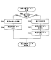
- FIG. 8A shows that when the user measures blood pressure in the nighttime blood pressure measurement mode with the sphygmomanometer 100, the user temporarily gets up and turns on the operation switch once, and after a predetermined time has elapsed from the time when the operation switch is turned on once. , The operation flow of the blood pressure measurement at the time of returning to the nocturnal blood pressure measurement mode is shown.
- the night measurement switch 52B is pressed at 11:30 pm to shift to the night blood pressure measurement mode, for example, the night measurement switch 52B is pressed while measuring at the scheduled time of 2:00 am. It is assumed that a schedule for measurement is set at 3:30 am, four hours after the set time.
- step S81 of FIG. 8A when the user presses down the nighttime measurement switch 52B provided on the main body 10, the sphygmomanometer 100 shifts from the normal blood pressure measurement mode to the nighttime blood pressure measurement mode. At this time, the indicator lamp 54 is turned on in the sphygmomanometer 100.
- step S82 of FIG. 8A the CPU 110 determines whether or not the user has pressed down the measurement interruption switch 52C provided on the main body 10.
- the sphygmomanometer 100 shifts to the measurement interruption switch process (step S83). In this example, it is assumed that the user presses down the measurement interruption switch 52C at 1:57 am.
- the CPU 110 determines whether or not the measurement is interrupted. If the sphygmomanometer 100 is not in the measurement interruption state (No in step S91), the CPU 110 acts as an interruption processing unit to set the measurement interruption state (step S92). At this time, the indicator lamp 54 is turned off. Subsequently, the CPU 110 initializes the measurement interruption timer (step S93). Subsequently, the CPU 110 turns on the measurement interruption timer (step S94). After that, the measurement interruption switch process is terminated, and the process returns to step S84 of FIG. 8A.
- step S84 of FIG. 8A the CPU 110 determines whether or not the measurement interruption timer of the sphygmomanometer 100 is turned on.
- the process proceeds to the measurement interruption timer processing (step S85).
- the CPU 110 acts as a return processing unit to increase the count of the measurement interruption timer. Subsequently, the CPU 110 determines whether or not a predetermined time Tb has elapsed after the measurement is interrupted (step S102). If the predetermined time Tb has not elapsed after the measurement is interrupted (NO in step S102), the measurement interruption timer process is terminated and the process returns to step S86 in FIG. 8A.
- the predetermined time Tb is set to 5 minutes, assuming the time required to get up from the bed, finish the work in the toilet, and return to the bed from the time when the measurement interruption switch 52C is pressed down by the user, for example. Will be done. However, it is not limited to this.
- the CPU 110 determines whether or not the measurement time is according to the schedule of the nighttime blood pressure measurement mode. When the measurement time is in accordance with the schedule (Yes in step S86), the CPU 110 subsequently determines whether or not the measurement interruption state is set. When the measurement interruption state is set (Yes in step S87), the sphygmomanometer 100 cancels the blood pressure measurement process (step S88). In this example, as shown in FIG. 8D, the 2:00 am measurement is cancelled.
- step S89 of FIG. 8A the CPU 110 determines whether or not the predetermined measurement determined by the schedule of the nighttime blood pressure measurement mode has been completed. If the predetermined measurement is not completed (incomplete in step S89), the process returns to step S82.
- the CPU 110 determines whether or not the user has pressed down the measurement interruption switch 52C provided on the main body 10 during standby. It is not necessary to press the measurement interruption switch 52C even when the user has finished using it. Unless the measurement interruption switch 52C is pressed down (No in step S82), the CPU 110 subsequently determines whether or not the measurement interruption timer of the sphygmomanometer 100 is turned on. When the measurement interruption timer is turned on (Yes in step S84), the process proceeds to the measurement interruption timer processing (step S85).
- the CPU 110 acts as a return processing unit to increase the count of the measurement interruption timer. Subsequently, the CPU 110 determines whether or not a predetermined time Tb has elapsed after the measurement is interrupted (step S102). When the measurement interruption return predetermined time Tb has elapsed (Yes in step S102), the CPU 110 acts as a return processing unit to reset the measurement interruption state (step S103). At this time, the indicator lamp 54 is turned on. Subsequently, the CPU 110 turns off the measurement interruption timer (step S104). After that, the measurement interruption timer process is terminated, and the process returns to step S86 of FIG. 8A.
- step S91 of FIG. 8B the CPU 110 interrupts the measurement. Determine if it is in a state.
- the CPU 110 acts as a return processing unit to reset the measurement interrupted state (step S95).
- the indicator lamp 54 is turned on.
- the CPU 110 turns off the measurement interruption timer (step S96). After that, the measurement interruption switch process is terminated, and the process returns to step S84 of FIG. 8A.
- step S86 of FIG. 8A the CPU 110 determines whether or not the measurement time is according to the schedule of the nighttime blood pressure measurement mode.
- the CPU 110 subsequently determines whether or not the measurement interruption state is set.
- the measurement interruption state is reset (No in step S86)
- the sphygmomanometer 100 proceeds to the blood pressure measurement process (step S88).
- FIG. 8D measurements are made on a schedule of 3:30 am.
- step S88 of FIG. 8A The blood pressure measurement process shown in step S88 of FIG. 8A is performed in the same manner as the operation flow shown in FIG. 6C, in steps S2 to S11 of FIG. 5 described above, except for steps S5 and S6. Subsequently, as shown in step S89 of FIG. 8A, the CPU 110 determines whether or not the measurement determined by the schedule of the nocturnal blood pressure measurement mode has been completed. When all the predetermined measurements are completed (finished in step S89), the nighttime blood pressure measurement mode of the sphygmomanometer 100 is terminated. At this time, the indicator lamp 54 is turned off.
- the indicator lamp 54 is turned on while in the nighttime blood pressure measurement mode, and is temporarily turned off or blinked only while the measurement is interrupted. Therefore, the user (subject) can confirm whether the sphygmomanometer 100 is in the nighttime blood pressure measurement mode or the measurement interrupted state by looking at the indicator lamp 54.
- the schedule of the nighttime blood pressure measurement mode is such that the nighttime measurement switch 52B is pressed at 11:30 pm to shift to the nighttime blood pressure measurement mode, for example, the measurement is performed at the scheduled time of 2:00 am, and the nighttime measurement switch is used. It is assumed that a schedule for measurement is set at 3:30 am, four hours after the time when 52B is pressed. However, the schedule is not limited to this, and a schedule for measuring all on time, such as 7:00 am, 1:00 am, 2:00 pm, and 3:00 am, is set after the night measurement switch 52B is pressed. May be good. Alternatively, a schedule may be set for all measurements with relative time settings, such as from the time when the night measurement switch 52B is pressed until 7:00 am, 2 hours later, 3 hours later, and 4 hours later.
- the sphygmomanometer 100 is a type that presses the wrist as the measurement site (the left wrist 90 is used in the above example, but the right wrist may be used), the blood pressure monitor 100 is compared with the type that presses the upper arm. It is expected that the degree of disturbing the sleep of the user (subject) is small (Imai et al., “Development and evaluation of a home nocturnal blood pressure monitoring system using a wrist-cuff device”, Blood Pressure Monitoring 2018, 23, P318. -326). Therefore, this sphygmomanometer 100 is suitable for nighttime blood pressure measurement.
- this sphygmomanometer 100 is integrally and compactly configured as a wrist-type sphygmomanometer, it is convenient for the user to handle.
- the sphygmomanometer 100 includes a measurement switch 52A, a nighttime measurement switch 52B, and a measurement interruption switch 52C provided on the main body 10 as an operation unit 52, but the present invention is not limited thereto.
- the operation unit 52 may be configured by, for example, a communication unit that receives an instruction from a smartphone or the like existing outside the sphygmomanometer 100 via wireless communication.
- the main body 10 is provided integrally with the cuff 20, but the present invention is not limited to this.
- the main body 10 may be configured as a separate body from the cuff 20 and may be connected to the cuff 20 (fluid bag 22) so that fluid can flow through a flexible air tube.
- the above-mentioned blood pressure measurement method is recorded as software (computer program) on a recording medium such as a CD (compact disc), a DVD (digital versatile disc), or a flash memory that can store data non-transitory. You may.
- a substantial computer device such as a personal computer, a PDA (Personal Digital Assistance), or a smartphone, the above-mentioned blood pressure measurement method can be applied to those computer devices. Can be executed.
Landscapes
- Health & Medical Sciences (AREA)
- Life Sciences & Earth Sciences (AREA)
- Engineering & Computer Science (AREA)
- Physics & Mathematics (AREA)
- Cardiology (AREA)
- Vascular Medicine (AREA)
- Biophysics (AREA)
- Veterinary Medicine (AREA)
- Public Health (AREA)
- General Health & Medical Sciences (AREA)
- Animal Behavior & Ethology (AREA)
- Surgery (AREA)
- Molecular Biology (AREA)
- Pathology (AREA)
- Biomedical Technology (AREA)
- Heart & Thoracic Surgery (AREA)
- Medical Informatics (AREA)
- Physiology (AREA)
- Artificial Intelligence (AREA)
- Ophthalmology & Optometry (AREA)
- Fuzzy Systems (AREA)
- Mathematical Physics (AREA)
- Signal Processing (AREA)
- Psychiatry (AREA)
- Computer Vision & Pattern Recognition (AREA)
- Evolutionary Computation (AREA)
- Measuring Pulse, Heart Rate, Blood Pressure Or Blood Flow (AREA)
Priority Applications (3)
| Application Number | Priority Date | Filing Date | Title |
|---|---|---|---|
| CN202080073792.9A CN114599275B (zh) | 2019-10-24 | 2020-10-05 | 血压计、血压测量方法及存储介质 |
| DE112020005142.0T DE112020005142T5 (de) | 2019-10-24 | 2020-10-05 | Blutdruckmessgerät, blutdruckmessverfahren und programm |
| US17/722,876 US20220233083A1 (en) | 2019-10-24 | 2022-04-18 | Sphygmomanometer, blood pressure measurement method, and computer-readable recording medium |
Applications Claiming Priority (2)
| Application Number | Priority Date | Filing Date | Title |
|---|---|---|---|
| JP2019-193674 | 2019-10-24 | ||
| JP2019193674A JP7400342B2 (ja) | 2019-10-24 | 2019-10-24 | 血圧計、血圧測定方法、及びプログラム |
Related Child Applications (1)
| Application Number | Title | Priority Date | Filing Date |
|---|---|---|---|
| US17/722,876 Continuation US20220233083A1 (en) | 2019-10-24 | 2022-04-18 | Sphygmomanometer, blood pressure measurement method, and computer-readable recording medium |
Publications (1)
| Publication Number | Publication Date |
|---|---|
| WO2021079729A1 true WO2021079729A1 (ja) | 2021-04-29 |
Family
ID=75620003
Family Applications (1)
| Application Number | Title | Priority Date | Filing Date |
|---|---|---|---|
| PCT/JP2020/037769 Ceased WO2021079729A1 (ja) | 2019-10-24 | 2020-10-05 | 血圧計、血圧測定方法、及びプログラム |
Country Status (5)
| Country | Link |
|---|---|
| US (1) | US20220233083A1 (enExample) |
| JP (1) | JP7400342B2 (enExample) |
| CN (1) | CN114599275B (enExample) |
| DE (1) | DE112020005142T5 (enExample) |
| WO (1) | WO2021079729A1 (enExample) |
Cited By (1)
| Publication number | Priority date | Publication date | Assignee | Title |
|---|---|---|---|---|
| EP4431012A4 (en) * | 2021-12-21 | 2024-09-25 | Huawei Technologies Co., Ltd. | Blood pressure measurement method, and electronic device and medium thereof |
Families Citing this family (3)
| Publication number | Priority date | Publication date | Assignee | Title |
|---|---|---|---|---|
| JP7716167B1 (ja) * | 2025-03-11 | 2025-07-31 | 株式会社エー・アンド・デイ | 血圧計およびその通信制御方法 |
| JP7717994B1 (ja) * | 2025-03-11 | 2025-08-04 | 株式会社エー・アンド・デイ | 血圧計および血圧測定方法 |
| JP7748591B1 (ja) * | 2025-03-11 | 2025-10-02 | 株式会社エー・アンド・デイ | 血圧計 |
Citations (3)
| Publication number | Priority date | Publication date | Assignee | Title |
|---|---|---|---|---|
| JPH04279147A (ja) * | 1991-03-07 | 1992-10-05 | Terumo Corp | 自動血圧計 |
| WO2012018029A1 (ja) * | 2010-08-06 | 2012-02-09 | 株式会社オムシー | 血圧測定装置 |
| JP2013510642A (ja) * | 2009-11-11 | 2013-03-28 | カズ ヨーロッパ エスエー | 動脈血圧計用のカフ |
Family Cites Families (19)
| Publication number | Priority date | Publication date | Assignee | Title |
|---|---|---|---|---|
| JPS548142B2 (enExample) | 1974-05-18 | 1979-04-12 | ||
| US5319355A (en) * | 1991-03-06 | 1994-06-07 | Russek Linda G | Alarm for patient monitor and life support equipment system |
| US5560366A (en) * | 1993-11-29 | 1996-10-01 | Colin Corporation | Oscillometric blood pressure measuring apparatus |
| JP3067904U (ja) | 1999-10-04 | 2000-04-21 | 佐野丸興株式会社 | 録音装置付血圧計 |
| US6902531B2 (en) * | 2003-05-01 | 2005-06-07 | Ge Medical Systems Information Technologies, Inc. | Pneumatic control of blood pressure determinations |
| ES2353526T3 (es) * | 2005-06-14 | 2011-03-02 | Microlife Intellectual Property Gmbh | Un dispositivo para medir la presión sanguínea y un método para operar un dispositivo para medir la presión sanguínea. |
| JP2007044439A (ja) * | 2005-08-12 | 2007-02-22 | Omron Healthcare Co Ltd | 電子血圧計 |
| US20090326391A1 (en) | 2008-01-04 | 2009-12-31 | Aviton Care Limited | Wrist-type blood pressure meter |
| JP4978483B2 (ja) * | 2008-01-23 | 2012-07-18 | オムロンヘルスケア株式会社 | 血圧測定装置および血圧測定データの処理方法 |
| JP2010099383A (ja) * | 2008-10-27 | 2010-05-06 | Omron Healthcare Co Ltd | 電子血圧計 |
| US9117015B2 (en) * | 2008-12-23 | 2015-08-25 | Roche Diagnostics Operations, Inc. | Management method and system for implementation, execution, data collection, and data analysis of a structured collection procedure which runs on a collection device |
| KR101577342B1 (ko) * | 2009-05-07 | 2015-12-15 | 삼성전자주식회사 | 혈압 측정 장치 및 방법 |
| JP2011101735A (ja) * | 2009-11-11 | 2011-05-26 | Omron Healthcare Co Ltd | 電子血圧計 |
| JP5714469B2 (ja) * | 2011-11-15 | 2015-05-07 | シチズンホールディングス株式会社 | 電子血圧計 |
| JP5613922B2 (ja) * | 2012-02-23 | 2014-10-29 | 株式会社タニタ | 血圧測定装置および血圧測定方法 |
| AU2015312215B2 (en) | 2014-09-02 | 2017-10-19 | Apple Inc. | Physical activity and workout monitor |
| US20170293727A1 (en) * | 2016-04-08 | 2017-10-12 | Apple Inc. | Intelligent blood pressure monitoring |
| DE112018001373T5 (de) | 2017-03-15 | 2019-11-28 | Omron Corporation | Blutdruckmessgerät und blutdruckmessverfahren |
| US12478272B2 (en) * | 2020-12-23 | 2025-11-25 | Masimo Corporation | Patient monitoring systems, devices, and methods |
-
2019
- 2019-10-24 JP JP2019193674A patent/JP7400342B2/ja active Active
-
2020
- 2020-10-05 WO PCT/JP2020/037769 patent/WO2021079729A1/ja not_active Ceased
- 2020-10-05 DE DE112020005142.0T patent/DE112020005142T5/de active Pending
- 2020-10-05 CN CN202080073792.9A patent/CN114599275B/zh active Active
-
2022
- 2022-04-18 US US17/722,876 patent/US20220233083A1/en active Pending
Patent Citations (3)
| Publication number | Priority date | Publication date | Assignee | Title |
|---|---|---|---|---|
| JPH04279147A (ja) * | 1991-03-07 | 1992-10-05 | Terumo Corp | 自動血圧計 |
| JP2013510642A (ja) * | 2009-11-11 | 2013-03-28 | カズ ヨーロッパ エスエー | 動脈血圧計用のカフ |
| WO2012018029A1 (ja) * | 2010-08-06 | 2012-02-09 | 株式会社オムシー | 血圧測定装置 |
Cited By (1)
| Publication number | Priority date | Publication date | Assignee | Title |
|---|---|---|---|---|
| EP4431012A4 (en) * | 2021-12-21 | 2024-09-25 | Huawei Technologies Co., Ltd. | Blood pressure measurement method, and electronic device and medium thereof |
Also Published As
| Publication number | Publication date |
|---|---|
| CN114599275B (zh) | 2025-02-11 |
| JP7400342B2 (ja) | 2023-12-19 |
| US20220233083A1 (en) | 2022-07-28 |
| DE112020005142T5 (de) | 2022-07-14 |
| JP2021065462A (ja) | 2021-04-30 |
| CN114599275A (zh) | 2022-06-07 |
Similar Documents
| Publication | Publication Date | Title |
|---|---|---|
| CN114786571B (zh) | 血压计 | |
| WO2021079729A1 (ja) | 血圧計、血圧測定方法、及びプログラム | |
| JP6786706B2 (ja) | 血圧測定装置、血圧測定方法及びプログラム | |
| JP2010131305A (ja) | 電子血圧計 | |
| US20220240795A1 (en) | Sphygmomanometer, blood pressure measurement method, and computer-readable recording medium | |
| WO2021095813A1 (ja) | 血圧計、血圧測定方法、およびプログラム | |
| JP2021078552A5 (enExample) | ||
| US12303241B2 (en) | Sphygmomanometer, blood pressure calculation method, and computer-readable recording medium | |
| US20230143560A1 (en) | Sphygmomanometer, blood pressure measurement method, and computer-readable recording medium | |
| JP7354792B2 (ja) | 血圧計、血圧測定方法、及びプログラム | |
| WO2021090811A1 (ja) | 血圧計、血圧算出方法、およびプログラム | |
| JP7476512B2 (ja) | 血圧計、血圧計の作動方法、およびプログラム | |
| WO2021039301A1 (ja) | 血圧計、血圧算出方法、およびプログラム | |
| JP7354791B2 (ja) | 血圧測定システム | |
| JP2021074088A5 (enExample) | ||
| WO2021085043A1 (ja) | 血圧計、血圧測定方法、およびプログラム | |
| JP2021069445A5 (enExample) | ||
| JP2016198376A (ja) | 血圧計 |
Legal Events
| Date | Code | Title | Description |
|---|---|---|---|
| 121 | Ep: the epo has been informed by wipo that ep was designated in this application |
Ref document number: 20878041 Country of ref document: EP Kind code of ref document: A1 |
|
| 122 | Ep: pct application non-entry in european phase |
Ref document number: 20878041 Country of ref document: EP Kind code of ref document: A1 |
|
| WWG | Wipo information: grant in national office |
Ref document number: 202080073792.9 Country of ref document: CN |