WO2021079729A1 - 血圧計、血圧測定方法、及びプログラム - Google Patents
血圧計、血圧測定方法、及びプログラム Download PDFInfo
- Publication number
- WO2021079729A1 WO2021079729A1 PCT/JP2020/037769 JP2020037769W WO2021079729A1 WO 2021079729 A1 WO2021079729 A1 WO 2021079729A1 JP 2020037769 W JP2020037769 W JP 2020037769W WO 2021079729 A1 WO2021079729 A1 WO 2021079729A1
- Authority
- WO
- WIPO (PCT)
- Prior art keywords
- blood pressure
- pressure measurement
- measurement
- sphygmomanometer
- nighttime
- Prior art date
Links
Images


Classifications
-
- A—HUMAN NECESSITIES
- A61—MEDICAL OR VETERINARY SCIENCE; HYGIENE
- A61B—DIAGNOSIS; SURGERY; IDENTIFICATION
- A61B5/00—Measuring for diagnostic purposes; Identification of persons
- A61B5/02—Detecting, measuring or recording pulse, heart rate, blood pressure or blood flow; Combined pulse/heart-rate/blood pressure determination; Evaluating a cardiovascular condition not otherwise provided for, e.g. using combinations of techniques provided for in this group with electrocardiography or electroauscultation; Heart catheters for measuring blood pressure
- A61B5/021—Measuring pressure in heart or blood vessels
- A61B5/022—Measuring pressure in heart or blood vessels by applying pressure to close blood vessels, e.g. against the skin; Ophthalmodynamometers
- A61B5/0225—Measuring pressure in heart or blood vessels by applying pressure to close blood vessels, e.g. against the skin; Ophthalmodynamometers the pressure being controlled by electric signals, e.g. derived from Korotkoff sounds
-
- A—HUMAN NECESSITIES
- A61—MEDICAL OR VETERINARY SCIENCE; HYGIENE
- A61B—DIAGNOSIS; SURGERY; IDENTIFICATION
- A61B5/00—Measuring for diagnostic purposes; Identification of persons
- A61B5/02—Detecting, measuring or recording pulse, heart rate, blood pressure or blood flow; Combined pulse/heart-rate/blood pressure determination; Evaluating a cardiovascular condition not otherwise provided for, e.g. using combinations of techniques provided for in this group with electrocardiography or electroauscultation; Heart catheters for measuring blood pressure
- A61B5/021—Measuring pressure in heart or blood vessels
- A61B5/022—Measuring pressure in heart or blood vessels by applying pressure to close blood vessels, e.g. against the skin; Ophthalmodynamometers
- A61B5/0235—Valves specially adapted therefor
-
- A—HUMAN NECESSITIES
- A61—MEDICAL OR VETERINARY SCIENCE; HYGIENE
- A61B—DIAGNOSIS; SURGERY; IDENTIFICATION
- A61B5/00—Measuring for diagnostic purposes; Identification of persons
- A61B5/68—Arrangements of detecting, measuring or recording means, e.g. sensors, in relation to patient
- A61B5/6801—Arrangements of detecting, measuring or recording means, e.g. sensors, in relation to patient specially adapted to be attached to or worn on the body surface
- A61B5/6813—Specially adapted to be attached to a specific body part
- A61B5/6824—Arm or wrist
-
- A—HUMAN NECESSITIES
- A61—MEDICAL OR VETERINARY SCIENCE; HYGIENE
- A61B—DIAGNOSIS; SURGERY; IDENTIFICATION
- A61B5/00—Measuring for diagnostic purposes; Identification of persons
- A61B5/72—Signal processing specially adapted for physiological signals or for diagnostic purposes
- A61B5/7235—Details of waveform analysis
- A61B5/7264—Classification of physiological signals or data, e.g. using neural networks, statistical classifiers, expert systems or fuzzy systems
- A61B5/7267—Classification of physiological signals or data, e.g. using neural networks, statistical classifiers, expert systems or fuzzy systems involving training the classification device
-
- A—HUMAN NECESSITIES
- A61—MEDICAL OR VETERINARY SCIENCE; HYGIENE
- A61B—DIAGNOSIS; SURGERY; IDENTIFICATION
- A61B2560/00—Constructional details of operational features of apparatus; Accessories for medical measuring apparatus
- A61B2560/02—Operational features
- A61B2560/029—Operational features adapted for auto-initiation
-
- A—HUMAN NECESSITIES
- A61—MEDICAL OR VETERINARY SCIENCE; HYGIENE
- A61B—DIAGNOSIS; SURGERY; IDENTIFICATION
- A61B2560/00—Constructional details of operational features of apparatus; Accessories for medical measuring apparatus
- A61B2560/04—Constructional details of apparatus
- A61B2560/0475—Special features of memory means, e.g. removable memory cards
-
- A—HUMAN NECESSITIES
- A61—MEDICAL OR VETERINARY SCIENCE; HYGIENE
- A61B—DIAGNOSIS; SURGERY; IDENTIFICATION
- A61B5/00—Measuring for diagnostic purposes; Identification of persons
- A61B5/02—Detecting, measuring or recording pulse, heart rate, blood pressure or blood flow; Combined pulse/heart-rate/blood pressure determination; Evaluating a cardiovascular condition not otherwise provided for, e.g. using combinations of techniques provided for in this group with electrocardiography or electroauscultation; Heart catheters for measuring blood pressure
- A61B5/021—Measuring pressure in heart or blood vessels
- A61B5/022—Measuring pressure in heart or blood vessels by applying pressure to close blood vessels, e.g. against the skin; Ophthalmodynamometers
Definitions
- the present invention relates to a sphygmomanometer, and more particularly to a sphygmomanometer having a nighttime (sleeping) blood pressure measurement mode.
- the present invention also relates to a blood pressure measuring method for measuring blood pressure by such a sphygmomanometer.
- the present invention also relates to a program for causing a computer to execute such a blood pressure measuring method.
- a blood pressure measurement period is specified in a nighttime (sleeping) blood pressure measurement mode, and a measurement start time (or start time) is specified.
- a measurement start time or start time
- the measurement end time or end time
- the time is set at an arbitrary time interval (for example, 1 hour) to measure and record the blood pressure.
- the subject may temporarily get up to go to the bathroom.
- blood pressure measurement predetermined by a schedule built-in timer
- blood pressure measurement may not be performed correctly in the nighttime blood pressure measurement mode.
- an object of the present invention is to provide a sphygmomanometer and a blood pressure measurement method capable of preventing a predetermined blood pressure measurement from being started while the subject is temporarily awake in the nocturnal blood pressure measurement mode. There is. Another object of the present invention is to provide a program for causing a computer to execute such a blood pressure measuring method.
- the sphygmomanometer of this disclosure is A sphygmomanometer that measures blood pressure by temporarily pressing the subject's area to be measured with a blood pressure measurement cuff. It has a nighttime blood pressure measurement mode that automatically starts blood pressure measurement according to a predetermined schedule. In the nighttime blood pressure measurement mode, the blood pressure measurement is automatically started according to the schedule, and when the blood pressure measurement cuff is in the pressurizing process or the depressurizing process, the blood pressure measuring unit and the blood pressure measuring unit are used.
- An operation switch for inputting an instruction to interrupt the nighttime blood pressure measurement mode or return to the nighttime blood pressure measurement mode, and In the nighttime blood pressure measurement mode, when the operation switch is operated once, an interruption processing unit that performs a process of shifting to a measurement interruption state in which blood pressure measurement is not started even when the time specified in the schedule arrives, and an interruption processing unit.
- the "predetermined time” is set to, for example, 5 minutes assuming the time required for the subject to get up from the bed, finish the work in the toilet, and return to the bed again. However, it is not limited to this.
- the sphygmomanometer of this disclosure automatically starts blood pressure measurement according to the above schedule in the above nighttime blood pressure measurement mode.
- the blood pressure measuring unit measures the blood pressure when the blood pressure measuring cuff is in the pressurizing process or the depressurizing process.
- An instruction to interrupt the nighttime blood pressure measurement mode or return to the nighttime blood pressure measurement mode is input to the operation switch.
- the interruption processing unit performs a process of shifting to a measurement interruption state in which blood pressure measurement is not started even when the time specified in the schedule arrives.
- the return processing unit measures the nighttime blood pressure on the condition that the operation switch is operated again in the measurement interrupted state, or after a predetermined time has elapsed from the time when the operation switch is operated once. Performs the process of returning to the mode. Therefore, according to this sphygmomanometer, it is possible to prevent the predetermined blood pressure measurement from being started while the subject is temporarily awake in the nocturnal blood pressure measurement mode.
- the return processing unit performs a process of returning to the nighttime blood pressure measurement mode as soon as the operation switch is operated again, on condition that the operation switch is operated again. It is characterized by doing.
- the operation switch when the return processing unit is subject to the operation of the operation switch again, the operation switch is operated again at night after a predetermined time has elapsed from the time when the operation switch is operated again. It is characterized by performing a process of returning to the blood pressure measurement mode.
- the "predetermined time” is set to, for example, 5 minutes assuming the time required for the subject to enter a resting state after pressing the operation switch again. However, it is not limited to this.
- a process of returning to the nighttime blood pressure measurement mode is performed after a predetermined time has elapsed from the time when the operation switch is operated again. Therefore, it is possible to continue the nighttime blood pressure measurement mode after waiting for the subject to be in a resting state.
- the sphygmomanometer of one embodiment is characterized by including an indicator lamp indicating whether the sphygmomanometer is in the nocturnal blood pressure measurement mode or in the measurement interruption state.
- the subject can confirm whether the blood pressure monitor is in the nighttime blood pressure measurement mode or in the measurement interruption state by looking at the indicator lamp.
- the sphygmomanometer of one embodiment is characterized in that the site to be measured is the wrist.
- the blood pressure monitor of this embodiment is a type that presses the wrist as the measurement site, it is expected that the degree of disturbing the sleep of the subject is less than that of the type that presses the upper arm (Imai et al). ., “Development and evaluation of a home nocturnal blood pressure monitoring system using a wrist-cuff device”, Blood Pressure Monitoring 2018, 23, P318-326). Therefore, this sphygmomanometer is suitable for nighttime (sleeping) blood pressure measurement.
- the sphygmomanometer of one embodiment includes a main body provided integrally with the blood pressure measuring cuff.
- the main body is characterized by incorporating the blood pressure measuring unit, the operation switch, the interrupt processing unit, and the return processing unit.
- the "blood pressure measuring unit” drives and controls, for example, a pump that supplies a pressurizing fluid to the blood pressure measuring cuff, a valve that exhausts the fluid from the blood pressure measuring cuff, and these pumps / valves. Includes elements.
- the sphygmomanometer of this embodiment can be integrally and compactly configured. Therefore, the handling by the user becomes convenient.
- the blood pressure measurement method of this disclosure is It is a blood pressure measurement method for a sphygmomanometer that measures blood pressure by temporarily pressing the area to be measured by a blood pressure measurement cuff.
- the above blood pressure monitor It has a nighttime blood pressure measurement mode that automatically starts blood pressure measurement according to a predetermined schedule, and also has a nighttime blood pressure measurement mode. It is equipped with an operation switch for inputting an instruction to interrupt the nighttime blood pressure measurement mode or return to the nighttime blood pressure measurement mode.
- the above blood pressure measurement method is In the nighttime blood pressure measurement mode, the blood pressure measurement is automatically started according to the schedule, and the blood pressure is measured when the blood pressure measurement cuff is in the pressurization process or the depressurization process.
- a process of shifting to a measurement interrupted state in which blood pressure measurement is not started even when the time specified in the schedule arrives is performed.
- the blood pressure measurement method disclosed in this disclosure it is possible to prevent the start of a predetermined blood pressure measurement while the subject is temporarily awake in the nighttime blood pressure measurement mode.
- this disclosed program is a program for causing a computer to execute the above blood pressure measurement method.
- the above blood pressure measurement method can be carried out by causing a computer to execute the program of this disclosure.
- a predetermined blood pressure measurement is started while the subject is temporarily awake. Can be prevented.
- the program of this disclosure also allows a computer to perform such a blood pressure measurement method.
- FIG. 6 is a diagram showing the relationship between the operation timing of the nighttime measurement switch and the measurement interruption switch and the measurement schedule of the nighttime blood pressure measurement mode in the blood pressure measurement of FIG. 6A with the passage of time.
- FIG. 7A It is a figure which shows the measurement result which performed the blood pressure measurement by the said sphygmomanometer.
- FIG. 6 is a diagram showing the relationship between the operation timing of the nighttime measurement switch and the measurement interruption switch and the measurement schedule of the nighttime blood pressure measurement mode in the blood pressure measurement of FIG. 7A with the passage of time.
- the subject When measuring blood pressure in the nighttime blood pressure measurement mode with the above blood pressure monitor, the subject temporarily gets up and operates the measurement interruption switch once, and after a predetermined time has elapsed from the time of the one operation, the nighttime blood pressure It is a figure which shows the operation flow of the blood pressure measurement at the time of returning to the measurement mode. It is a figure which shows the operation flow of the measurement interruption switch processing in the operation flow of the blood pressure measurement of FIG. 8A.
- FIG. 5 is a diagram showing the relationship between the operation timing of the nighttime measurement switch and the measurement interruption switch and the measurement schedule of the nighttime blood pressure measurement mode in the blood pressure measurement of FIG. 8A with the passage of time.
- FIG. 1 shows the appearance of the wrist type sphygmomanometer 100 according to the embodiment of the present invention.
- the sphygmomanometer 100 is roughly divided into a blood pressure measuring cuff 20 to be attached to the left wrist 90 (see FIG. 3 described later) as a measurement site, and a main body 10 integrally attached to the cuff 20. ing.
- the cuff 20 is a general one for a wrist-type sphygmomanometer, and has an elongated band-like shape so as to surround the left wrist 90 along the circumferential direction.
- the cuff 20 contains a fluid bag 22 (see FIG. 2) for pressing the left wrist 90.
- a carla having appropriate flexibility may be provided in the cuff 20.
- the main body 10 is integrally attached to a portion substantially in the center of the strip-shaped cuff 20 in the longitudinal direction.
- the portion to which the main body 10 is attached is planned to correspond to the palm side surface (palm side surface) 90a of the left wrist 90 in the mounted state.
- the main body 10 has a flat, substantially rectangular parallelepiped shape along the outer peripheral surface of the cuff 20.
- the main body 10 is formed to be small and thin so as not to interfere with the sleep of the user (in this example, the subject; the same applies hereinafter). Further, the corners of the main body 10 are rounded (the corners are rounded).
- a display 50 forming a display screen and an operation unit 52 for inputting an instruction from the user are input. And are provided.
- the display 50 is composed of an LCD (Liquid Crystal Display) and displays predetermined information according to a control signal from a CPU (Central Processing Unit) 110 described later.
- the systolic blood pressure (unit: mmHg), the diastolic blood pressure (unit: mmHg), and the pulse (unit: beat / minute) are displayed.
- the display 50 may consist of an organic EL (ElectroLuminescence) display or may include an LED (Light Emitting Diode).
- the operation unit 52 inputs an operation signal according to an instruction by the user to the CPU 110 described later.
- the operation unit 52 includes a measurement switch 52A for receiving a blood pressure measurement instruction by the user and a night measurement switch 52B for receiving an instruction to switch the mode between the normal blood pressure measurement mode and the nighttime blood pressure measurement mode.
- a measurement interruption switch 52C as an operation switch for inputting an instruction to interrupt the nighttime blood pressure measurement mode or return to the nighttime blood pressure measurement mode, and a check switch 52D for displaying the stored measurement result on the display unit 50.
- the "normal blood pressure measurement mode” means a mode in which, when a blood pressure measurement instruction is input by the measurement switch 52A, the blood pressure is measured in response to the blood pressure measurement instruction.
- the "nighttime blood pressure measurement mode” means a mode in which blood pressure measurement is automatically started according to a predetermined schedule so that the user can measure the blood pressure value during sleep.
- the predetermined schedule refers to a plan for measuring at a fixed time such as 1:00, 2:00, or 3:00 at midnight, or a plan for measuring once every two hours after the night measurement switch 52B is pressed.
- the measurement switch 52A, the nighttime measurement switch 52B, and the measurement interruption switch 52C are all momentary type (self-recovery type) switches, and are turned on and released only while being pressed down. When it is, it returns to the off state.
- the measurement switch 52A When the measurement switch 52A is pressed down while the sphygmomanometer 100 is in the normal blood pressure measurement mode, it means a blood pressure measurement instruction, and the cuff 20 temporarily presses the area to be measured (left wrist 90). Blood pressure measurements are performed by the metric method.
- the measurement switch 52A When the measurement switch 52A is pressed down again during blood pressure measurement (for example, while pressurizing the cuff 20), it means an instruction to stop blood pressure measurement, and blood pressure measurement is stopped immediately.
- the night measurement switch 52B is pressed down while the sphygmomanometer 100 is in the normal blood pressure measurement mode, it means an instruction to shift to the night blood pressure measurement mode, and the sphygmomanometer 100 measures the night blood pressure from the normal blood pressure measurement mode. Move to mode. In the nocturnal blood pressure measurement mode, as described above, blood pressure measurement by the oscillometric method is automatically started according to a predetermined schedule. If the night measurement switch 52B is pressed again while the sphygmomanometer 100 is in the nighttime blood pressure measurement mode, it means an instruction to stop the nighttime blood pressure measurement mode, and the sphygmomanometer 100 shifts from the nighttime blood pressure measurement mode to the normal blood pressure measurement mode. To do.
- the indicator lamp 54 is provided integrally with the night measurement switch 52B.
- the indicator lamp 54 is turned off while the sphygmomanometer 100 is in the normal blood pressure measurement mode.
- the indicator lamp 54 is turned on while the sphygmomanometer 100 is in the nighttime blood pressure measurement mode, and is temporarily turned off only while the measurement is interrupted, which will be described later.
- the subject can confirm whether the blood pressure monitor 100 is in the nighttime blood pressure measurement mode or the measurement interrupted state by looking at the indicator lamp 54.
- the user may instruct blood pressure measurement by interruption by pressing the measurement switch 52A, in addition to the predetermined schedule.
- the blood pressure measurement is temporarily performed by the cuff 20 in response to the interrupted blood pressure measurement instruction, and the blood pressure measurement is performed by the oscillometric method.
- FIG. 2 shows the block configuration of the sphygmomanometer 100.
- the cuff 20 includes a fluid bag 22 for pressing the left wrist 90 as a measurement site as described above.
- the fluid bag 22 and the main body 10 are connected by an air pipe 39 so that the fluid can flow.
- the main body 10 includes a CPU 110 as a control unit, a memory 51 as a storage unit, a power supply unit 53, a pressure sensor 31, a pump 32, and a valve 33. And is installed. Further, the main body 10 includes an A / D conversion circuit 310 that converts the output of the pressure sensor 31 from an analog signal to a digital signal, a pump drive circuit 320 that drives the pump 32, and a valve drive circuit 330 that drives the valve 33. It is installed.
- the pressure sensor 31, the pump 32, and the valve 33 are commonly connected to the fluid bag 22 through the air pipe 39 so that the fluid can flow.
- the memory 51 stores a program for controlling the sphygmomanometer 100, data used for controlling the sphygmomanometer 100, setting data for setting various functions of the sphygmomanometer 100, data of blood pressure value measurement results, and the like.
- the memory 51 is used as a work memory or the like when a program is executed.
- the memory 51 stores an algorithm for calculating blood pressure by the oscillometric method.
- the CPU 110 shown in FIG. 2 controls the operation of the entire sphygmomanometer 100. Specifically, the CPU 110 functions as a blood pressure measuring unit and drives the pump 32 and the valve 33 in response to an operation signal from the operation unit 52 according to a program for controlling the sphygmomanometer 100 stored in the memory 51. Control. Further, the CPU 110 functions as a blood pressure measuring unit to automatically start blood pressure measurement according to a schedule in the nighttime blood pressure measuring mode, and when the blood pressure measuring cuff is in the pressurizing process or the depressurizing process, the blood pressure is calculated by the oscillometric method. Blood pressure is measured using the algorithm for.
- the CPU 110 functions as an interruption processing unit, and when the measurement interruption switch 52C is turned on once, performs a process of shifting to a measurement interruption state in which blood pressure measurement is not started even when the time set in the schedule arrives. Further, the CPU 110 acts as a return processing unit, and on the condition that the measurement interruption switch 52C is turned on again in the measurement interruption state, or a predetermined time from the time when the measurement interruption switch 52C is turned on once. After the lapse of time, the process of returning to the nighttime blood pressure measurement mode is performed. These processes will be described in detail later.
- the power supply unit 53 includes a secondary battery, a CPU 110, a pressure sensor 31, a pump 32, a valve 33, a display 50, a memory 51, an A / D conversion circuit 310, a pump drive circuit 320, and a valve drive circuit 330. Power is supplied to each part of.
- the pump 32 supplies air as a fluid to the fluid bag 22 through the air pipe 39 in order to pressurize the pressure (cuff pressure) in the fluid bag 22 contained in the cuff 20.
- the valve 33 is opened and closed to discharge the air from the fluid bag 22 through the air pipe 39 or to fill the fluid bag 22 with air to control the cuff pressure.
- the pump drive circuit 320 drives the pump 32 based on a control signal given from the CPU 110.
- the valve drive circuit 330 opens and closes the valve 33 based on a control signal given from the CPU 110.
- the pressure sensor 31 and the A / D conversion circuit 310 function as a pressure detection unit that detects the pressure of the cuff.
- the pressure sensor 31 is a piezoresistive pressure sensor in this example, and outputs the pressure (cuff pressure) in the fluid bag 22 contained in the cuff 20 as an electric resistance due to the piezoresistive effect through the air pipe 39.
- the A / D conversion circuit 310 converts the output (electrical resistance) of the pressure sensor 31 from an analog signal to a digital signal and outputs it to the CPU 110.
- the A / D conversion circuit 310 works as an oscillation circuit that oscillates at a frequency corresponding to the electric resistance from the pressure sensor 31, and the CPU 110 acquires a signal representing the cuff pressure according to the oscillation frequency.
- FIG. 5 shows an operation flow when a user measures blood pressure with a sphygmomanometer 100 in a normal blood pressure measurement mode.
- the measurement switch 52A is continuously pressed for, for example, 3 seconds or more in the power-off state, the power is turned on and the normal blood pressure measurement mode is set by default.
- the “sitting position” means that a user 80 wearing a sphygmomanometer 100 on a left wrist 90 sits on a chair 97 or the like, puts his left elbow on a table 98, and puts his left wrist 90 on his trunk.
- by raising it diagonally forward (hands up, elbows down) it means a posture in which the left wrist 90 (and sphygmomanometer 100) is maintained at the height level of the heart 81.
- the "supine position” as shown in FIG. 4B, a user 80 wearing a sphygmomanometer 100 on the left wrist 90 is placed on a horizontal floor surface 99 or the like with the left elbow extended along the trunk. It means lying on his back.
- step S2 of FIG. 5 when the user presses down the measurement switch 52A provided on the main body 10 and inputs a blood pressure measurement instruction, the CPU 110 initializes the pressure sensor 31 (step S2). Specifically, the CPU 110 initializes the processing memory area, turns off (stops) the pump 32, and adjusts the pressure sensor 31 to 0 mmHg (atmospheric pressure is set to 0 mmHg) with the valve 33 open. )I do.
- the CPU 110 closes the valve 33 via the valve drive circuit 330 (step S3), and then turns on (starts) the pump 32 via the pump drive circuit 320 to form the cuff 20 (fluid bag 22). Pressurization is started (step S4). At this time, the CPU 110 controls the pressurizing speed of the cuff pressure PC, which is the pressure inside the fluid bag 22, based on the output of the pressure sensor 31 while supplying air from the pump 32 to the fluid bag 22 through the air pipe 39. ..
- step S5 of FIG. 5 the CPU 110 acts as a pressure measuring unit to determine whether or not the pressure has reached a predetermined level.
- the predetermined pressure is reached (Yes in step S5)
- the cuff 20 winding state is determined and displayed (step S6).
- the determination of the winding state can be performed by a known method as disclosed in, for example, Japanese Patent No. 5408142.
- the predetermined pressure is not reached (No in step S5), the pressurization of the cuff 20 is continued.
- step S7 of FIG. 5 the blood pressure calculation stored in the memory 51 is calculated based on the pulse wave signal (variable component due to the pulse wave included in the output of the pressure sensor 31) acquired at this time. Attempts to calculate blood pressure values (maximum blood pressure (systolic blood pressure) and diastolic blood pressure (diastolic blood pressure)).
- step S8 if the blood pressure value cannot be calculated yet due to lack of data (No in step S8), the cuff pressure PC reaches the upper limit pressure (for safety, for example, 300 mmHg is predetermined). Unless otherwise specified, the processes of steps S4 to S8 are repeated.
- step S8 When the blood pressure value can be calculated in this way (Yes in step S8), the CPU 110 turns off the pump 32 (step S9), opens the valve 33 (step S10), and enters the cuff 20 (fluid bag 22). Controls the exhaust of air.
- the CPU 110 displays the calculated blood pressure value on the display 50 (step S11), and controls to save the blood pressure value in the memory 51.
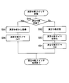
- FIG. 6A shows that when the user measures blood pressure in the nighttime blood pressure measurement mode with the sphygmomanometer 100, the user temporarily gets up to go to the toilet, for example, and turns on the measurement interruption switch 52C once, and then the measurement interruption switch 52C. The operation flow of blood pressure measurement when is turned on again is shown.
- FIG. 4B it is assumed that the user 80 wearing the sphygmomanometer 100 on the left wrist 90 is in the supine position.
- step S21 of FIG. 6A when the user presses down the nighttime measurement switch 52B provided on the main body 10, the sphygmomanometer 100 shifts from the normal blood pressure measurement mode to the nighttime blood pressure measurement mode. At this time, the sphygmomanometer 100 turns on the indicator lamp 54 (see FIG. 1). As a result, the user can confirm that the sphygmomanometer 100 is in the nighttime blood pressure measurement mode by looking at the indicator lamp 54.
- the night measurement switch 52B is pressed at 11:30 pm to shift to the night blood pressure measurement mode, for example, the measurement is performed at the scheduled time of 2:00 am and the night measurement switch 52B is pressed. It is assumed that a schedule for measurement is set at 3:30 am, four hours after the time set (Note that in FIG. 6D and FIGS. 7D and 8D described later, a 24-hour display such as 23:30 is displayed. doing.).
- the CPU 110 determines whether or not the user has pressed down the measurement interruption switch 52C provided on the main body 10.
- the CPU 110 acts as an interruption processing unit and shifts to the measurement interruption switch processing (step S23).
- the indicator lamp 54 is turned off in the sphygmomanometer 100.
- the user can confirm that the sphygmomanometer 100 is in the measurement interrupted state by looking at the indicator lamp 54.
- FIG. 6D it is assumed that the user presses down the measurement interruption switch 52C at 1:57 am.
- step S31 of FIG. 6B the CPU 110 determines whether or not the measurement is interrupted. If the sphygmomanometer 100 is not in the measurement interruption state (No in step S31), the CPU 110 acts as an interruption processing unit to set the measurement interruption state (step S32). In this example, the CPU 110 sets the interruption flag in the memory 51. After that, the measurement interruption switch process is terminated, and the process returns to step S24 of FIG. 6A.
- step S24 of FIG. 6A the CPU determines whether or not the measurement time is according to the schedule of the nighttime blood pressure measurement mode. If the measurement time is not according to the schedule (No in step S24), the process returns to step S22, and it is determined whether or not the user has pressed down the measurement interruption switch 52C. If the user has not pressed down the measurement interruption switch 52C (No in step S22), the sphygmomanometer 100 waits for the measurement time according to the schedule.
- the CPU 110 determines whether or not the measurement time is according to the schedule of the nighttime blood pressure measurement mode. When the measurement time is in accordance with the schedule (Yes in step S24), the CPU 110 subsequently determines whether or not the measurement interruption state is set. When the measurement interruption state is set (Yes in step S25), the sphygmomanometer 100 cancels the blood pressure measurement process (step S26). In this example, as shown in FIG. 6D, the measurements scheduled for 2 am are cancelled.
- step S27 of FIG. 6A the CPU 110 determines whether or not the measurement determined by the schedule of the nighttime blood pressure measurement mode has been completed. If the predetermined measurement is not completed (incomplete in step S27), the process returns to step S22.
- the CPU 110 determines whether or not the user has pressed down the measurement interruption switch 52C provided on the main body 10 during standby.
- the sphygmomanometer 100 shifts to the measurement interruption switch process (step S23).
- FIG. 6D it is assumed that the user presses down the measurement interruption switch 52C at 2:03 am.
- the CPU 110 determines whether or not the measurement is interrupted.
- the CPU 110 acts as a return processing unit to reset the measurement interruption state and return from the measurement interruption state (step S33).
- the measurement interruption switch process is terminated, and the mode returns to the nighttime blood pressure measurement mode.
- the sphygmomanometer 100 indicates that the measurement interruption switch 52C has been turned on again by turning on the indicator lamp 54. This makes it possible to easily confirm that the user has returned to the nocturnal blood pressure measurement mode.
- step S24 of FIG. 6A the CPU 110 determines whether or not the measurement time is according to the schedule of the nighttime blood pressure measurement mode.
- the CPU 110 subsequently determines whether or not the measurement interruption state is set.
- the measurement interruption state is reset (No in step S25)
- the sphygmomanometer 100 proceeds to the blood pressure measurement process (step S26).
- FIG. 6D measurements are made on a schedule of 3:30 am.
- the CPU 110 functions as a blood pressure measuring unit to measure the blood pressure.
- the blood pressure measurement process is performed in the same manner as the steps S2 to S11 of FIG. 5 described above except for steps S5 and S6.
- the CPU 110 determines whether or not the measurement determined by the schedule of the nocturnal blood pressure measurement mode has been completed.
- the nighttime blood pressure measurement mode of the sphygmomanometer 100 is terminated. At this time, the indicator lamp 54 is turned off.
- the sphygmomanometer 100 stores the measurement result in the memory 51 as follows, as shown in FIG. 6E.
- systolic blood pressure (SYS) 98 mmHg
- diastolic blood pressure (DIA) 68 mmHg
- FIG. 7A shows a predetermined time elapsed from the time when the user temporarily gets up and turns on the measurement interruption switch 52C once when the blood pressure is measured by the sphygmomanometer 100 in the nighttime blood pressure measurement mode. Later, the operation flow of blood pressure measurement when returning to the nocturnal blood pressure measurement mode is shown.
- the night measurement switch 52B is pressed at 11:30 pm to shift to the night blood pressure measurement mode, for example, the night measurement switch 52B is pressed while measuring at the scheduled time of 2:00 am. It is assumed that a schedule for measurement is set at 3:30 am, four hours after the set time.
- step S51 of FIG. 7A when the user presses down the nighttime measurement switch 52B provided on the main body 10, the sphygmomanometer 100 shifts from the normal blood pressure measurement mode to the nighttime blood pressure measurement mode. At this time, the indicator lamp 54 is turned on in the sphygmomanometer 100.
- step S52 of FIG. 7A the CPU 110 determines whether or not the user has pressed down the measurement interruption switch 52C provided on the main body 10.
- the sphygmomanometer 100 shifts to the measurement interruption switch process (step S53).
- step S61 of FIG. 7B in the measurement interruption switch process, the CPU 110 determines whether or not the measurement is interrupted. If the sphygmomanometer 100 is not in the measurement interruption state (No in step S61), the CPU 110 acts as an interruption processing unit to set the measurement interruption state (step S62). At this time, the indicator lamp 54 is turned off. Subsequently, the CPU 110 turns off the timer after returning from the measurement interruption (step S63). After that, the measurement interruption switch process is terminated, and the process returns to step S54 of FIG. 7A.
- step S54 of FIG. 7A the CPU 110 determines whether or not the timer is turned on after returning from the measurement interruption of the sphygmomanometer 100. If the timer is not turned on after returning from the measurement interruption (No in step S54), the CPU determines whether or not the measurement time is according to the schedule of the nighttime blood pressure measurement mode (step S56). If the measurement time is not according to the schedule (No in step S56), the process returns to step S52, and it is determined whether or not the user has pressed down the measurement interruption switch 52C. If the user has not pressed down the measurement interruption switch 52C (No in step S52), the sphygmomanometer 100 waits for the measurement time according to the schedule.
- step S52 of FIG. 7A the CPU 110 determines whether or not the user has pressed down the measurement interruption switch 52C provided on the main body 10 during standby.
- the sphygmomanometer 100 shifts to the measurement interruption switch process (step S53).
- FIG. 7D it is assumed that the user presses down the measurement interruption switch 52C again at 3:29 am.
- step S61 of FIG. 7B in the measurement interruption switch process, the CPU 110 determines whether or not the measurement is interrupted.
- the CPU determines whether or not the timer is turned on after returning from the measurement interruption. If the timer is not turned on after returning from the measurement interruption (No in step S64), the CPU 110 acts as a return processing unit to initialize the timer after returning from the measurement interruption (step S65). Subsequently, the CPU 110 acts as a return processing unit to turn on the timer after the measurement is interrupted and returned (step S66). After that, the measurement interruption switch process is terminated, and the process returns to step S54 of FIG. 7A.
- step S54 of FIG. 7A the CPU 110 determines whether or not the timer is turned on after returning from the measurement interruption of the sphygmomanometer 100.
- the sphygmomanometer 100 shifts to the timer processing (step S55) after returning from the measurement interruption.
- the CPU 110 acts as a recovery processing unit to increase the count of the measurement interruption recovery timer. Subsequently, the CPU 110 functions as a return processing unit to determine whether or not a predetermined time Ta has elapsed after the measurement is interrupted and returned (step S72). If the predetermined measurement interruption return time Ta has not elapsed (NO in step S72), the timer processing is terminated after the measurement interruption return, and the process returns to step S56 in FIG. 7A.
- the predetermined time Ta is set to 5 minutes, assuming, for example, the time required for the user to press the measurement interruption switch 52C again and then enter the resting state. However, it is not limited to this.
- step S72 of FIG. 7C When the measurement interruption return predetermined time Ta has elapsed, as shown in step S72 of FIG. 7C, whether or not the CPU 110 acts as a return processing unit and the predetermined time Ta has elapsed after the measurement interruption return.
- the measurement interruption state is reset and the measurement is restored from the measurement interruption state (step S73). Then, after returning from the measurement interruption, the timer processing is terminated, and the process returns to step S56 of FIG. 7A.
- the CPU 110 determines whether or not the measurement time is according to the schedule of the nighttime blood pressure measurement mode.
- the CPU 110 subsequently determines whether or not the measurement interruption state is set.
- the measurement interruption state is set (Yes in step S57)
- the sphygmomanometer 100 cancels the blood pressure measurement process (step S58). In this example, as shown in FIG. 7D, the measurement at 3:30 am is cancelled.
- step S57 of FIG. 7A the CPU 110 determines whether or not the measurement suspension state is set, and determines that the measurement suspension state is reset. (No in step S57), the sphygmomanometer 100 proceeds to the blood pressure measurement process (step S58).
- the CPU 110 functions as a blood pressure measuring unit to measure the blood pressure.
- FIG. 6C the blood pressure measurement process is performed in the same manner as the steps S2 to S11 of FIG. 5 described above except for steps S5 and S6.
- step S59 of FIG. 7A the CPU 110 determines whether or not the measurement determined by the schedule of the nighttime blood pressure measurement mode has been completed.
- the nighttime blood pressure measurement mode of the sphygmomanometer 100 is terminated.
- FIG. 8A shows that when the user measures blood pressure in the nighttime blood pressure measurement mode with the sphygmomanometer 100, the user temporarily gets up and turns on the operation switch once, and after a predetermined time has elapsed from the time when the operation switch is turned on once. , The operation flow of the blood pressure measurement at the time of returning to the nocturnal blood pressure measurement mode is shown.
- the night measurement switch 52B is pressed at 11:30 pm to shift to the night blood pressure measurement mode, for example, the night measurement switch 52B is pressed while measuring at the scheduled time of 2:00 am. It is assumed that a schedule for measurement is set at 3:30 am, four hours after the set time.
- step S81 of FIG. 8A when the user presses down the nighttime measurement switch 52B provided on the main body 10, the sphygmomanometer 100 shifts from the normal blood pressure measurement mode to the nighttime blood pressure measurement mode. At this time, the indicator lamp 54 is turned on in the sphygmomanometer 100.
- step S82 of FIG. 8A the CPU 110 determines whether or not the user has pressed down the measurement interruption switch 52C provided on the main body 10.
- the sphygmomanometer 100 shifts to the measurement interruption switch process (step S83). In this example, it is assumed that the user presses down the measurement interruption switch 52C at 1:57 am.
- the CPU 110 determines whether or not the measurement is interrupted. If the sphygmomanometer 100 is not in the measurement interruption state (No in step S91), the CPU 110 acts as an interruption processing unit to set the measurement interruption state (step S92). At this time, the indicator lamp 54 is turned off. Subsequently, the CPU 110 initializes the measurement interruption timer (step S93). Subsequently, the CPU 110 turns on the measurement interruption timer (step S94). After that, the measurement interruption switch process is terminated, and the process returns to step S84 of FIG. 8A.
- step S84 of FIG. 8A the CPU 110 determines whether or not the measurement interruption timer of the sphygmomanometer 100 is turned on.
- the process proceeds to the measurement interruption timer processing (step S85).
- the CPU 110 acts as a return processing unit to increase the count of the measurement interruption timer. Subsequently, the CPU 110 determines whether or not a predetermined time Tb has elapsed after the measurement is interrupted (step S102). If the predetermined time Tb has not elapsed after the measurement is interrupted (NO in step S102), the measurement interruption timer process is terminated and the process returns to step S86 in FIG. 8A.
- the predetermined time Tb is set to 5 minutes, assuming the time required to get up from the bed, finish the work in the toilet, and return to the bed from the time when the measurement interruption switch 52C is pressed down by the user, for example. Will be done. However, it is not limited to this.
- the CPU 110 determines whether or not the measurement time is according to the schedule of the nighttime blood pressure measurement mode. When the measurement time is in accordance with the schedule (Yes in step S86), the CPU 110 subsequently determines whether or not the measurement interruption state is set. When the measurement interruption state is set (Yes in step S87), the sphygmomanometer 100 cancels the blood pressure measurement process (step S88). In this example, as shown in FIG. 8D, the 2:00 am measurement is cancelled.
- step S89 of FIG. 8A the CPU 110 determines whether or not the predetermined measurement determined by the schedule of the nighttime blood pressure measurement mode has been completed. If the predetermined measurement is not completed (incomplete in step S89), the process returns to step S82.
- the CPU 110 determines whether or not the user has pressed down the measurement interruption switch 52C provided on the main body 10 during standby. It is not necessary to press the measurement interruption switch 52C even when the user has finished using it. Unless the measurement interruption switch 52C is pressed down (No in step S82), the CPU 110 subsequently determines whether or not the measurement interruption timer of the sphygmomanometer 100 is turned on. When the measurement interruption timer is turned on (Yes in step S84), the process proceeds to the measurement interruption timer processing (step S85).
- the CPU 110 acts as a return processing unit to increase the count of the measurement interruption timer. Subsequently, the CPU 110 determines whether or not a predetermined time Tb has elapsed after the measurement is interrupted (step S102). When the measurement interruption return predetermined time Tb has elapsed (Yes in step S102), the CPU 110 acts as a return processing unit to reset the measurement interruption state (step S103). At this time, the indicator lamp 54 is turned on. Subsequently, the CPU 110 turns off the measurement interruption timer (step S104). After that, the measurement interruption timer process is terminated, and the process returns to step S86 of FIG. 8A.
- step S91 of FIG. 8B the CPU 110 interrupts the measurement. Determine if it is in a state.
- the CPU 110 acts as a return processing unit to reset the measurement interrupted state (step S95).
- the indicator lamp 54 is turned on.
- the CPU 110 turns off the measurement interruption timer (step S96). After that, the measurement interruption switch process is terminated, and the process returns to step S84 of FIG. 8A.
- step S86 of FIG. 8A the CPU 110 determines whether or not the measurement time is according to the schedule of the nighttime blood pressure measurement mode.
- the CPU 110 subsequently determines whether or not the measurement interruption state is set.
- the measurement interruption state is reset (No in step S86)
- the sphygmomanometer 100 proceeds to the blood pressure measurement process (step S88).
- FIG. 8D measurements are made on a schedule of 3:30 am.
- step S88 of FIG. 8A The blood pressure measurement process shown in step S88 of FIG. 8A is performed in the same manner as the operation flow shown in FIG. 6C, in steps S2 to S11 of FIG. 5 described above, except for steps S5 and S6. Subsequently, as shown in step S89 of FIG. 8A, the CPU 110 determines whether or not the measurement determined by the schedule of the nocturnal blood pressure measurement mode has been completed. When all the predetermined measurements are completed (finished in step S89), the nighttime blood pressure measurement mode of the sphygmomanometer 100 is terminated. At this time, the indicator lamp 54 is turned off.
- the indicator lamp 54 is turned on while in the nighttime blood pressure measurement mode, and is temporarily turned off or blinked only while the measurement is interrupted. Therefore, the user (subject) can confirm whether the sphygmomanometer 100 is in the nighttime blood pressure measurement mode or the measurement interrupted state by looking at the indicator lamp 54.
- the schedule of the nighttime blood pressure measurement mode is such that the nighttime measurement switch 52B is pressed at 11:30 pm to shift to the nighttime blood pressure measurement mode, for example, the measurement is performed at the scheduled time of 2:00 am, and the nighttime measurement switch is used. It is assumed that a schedule for measurement is set at 3:30 am, four hours after the time when 52B is pressed. However, the schedule is not limited to this, and a schedule for measuring all on time, such as 7:00 am, 1:00 am, 2:00 pm, and 3:00 am, is set after the night measurement switch 52B is pressed. May be good. Alternatively, a schedule may be set for all measurements with relative time settings, such as from the time when the night measurement switch 52B is pressed until 7:00 am, 2 hours later, 3 hours later, and 4 hours later.
- the sphygmomanometer 100 is a type that presses the wrist as the measurement site (the left wrist 90 is used in the above example, but the right wrist may be used), the blood pressure monitor 100 is compared with the type that presses the upper arm. It is expected that the degree of disturbing the sleep of the user (subject) is small (Imai et al., “Development and evaluation of a home nocturnal blood pressure monitoring system using a wrist-cuff device”, Blood Pressure Monitoring 2018, 23, P318. -326). Therefore, this sphygmomanometer 100 is suitable for nighttime blood pressure measurement.
- this sphygmomanometer 100 is integrally and compactly configured as a wrist-type sphygmomanometer, it is convenient for the user to handle.
- the sphygmomanometer 100 includes a measurement switch 52A, a nighttime measurement switch 52B, and a measurement interruption switch 52C provided on the main body 10 as an operation unit 52, but the present invention is not limited thereto.
- the operation unit 52 may be configured by, for example, a communication unit that receives an instruction from a smartphone or the like existing outside the sphygmomanometer 100 via wireless communication.
- the main body 10 is provided integrally with the cuff 20, but the present invention is not limited to this.
- the main body 10 may be configured as a separate body from the cuff 20 and may be connected to the cuff 20 (fluid bag 22) so that fluid can flow through a flexible air tube.
- the above-mentioned blood pressure measurement method is recorded as software (computer program) on a recording medium such as a CD (compact disc), a DVD (digital versatile disc), or a flash memory that can store data non-transitory. You may.
- a substantial computer device such as a personal computer, a PDA (Personal Digital Assistance), or a smartphone, the above-mentioned blood pressure measurement method can be applied to those computer devices. Can be executed.
Landscapes
- Health & Medical Sciences (AREA)
- Life Sciences & Earth Sciences (AREA)
- Engineering & Computer Science (AREA)
- Physics & Mathematics (AREA)
- Cardiology (AREA)
- Vascular Medicine (AREA)
- Biophysics (AREA)
- Veterinary Medicine (AREA)
- Public Health (AREA)
- General Health & Medical Sciences (AREA)
- Animal Behavior & Ethology (AREA)
- Surgery (AREA)
- Molecular Biology (AREA)
- Pathology (AREA)
- Biomedical Technology (AREA)
- Heart & Thoracic Surgery (AREA)
- Medical Informatics (AREA)
- Physiology (AREA)
- Artificial Intelligence (AREA)
- Ophthalmology & Optometry (AREA)
- Fuzzy Systems (AREA)
- Mathematical Physics (AREA)
- Signal Processing (AREA)
- Psychiatry (AREA)
- Computer Vision & Pattern Recognition (AREA)
- Evolutionary Computation (AREA)
- Measuring Pulse, Heart Rate, Blood Pressure Or Blood Flow (AREA)
Abstract
この開示の血圧計は、予め定められたスケジュールに従って血圧測定を自動的に開始する夜間血圧測定モードを有し、夜間血圧測定モードを中断し又は夜間血圧測定モードに復帰する指示を入力するための操作スイッチと、夜間血圧測定モードで、操作スイッチが1回操作されると、スケジュールに定められた時刻が到来しても血圧測定を開始しない測定中断状態へ移行する処理を行う中断処理部と、測定中断状態で、操作スイッチが再び操作されることを条件として、または、操作スイッチが1回操作された時刻から予め定められた時間経過後に、夜間血圧測定モードに復帰する処理を行う復帰処理部と、を備える。
Description
この発明は血圧計に関し、より詳しくは、夜間(睡眠時)血圧測定モードを有する血圧計に関する。また、この発明は、そのような血圧計によって血圧を測定する血圧測定方法に関する。また、この発明は、そのような血圧測定方法をコンピュータに実行させるためのプログラムに関する。
従来、この種の血圧計として、例えば特許文献1(国際公開第2018/168797号)には、夜間(睡眠時)血圧測定モードで、血圧測定期間を指定し、測定開始時間(又は、開始時刻)と測定終了時間(又は、終了時刻)を設定し、任意の時間間隔(例えば1時間)を空けた時間設定を行い、血圧を測定・記録するものが知られている。
ところで、血圧計を夜間血圧測定モードで睡眠中に使用している間に、例えば、被験者がトイレに行くために一時的に起き上がることがある。ここで、上記従来の血圧計では、被験者が起き上がって体を動かしている時に予めスケジュール(内蔵タイマ)で定められた血圧測定が開始される可能性がある。知られているように、血圧は、被験者が体を動かしている時に測定されると、安静時と比較して上昇する。このため、上記従来の血圧計では、夜間血圧測定モードで血圧測定が正しく行われない可能性がある。
そこで、この発明の課題は、夜間血圧測定モードで、被験者が一時的に起き上がっている間に、予めスケジュールで定められた血圧測定が開始されるのを防止できる血圧計及び血圧測定方法を提供することにある。また、この発明の課題は、そのような血圧測定方法をコンピュータに実行させるためのプログラムを提供することにある。
上記課題を解決するため、この開示の血圧計は、
血圧測定用カフによって被験者の被測定部位を一時的に圧迫して、血圧測定を行う血圧計であって、
予め定められたスケジュールに従って血圧測定を自動的に開始する夜間血圧測定モードを有し、
上記夜間血圧測定モードで、上記スケジュールに従って血圧測定を自動的に開始し、上記血圧測定用カフが加圧過程または減圧過程にあるとき、血圧を測定する血圧測定部と、
上記夜間血圧測定モードを中断し又は上記夜間血圧測定モードに復帰する指示を入力するための操作スイッチと、
上記夜間血圧測定モードで、上記操作スイッチが1回操作されると、上記スケジュールに定められた時刻が到来しても血圧測定を開始しない測定中断状態へ移行する処理を行う中断処理部と、
上記測定中断状態で、上記操作スイッチが再び操作されることを条件として、または、上記操作スイッチが上記1回操作された時刻から予め定められた時間経過後に、上記夜間血圧測定モードに復帰する処理を行う復帰処理部と
を備えたことを特徴とする。
ここで、「予め定められた時間」とは、例えば、被験者がベッドから起き上がってトイレで用を済ませ、再びベッドへ戻るのに要する時間を想定して、5分間に設定される。ただし、これに限られるものではない。
この開示の血圧計は、上記夜間血圧測定モードで、上記スケジュールに従って血圧測定を自動的に開始する。血圧測定部は、上記血圧測定用カフが加圧過程または減圧過程にあるとき、血圧を測定する。操作スイッチには、上記夜間血圧測定モードを中断し又は上記夜間血圧測定モードに復帰する指示が入力される。中断処理部は、上記夜間血圧測定モードで、上記操作スイッチが1回操作されると、上記スケジュールに定められた時刻が到来しても血圧測定を開始しない測定中断状態へ移行する処理を行う。復帰処理部は、上記測定中断状態で、上記操作スイッチが再び操作されることを条件として、または、上記操作スイッチが上記1回操作された時刻から予め定められた時間経過後に、上記夜間血圧測定モードに復帰する処理を行う。したがって、この血圧計によれば、夜間血圧測定モードで、被験者が一時的に起き上がっている間に、予めスケジュールで定められた血圧測定が開始されるのを防止できる。
一実施形態の血圧計では、上記復帰処理部は、上記操作スイッチが再び操作されることを条件とするとき、上記操作スイッチが再び操作されると直ちに、上記夜間血圧測定モードに復帰する処理を行う
ことを特徴とする。
ことを特徴とする。
この一実施形態の血圧計では、被験者の指示に従って、直ちに夜間血圧測定モードに復帰することができる。
一実施形態の血圧計では、上記復帰処理部は、上記操作スイッチが再び操作されることを条件とするとき、上記操作スイッチが上記再び操作された時刻から予め定められた時間経過後に、上記夜間血圧測定モードに復帰する処理を行う
ことを特徴とする。
ことを特徴とする。
ここで、「予め定められた時間」とは、例えば、被検者が上記操作スイッチを再び押してから安静状態になるのに要する時間を想定して、5分間に設定される。ただし、これに限られるものではない。
この一実施形態の血圧計では、上記操作スイッチが上記再び操作された時刻から予め定められた時間経過後に、上記夜間血圧測定モードに復帰する処理を行う。したがって、被検者が安静状態になるのを待ってから夜間血圧測定モードを継続することが可能となる。
一実施形態の血圧計は、この血圧計が上記夜間血圧測定モードにあるか又は上記測定中断状態にあるかを示す表示ランプを備えた
ことを特徴とする。
ことを特徴とする。
この一実施形態の血圧計では、被験者が上記表示ランプを見ることによって、この血圧計が上記夜間血圧測定モードにあるか又は上記測定中断状態にあるかを確認できる。
一実施形態の血圧計では、上記被測定部位は手首である
ことを特徴とする。
ことを特徴とする。
この一実施形態の血圧計は、被測定部位としての手首を圧迫するタイプであるから、上腕を圧迫するタイプに比して、被験者の睡眠を妨げる程度が少ないことが期待される(Imai et al., “Development and evaluation of a home nocturnal blood pressure monitoring system using a wrist-cuff device”, Blood Pressure Monitoring 2018, 23,P318-326)。したがって、この血圧計は、夜間(睡眠時)血圧測定に適する。
一実施形態の血圧計では、上記血圧測定用カフと一体に設けられた本体を備え、
上記本体は、上記血圧測定部、上記操作スイッチ、上記中断処理部、および、上記復帰処理部
を搭載している
ことを特徴とする。
上記本体は、上記血圧測定部、上記操作スイッチ、上記中断処理部、および、上記復帰処理部
を搭載している
ことを特徴とする。
ここで、「血圧測定部」は、例えば、上記血圧測定用カフに加圧用の流体を供給するポンプ、上記血圧測定用カフから流体を排気させる弁、これらのポンプ・弁などを駆動・制御する要素を含む。
この一実施形態の血圧計は、一体かつコンパクトに構成され得る。したがって、ユーザによる取り扱いが便利になる。
別の局面では、この開示の血圧測定方法は、
血圧測定用カフによって被験者の被測定部位を一時的に圧迫して、血圧測定を行う血圧計のための血圧測定方法であって、
上記血圧計は、
予め定められたスケジュールに従って血圧測定を自動的に開始する夜間血圧測定モードを有するとともに、
上記夜間血圧測定モードを中断し又は上記夜間血圧測定モードに復帰する指示を入力するための操作スイッチを備え、
上記血圧測定方法は、
上記夜間血圧測定モードで、上記スケジュールに従って血圧測定を自動的に開始し、上記血圧測定用カフが加圧過程または減圧過程にあるとき、血圧を測定し、
上記夜間血圧測定モードで、上記操作スイッチが1回操作されると、上記スケジュールに定められた時刻が到来しても血圧測定を開始しない測定中断状態へ移行する処理を行い、
上記測定中断状態で、上記操作スイッチが再び操作されることを条件として、または、上記操作スイッチが上記1回操作された時刻から予め定められた時間経過後に、上記夜間血圧測定モードに復帰する処理を行う
ことを特徴とする。
この開示の血圧測定方法によれば、夜間血圧測定モードで、被験者が一時的に起き上がっている間に、予めスケジュールで定められた血圧測定が開始されるのを防止できる。
さらに別の局面では、この開示のプログラムは、上記血圧測定方法をコンピュータに実行させるためのプログラムである。
この開示のプログラムをコンピュータに実行させることによって、上記血圧測定方法を実施することができる。
以上より明らかなように、この開示の血圧計及び血圧測定方法によれば、夜間血圧測定モードで、被験者が一時的に起き上がっている間に、予めスケジュールで定められた血圧測定が開始されるのを防止できる。また、この開示のプログラムによれば、そのような血圧測定方法をコンピュータに実行させることができる。
以下、この発明の実施の形態を、図面を参照しながら詳細に説明する。
(血圧計の構成)
図1は、この発明の一実施形態の手首式血圧計100の外観を示している。この血圧計100は、大別して、被測定部位としての左手首90(後述の図3参照)に装着されるべき血圧測定用カフ20と、このカフ20に一体に取り付けられた本体10とを備えている。
図1は、この発明の一実施形態の手首式血圧計100の外観を示している。この血圧計100は、大別して、被測定部位としての左手首90(後述の図3参照)に装着されるべき血圧測定用カフ20と、このカフ20に一体に取り付けられた本体10とを備えている。
カフ20は、手首式血圧計用の一般的なものであり、左手首90を周方向に沿って取り巻くように細長い帯状の形状を有している。このカフ20内には、左手首90を圧迫するための流体袋22(図2参照)が内包されている。なお、カフ20を常時環状に維持するために、カフ20内に、適度な可撓性を有するカーラが設けられてもよい。
図3に示すように、本体10は、帯状のカフ20の長手方向に関して略中央の部位に、一体に取り付けられている。この例では、本体10が取り付けられた部位は、装着状態で左手首90の掌側面(手の平側の面)90aに対応することが予定されている。
本体10は、カフ20の外周面に沿った偏平な略直方体状の形状を有している。この本体10は、ユーザ(この例では、被験者を指す。以下同様。)の睡眠の邪魔にならないように、小型で、薄厚に形成されている。また、本体10のコーナー部にはアールが施されている(角が丸くされている。)。
図1に示すように、本体10の外面のうち左手首90から最も遠い側の面(頂面)には、表示画面をなす表示器50と、ユーザからの指示を入力するための操作部52とが設けられている。
表示器50は、この例では、LCD(Liquid Crystal Display;液晶ディスプレイ)からなり、後述のCPU(Central Processing Unit;中央演算処理装置)110からの制御信号に従って所定の情報を表示する。この例では、最高血圧(単位;mmHg)、最低血圧(単位;mmHg)、脈拍(単位;拍/分)を表示するようになっている。なお、表示器50は、有機EL(Electro Luminescence)ディスプレイからなっていてもよいし、LED(Light Emitting Diode;発光ダイオード)を含んでいてもよい。
操作部52は、ユーザによる指示に応じた操作信号を後述のCPU110に入力する。この例では、操作部52は、ユーザによる血圧測定指示を受け付けるための測定スイッチ52Aと、通常の血圧測定モードと夜間血圧測定モードとの間でモードを切り替える指示を受け付けるための夜間測定スイッチ52Bと、夜間血圧測定モードを中断し又は夜間血圧測定モードに復帰する指示を入力するための操作スイッチとしての測定中断スイッチ52Cと、記憶された測定結果を表示部50に表示させるためのチェックスイッチ52Dとを含んでいる。ここで、「通常の血圧測定モード」とは、測定スイッチ52Aによって血圧測定指示が入力されると、その血圧測定指示に応じて血圧測定を行うモードを意味する。「夜間血圧測定モード」とは、ユーザが睡眠中に血圧値を測定することができるように、予め定められたスケジュールに従って血圧測定が自動的に開始されるモードを意味する。予め定められたスケジュールとは、例えば深夜1時、2時、3時などの定刻に測定する計画や、夜間測定スイッチ52Bが押されてから例えば2時間毎に1回測定する計画などを指す。
具体的には、この例では、測定スイッチ52A、夜間測定スイッチ52B、測定中断スイッチ52Cは、いずれもモーメンタリタイプ(自己復帰タイプ)のスイッチであり、押し下げられている間だけオン状態になり、離されるとオフ状態に戻る。
血圧計100が通常の血圧測定モードにある間に測定スイッチ52Aが一旦押し下げられると、それは血圧測定指示を意味し、カフ20によって被測定部位(左手首90)が一時的に圧迫されて、オシロメトリック法により血圧測定が実行される。血圧測定中(例えば、カフ20の加圧中)に測定スイッチ52Aが再び押し下げられると、それは血圧測定停止の指示を意味し、直ちに血圧測定が停止される。
血圧計100が通常の血圧測定モードにある間に夜間測定スイッチ52Bが一旦押し下げられると、それは夜間血圧測定モードへの移行の指示を意味し、血圧計100は通常の血圧測定モードから夜間血圧測定モードへ移行する。夜間血圧測定モードでは、上述のように、予め定められたスケジュールに従ってオシロメトリック法による血圧測定が自動的に開始される。血圧計100が夜間血圧測定モードにある間に夜間測定スイッチ52Bが再び押し下げられると、それは夜間血圧測定モード停止の指示を意味し、血圧計100は夜間血圧測定モードから通常の血圧測定モードへ移行する。
この例では、夜間測定スイッチ52Bと一体に表示ランプ54が設けられている。この表示ランプ54は、血圧計100が通常の血圧測定モードにある間は消灯されている。一方、この表示ランプ54は、血圧計100が夜間血圧測定モードにある間は点灯され、後述の測定中断状態にある間に限り一時的に消灯される。これにより、被験者が表示ランプ54を見ることによって、この血圧計100が夜間血圧測定モードにあるか又は測定中断状態にあるかを確認できるようになっている。
血圧計100が夜間血圧測定モードにある間であっても、上記予め定められたスケジュールとは別に、ユーザが、測定スイッチ52Aを押すことによって、割り込みで血圧測定を指示することがある。そのときは、その割り込みの血圧測定指示に応じて、カフ20によって被測定部位(左手首90)が一時的に圧迫されて、オシロメトリック法により血圧測定が実行される。
図2は、血圧計100のブロック構成を示している。
カフ20は、既述のように被測定部位としての左手首90を圧迫するための流体袋22を含んでいる。この流体袋22と本体10とは、エア配管39によって流体流通可能に接続されている。
本体10は、既述の表示器50と操作部52とに加えて、制御部としてのCPU110と、記憶部としてのメモリ51と、電源部53と、圧力センサ31と、ポンプ32と、弁33とを搭載している。さらに、本体10は、圧力センサ31の出力をアナログ信号からデジタル信号へ変換するA/D変換回路310と、ポンプ32を駆動するポンプ駆動回路320と、弁33を駆動する弁駆動回路330とを搭載している。圧力センサ31、ポンプ32、および弁33は、エア配管39を通して共通に、流体袋22に対して流体流通可能に接続されている。
メモリ51は、血圧計100を制御するためのプログラム、血圧計100を制御するために用いられるデータ、血圧計100の各種機能を設定するための設定データ、および血圧値の測定結果のデータなどを記憶する。また、メモリ51は、プログラムが実行されるときのワークメモリなどとして用いられる。特に、この例では、メモリ51は、オシロメトリック法による血圧算出のためのアルゴリズムを記憶している。
図2中に示すCPU110は、この血圧計100全体の動作を制御する。具体的には、CPU110は、血圧測定部として働いて、メモリ51に記憶された血圧計100を制御するためのプログラムに従って、操作部52からの操作信号に応じて、ポンプ32や弁33を駆動する制御を行う。また、CPU110は、血圧測定部として働いて、夜間血圧測定モードで、スケジュールに従って血圧測定を自動的に開始し、血圧測定用カフが加圧過程または減圧過程にあるとき、オシロメトリック法による血圧算出のためのアルゴリズムを使用して血圧を測定する。また、CPU110は、中断処理部として働いて、測定中断スイッチ52Cが1回オンされると、スケジュールに定められた時刻が到来しても血圧測定を開始しない測定中断状態へ移行する処理を行う。また、CPU110は、復帰処理部として働いて、測定中断状態で、測定中断スイッチ52Cが再びオンされることを条件として、または、測定中断スイッチ52Cが1回オンされた時刻から予め定められた時間経過後に、夜間血圧測定モードに復帰する処理を行う。これらの処理については、後に詳述する。
電源部53は、この例では2次電池からなり、CPU110、圧力センサ31、ポンプ32、弁33、表示器50、メモリ51、A/D変換回路310、ポンプ駆動回路320、および弁駆動回路330の各部に電力を供給する。
ポンプ32は、カフ20に内包された流体袋22内の圧力(カフ圧)を加圧するために、エア配管39を通して流体袋22に流体としての空気を供給する。弁33は、エア配管39を通して流体袋22の空気を排出し、または流体袋22に空気を封入してカフ圧を制御するために開閉される。ポンプ駆動回路320は、ポンプ32をCPU110から与えられる制御信号に基づいて駆動する。弁駆動回路330は、弁33をCPU110から与えられる制御信号に基づいて開閉する。
圧力センサ31とA/D変換回路310は、カフの圧力を検出する圧力検出部として働く。圧力センサ31は、この例ではピエゾ抵抗式圧力センサであり、エア配管39を通して、カフ20に内包された流体袋22内の圧力(カフ圧)をピエゾ抵抗効果による電気抵抗として出力する。A/D変換回路310は、圧力センサ31の出力(電気抵抗)をアナログ信号からデジタル信号へ変換してCPU110に出力する。この例では、A/D変換回路310は、圧力センサ31からの電気抵抗に応じた周波数で発振する発振回路として働いて、CPU110はその発振周波数に応じて、カフ圧を表す信号を取得する。
(血圧算出方法)
図5は、ユーザが血圧計100によって通常の血圧測定モードで血圧測定を行う際の動作フローを示している。なお、この例では、電源オフ状態で測定スイッチ52Aが例えば3秒間以上連続して押されると、電源がオンして、デフォルトで通常の血圧測定モードになる。
図5は、ユーザが血圧計100によって通常の血圧測定モードで血圧測定を行う際の動作フローを示している。なお、この例では、電源オフ状態で測定スイッチ52Aが例えば3秒間以上連続して押されると、電源がオンして、デフォルトで通常の血圧測定モードになる。
図4Aに示したように、左手首90に血圧計100を装着したユーザ80が、座位の姿勢をとっているものとする。
ここで、「座位」とは、図4Aに示すように、左手首90に血圧計100を装着したユーザ80が椅子97などに座り、左肘をテーブル98に着いて左手首90を体幹に対して前方で斜め(手が上、肘が下)に挙げることにより、左手首90(および血圧計100)を心臓81の高さレベルに維持した姿勢を意味する。一方、「仰臥位」とは、図4Bに示すように、左手首90に血圧計100を装着したユーザ80が、左肘を伸ばし体幹に沿わせた状態で、水平な床面99などに仰向けに横たわった姿勢を意味する。
図5のステップS1に示すように、ユーザが本体10に設けられた測定スイッチ52Aを押し下げて血圧測定指示を入力すると、CPU110は、圧力センサ31を初期化する(ステップS2)。具体的には、CPU110は、処理用メモリ領域を初期化するとともに、ポンプ32をオフ(停止)し、弁33を開いた状態で、圧力センサ31の0mmHg調整(大気圧を0mmHgに設定する。)を行う。
次に、CPU110は、弁駆動回路330を介して弁33を閉じ(ステップS3)、続いて、ポンプ駆動回路320を介してポンプ32をオン(起動)して、カフ20(流体袋22)の加圧を開始する(ステップS4)。このとき、CPU110は、ポンプ32からエア配管39を通して流体袋22に空気を供給しながら、圧力センサ31の出力に基づいて、流体袋22内の圧力であるカフ圧PCの加圧速度を制御する。
次に、図5のステップS5で、CPU110は圧力測定部として働いて、所定圧力になっているか否かを判断する。所定圧力になっていると(ステップS5でYes)、カフ20巻き付け状態を判定し、表示する(ステップS6)。この巻き付け状態の判定は、例えば特許5408142号明細書に開示されているような公知の手法によって行うことができる。一方、所定圧力になっていないと(ステップS5でNo)、カフ20の加圧を継続する。
次に、図5のステップS7で、この時点で取得されている脈波信号(圧力センサ31の出力に含まれた脈波による変動成分)に基づいて、メモリ51に記憶されている血圧算出のためのアルゴリズムを使用して血圧値(最高血圧(収縮期血圧)と最低血圧(拡張期血圧))の算出を試みる。
この時点で、データ不足のために未だ血圧値を算出できない場合は(ステップS8でNo)、カフ圧PCが上限圧力(安全のために、例えば300mmHgというように予め定められている。)に達していない限り、ステップS4~S8の処理を繰り返す。
このようにして血圧値の算出ができたら(ステップS8でYes)、CPU110は、ポンプ32をオフし(ステップS9)、弁33を開いて(ステップS10)、カフ20(流体袋22)内の空気を排気する制御を行う。
この後、CPU110は、算出した血圧値を表示器50へ表示し(ステップS11)、血圧値をメモリ51へ保存する制御を行う。
(第1の実施形態)
図6Aは、ユーザが血圧計100によって夜間血圧測定モードで血圧測定を行う際に、ユーザが、例えばトイレに行くために一時的に起き上がり測定中断スイッチ52Cを1回オンし、その後測定中断スイッチ52Cを再びオンする場合における、血圧測定の動作フローを示している。ここでは、図4Bに示したように、左手首90に血圧計100を装着したユーザ80が、仰臥位の姿勢をとっているものとする。
図6Aは、ユーザが血圧計100によって夜間血圧測定モードで血圧測定を行う際に、ユーザが、例えばトイレに行くために一時的に起き上がり測定中断スイッチ52Cを1回オンし、その後測定中断スイッチ52Cを再びオンする場合における、血圧測定の動作フローを示している。ここでは、図4Bに示したように、左手首90に血圧計100を装着したユーザ80が、仰臥位の姿勢をとっているものとする。
図6AのステップS21に示すように、ユーザが本体10に設けられた夜間測定スイッチ52Bを押し下げると、血圧計100は通常の血圧測定モードから夜間血圧測定モードへ移行する。この際、血圧計100では表示ランプ54(図1参照)が点灯される。これにより、ユーザが表示ランプ54を見ることによって、この血圧計100が夜間血圧測定モードにあることを確認できる。この例では、図6Dに示すように、午後11時30分に夜間測定スイッチ52Bが押されて夜間血圧測定モードに移行し、例えば午前2時の定刻に測定するとともに、夜間測定スイッチ52Bが押された時刻から4時間後の午前3時30分に測定するスケジュールが定められているものとする(なお、図6Dおよび後述の図7Dおよび図8Dでは、23:30のように24時間表示をしている。)。
図6AのステップS22に示すように、CPU110は、ユーザが本体10に設けられた測定中断スイッチ52Cを押し下げたか否かを判断する。ユーザが本体10に設けられた測定中断スイッチ52Cを押し下げると(ステップS22でYes)、CPU110は中断処理部として働いて、測定中断スイッチ処理(ステップS23)へ移行する。この際、血圧計100では表示ランプ54が消灯される。これにより、ユーザが表示ランプ54を見ることによって、この血圧計100が測定中断状態にあることを確認できる。この例では、図6Dに示すように、午前1時57分に、ユーザが測定中断スイッチ52Cを押し下げるものとする。
図6BのステップS31に示すように、測定中断スイッチ処理では、CPU110は、測定中断状態になっているか否かを判断する。血圧計100が測定中断状態になっていないと(ステップS31でNo)、CPU110は中断処理部として働いて、測定中断状態をセットする(ステップS32)。この例では、CPU110は、メモリ51内に、中断フラグをセットする。その後、測定中断スイッチ処理を終了して、図6AのステップS24へ戻る。
図6AのステップS24に示すように、CPUは、夜間血圧測定モードのスケジュールに応じた測定時刻であるか否かを判断する。スケジュールに応じた測定時刻でなければ(ステップS24でNo)、ステップS22に戻り、ユーザが測定中断スイッチ52Cを押し下げたか否か判断する。ユーザが測定中断スイッチ52Cを押し下げていないと(ステップS22でNo)、血圧計100は、スケジュールに応じた測定時刻になるのを待つ。
図6AのステップS24に示すように、CPU110は、夜間血圧測定モードのスケジュールに応じた測定時刻であるか否かを判断する。スケジュールに応じた測定時刻であると(ステップS24でYes)、続いて、CPU110は、測定中断状態がセットされているか否かを判断する。測定中断状態がセットされていると(ステップS25でYes)、血圧計100は、血圧測定処理(ステップS26)をキャンセルする。この例では、図6Dに示すように、午前2時のスケジュールに定められた測定がキャンセルされる。
図6AのステップS27に示すように、CPU110は、夜間血圧測定モードのスケジュールで定められた測定が終了しているか否かを判断する。所定の測定が終了していないと(ステップS27で未完)、ステップS22へ戻る。
図6AのステップS22に示すように、待機中に、CPU110は、ユーザが本体10に設けられた測定中断スイッチ52Cを押し下げたか否かを判断する。ユーザが例えばトイレで用を済ませて、測定中断スイッチ52Cを再び押し下げると(ステップS22でYes)、血圧計100は測定中断スイッチ処理(ステップS23)へ移行する。この例では、図6Dに示すように、午前2時3分に、ユーザが測定中断スイッチ52Cを押し下げるものとする。
図6BのステップS31に示すように、測定中断スイッチ処理では、CPU110は、測定中断状態になっているか否かを判断する。血圧計100が測定中断状態になっていると(ステップS31でYes)、CPU110は復帰処理部として働いて、測定中断状態をリセットし、測定中断状態から復帰する(ステップS33)。その後、測定中断スイッチ処理を終了して、夜間血圧測定モードへ戻る。この例では、血圧計100は、測定中断スイッチ52Cが再びオンされたことを、表示ランプ54を点灯することによって表示する。これにより、ユーザが夜間血圧測定モードに復帰したことを容易に確認することが可能となる。
図6AのステップS24に示すように、CPU110は、夜間血圧測定モードのスケジュールに応じた測定時刻であるか否かを判断する。スケジュールに応じた測定時刻であると(ステップS24でYes)、続いて、CPU110は、測定中断状態がセットされているか否かを判断する。測定中断状態がリセットされていると(ステップS25でNo)、血圧計100は、血圧測定処理(ステップS26)へ進む。この例では、図6Dに示すように、午前3時30分のスケジュールで定められた測定が行われる。
図6AのステップS26に示す血圧測定処理では、CPU110は血圧測定部として働いて、血圧を測定する。血圧測定処理は、図6Cに示すように、上述の図5のステップS2からステップS11のうち、ステップS5およびS6を除くステップと同様に行われる。続いて、図6AのステップS27に示すように、CPU110は、夜間血圧測定モードのスケジュールで定められた測定が終了しているか否かを判断する。所定の測定がすべて終了していると(ステップS27で終了)、血圧計100の夜間血圧測定モードを終了する。この際、表示ランプ54は消灯される。
したがって、この血圧計100によれば、夜間血圧測定モードで、被験者が一時的に起き上がっている間に、予めスケジュールで定められた血圧測定が開始されるのを防止できる。
この例では、血圧計100は、図6Eに示すように、メモリ51に次のように測定結果を記憶する。2019年9月1日の午前2時に、最高血圧(収縮期血圧(SYS))=102mmHg、最低血圧(拡張期血圧(DIA))=78mmHg、脈拍(PLS)=56回/minのように記憶された。また、同日の午前3時30分に、収縮期血圧(SYS)=98mmHg、拡張期血圧(DIA)=68mmHg、脈拍(PLS)=48回/minのように記憶された。続いて、翌日9月2日の午前1時57分に、夜間血圧測定モードで測定中、ユーザが測定中断スイッチ52Cを押し下げたため、予めスケジュールで定められた午前2時の測定はキャンセルされ、血圧測定は実行されなかった。午前2時3分に、ユーザが測定中断スイッチ52Cを押し下げたため、以後、血圧計は夜間血圧測定モードに復帰した。その後、夜間測定スイッチ52Bが押された時刻から4時間後の午前3時34分に、最高血圧(収縮期血圧(SYS))=97mmHg、最低血圧(拡張期血圧(DIA))=68mmHg、脈拍(PLS)=49回/minのように記憶された。続いて、翌日9月3日の午前2時では、血圧計100は、被検者の体動のため動作エラーとなり測定結果は記憶されなかた。同日9月3日では、夜間測定スイッチ52Bが押された時刻から4時間後の午前3時14分に、最高血圧(収縮期血圧(SYS))=90mmHg、最低血圧(拡張期血圧(DIA))=61mmHg、脈拍(PLS)=45回/minのように記憶された。
(第2の実施形態)
図7Aは、ユーザが血圧計100によって夜間血圧測定モードで血圧測定を行う際に、ユーザが一時的に起き上がり測定中断スイッチ52Cを1回オンし、再びオンされた時刻から予め定められた時間経過後に、夜間血圧測定モードに復帰する場合における、血圧測定の動作フローを示している。この例では、図7Dに示すように、午後11時30分に夜間測定スイッチ52Bが押されて夜間血圧測定モードに移行し、例えば午前2時の定刻に測定するとともに、夜間測定スイッチ52Bが押された時刻から4時間後の午前3時30分に測定するスケジュールが定められているものとする。この例では、午前3時24分に、ユーザが測定中断スイッチ52Cを1回押し下げ、その後、午前3時29分に、ユーザが測定中断スイッチ52Cを再び押し下げるものとする。これに続いて、予め定められた時間Ta(この例では、5分)経過後、午前3時34分に、血圧計100は、自動的に夜間血圧測定モードに復帰する。
図7Aは、ユーザが血圧計100によって夜間血圧測定モードで血圧測定を行う際に、ユーザが一時的に起き上がり測定中断スイッチ52Cを1回オンし、再びオンされた時刻から予め定められた時間経過後に、夜間血圧測定モードに復帰する場合における、血圧測定の動作フローを示している。この例では、図7Dに示すように、午後11時30分に夜間測定スイッチ52Bが押されて夜間血圧測定モードに移行し、例えば午前2時の定刻に測定するとともに、夜間測定スイッチ52Bが押された時刻から4時間後の午前3時30分に測定するスケジュールが定められているものとする。この例では、午前3時24分に、ユーザが測定中断スイッチ52Cを1回押し下げ、その後、午前3時29分に、ユーザが測定中断スイッチ52Cを再び押し下げるものとする。これに続いて、予め定められた時間Ta(この例では、5分)経過後、午前3時34分に、血圧計100は、自動的に夜間血圧測定モードに復帰する。
図7AのステップS51に示すように、ユーザが本体10に設けられた夜間測定スイッチ52Bを押し下げると、血圧計100は通常の血圧測定モードから夜間血圧測定モードへ移行する。この際、血圧計100では表示ランプ54が点灯される。
図7AのステップS52に示すように、CPU110は、ユーザが本体10に設けられた測定中断スイッチ52Cを押し下げたか否かを判断する。ユーザが本体10に設けられた測定中断スイッチ52Cを押し下げると(ステップS52でYes)、血圧計100は、測定中断スイッチ処理(ステップS53)へ移行する。
図7BのステップS61に示すように、測定中断スイッチ処理では、CPU110は、測定中断状態になっているか否かを判断する。血圧計100が測定中断状態になっていないと(ステップS61でNo)、CPU110は中断処理部として働いて、測定中断状態をセットする(ステップS62)。この際、表示ランプ54は消灯される。続いて、CPU110は、測定中断復帰後タイマをオフにする(ステップS63)。その後、測定中断スイッチ処理を終了して、図7AのステップS54へ戻る。
図7AのステップS54に示すように、CPU110は、血圧計100の測定中断復帰後タイマがオンになっているか否かを判断する。測定中断復帰後タイマがオンになっていないと(ステップS54でNo)、CPUは、夜間血圧測定モードのスケジュールに応じた測定時刻であるか否かを判断する(ステップS56)。スケジュールに応じた測定時刻でなければ(ステップS56でNo)、ステップS52に戻り、ユーザが測定中断スイッチ52Cを押し下げたか否か判断する。ユーザが測定中断スイッチ52Cを押し下げていないと(ステップS52でNo)、血圧計100は、スケジュールに応じた測定時刻になるのを待つ。
図7AのステップS52に示すように、待機中に、CPU110は、ユーザが本体10に設けられた測定中断スイッチ52Cを押し下げたか否かを判断する。ユーザが本体10に設けられた測定中断スイッチ52Cを再び押し下げると(ステップS52でYes)、血圧計100は測定中断スイッチ処理(ステップS53)へ移行する。この例では、図7Dに示すように、午前3時29分に、ユーザが測定中断スイッチ52Cを再び押し下げるものとする。
図7BのステップS61に示すように、測定中断スイッチ処理では、CPU110は、測定中断状態になっているか否かを判断する。血圧計100が測定中断状態になっていると(ステップS61でYes)、CPUは、測定中断復帰後タイマがオンになっているか否かを判断する。測定中断復帰後タイマがオンになっていないと(ステップS64でNo)、CPU110は復帰処理部として働いて、測定中断復帰後タイマを初期化する(ステップS65)。続いて、CPU110は復帰処理部として働いて、測定中断復帰後タイマをONにする(ステップS66)。その後、測定中断スイッチ処理を終了して、図7AのステップS54へ戻る。
図7AのステップS54に示すように、CPU110は、血圧計100の測定中断復帰後タイマがオンになっているか否かを判断する。測定中断復帰後タイマがオンになっていると(ステップS54でYes)、血圧計100は、測定中断復帰後タイマ処理(ステップS55)へ移行する。
図7CのステップS71に示すように、測定中断後復帰タイマ処理では、CPU110は復帰処理部として働いて、測定中断復帰後タイマのカウントをアップする。続いて、CPU110は復帰処理部として働いて、測定中断復帰後所定時間Taを経過しているか否かを判断する(ステップS72)。測定中断復帰所定時間Taを経過していないと(ステップS72でNO)、測定中断復帰後タイマ処理を終了して、図7AのステップS56へ戻る。この例では、所定時間Taは、例えば、ユーザが測定中断スイッチ52Cを再び押してから安静状態になるのに要する時間を想定して、5分間に設定される。ただし、これに限られるものではない。
なお、測定中断復帰所定時間Taを経過している場合には、図7CのステップS72に示すように、CPU110は復帰処理部として働いて、測定中断復帰後所定時間Taを経過しているか否かを判断し、測定中断復帰所定時間Taを経過していると(ステップS72でYes)、測定中断状態をリセットし、測定中断状態から復帰する(ステップS73)。その後、測定中断復帰後タイマ処理を終了して、図7AのステップS56へ戻る。
図7AのステップS56に示すように、CPU110は、夜間血圧測定モードのスケジュールに応じた測定時刻であるか否かを判断する。スケジュールに応じた測定時刻であると(ステップS56でYes)、続いて、CPU110は、測定中断状態がセットされているか否かを判断する。測定中断状態がセットされていると(ステップS57でYes)、血圧計100は、血圧測定処理(ステップS58)をキャンセルする。この例では、図7Dに示すように、午前3時30分の測定はキャンセルされる。
なお、測定中断状態がリセットされている場合には、図7AのステップS57に示すように、CPU110は、測定中断状態がセットされているか否かを判断し、測定中断状態がリセットされていると(ステップS57でNo)、血圧計100は、血圧測定処理(ステップS58)へ進む。ステップS58に示す血圧測定処理では、CPU110は血圧測定部として働いて、血圧を測定する。血圧測定処理は、図6Cに示すように、上述の図5のステップS2からステップS11のうち、ステップS5およびS6を除くステップと同様に行われる。
図7AのステップS59に示すように、CPU110は、夜間血圧測定モードのスケジュールで定められた測定が終了しているか否かを判断する。所定の測定がすべて終了していると(ステップS59でYes)、血圧計100の夜間血圧測定モードを終了する。
したがって、この血圧計100では、測定中断スイッチ52Cが再びオンされた時刻から予め定められた時間Ta経過後に、夜間血圧測定モードに復帰する処理を行う。その結果、ユーザが安静時の状態になるのを待ってから夜間血圧測定モードを継続することが可能となる。
(第3の実施形態)
図8Aは、ユーザが血圧計100によって夜間血圧測定モードで血圧測定を行う際に、ユーザが一時的に起き上がり操作スイッチを1回オンし、1回オンされた時刻から予め定められた時間経過後に、夜間血圧測定モードに復帰する場合における、血圧測定の動作フローを示している。この例では、図8Dに示すように、午後11時30分に夜間測定スイッチ52Bが押されて夜間血圧測定モードに移行し、例えば午前2時の定刻に測定するとともに、夜間測定スイッチ52Bが押された時刻から4時間後の午前3時30分に測定するスケジュールが定められているものとする。この例では、図8Dに示すように、午前1時57分に、ユーザが測定中断スイッチ52Cを1回押し下げるものとする。その後、予め定められた時間Tb(この例では、5分)経過後、午前2時2分に、自動的に夜間血圧測定モードに復帰する。
図8Aは、ユーザが血圧計100によって夜間血圧測定モードで血圧測定を行う際に、ユーザが一時的に起き上がり操作スイッチを1回オンし、1回オンされた時刻から予め定められた時間経過後に、夜間血圧測定モードに復帰する場合における、血圧測定の動作フローを示している。この例では、図8Dに示すように、午後11時30分に夜間測定スイッチ52Bが押されて夜間血圧測定モードに移行し、例えば午前2時の定刻に測定するとともに、夜間測定スイッチ52Bが押された時刻から4時間後の午前3時30分に測定するスケジュールが定められているものとする。この例では、図8Dに示すように、午前1時57分に、ユーザが測定中断スイッチ52Cを1回押し下げるものとする。その後、予め定められた時間Tb(この例では、5分)経過後、午前2時2分に、自動的に夜間血圧測定モードに復帰する。
図8AのステップS81に示すように、ユーザが本体10に設けられた夜間測定スイッチ52Bを押し下げると、血圧計100は通常の血圧測定モードから夜間血圧測定モードへ移行する。この際、血圧計100では表示ランプ54が点灯される。
図8AのステップS82に示すように、CPU110は、ユーザが本体10に設けられた測定中断スイッチ52Cを押し下げたか否かを判断する。ユーザが本体10に設けられた測定中断スイッチ52Cを押し下げると(ステップS82でYes)、血圧計100は、測定中断スイッチ処理(ステップS83)へ移行する。この例では、ユーザが午前1時57分に測定中断スイッチ52Cを押し下げるものとする。
図8BのステップS91に示すように、測定中断スイッチ処理では、CPU110は、測定中断状態になっているか否かを判断する。血圧計100が測定中断状態になっていないと(ステップS91でNo)、CPU110は中断処理部として働いて、測定中断状態をセットする(ステップS92)。この際、表示ランプ54は消灯される。続いて、CPU110は、測定中断タイマを初期化する(ステップS93)。続いて、CPU110は、測定中断タイマをオンにする(ステップS94)。その後、測定中断スイッチ処理を終了して、図8AのステップS84へ戻る。
図8AのステップS84に示すように、CPU110は、血圧計100の測定中断タイマがオンになっているか否かを判断する。測定中断タイマがオンになっていると(ステップS84でYes)、測定中断タイマ処理(ステップS85)へ移行する。
図8CのステップS101に示すように、測定中断タイマ処理では、CPU110は復帰処理部として働いて、測定中断タイマのカウントをアップする。続いて、CPU110は、測定中断後所定時間Tbを経過しているか否かを判断する(ステップS102)。測定中断後所定時間Tbを経過していないと(ステップS102でNO)、測定中断タイマ処理を終了して、図8AのステップS86へ戻る。この例では、所定時間Tbは、例えば、ユーザにより測定中断スイッチ52Cが押し下げられた時刻からベッドから起き上がってトイレで用を済ませ、再びベッドへ戻るのに要する時間を想定して、5分間に設定される。ただし、これに限られるものではない。
図8AのステップS86に示すように、CPU110は、夜間血圧測定モードのスケジュールに応じた測定時刻であるか否かを判断する。スケジュールに応じた測定時刻であると(ステップS86でYes)、続いて、CPU110は、測定中断状態がセットされているか否かを判断する。測定中断状態がセットされていると(ステップS87でYes)、血圧計100は、血圧測定処理(ステップS88)をキャンセルする。この例では、図8Dに示すように、午前2時の測定はキャンセルされる。
図8AのステップS89に示すように、CPU110は、夜間血圧測定モードのスケジュールで定められた所定の測定が終了しているか否かを判断する。所定の測定が終了していないと(ステップS89で未完)、ステップS82へ戻る。
図8AのステップS82に示すように、待機中に、CPU110は、ユーザが本体10に設けられた測定中断スイッチ52Cを押し下げたか否かを判断する。ユーザが用を済ませても測定中断スイッチ52Cを押す必要はない。測定中断スイッチ52Cを押し下げないと(ステップS82でNo)、続いて、CPU110は、血圧計100の測定中断タイマがオンになっているか否かを判断する。測定中断タイマがオンになっていると(ステップS84でYes)、測定中断タイマ処理(ステップS85)へ移行する。
図8CのステップS101に示すように、測定中断タイマ処理では、CPU110は復帰処理部として働いて、測定中断タイマのカウントをアップする。続いて、CPU110は、測定中断後所定時間Tbを経過しているか否かを判断する(ステップS102)。測定中断復帰所定時間Tbを経過していると(ステップS102でYes)、CPU110は復帰処理部として働いて、測定中断状態をリセットする(ステップS103)。この際、表示ランプ54は点灯される。続いて、CPU110は、測定中断タイマをオフにする(ステップS104)。その後、測定中断タイマ処理を終了して、図8AのステップS86へ戻る。
なお、図8AのステップS82で、ユーザが用を済ませて測定中断スイッチ52Cを押すと(ステップS82でYes)、図8BのステップS91に示すように、測定中断スイッチ処理では、CPU110は、測定中断状態になっているか否かを判断する。血圧計100が測定中断状態になっていると(ステップS91でYes)、CPU110は復帰処理部として働いて、測定中断状態をリセットする(ステップS95)。この際、表示ランプ54は点灯される。続いて、CPU110は、測定中断タイマをオフにする(ステップS96)。その後、測定中断スイッチ処理を終了して、図8AのステップS84へ戻る。
図8AのステップS86に示すように、CPU110は、夜間血圧測定モードのスケジュールに応じた測定時刻であるか否かを判断する。スケジュールに応じた測定時刻であると(ステップS86でYes)、続いて、CPU110は、測定中断状態がセットされているか否かを判断する。測定中断状態がリセットされていると(ステップS86でNo)、血圧計100は、血圧測定処理(ステップS88)へ進む。この例では、図8Dに示すように、午前3時30分のスケジュールで定められた測定が行われる。
図8AのステップS88に示す血圧測定処理は、図6Cに示す動作フローと同様に、上述の図5のステップS2からステップS11のうち、ステップS5およびS6を除くステップと同様に行われる。続いて、図8AのステップS89に示すように、CPU110は、夜間血圧測定モードのスケジュールで定められた測定が終了しているか否かを判断する。所定の測定がすべて終了していると(ステップS89で終了)、血圧計100の夜間血圧測定モードを終了する。この際、表示ランプ54は消灯される。
以上から明らかなように、この血圧計100によれば、夜間血圧測定モードで、被験者が一時的に起き上がっている間に、予めスケジュールで定められた血圧測定が開始されるのを防止できる。
また、この血圧計100では、表示ランプ54が夜間血圧測定モードにある間は点灯され、測定中断状態にある間に限り一時的に消灯もしくは点滅される。したがって、ユーザ(被験者)が表示ランプ54を見ることによって、この血圧計100が夜間血圧測定モードにあるか又は測定中断状態にあるかを確認できる。
(変形例)
上述の各例では、夜間血圧測定モードのスケジュールは、午後11時30分に夜間測定スイッチ52Bが押されて夜間血圧測定モードに移行し、例えば午前2時の定刻に測定するとともに、夜間測定スイッチ52Bが押された時刻から4時間後の午前3時30分に測定するスケジュールが定められているものとした。しかしながら、このスケジュールに限られるものではなく、夜間測定スイッチ52Bが押されてから、例えば午前7時まで、午前1時、2時、3時のように全部定刻に測定するスケジュールが定められていてもよい。または、夜間測定スイッチ52Bが押された時刻から、例えば午前7時まで、2時間後、3時間後、4時間後のように全部相対的な時刻設定で測定するスケジュールが定められてもよい。
上述の各例では、夜間血圧測定モードのスケジュールは、午後11時30分に夜間測定スイッチ52Bが押されて夜間血圧測定モードに移行し、例えば午前2時の定刻に測定するとともに、夜間測定スイッチ52Bが押された時刻から4時間後の午前3時30分に測定するスケジュールが定められているものとした。しかしながら、このスケジュールに限られるものではなく、夜間測定スイッチ52Bが押されてから、例えば午前7時まで、午前1時、2時、3時のように全部定刻に測定するスケジュールが定められていてもよい。または、夜間測定スイッチ52Bが押された時刻から、例えば午前7時まで、2時間後、3時間後、4時間後のように全部相対的な時刻設定で測定するスケジュールが定められてもよい。
また、この血圧計100は、被測定部位としての手首(上の例では左手首90としたが、右手首でもよい。)を圧迫するタイプであるから、上腕を圧迫するタイプに比して、ユーザ(被験者)の睡眠を妨げる程度が少ないことが期待される(Imai et al., “Development and evaluation of a home nocturnal blood pressure monitoring system using a wrist-cuff device”, Blood Pressure Monitoring 2018, 23,P318-326)。したがって、この血圧計100は、夜間血圧測定に適する。
また、この血圧計100は、手首式血圧計として一体かつコンパクトに構成されているので、ユーザによる取り扱いが便利になる。
また、上述の実施形態では、血圧計100は操作部52として、本体10に設けられた測定スイッチ52A、夜間測定スイッチ52B、測定中断スイッチ52Cを備えたが、これに限られるものではない。操作部52は、例えば、血圧計100の外部に存在するスマートフォン等から無線通信を介して指示を受け付ける通信部によって構成されてもよい。
また、上述の実施形態では、本体10がカフ20と一体に設けられているものとしたが、これに限られるものではない。本体10は、カフ20と別体として構成され、可撓性のエアチューブを介してカフ20(流体袋22)と流体流通可能に接続されているものとしてもよい。
上述の血圧測定方法を、ソフトウェア(コンピュータプログラム)として、CD(コンパクトディスク)、DVD(デジタル多用途ディスク)、フラッシュメモリなどの非一時的(non-transitory)にデータを記憶可能な記録媒体に記録してもよい。このような記録媒体に記録されたソフトウェアを、パーソナルコンピュータ、PDA(パーソナル・デジタル・アシスタンツ)、スマートフォンなどの実質的なコンピュータ装置にインストールすることによって、それらのコンピュータ装置に、上述の血圧測定方法を実行させることができる。
以上の実施形態は例示であり、この発明の範囲から離れることなく様々な変形が可能である。上述した複数の実施の形態は、それぞれ単独で成立し得るものであるが、実施の形態同士の組みあわせも可能である。また、異なる実施の形態の中の種々の特徴も、それぞれ単独で成立し得るものであるが、異なる実施の形態の中の特徴同士の組みあわせも可能である。
10 本体
20 血圧測定用カフ
50 表示器
51 メモリ
52 操作部
52A 測定スイッチ
52B 夜間測定スイッチ
52C 測定中断スイッチ
54 表示ランプ
110 CPU
20 血圧測定用カフ
50 表示器
51 メモリ
52 操作部
52A 測定スイッチ
52B 夜間測定スイッチ
52C 測定中断スイッチ
54 表示ランプ
110 CPU
Claims (8)
- 血圧測定用カフによって被験者の被測定部位を一時的に圧迫して、血圧測定を行う血圧計であって、
予め定められたスケジュールに従って血圧測定を自動的に開始する夜間血圧測定モードを有し、
上記夜間血圧測定モードで、上記スケジュールに従って血圧測定を自動的に開始し、上記血圧測定用カフが加圧過程または減圧過程にあるとき、血圧を測定する血圧測定部と、
上記夜間血圧測定モードを中断し又は上記夜間血圧測定モードに復帰する指示を入力するための操作スイッチと、
上記夜間血圧測定モードで、上記操作スイッチが1回操作されると、上記スケジュールに定められた時刻が到来しても血圧測定を開始しない測定中断状態へ移行する処理を行う中断処理部と、
上記測定中断状態で、上記操作スイッチが再び操作されることを条件として、または、上記操作スイッチが上記1回操作された時刻から予め定められた時間経過後に、上記夜間血圧測定モードに復帰する処理を行う復帰処理部と
を備えたことを特徴とする血圧計。 - 請求項1に記載の血圧計において、
上記復帰処理部は、上記操作スイッチが再び操作されることを条件とするとき、上記操作スイッチが再び操作されると直ちに、上記夜間血圧測定モードに復帰する処理を行う
ことを特徴とする血圧計。 - 請求項1に記載の血圧計において、
上記復帰処理部は、上記操作スイッチが再び操作されることを条件とするとき、上記操作スイッチが上記再び操作された時刻から予め定められた時間経過後に、上記夜間血圧測定モードに復帰する処理を行う
ことを特徴とする血圧計。 - 請求項1から3までのいずれか一つに記載の血圧計において、
この血圧計が上記夜間血圧測定モードにあるか又は上記測定中断状態にあるかを示す表示ランプを備えた
ことを特徴とする血圧計。 - 請求項1から4までのいずれか一つに記載の血圧計において、
上記被測定部位は手首である
ことを特徴とする血圧計。 - 請求項1に記載の血圧計において、
上記血圧測定用カフと一体に設けられた本体を備え、
上記本体は、上記血圧測定部、上記操作スイッチ、上記中断処理部、および、上記復帰処理部
を搭載している
ことを特徴とする血圧計。 - 血圧測定用カフによって被験者の被測定部位を一時的に圧迫して、血圧測定を行う血圧計のための血圧測定方法であって、
上記血圧計は、
予め定められたスケジュールに従って血圧測定を自動的に開始する夜間血圧測定モードを有するとともに、
上記夜間血圧測定モードを中断し又は上記夜間血圧測定モードに復帰する指示を入力するための操作スイッチを備え、
上記血圧測定方法は、
上記夜間血圧測定モードで、上記スケジュールに従って血圧測定を自動的に開始し、上記血圧測定用カフが加圧過程または減圧過程にあるとき、血圧を測定し、
上記夜間血圧測定モードで、上記操作スイッチが1回操作されると、上記スケジュールに定められた時刻が到来しても血圧測定を開始しない測定中断状態へ移行する処理を行い、
上記測定中断状態で、上記操作スイッチが再び操作されることを条件として、または、上記操作スイッチが上記1回操作された時刻から予め定められた時間経過後に、上記夜間血圧測定モードに復帰する処理を行う
ことを特徴とする血圧測定方法。 - 請求項7に記載の血圧測定方法をコンピュータに実行させるためのプログラム。
Priority Applications (3)
| Application Number | Priority Date | Filing Date | Title |
|---|---|---|---|
| CN202080073792.9A CN114599275A (zh) | 2019-10-24 | 2020-10-05 | 血压计、血压测量方法及程序 |
| DE112020005142.0T DE112020005142T5 (de) | 2019-10-24 | 2020-10-05 | Blutdruckmessgerät, blutdruckmessverfahren und programm |
| US17/722,876 US20220233083A1 (en) | 2019-10-24 | 2022-04-18 | Sphygmomanometer, blood pressure measurement method, and computer-readable recording medium |
Applications Claiming Priority (2)
| Application Number | Priority Date | Filing Date | Title |
|---|---|---|---|
| JP2019193674A JP7400342B2 (ja) | 2019-10-24 | 2019-10-24 | 血圧計、血圧測定方法、及びプログラム |
| JP2019-193674 | 2019-10-24 |
Related Child Applications (1)
| Application Number | Title | Priority Date | Filing Date |
|---|---|---|---|
| US17/722,876 Continuation US20220233083A1 (en) | 2019-10-24 | 2022-04-18 | Sphygmomanometer, blood pressure measurement method, and computer-readable recording medium |
Publications (1)
| Publication Number | Publication Date |
|---|---|
| WO2021079729A1 true WO2021079729A1 (ja) | 2021-04-29 |
Family
ID=75620003
Family Applications (1)
| Application Number | Title | Priority Date | Filing Date |
|---|---|---|---|
| PCT/JP2020/037769 WO2021079729A1 (ja) | 2019-10-24 | 2020-10-05 | 血圧計、血圧測定方法、及びプログラム |
Country Status (5)
| Country | Link |
|---|---|
| US (1) | US20220233083A1 (ja) |
| JP (1) | JP7400342B2 (ja) |
| CN (1) | CN114599275A (ja) |
| DE (1) | DE112020005142T5 (ja) |
| WO (1) | WO2021079729A1 (ja) |
Citations (3)
| Publication number | Priority date | Publication date | Assignee | Title |
|---|---|---|---|---|
| JPH04279147A (ja) * | 1991-03-07 | 1992-10-05 | Terumo Corp | 自動血圧計 |
| WO2012018029A1 (ja) * | 2010-08-06 | 2012-02-09 | 株式会社オムシー | 血圧測定装置 |
| JP2013510642A (ja) * | 2009-11-11 | 2013-03-28 | カズ ヨーロッパ エスエー | 動脈血圧計用のカフ |
Family Cites Families (7)
| Publication number | Priority date | Publication date | Assignee | Title |
|---|---|---|---|---|
| JPS548142B2 (ja) | 1974-05-18 | 1979-04-12 | ||
| JP3067904U (ja) | 1999-10-04 | 2000-04-21 | 佐野丸興株式会社 | 録音装置付血圧計 |
| US6856275B1 (en) | 2001-12-26 | 2005-02-15 | Raytheon Company | Semiconductor article harmonic identification |
| US20090326391A1 (en) | 2008-01-04 | 2009-12-31 | Aviton Care Limited | Wrist-type blood pressure meter |
| CA3093754A1 (en) | 2013-03-15 | 2014-09-18 | Fisher & Paykel Healthcare Limited | Components for medical circuits |
| AU2015312215B2 (en) | 2014-09-02 | 2017-10-19 | Apple Inc. | Physical activity and workout monitor |
| WO2018168797A1 (ja) | 2017-03-15 | 2018-09-20 | オムロン株式会社 | 血圧測定装置、血圧測定方法及びプログラム |
-
2019
- 2019-10-24 JP JP2019193674A patent/JP7400342B2/ja active Active
-
2020
- 2020-10-05 WO PCT/JP2020/037769 patent/WO2021079729A1/ja active Application Filing
- 2020-10-05 DE DE112020005142.0T patent/DE112020005142T5/de active Pending
- 2020-10-05 CN CN202080073792.9A patent/CN114599275A/zh active Pending
-
2022
- 2022-04-18 US US17/722,876 patent/US20220233083A1/en active Pending
Patent Citations (3)
| Publication number | Priority date | Publication date | Assignee | Title |
|---|---|---|---|---|
| JPH04279147A (ja) * | 1991-03-07 | 1992-10-05 | Terumo Corp | 自動血圧計 |
| JP2013510642A (ja) * | 2009-11-11 | 2013-03-28 | カズ ヨーロッパ エスエー | 動脈血圧計用のカフ |
| WO2012018029A1 (ja) * | 2010-08-06 | 2012-02-09 | 株式会社オムシー | 血圧測定装置 |
Also Published As
| Publication number | Publication date |
|---|---|
| DE112020005142T5 (de) | 2022-07-14 |
| US20220233083A1 (en) | 2022-07-28 |
| CN114599275A (zh) | 2022-06-07 |
| JP7400342B2 (ja) | 2023-12-19 |
| JP2021065462A (ja) | 2021-04-30 |
Similar Documents
| Publication | Publication Date | Title |
|---|---|---|
| JP6786706B2 (ja) | 血圧測定装置、血圧測定方法及びプログラム | |
| JP7380162B2 (ja) | 血圧計 | |
| JP2010131305A (ja) | 電子血圧計 | |
| US20220240795A1 (en) | Sphygmomanometer, blood pressure measurement method, and computer-readable recording medium | |
| WO2021079729A1 (ja) | 血圧計、血圧測定方法、及びプログラム | |
| US20220151503A1 (en) | Sphygmomanometer, blood pressure calculation method, and computer-readable recording medium | |
| WO2021039301A1 (ja) | 血圧計、血圧算出方法、およびプログラム | |
| WO2022024686A1 (ja) | 血圧計、血圧測定方法、およびプログラム | |
| WO2021106605A1 (ja) | 血圧計、血圧測定方法、及びプログラム | |
| WO2021085043A1 (ja) | 血圧計、血圧測定方法、およびプログラム | |
| JP7476512B2 (ja) | 血圧計、血圧計の作動方法、およびプログラム | |
| WO2021095813A1 (ja) | 血圧計、血圧測定方法、およびプログラム | |
| JP7354791B2 (ja) | 血圧測定システム | |
| WO2021090811A1 (ja) | 血圧計、血圧算出方法、およびプログラム | |
| JP6391478B2 (ja) | 電子血圧計 | |
| JP2016198376A (ja) | 血圧計 | |
| JP2021078552A5 (ja) | ||
| JP2021074088A5 (ja) |
Legal Events
| Date | Code | Title | Description |
|---|---|---|---|
| 121 | Ep: the epo has been informed by wipo that ep was designated in this application |
Ref document number: 20878041 Country of ref document: EP Kind code of ref document: A1 |
|
| 122 | Ep: pct application non-entry in european phase |
Ref document number: 20878041 Country of ref document: EP Kind code of ref document: A1 |