WO2021075376A1 - ガス発生器、及びガス発生器の組立方法 - Google Patents
ガス発生器、及びガス発生器の組立方法 Download PDFInfo
- Publication number
- WO2021075376A1 WO2021075376A1 PCT/JP2020/038318 JP2020038318W WO2021075376A1 WO 2021075376 A1 WO2021075376 A1 WO 2021075376A1 JP 2020038318 W JP2020038318 W JP 2020038318W WO 2021075376 A1 WO2021075376 A1 WO 2021075376A1
- Authority
- WO
- WIPO (PCT)
- Prior art keywords
- ignition device
- gas generator
- surrounding member
- lid member
- fitting
- Prior art date
Links
Images


Classifications
-
- B—PERFORMING OPERATIONS; TRANSPORTING
- B60—VEHICLES IN GENERAL
- B60R—VEHICLES, VEHICLE FITTINGS, OR VEHICLE PARTS, NOT OTHERWISE PROVIDED FOR
- B60R21/00—Arrangements or fittings on vehicles for protecting or preventing injuries to occupants or pedestrians in case of accidents or other traffic risks
- B60R21/02—Occupant safety arrangements or fittings, e.g. crash pads
- B60R21/16—Inflatable occupant restraints or confinements designed to inflate upon impact or impending impact, e.g. air bags
- B60R21/26—Inflatable occupant restraints or confinements designed to inflate upon impact or impending impact, e.g. air bags characterised by the inflation fluid source or means to control inflation fluid flow
- B60R21/263—Inflatable occupant restraints or confinements designed to inflate upon impact or impending impact, e.g. air bags characterised by the inflation fluid source or means to control inflation fluid flow using a variable source, e.g. plural stage or controlled output
-
- B—PERFORMING OPERATIONS; TRANSPORTING
- B60—VEHICLES IN GENERAL
- B60R—VEHICLES, VEHICLE FITTINGS, OR VEHICLE PARTS, NOT OTHERWISE PROVIDED FOR
- B60R21/00—Arrangements or fittings on vehicles for protecting or preventing injuries to occupants or pedestrians in case of accidents or other traffic risks
- B60R21/02—Occupant safety arrangements or fittings, e.g. crash pads
- B60R21/16—Inflatable occupant restraints or confinements designed to inflate upon impact or impending impact, e.g. air bags
- B60R21/26—Inflatable occupant restraints or confinements designed to inflate upon impact or impending impact, e.g. air bags characterised by the inflation fluid source or means to control inflation fluid flow
- B60R21/264—Inflatable occupant restraints or confinements designed to inflate upon impact or impending impact, e.g. air bags characterised by the inflation fluid source or means to control inflation fluid flow using instantaneous generation of gas, e.g. pyrotechnic
Definitions
- the present invention relates to a gas generator and a method for assembling the gas generator.
- the emission amount and the emission time of the combustion gas are used as parameters.
- combustion performance In order to obtain the desired performance (hereinafter referred to as "combustion performance"), it is important to burn the contained gas generator as desired.
- a gas generator for example, in Patent Document 1, a tubular cup having a lower end fixed inside a housing and a cap fitted with the cup so as to close the opening at the upper end of the cup are used.
- the hole is closed by a cap before the ignition device is activated, and when the ignition device is activated, the cap slides upward along the cup due to the combustion pressure of the gas generator.
- the pores are opened so that the combustion gas of the gas generator is discharged to the outside of the second chamber through the pores.
- the above gas generator is based on the premise that the cap that receives the combustion pressure of the gas generator slides upward along the cup.
- the combustion pressure of the gas generating agent acts not only on the axially upper side of the cup but also on the radial outer side. Therefore, the cup or cap is deformed by the combustion pressure on the outer side in the radial direction, which hinders the sliding of the cap, which may prevent the holes closed by the cap from opening as desired.
- the technique of the present disclosure has been made in view of the above-mentioned problems, and an object thereof is to provide a technique capable of stably obtaining desired combustion performance in a gas generator.
- the technique of the present disclosure includes an ignition device, a housing to which the ignition device is attached, and a container that is arranged in the housing and contains a combustible that is ignited by the operation of the ignition device.
- the housing is a gas generator comprising the siege member fixed in the housing so as to surround the igniter, and the inside of the siege together with the siege member by fitting with the siege member.
- a lid member that defines a space is included, and a portion of the container other than a fitting portion where the surrounding member and the lid member are fitted before the ignition device is activated is inside the container.
- a gas generator in which a communication hole communicating the space and the external space is formed so that the combustion product of the combustion product can be discharged to the external space of the accommodation.
- the housing is formed by closing the opening formed in the surrounding member with the lid member, and the fitting portion between the surrounding member and the lid member before the operation of the ignition device is avoided.
- a communication hole is formed in.
- the lid member that receives the combustion pressure of the combustible material may or may not move in a direction away from the surrounding member. In either case, the surrounding member and the lid member The range of the fitting part with is not widened. Therefore, according to the gas generator, whether or not the lid member moves away from the surrounding member when the ignition device is operated by forming the communication hole so as to avoid the fitting portion before the operation of the ignition device. Regardless, it is possible to prevent the communication hole from being blocked by the fitting portion. As a result, the combustion product of the combustible product can be reliably discharged from the communication hole to the external space of the container. As a result, the desired combustion performance can be stably obtained in the gas generator.
- the surrounding member is formed in a tubular shape, and one end thereof is fixed in the housing so as to surround the ignition device, and the lid member is the surrounding member. It is fitted with the surrounding member so as to close the opening formed at the other end, and the axial length of the fitting portion of the fitting portion before the operation of the ignition device is such that the combustible material burns. It may be set longer than the amount of movement of the lid member with respect to the surrounding member in the axial direction of the surrounding member, which is assumed in such a case.
- the lid member moves along the axial direction of the surrounding member.
- the length of the fitting portion longer than the expected movement amount of the lid member in the axial direction of the surrounding member, even if the lid member moves in the direction away from the surrounding member, the surrounding member is surrounded.
- the fit between the member and the lid member can be maintained. Therefore, it is possible to prevent the lid member from coming off the surrounding member and discharging the combustion product from the opening of the surrounding member when the ignition device is activated. As a result, the combustion product passes through the communication hole more reliably, and the combustion performance can be more stabilized.
- the communication hole may be formed in a portion of the surrounding member excluding the fitting portion.
- the lid member Since the lid member is provided by fitting with the surrounding member, when the ignition device is activated, the lid member may move in a direction away from the surrounding member and come into contact with a part other than the surrounding member. On the other hand, since the surrounding member is fixed in the housing, it does not come into contact with any part other than the lid member even if the ignition device is activated. Therefore, by forming a communication hole in the surrounding member among the surrounding member and the lid member, it is possible to prevent the surrounding member from coming into contact with a part other than the lid member and closing the communication hole when the ignition device is operated. Will be done. As a result, the combustion products of the combustibles can be more reliably discharged from the communication holes to the external space of the container.
- the lid member is formed at a tubular fitting wall portion including the fitting portion and one end portion of the fitting wall portion, and the opening of the surrounding member is formed.
- An end face portion and a concave surface portion recessed with respect to the end face portion are formed on the outer surface of the closed portion including the closed portion to be closed, and the concave surface portion is the closed portion in the gas generator.
- a flow path connected to the space outside the container may be formed between the member and the member facing the container, and the communication hole may be formed in the concave surface portion.
- the lid member moves away from the surrounding member, the lid member approaches the member facing the closing portion in the gas generator. Since the concave portion on which the communication hole is formed is recessed, a flow path is secured between the concave portion and the member even when the closed portion and the member facing the closed portion come into contact with each other. To. As a result, when the communication hole is formed in the closed portion of the lid member, the combustion product of the combustion product is communicated even when the closed portion comes into contact with the member facing the closed portion when the ignition device is operated. It can be reliably discharged from the hole to the external space of the container.
- the end face portion may be formed as the top surface of the protruding portion protruding at the center of the closed portion, and the concave surface portion may be formed in an annular shape so as to surround the end face portion.
- the concave surface portion may be formed as an inner wall of a groove extending radially from the central portion of the closed portion.
- the technology of the present disclosure can also be specified as a method of assembling a gas generator. That is, the technique of the present disclosure includes an ignition device, a housing to which the ignition device is attached, and a container that is arranged in the housing and contains a combustible that is ignited by the operation of the ignition device.
- a method of assembling a gas generator comprising the above, wherein the igniter and a housing component including a portion to which the igniter is to be attached and forming a part of the housing are fitted to each other.
- the surrounding member and the lid member that define the internal space are prepared, the ignition device is attached to the housing component, and the ignition device is attached to the member to which the ignition device is attached to the housing component.
- the siege member was fixed so as to surround it, the combustible material was filled inside the siege member with the siege member fixed, and the combustible material was filled inside the siege member.
- the communication hole which is a through hole provided in at least one of the surrounding member and the lid member, communicates with the internal space and the external space of the container and produces the combustion product of the combustion product.
- the surrounding member and the lid member are fitted so that the communication hole is located at a portion other than the fitting portion between the surrounding member and the lid member so that the container can be discharged to the external space of the container. It is a method of assembling a gas generator including that.
- the combustible is filled after the ignition device is arranged inside the surrounding member, so that the combustible is pressurized by the ignition device when the gas generator is assembled. Can be avoided, and thus damage to the combustibles can be suppressed. Further, by fitting the surrounding member and the lid member so that the communication hole is located in the part other than the fitting part, the combustion product of the combustion product is transferred from the communication hole to the container in the completed gas generator. It can be reliably discharged to the external space.
- the technique of the present disclosure can be applied to a single type gas generator equipped with only one ignition device and a type gas generator equipped with two or more ignition devices.
- FIG. It is sectional drawing in the axial direction of the gas generator which concerns on Embodiment 1.
- FIG. It is a figure for demonstrating the structure in the vicinity of the 2nd ignition device in the gas generator which concerns on Embodiment 1.
- FIG. It is a figure which shows the case where the 2nd ignition device is operated in the gas generator which concerns on Embodiment 1, and the lid member moves in the direction which comes off from the surrounding member.
- FIG. shows the case where the lid member did not move in the direction which disengages from the surrounding member even if the 2nd ignition device was operated in the gas generator which concerns on Embodiment 1.
- FIG. 12A is a top view
- FIG. 12B is a perspective view.
- FIG. 15A is a top view
- FIG. 15B is a perspective view. It is a figure which shows the case where the 2nd ignition device is operated in the gas generator which concerns on the modification 2 of Embodiment 1, and the lid member moves in the direction which comes off from the surrounding member.
- FIG. It is a figure for demonstrating the structure in the vicinity of the 2nd ignition device in the gas generator which concerns on the modification 3 of Embodiment 1.
- FIG. It is sectional drawing in the axial direction of the gas generator which concerns on Embodiment 2.
- FIG. It is a figure which shows the case where the ignition device operates in the gas generator which concerns on Embodiment 2, and the lid member moves in the direction which comes off from the surrounding member.
- FIG. 1 is an axial sectional view of the gas generator 100 according to the first embodiment.
- FIG. 1 shows a state before the operation of the gas generator 100.
- the gas generator 100 is configured as a dual type gas generator including two ignition devices.
- the gas generator 100 includes a first ignition device 10, a second ignition device 20, a partition wall member 4, an inner cylinder member 5, a partition member 6, a housing 7, and a filter F1. And a retainer R1 and a housing 1 for accommodating them.
- the partition wall member 4 accommodates the first combustion chamber 11 in which the first ignition device 10 and the first gas generating agent 110 are housed, and the second ignition device 20 and the second gas generating agent 120. It is divided into a second combustion chamber 12 and the like.
- the gas generator 100 finally burns the gas generator contained in each combustion chamber by operating the first ignition device 10 and the second ignition device 20, and the combustion gas which is the combustion product thereof. Is configured to be discharged from the gas discharge hole 13 formed in the housing 1. More specifically, when the sensor (not shown) detects an impact, a predetermined signal is sent to each igniter, the first igniter 10 is activated, and the second igniter is ignited after the operation timing of the first igniter 10. The device 20 is activated. The gas generator 100 generates a relatively large amount of combustion gas by burning the first gas generating agent 110 by operating the first ignition device 10 and burning the second gas generating agent 120 by operating the second ignition device 20. Then, the combustion gas can be discharged to the outside through the gas discharge hole 13.
- the second igniter 20 operates independently of the first igniter 10, and when it operates, it operates at a predetermined timing after the first igniter 10 operates. .. That is, the second igniter 20 operates at the same time as the first igniter 10 or after the operation of the first igniter 10.
- the combustion timing of the gas generator in each combustion chamber correlates with the release timing of these combustion gases to the outside, and as a result, the output of the gas generator is shown. Therefore, the operation timing of each ignition device is determined based on the magnitude of the impact at the time of collision. Depending on the magnitude of the impact detected by the sensor (not shown), if the impact is weak, the second igniter 20 does not operate and only the first igniter 10 operates, or if the impact is strong. The first igniter 10 and the second igniter 20 may operate at the same time.
- an accommodator 7 is arranged in the second combustion chamber 12, and a second ignition device 20 and a second ignition device are arranged in the second fire transmission chamber S2 which is an internal space of the accommodator 7.
- a second explosive agent 121 that is ignited by the operation of 20 is housed.
- the accommodator 7 is formed with a communication hole 71 that communicates the second firebox S2 with the external space of the accommodator 7.
- the combustion gas which is the combustion product of the second explosive agent 121, is discharged to the external space of the container 7 through the communication hole 71, and burns the second gas generating agent 120.
- the gas generator 100 is configured so that the combustion gas of the second explosive agent 121 can be reliably discharged from the communication hole 71.
- the igniter operates means, in detail, that the igniter provided in the igniter operates.
- Both ends of the housing 1 are closed in the axial direction by joining the upper shell 2 and the lower shell 3 made of metal, each of which is formed in a substantially cylindrical shape with a bottom, with their open ends facing each other. It is formed in a short cylindrical shape.
- the direction along the axial direction of the housing 1 is defined as the vertical direction of the gas generator 100, the upper shell 2 side (that is, the upper side in FIG. 1) is the upper side of the gas generator 100, and the lower shell 3 side (that is, that is).
- the lower side in FIG. 1) is the lower side of the gas generator 100.
- the upper shell 2 has a tubular upper peripheral wall portion 21 and a top plate portion 22 that closes the upper end of the upper peripheral wall portion 21, and an internal space is formed by these.
- the first gas generating agent 110 is housed in the internal space of the upper shell 2.
- the top plate portion 22 has a substantially circular shape when viewed from above.
- the upper peripheral wall portion 21 extends substantially vertically from the peripheral edge of the top plate portion 22 to form a tubular peripheral wall portion.
- the top plate portion 22 is connected to the upper end side of the upper peripheral wall portion 21, and the outer fitting wall portion 24 is connected to the lower end side of the upper peripheral wall portion 21 via the abutting portion 23.
- An opening of the upper shell 2 is formed by the lower end portion of the outer fitting wall portion 24. Further, the inner diameter of the outer fitting wall portion 24 is set to be larger than the inner diameter of the upper peripheral wall portion 21.
- the lower shell 3 is a part that forms a part of the housing 1 together with the upper shell 2, and is a part that includes a part to which the ignition device should be attached.
- the lower shell 3 is an example of a “housing component”.
- the lower shell 3 has a tubular lower peripheral wall portion 31 and a bottom plate portion 32 that closes the lower end of the lower peripheral wall portion 31, and forms an internal space by these.
- the second gas generating agent 120 is housed in the internal space of the lower shell 3.
- the bottom plate portion 32 has a substantially circular shape when viewed from above, like the top plate portion 22 of the upper shell 2. Further, the bottom plate portion 32 is provided with a first fitting hole 32a to which the first ignition device 10 is fixed and a second fitting hole 32b to which the second ignition device 20 is fixed.
- the lower peripheral wall portion 31 extends substantially vertically from the peripheral edge of the bottom plate portion 32 to form a tubular peripheral wall portion.
- a bottom plate portion 32 is connected to the lower end side of the lower peripheral wall portion 31, and an opening of the lower shell 3 is formed by the upper end portion of the lower peripheral wall portion 31.
- the outer diameter of the lower peripheral wall portion 31 is formed to be substantially the same as the inner diameter of the outer fitting wall portion 24 of the upper shell 2, and the lower peripheral wall portion 31 is fitted into the outer fitting wall portion 24 of the upper shell 2. ing.
- the housing 1 is formed by the upper shell 2 and the lower shell 3.
- a plurality of gas discharge holes 13 that communicate the internal space and the external space of the housing 1 are formed side by side in the circumferential direction on the upper peripheral wall portion 21 of the upper shell 2.
- the gas discharge hole 13 is closed by the sealing tape 14.
- As the sealing tape 14 an aluminum foil or the like having an adhesive member coated on one side is used. As a result, the airtightness of the housing 1 is ensured.
- the partition wall member 4 is a member that defines the first combustion chamber 11 and the second combustion chamber 12 in the housing 1.
- the partition wall member 4 has a disk-shaped dividing wall portion 41, a tubular fitting wall portion 42, and a terminal portion 43.
- the dividing wall portion 41 extends in a direction substantially orthogonal to the axial direction of the housing 1 and divides the internal space of the housing 1 into upper and lower parts.
- the fitting wall portion 42 is connected to the split wall portion 41 and extends substantially upward from the peripheral edge of the split wall portion 41 along the inner peripheral surface of the lower peripheral wall portion 31 of the lower shell 3.
- the end portion 43 is connected to the fitting wall portion 42 and extends radially outward from the upper end of the fitting wall portion 42. As shown in FIG.
- the partition wall member 4 is supported by the lower shell 3 by arranging the terminal portion 43 on the upper end surface of the lower peripheral wall portion 31 of the lower shell 3. Further, the divided wall portion 41 is formed with a through hole 411 through which the inner cylinder member 5 penetrates. Further, at a position of the divided wall portion 41 facing the protruding portion 921 of the container 7 described later, a receiving portion 412 recessed upward so as to receive the protruding portion 921 is formed.
- the internal space of the housing 1 is divided into a first combustion chamber 11 located on the top plate portion 22 side (upper side) in the axial direction of the housing 1 and a bottom plate in the axial direction of the housing 1 by the partition member 4. It is divided into a second combustion chamber 12 located on the portion 32 side (lower side).
- the first combustion chamber 11 houses the first ignition device 10 and the first gas generating agent 110. Between the top plate portion 22 and the first gas generating agent 110 in the first combustion chamber 11, a retainer R1 for urging the first gas generating agent 110 is provided in order to suppress the vibration of the first gas generating agent 110. Have been placed. Further, the first combustion chamber 11 communicates with the external space of the housing 1 (that is, the external space of the gas generator 100) through the gas discharge hole 13.
- the second combustion chamber 12 houses the second ignition device 20 and the second gas generating agent 120.
- the first ignition device 10 is fixed to the first fitting hole 32a formed in the bottom plate portion 32 of the lower shell 3.
- the first igniter 10 has the same configuration as the second igniter 20 described later.
- the first igniter 10 includes a first igniter 10a, and the first igniter 10a includes a metal cup body C1 in which an igniter is housed and from the outside. It has a pair of energizing pins EP1 and EP1 for receiving current supply.
- the first igniter 10a is operated by the current supplied to the pair of energizing pins EP1 and EP1, the igniter is burned and the combustion product is discharged to the outside of the cup body C1.
- the inner cylinder member 5 is a tubular member fixed in the housing 1 so as to surround the first ignition device 10.
- the inner cylinder member 5 has a lower peripheral wall portion 51, a connecting portion 52, an upper peripheral wall portion 53, and a tip portion 54.
- the lower end of the lower peripheral wall portion 51 comes into contact with the bottom plate portion 32 of the lower shell 3 and extends upward.
- the connecting portion 52 is connected to the lower peripheral wall portion 51.
- the upper peripheral wall portion 53 is connected to the connecting portion 52 and has a diameter smaller than that of the lower peripheral wall portion 51 and extends upward from the connecting portion 52.
- the tip portion 54 is connected to the upper peripheral wall portion 53 and is bent inward from the upper peripheral wall portion 53 to be terminated, and an opening of the inner cylinder member 5 is formed by the edge thereof.
- the inner cylinder member 5 is fixed to the first fitting hole 32a so that the lower peripheral wall portion 51 comes into contact with the vicinity of the first fitting hole 32a in the bottom plate portion 32 of the lower shell 3. It is fitted with the first ignition device 10.
- the lower peripheral wall portion 51 and the upper peripheral wall portion 53 are in a state of extending upward toward the top plate portion 22 of the upper shell 2.
- the inner cylinder member 5 is fitted with the partition wall member 4 in a state where the upper peripheral wall portion 53 and the tip portion 54 penetrate the through hole 411 so as to protrude into the first combustion chamber 11.
- the internal space of the inner cylinder member 5 is connected to the internal space of the upper peripheral wall portion 21 of the upper shell 2 via an opening formed in the tip portion 54 to form a part of the first combustion chamber 11. ing. Further, the lower peripheral wall portion 51 of the inner cylinder member 5 is formed with a plurality of flow holes 55 for communicating the internal space of the inner cylinder member 5 (that is, the first combustion chamber 11) and the second combustion chamber 12.
- Partition member As shown in FIG. 1, a partition member 6 is arranged inside the inner cylinder member 5 to vertically partition the internal space of the inner cylinder member 5.
- the first explosive agent 111 In the first firebox S1 which is the space below the partition member 6 (the first ignition device 10 side) in the internal space of the inner cylinder member 5, the first explosive agent 111 is contained in the first gas generating agent. 110 are housed without being mixed. The first explosive agent 111 is ignited by the operation of the first ignition device 10, and the first gas generating agent 110 is burned by the combustion gas.
- the partition member 6 is formed of a material that is rapidly burned, melted, or extinguished by the combustion gas of the first explosive agent 111 so as not to prevent the ignition of the first gas generating agent 110 by the combustion gas of the first explosive agent 111. There is. Further, a perforated member such as a wire mesh may be used as the partition member 6. The vertical position of the partition member 6 can be appropriately changed according to the amounts of the first explosive agent 111 and the first gas generating agent 110 housed in the first combustion chamber 11.
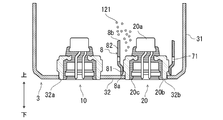
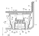
- FIG. 2 is a diagram for explaining a structure in the vicinity of the second ignition device 20 in the gas generator 100 according to the first embodiment.
- FIG. 2 shows a state before the operation of the second ignition device 20.
- the second ignition device 20 is fixed to the second fitting hole 32b formed in the bottom plate portion 32 of the lower shell 3.
- the second igniter 20 is formed of a second igniter 20a, a collar 20b attached to the housing 1 to support the second igniter 20a, and a resin material for fixing the second igniter 20a to the collar 20b.
- the holding portion 20c is provided.
- the second ignition device 20 is an example of an “ignition device”.
- the second igniter 20a has a metal cup body C2 containing an igniter and a pair of energizing pins EP2 and EP2 for receiving an electric current supply from the outside.
- the second igniter 20a is operated by the current supplied to the pair of energizing pins EP2 and EP2, the igniter is burned and the combustion product is discharged to the outside of the cup body C2.
- the collar 20b has a substantially tubular shape, and is fixed to the bottom plate portion 32 of the lower shell 3 by being welded to the bottom plate portion 32 with the lower end portion fitted in the second fitting hole 32b. .. As a result, the second igniter 20 is attached to the housing 1.
- the collar 20b does not have to be separate from the housing 1, and may be integrally molded with the housing (in this example, the lower shell 3 of the housing 1).
- the holding portion 20c is a resin member that fixes the second igniter 20a to the collar 20b by being interposed between the second igniter 20a and the collar 20b.
- the holding portion 20c covers the lower portion of the second igniter 20a and engages with the inner peripheral surface of the collar 20b so that at least a part of the cup body C2 is exposed from the holding portion 20c.
- the second igniter 20a is fixed to the igniter 20a.
- the entire cup body C2 may be overmolded by the holding portion 20c. That is, the entire cup body C2 may be covered with resin.
- the holding portion 20c is formed with a connector insertion space 20d into which a connector (not shown) for supplying power from an external power source can be inserted into the pair of energizing pins EP2 and EP2.
- the holding portion 20c covers and holds a part of the pair of energizing pins EP2 and EP2 so that the lower ends of the pair of energizing pins EP2 and EP2 are exposed in the connector insertion space 20d.
- the holding portion 20c maintains the insulating property between the pair of energizing pins EP2 and EP2.
- the container 7 is a second transmission which is an internal space of the container 7 together with the surrounding member 8 fixed in the housing 1 so as to surround the second ignition device 20 and the surrounding member 8 by being fitted with the surrounding member 8. It is formed including a lid member 9 that defines the fire chamber S2.
- the surrounding member 8 is formed in a tubular shape, and is arranged between the bottom plate portion 32 of the lower shell 3 and the dividing wall portion 41 of the partition wall member 4 so that the axial direction thereof coincides with the vertical direction of the gas generator 100. Has been done.
- One end of the surrounding member 8 is fixed in the housing 1 so as to surround the second ignition device 20.
- the surrounding member 8 has a press-fitting portion 81 including one end portion (lower end portion 8a) and an extending portion 82 including the other end portion (upper end portion 8b) and having an inner diameter larger than that of the press-fitting portion 81.
- the lower end portion 8a of the surrounding member 8 is in contact with the bottom plate portion 32 of the lower shell 3, and the collar 20b of the second ignition device 20 is press-fitted into the press-fitting portion 81.
- the extending portion 82 extends upward toward the dividing wall portion 41 of the partition wall member 4 without coming into contact with the second ignition device 20.
- the "axial direction” refers to the axial direction of the surrounding member 8 unless otherwise specified.
- the surrounding member 8 is surrounded so that the vertical position (that is, the position in the axial direction) of the upper end portion 8b of the surrounding member 8 is located within the vertical range of the cup body C2 of the second igniter 20a.
- the height of the member 8 is set.
- the upper end portion 8b of the surrounding member 8 may be located at a height equal to or higher than the upper end surface of the cup body C2. That is, the surrounding member 8 may extend to at least the range of the cup body C2 of the second igniter 20a in the axial direction. As a result, at least a part of the cup body C2 of the second igniter 20a is surrounded by the surrounding member 8.
- the lid member 9 is fitted with the surrounding member 8 so as to close the opening formed in the upper end portion 8b of the surrounding member 8. More specifically, the lid member 9 is formed at one end of the tubular fitting wall portion 91 that fits with the surrounding member 8 and the fitting wall portion 91, and closes the opening of the surrounding member 8. Part 92 and. In the container 7, the surrounding member 8 and the lid member 9 are fitted so that the outer peripheral surface of the extending portion 82 of the surrounding member 8 and the inner peripheral surface of the fitting wall portion 91 of the lid member 9 face each other. There is. That is, the fitting wall portion 91 is externally fitted to the surrounding member 8.
- the second firebox S2 is defined by being surrounded by the surrounding member 8 and the lid member 9.
- the second firebox S2 contains a second firebox 121 that is ignited by the operation of the second ignition device 20.
- the second explosive agent 121 is an example of a “combustible product”.
- a communication hole 71 for communicating the second firebox S2 and the external space of the container 7 is formed in the container 7, and the external space of the container 7 is formed so as to surround the container 7.
- the second gas generating agent 120 is arranged.
- the portion of the dot pattern indicated by reference numeral 72 in FIG. 2 indicates a portion (fitting portion) of the container 7 in which the surrounding member 8 and the lid member 9 are fitted. That is, the fitting portion 72 is a portion where the surrounding member 8 and the lid member 9 overlap each other. In the gas generator 100, the fitting portion 72 is a portion including a part of the extending portion 82 of the surrounding member 8 and a part of the fitting wall portion 91 of the lid member 9.
- the communication hole 71 is provided in the accommodating device 7 except for the fitting portion 72 in which the surrounding member 8 and the lid member 9 are fitted before the operation of the second ignition device 20. It is formed.
- a plurality of communication holes 71 are provided along the circumferential direction of the surrounding member 8 at a portion of the surrounding member 8 other than the fitting portion 72 that fits with the lid member 9 before the operation of the second ignition device 20. They are formed side by side at equal intervals. As the shape of the communication hole 71, various shapes such as a circle, an ellipse, and a rectangle can be selected.
- the communication hole 71 may be a slit formed at the end of the surrounding member 8 in addition to the through hole. Further, the communication hole 71 may be formed so as to exhibit a communication function at least when the second ignition device 20 is operated, and may be closed before the operation of the second ignition device 20.
- the communication hole 71 may be a hole that is closed by the sealing tape before the operation of the second ignition device 20 and the seal tape is cleaved by the combustion pressure when the second ignition device 20 is operated. Further, the communication hole 71 may be a fragile portion formed to be thinner than the other portion so that the communication hole 71 is preferentially cleaved over the other portion when a load due to the combustion pressure is applied.
- the closing portion 92 of the lid member 9 faces the divided wall portion 41 of the partition wall member 4.
- a protruding portion 921 protruding toward the dividing wall portion 41 is formed.
- the protruding portion 921 is received by a receiving portion 412 formed in the divided wall portion 41.
- a gap G1 is formed between the closed portion 92 and the divided wall portion 41.
- the distance D1 between the closing portion 92 and the dividing wall portion 41 is set so that the second gas generating agent 120 does not enter the gap G1.
- a gap G2 is also formed between the upper end surface of the cup body C2 of the second igniter 20a and the protruding portion 921.
- the second explosive agent 121 may be present in this gap G2.
- the gap G2 is filled with the second explosive agent 121 so as not to form an unnecessary space.
- the filter F1 has a tubular shape, the upper end portion thereof is supported by the top plate portion 22 of the upper shell 2, and the lower end portion is supported by the divided wall portion 41 of the partition wall member 4. In the state, it is arranged between the first gas generating agent 110 and the gas discharge hole 13.
- the filter F1 is configured to allow combustion gas to pass through, and the combustion gas generated in the first combustion chamber 11 and the second combustion chamber 12 is cooled by passing through the filter F1. At this time, the filter F1 filters the combustion gas by collecting the combustion residue of the combustion gas. Further, an annular gap 15 is formed between the filter F1 and the upper peripheral wall portion 21 in which the gas discharge hole 13 is formed.
- the first gas generating agent 110 and the second gas generating agent 120 a gas generating agent having a relatively low combustion temperature can be used.
- the combustion temperature of the first gas generating agent 110 and the second gas generating agent 120 can be set in the range of 1000 to 1700 ° C.
- known ones including, for example, guanidine nitrate (41% by weight), basic copper nitrate (49% by weight), a binder and additives are used.
- the first gas generating agent 110 and the second gas generating agent 120 may have various shapes such as granules, pellets, cylinders, and disks.
- the first explosive agent 111 and the second explosive agent 121 a gas generator having good ignitability and having a higher combustion temperature than the first gas generating agent 110 and the second gas generating agent 120 can be used.
- the combustion temperature of the first explosive agent 111 and the second explosive agent 121 can be set in the range of 1700 to 3000 ° C.
- known ones containing, for example, nitroguanidine (34% by weight) and strontium nitrate (56% by weight) can be used.
- the first explosive agent 111 and the second explosive agent 121 can adopt various shapes such as granules, pellets, cylinders, and disks.
- the gas generator 100 is configured so that the combustion gas of the second explosive agent 121 can be reliably discharged from the communication hole 71.
- the operation of the gas generator 100 will be mainly described with respect to the operation when the second ignition device 20 is operated and the second explosive charge 121 is burned.
- the case where the second igniter 20 operates later than the first igniter 10 (that is, after the first igniter 10 operates) will be described.
- the first ignition device 10 when the first ignition device 10 is activated, the first combustion charge 111 housed in the first transmission chamber S1 of the first combustion chamber 11 is burned, and the combustion gas is generated.
- the partition member 6 is burned and removed by the combustion gas of the first explosive agent 111, the combustion gas comes into contact with the first gas generating agent 110 and the first gas generating agent 110 is ignited.
- the first gas generating agent 110 burns, high-temperature and high-pressure combustion gas is generated in the first combustion chamber 11.
- this combustion gas passes through the filter F1, the combustion gas is cooled and the combustion residue is collected.
- the combustion gas of the first gas generating agent 110 cooled and filtered by the filter F1 passes through the gap 15, breaks the sealing tape 14, and is discharged from the gas discharge hole 13 to the outside of the housing 1.
- FIG. 3 is a diagram showing a case where the second ignition device 20 is operated in the gas generator 100 according to the first embodiment and the lid member 9 moves in a direction away from the surrounding member 8. In this case, the combustion pressure of the second explosive agent 121 acts on the lid member 9 in the axial direction upward, so that the lid member 9 moves upward along the axial direction.
- FIG. 3 shows a state in which the lid member 9 has moved until it comes into contact with the partition wall member 4.
- the combustion pressure of the second explosive agent 121 acts not only on the upper side in the axial direction but also on the outer side in the radial direction of the surrounding member 8. Therefore, for example, the surrounding member 8 and the lid member 9 may be deformed by the combustion pressure on the outer side in the radial direction, so that the movement of the lid member 9 in the direction away from the surrounding member 8 may be hindered.
- FIG. 4 is a diagram showing a case where the lid member 9 does not move in the direction away from the surrounding member 8 even when the second ignition device 20 is operated in the gas generator 100 according to the first embodiment.
- the second igniter 20 when the second igniter 20 operates and the lid member 9 moves in the direction away from the surrounding member 8 due to the combustion pressure of the second igniter 121, the second igniter 20 is fitted after the operation.
- the axial length L2 of the portion 72 is shorter than the axial length L1 (see FIG. 2) of the fitting portion 72 before the operation of the second ignition device 20. That is, the range of the fitting portion 72 after the operation of the second ignition device 20 is narrower than that before the operation of the second ignition device 20.
- the lid member 9 when the lid member 9 does not move in the direction away from the surrounding member 8 even when the second ignition device 20 operates, the axial direction of the fitting portion 72 after the second ignition device 20 operates.
- the length L3 of the second ignition device 20 is the same as the axial length L1 of the fitting portion 72 before the operation of the second ignition device 20. That is, the range of the fitting portion 72 after the operation of the second ignition device 20 does not change from that before the operation of the second ignition device 20. In this way, regardless of whether or not the lid member 9 moves in the direction away from the surrounding member 8 when the second ignition device 20 is operated, the range of the fitting portion 72 is the range before the operation of the second ignition device 20. Does not spread.
- a communication hole 71 is formed in a portion of the surrounding member 8 other than the fitting portion 72 that fits with the lid member 9 before the operation of the second ignition device 20. Therefore, the communication hole 71 is not closed by the lid member 9 before the operation of the second ignition device 20. Then, as described with reference to FIGS. 3 and 4, the range of the fitting portion 72 does not expand regardless of whether or not the lid member 9 moves in the direction away from the surrounding member 8, so that the communication hole 71 is formed. The lid member 9 does not block the second ignition device 20 during or after the operation. Further, of the surrounding member 8 and the lid member 9, a communication hole 71 is formed in the surrounding member 8 fixed in the housing 1.
- the lid member 9 is provided by fitting with the surrounding member 8, when the second ignition device 20 is operated, the lid member 9 moves in a direction away from the surrounding member 8 and is a component other than the surrounding member 8 (this In the example, the partition member 4) may come into contact (interference).
- the surrounding member 8 since the surrounding member 8 is fixed in the housing 1, even if the second ignition device 20 is operated, it does not come into contact with any part other than the lid member 9. Since the communication hole 71 is formed in such a surrounding member 8, when the second ignition device 20 is operated, the surrounding member 8 may come into contact with a part other than the lid member 9 to close the communication hole 71. Absent. As a result, as shown in FIGS.
- the combustion gas of the second propellant 121 generated in the second firebox S2 by the operation of the second ignition device 20 communicates without being hindered by the lid member 9. It is surely discharged to the external space of the container 7 through the hole 71. That is, it is avoided that the combustion gas is cut off.
- the communication hole 71 is closed by the sealing tape, the combustion gas is discharged by cleaving the sealing tape.
- the combustion gas of the second explosive agent 121 discharged from the communication hole 71 burns the second gas generating agent 120 arranged around the container 7, and a high-temperature and high-pressure combustion gas is generated in the second combustion chamber 12. Will be done.
- the combustion gas of the second gas generating agent 120 flows into the first combustion chamber 11 through the flow hole 55, is cooled and filtered by the filter F1, passes through the gap 15, and flows from the gas discharge hole 13 to the outside of the housing 1. It is released.
- the combustion gases of the first gas generating agent 110 and the second gas generating agent 120 flow into the airbag (not shown) after being discharged to the outside of the housing 1.
- the expansion of the airbag creates a cushion between the occupant and the rigid structure, protecting the occupant from impact.
- the amount of movement of the lid member 9 depends on the distance D1 between the closing portion 92 and the dividing wall portion 41 and the pressure of each combustion chamber. It is assumed depending on the degree of deformation of the housing 1.
- the gas generator 100 when the axial length L1 (see FIG. 2) of the fitting portion 72 before the operation of the second ignition device 20 is activated by the second ignition device 20. It is set to be longer than the amount of movement of the lid member 9 in the axial direction assumed in.
- the second ignition device 20 is activated and the lid member 9 moves in the direction away from the surrounding member 8, that is, even when the lid member 9 moves upward along the axial direction, the surrounding member 8 And the lid member 9 are maintained. That is, it is suppressed that the lid member 9 comes off from the surrounding member 8 and the combustion gas is discharged from the opening of the surrounding member 8. As a result, the combustion gas passes through the communication hole 71 more reliably, and the second explosive agent 121 is stably burned.
- FIG. 5 is a flowchart of a gas generator assembly method (hereinafter, simply referred to as “assembly method”) according to the first embodiment.
- assembly method simply referred to as “assembly method”.
- the first ignition device 10, the second ignition device 20, the upper shell 2, the lower shell 3, the partition wall member 4, the inner cylinder member 5, the partition member 6, and the surrounding members are enclosed.
- a member 8, a lid member 9, a filter F1, and a retainer R1 are prepared.
- the surrounding member 8 is formed with a communication hole 71, which is a through hole, in advance.
- the communication hole 71 is formed, for example, by drilling a tubular member as a base material.
- FIG. 6 is a diagram showing a state of the mounting process of the ignition device.
- each ignition device is inserted into the lower shell 3 through an opening formed at the upper end of the lower peripheral wall portion 31 of the lower shell 3.
- the first ignition device 10 is fixed to the lower shell 3 by being welded to the bottom plate portion 32 in a state of being fitted into the first fitting hole 32a.
- the second ignition device 20 is fixed to the lower shell 3 by being welded to the bottom plate portion 32 in a state of being fitted in the second fitting hole 32b. As a result, the second ignition device 20 is attached to the lower shell 3.
- FIG. 7 is a diagram showing a state of the mounting process of the surrounding member.
- the surrounding member 8 is inserted into the lower shell 3 through the opening formed at the upper end of the lower peripheral wall portion 31 of the lower shell 3.
- the collar 20b of the second ignition device 20 is press-fitted into the press-fitting portion 81 so that the lower end portion 8a of the surrounding member 8 comes into contact with the bottom plate portion 32 of the lower shell 3.
- the lower end portion 8a of the surrounding member 8 is fixed.
- FIG. 8 is a diagram showing a state of the filling process of the second explosive.
- the second explosive is filled inside the surrounding member 8 through the opening formed in the upper end portion 8b of the surrounding member 8.
- the second igniter 121 is filled between the second igniter 20 and the siege member 8. ..
- the second explosive charge 121 is not pressed against the second ignition device 20 (particularly, the cup body C2 protruding from the holding portion 20C), and the second explosive charge 121 is damaged. It is suppressed. Further, when the siege member 8 extends to a height of the cup body C2 or higher of the second ignition device 20, the second igniter 121 is less likely to spill from the inside of the siege member 8 when the second igniter is filled. As a result, the filling work can be easily performed.
- FIG. 9 is a diagram showing a state of the lid member attaching process
- FIG. 10 is a diagram showing a state in which the lid member is attached.
- the surrounding member 8 and the fitting wall portion 91 of the lid member 9 are fitted, so that the opening formed in the upper end portion 8b of the surrounding member 8 is a lid.
- the lid member 9 is attached so as to be closed by the closing portion 92 of the member 9.
- the container 7 is formed, and the second firebox S2, which is the internal space thereof, is defined.
- the surrounding member 8 and the lid member 9 are fitted so that the communication hole 71 is located at a portion other than the fitting portion 72 between the surrounding member 8 and the lid member 9. ..
- the communication hole 71 communicates the second fire chamber S2 with the external space of the container 7, and the combustion gas of the second explosive 121 is sent to the outside of the container 7. It can be discharged into the space.
- step S106 after fixing the inner cylinder member 5 so as to surround the first ignition device 10, the second gas generating agent 120 is filled inside the lower shell 3. After that, the partition member 4 is attached. At this time, the terminal portion 43 of the partition wall member 4 is arranged on the upper end surface of the lower peripheral wall portion 31 of the lower shell 3, and the fitting wall portion 42 of the partition wall member 4 is arranged so that the inner cylinder member 5 penetrates the through hole 411. The lower peripheral wall portion 31 of the lower shell 3 is fitted. After that, the inner cylinder member 5 is filled with the first explosive charge 111, and the partition member 6 is arranged on the first explosive charge 111.
- the filter F1 is arranged on the divided wall portion 41 of the partition wall member 4, the first gas generating agent 110 is filled inside the filter F1, and the retainer R1 is arranged on the first gas generating agent 110.
- the housing 1 is formed by fitting the lower peripheral wall portion 31 into the outer fitting wall portion 24 until the abutting portion 23 of the upper shell 2 abuts on the terminal portion 43 of the partition wall member 4.
- the contact portions of the upper shell 2 and the lower shell 3 are joined by a joining method (for example, welding or the like) suitable for moisture-proofing or the like of the gas generating agent filled inside.
- a joining method for example, welding or the like
- the portion of the accommodator 7 excluding the fitting portion 72 in which the surrounding member 8 and the lid member 9 are fitted before the operation of the second ignition device 20 is performed.
- a communication hole 71 is formed in the second fire chamber S2 to communicate with the external space of the container 7.
- a communication hole is formed in a fitting portion of the surrounding member with the lid member, and the communication hole is closed by the lid member before the operation of the ignition device, and the ignition device is used.
- the communication hole is opened. That is, it is premised that the lid member moves in the direction away from the surrounding member when the ignition device is activated.
- the surrounding member or the lid member is deformed due to the combustion pressure of the gas generating agent and the movement of the lid member is hindered, the communication blocked by the lid member is blocked.
- the holes may not open as desired. Then, there is a risk that the combustion performance becomes unstable and the parts are damaged due to the pressure increase.
- the portion other than the fitting portion 72 where the surrounding member 8 and the lid member 9 are fitted before the operation of the second ignition device 20 is performed in the surrounding member 8.
- the communication hole 71 is formed. That is, the communication hole 71 is formed so as to avoid the fitting portion 72 before the operation of the second ignition device 20. Then, the range of the fitting portion between the surrounding member 8 and the lid member 9 does not expand regardless of whether or not the lid member 9 moves in the direction away from the surrounding member 8. Therefore, in the gas generator 100, it is possible to prevent the communication hole 71 from being blocked by the lid member 9 regardless of whether or not the lid member moves away from the surrounding member when the second ignition device 20 is operated. it can.
- the surrounding member 8 and the lid member 9 by forming the communication hole 71 in the surrounding member 8 fixed in the housing 1, the surrounding member 8 becomes the lid member 9 when the second ignition device 20 is operated. It is also possible to prevent the communication hole 71 from being blocked by contacting a component other than the above. As a result, the gas generator 100 can reliably discharge the combustion gas of the second explosive agent 121 from the communication hole 71 to the external space of the accommodator 7. As a result, in the gas generator 100, desired combustion performance can be stably obtained, and damage to parts due to a pressure increase in the second firebox S2 can be suppressed.
- the length L1 in the axial direction of the fitting portion 72 before the operation of the second ignition device 20 is set, and the second ignition device 20 is operated to reduce the second explosive charge 121. It is set longer than the amount of movement of the lid member 9 with respect to the surrounding member 8 in the axial direction, which is assumed in the case of combustion. As a result, even when the second ignition device 20 is activated and the lid member 9 moves in a direction away from the surrounding member 8, the fitting between the surrounding member 8 and the lid member 9 is maintained. That is, it is possible to prevent the lid member 9 from coming off the surrounding member 8 and the combustion gas being discharged from the opening of the surrounding member 8. As a result, the combustion gas passes through the communication hole 71 more reliably, and the second explosive agent 121 burns stably. As a result, the combustion performance can be further stabilized.
- the second explosive agent 121 is filled inside the surrounding member 8 with the surrounding member 8 fixed so as to surround the second ignition device 20. If the second igniter 20 is to be pushed into the container filled with the second explosive 121 first, the closing portion 92 is turned down and the opening of the fitting wall portion 91 is turned up. It is necessary to fit the surrounding member 8 from above with the lid member 9 filled with the second explosive agent 121. For that purpose, it is necessary to temporarily invert the parts so that the state shown in FIG. 9 is inverted upside down, which complicates the assembly process. Further, there is a concern that the second explosive agent 121 is pressurized by the second ignition device 20 (cup body C2) and is damaged.
- the second ignition device 20 is arranged inside the surrounding member 8 and then the second explosive is filled. Therefore, it is not necessary to turn the parts upside down as described above, and the gas generator can be assembled in order from the bottom, and the assembly process can be simplified. Further, it is possible to prevent the second explosive charge 121 from being pressurized to the second ignition device 20 at the time of assembling the gas generator 100, and to suppress damage to the second explosive charge 121.
- the surrounding member 8 and the lid member 9 are fitted so that the communication hole 71 is located at a portion other than the fitting portion 72, so that the gas generator after completion has a second transmission. The combustion gas of the explosive 121 can be reliably discharged from the communication hole 71 to the external space of the container 7.
- FIG. 11 is a diagram for explaining a structure in the vicinity of the second ignition device 20 in the gas generator 100A according to the first modification of the first embodiment.
- FIG. 11 shows a state before the operation of the second ignition device 20.
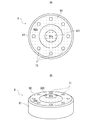
- 12A and 12B are views showing the lid member 9 according to the first modification of the first embodiment, FIG. 12A is a top view, and FIG. 12B is a perspective view.
- the gas generator 100A differs from the gas generator 100 in that a communication hole is formed in the lid member, and is generally different from the gas generator 100 in other respects. It is the same.
- a protruding portion 921 protruding toward the dividing wall portion 41 of the partition wall member 4 is formed in the center of the closing portion 92 of the lid member 9.
- the end surface portion 92a which is the top surface of the protruding portion 921, and the end surface portion 92a
- a concave concave surface portion 92b is formed on the outer surface of the closed portion 92 of the lid member 9 (the surface opposite to the surface defining the second firebox S2).
- the end surface portion 92a which is the top surface of the protruding portion 921
- the end surface portion 92a On the other hand, a concave concave surface portion 92b is formed.
- FIGS. 12A and 12B the range of the end face portion 92a and the range of the concave surface portion 92b are shown separately according to the difference in the dot pattern. As shown in FIGS.
- the concave surface portion 92b is formed in an annular shape so as to surround the end surface portion 92a, and is connected to the outer peripheral surface of the fitting wall portion 91.
- the concave surface portion 92b has a flow path FP1 formed between the closing portion 92 and the partition wall member 4 which is a member facing the closing portion 92 and connected to the space outside the container 7 in the radial direction of the surrounding member 8.
- the partition wall member 4 does not have the receiving portion 412 as shown in FIG. 2, and the divided wall portion 41 is formed substantially flat.
- a plurality of communication holes 71 are formed in the concave surface portion 92b so as to surround the end surface portion 91a so as to be arranged at equal intervals along the circumferential direction. That is, the communication hole 71 is a portion of the lid member 9 excluding the fitting portion 72 that fits with the surrounding member 8 before the operation of the second ignition device 20, and is formed in a portion recessed with respect to the end face portion 92a. Has been done.
- FIG. 13 is a diagram showing a case where the second ignition device 20 is operated in the gas generator 100A according to the first modification of the first embodiment and the lid member 9 moves in a direction away from the surrounding member 8.
- FIG. 13 shows a state in which the lid member 9 has moved until it comes into contact with the partition wall member 4.
- a communication hole 71 is formed in a portion of the lid member 9 other than the fitting portion 72 that fits with the surrounding member 8 before the operation of the second ignition device 20. Therefore, it is suppressed that the communication hole 71 is blocked by the surrounding member 8 regardless of whether or not the lid member 9 moves away from the surrounding member 8 when the second ignition device 20 is operated.
- the lid member 9 moves in a direction away from the surrounding member 8 due to the combustion pressure of the second explosive agent 121 when the second ignition device 20 is operated, the lid member 9 is a member facing the closing portion 92. It approaches a certain partition wall member 4. Then, as shown in FIG. 13, when the lid member 9 and the partition wall member 4 come into contact with each other, the end surface portion 92a of the closing portion 92 comes into contact with the dividing wall portion 41 of the partition wall member 4.
- the concave surface portion 92b in which the communication hole 71 is formed is recessed with respect to the end surface portion 92a, even when the closing portion 92 and the partition wall member 4 come into contact with each other, the concave surface portion 92b and the partition wall member 4 A flow path FP1 is secured between the two and the communication gas so that the combustion gas can flow. That is, it is also suppressed that the communication hole 71 is blocked by the partition wall member 4 when the second ignition device 20 is operated. As a result, as shown in FIG. 13, the combustion gas of the second explosive agent 121 generated in the second firebox S2 when the second ignition device 20 is activated is blocked by the surrounding member 8 and the partition wall member 4.
- the gas generator 100A when the communication hole 71 is formed in the closing portion 92 of the lid member 9, when the closing portion 92 comes into contact with the partition wall member 4 when the second ignition device 20 is operated. Even so, similarly to the gas generator 100, the combustion gas of the second explosive agent 121 can be reliably discharged from the communication hole 71 to the external space of the reservoir 7. As a result, desired combustion performance can be stably obtained, and damage to parts due to an increase in pressure can be suppressed.
- FIG. 14 is a diagram for explaining a structure in the vicinity of the second ignition device 20 in the gas generator 100B according to the second modification of the first embodiment.
- FIG. 14 shows a state before the operation of the second ignition device 20.
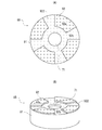
- 15A and 15B are views showing the lid member 9B according to the second modification of the first embodiment, FIG. 15A is a top view, and FIG. 15B is a perspective view.
- the gas generator 100B differs from the gas generator 100 in that a communication hole is formed in the inner wall of the groove formed in the lid member. However, it is almost the same in other respects.
- a groove 922 extending radially from the center of the closed portion 92 is formed on the outer surface of the closed portion 92 of the lid member 9B according to the second modification. ing.
- the groove 922 is connected to the space outside the container 7B in the radial direction of the surrounding member 8.
- a concave surface portion 92b which is the inner wall of the groove 922
- an end surface portion 92a which is the surface of the portion excluding the groove 922, are formed on the outer surface of the closed portion 92.
- the concave surface portion 92b is recessed with respect to the end surface portion 92a and is connected to the outer peripheral surface of the fitting wall portion 91.
- the concave surface portion 92b forms a flow path FP1 that connects the closing portion 92 and the partition wall member 4, which is a member facing the closing portion 92, with the space outside the container 7 in the radial direction of the surrounding member 8.
- a communication hole 71 is formed in the center of the concave surface portion 92b. That is, the communication hole 71 is a portion of the lid member 9B excluding the fitting portion 72 that fits with the surrounding member 8 before the operation of the second ignition device 20, and is formed in a portion recessed with respect to the end face portion 92a. Has been done.
- FIG. 16 is a diagram showing a case where the second ignition device 20 is operated in the gas generator 100B according to the first modification of the first embodiment and the lid member 9B moves in a direction away from the surrounding member 8.
- FIG. 15 shows a state in which the lid member 9B has moved until it comes into contact with the partition wall member 4.
- a communication hole 71 is formed in the lid member 9B except for the fitting portion 72 that fits with the surrounding member 8 before the operation of the second ignition device 20.
- the concave surface portion 92b in which the communication hole 71 is formed is recessed with respect to the end surface portion 92a.
- the end surface portion 92a of the closing portion 92 is in contact with the partition wall member 4, while the concave surface portion 92b and the partition wall member 4 are burned.
- the flow path FP1 is secured so that the gas can flow. That is, it is also suppressed that the communication hole 71 is blocked by the partition wall member 4 when the second ignition device 20 is operated.
- the combustion gas of the second explosive agent 121 generated in the second firebox S2 when the second ignition device 20 is activated is the surrounding member 8 and the partition wall. It is discharged to the external space of the container 7 through the communication hole 71 without being hindered by the member 4.
- the gas generator 100B also has the same effect as the gas generator 100A. That is, when the communication hole 71 is formed in the closing portion 92 of the lid member 9B, even if the closing portion 92 comes into contact with the partition wall member 4 when the second ignition device 20 is operated, the second explosive agent 121 The combustion gas of the above can be reliably discharged from the communication hole 71 to the external space of the container 7. As a result, desired combustion performance can be stably obtained, and damage to parts due to an increase in pressure can be suppressed.
- FIG. 17 is a diagram for explaining a structure in the vicinity of the second ignition device 20 in the gas generator 100C according to the third modification of the first embodiment.
- FIG. 17 shows a state before the operation of the second ignition device 20.
- the gas generator 100C is different from the gas generator 100 in that the fitting wall portion of the lid member is fitted in the surrounding member, and is substantially the same in other respects. More specifically, in the container 7 according to the third modification, the surrounding surface of the extending portion 82 of the surrounding member 8 and the inner peripheral surface of the fitting wall portion 91 of the lid member 9C face each other with the surrounding member 8.
- the container 7 is formed by fitting with the lid member 9. Even in such a gas generator 100C, the same effect as that of the gas generator 100 is obtained.
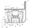
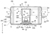
- FIG. 18 is an axial sectional view of the gas generator 200 according to the second embodiment.
- the gas generator 200 in the gas generator 200, one combustion chamber 16 and one ignition device 30 are housed in a housing 201 formed by welding and fixing an upper shell 202 and a lower shell 203.
- the gas generator 200 includes an ignition device 30, an accommodator 207, a filter F1, and a housing 201 accommodating them.
- the gas generator 200 according to the second embodiment will be described focusing on the differences from the gas generator 100, and detailed description will be omitted by assigning the same reference numerals to the same configurations as the gas generator 100. To do.
- Both ends of the housing 201 are closed in the axial direction by joining the metal upper shell 202 and the lower shell 203, each of which is formed in a substantially cylindrical shape with a bottom, with their open ends facing each other. It is formed in a short cylindrical shape.
- the upper shell 202 has a tubular upper peripheral wall portion 221 and a top plate portion 222 that closes the upper end of the upper peripheral wall portion 221, and forms an internal space by these.
- An opening of the upper shell 202 is formed by the lower end of the upper peripheral wall portion 221.
- a joint portion 223 extending outward in the radial direction is connected to the lower end portion of the upper peripheral wall portion 221.
- the lower shell 203 has a tubular lower peripheral wall portion 231 and a bottom plate portion 232 that closes the lower end of the lower peripheral wall portion 231, thereby forming an internal space. Further, the bottom plate portion 232 is formed with a fitting hole 232b to which the ignition device 30 is fixed. A joint portion 233 extending outward in the radial direction is connected to the upper end portion of the lower peripheral wall portion 231.
- the joint portion 223 of the upper shell 202 and the joint portion 233 of the lower shell 203 are overlapped and joined by laser welding or the like to form a short cylindrical housing 201 in which both ends in the axial direction are closed. Further, a plurality of gas discharge holes 13 closed by the sealing tape 14 are formed side by side in the circumferential direction on the upper peripheral wall portion 221 of the upper shell 202.
- the ignition device 30 is arranged at a substantially central position in the internal space of the housing 201 and is fixed to the fitting hole 232b of the lower shell 203.
- the ignition device 30 has the same configuration as the second ignition device 20 described in the first embodiment. That is, the ignition device 30 includes an igniter 30a, a collar 30b attached to the housing 201 to support the igniter 30a, and a holding portion 30c made of a resin material for fixing the igniter 30a to the collar 30b. , Equipped with. A connector insertion space 30d into which a connector (not shown) can be inserted is formed in the holding portion 30c.
- the ignition device 30 is an example of an “ignition device”.
- the accommodating device 207 accommodating the ignition device 30 has the same configuration as the accommodating device 7 described in the first embodiment. That is, the housing 207 is a fire transmission room which is an internal space of the housing 207 together with the surrounding member 208 by fitting the surrounding member 208 fixed in the housing 201 so as to surround the ignition device 30 and the surrounding member 208. It is formed including a lid member 209 that defines S3.
- the surrounding member 208 is formed in a tubular shape, and is arranged between the bottom plate portion 232 of the lower shell 203 and the top plate portion 222 of the upper shell 202 so that the axial direction thereof coincides with the vertical direction of the gas generator 100. Has been done.
- the lower end portion 8a of the surrounding member 208 is fixed in the housing 201 so as to surround the ignition device 30.
- the lower end portion 8a of the surrounding member 208 is in contact with the bottom plate portion 232 of the lower shell 203, and the collar 30b of the ignition device 30 is press-fitted into the surrounding member 208.
- the lid member 209 is fitted with the surrounding member 208 so as to close the opening formed in the upper end portion 8b of the surrounding member 208.
- the lid member 209 includes a tubular fitting wall portion 91 that fits with the surrounding member 208, and a closing portion 92 that is formed at one end of the fitting wall portion 91 and closes the opening of the surrounding member 208. .. In the container 207, the fitting wall portion 91 is fitted to the surrounding member 208.
- the firebox S3 is defined by being surrounded by the surrounding member 208 and the lid member 209.
- the firebox S3 contains a firebox 131 that is ignited by the operation of the ignition device 30.
- the accommodator 207 is formed with a communication hole 71 that communicates the fire transmission room S3 with the external space of the accommodator 207.
- the gas generating agent 130 is arranged so as to surround the container 207, and the filter F1 is arranged so as to surround the gas generating agent 130.
- a communication hole 71 is formed to communicate the chamber S3 with the external space of the container 207. More specifically, the communication hole 71 is formed in a portion of the surrounding member 208 other than the fitting portion 72 that fits with the lid member 209 before the ignition device 30 is operated.
- the closing portion 92 of the lid member 209 faces the top plate portion 222 of the upper shell 202, and a gap G1 is formed between the closing portion 92 and the top plate portion 222. There is. The distance D1 between the closing portion 92 and the top plate portion 222 is set so that the gas generating agent 130 does not enter the gap G1.
- a retainer or cushion may be arranged in the gap G1.
- FIG. 19 is a diagram showing a case where the ignition device 30 is operated in the gas generator 200 according to the second embodiment and the lid member 209 moves in a direction away from the surrounding member 208. As shown in FIG. 19, the lid member 209 moves upward along the axial direction due to the combustion pressure of the gunpowder 131. In the gas generator 200, a communication hole 71 is formed in a portion of the lid member 209 other than the fitting portion 72 that fits with the surrounding member 208 before the ignition device 30 is operated.
- the communication hole 71 is suppressed from being blocked by the surrounding member 208 regardless of whether or not the lid member 209 moves away from the surrounding member 208 when the ignition device 30 is operated. Further, of the surrounding member 208 and the lid member 209, since the communication hole 71 is formed in the surrounding member 208 fixed in the housing 201, the surrounding member 208 is other than the lid member 209 when the ignition device 30 is operated. It is also suppressed that the communication hole 71 is blocked by contacting the parts of the above. As a result, the gas generator 200 can reliably discharge the combustion gas of the fire transmission room S3 from the communication hole 71 to the external space of the accommodator 207. As a result, desired combustion performance can be stably obtained, and damage to parts due to an increase in pressure can be suppressed.
- the combustion gas of the gunpowder 131 discharged from the communication hole 71 burns the gas generating agent 130 arranged around the container 207, and high-temperature and high-pressure combustion gas is generated in the combustion chamber 16. After being cooled and filtered by the filter F1, the combustion gas of the gas generating agent 130 passes through the gap 15, breaks the sealing tape 14, and is discharged from the gas discharge hole 13 to the outside of the housing 201.
- the axial length L1 of the fitting portion 72 before the operation of the ignition device 30 is the ignition device 30. Is set longer than the amount of movement of the lid member 209 with respect to the surrounding member 208 in the axial direction, which is assumed when As a result, even when the ignition device 30 is activated and the lid member 209 moves in a direction away from the surrounding member 208, the fitting between the surrounding member 208 and the lid member 209 is maintained, and the lid member 209 is moved from the surrounding member 209. It is possible to suppress deviation from 208. As a result, the combustion gas passes through the communication hole 71 more reliably, and the combustion performance can be more stabilized.
- the method of assembling the gas generator according to the first embodiment can be adopted. That is, in filling the explosive charge 131, the explosive charge 131 is filled inside the encircling member 208 with the surrounding member 208 fixed so as to surround the ignition device 30. Since the igniter 131 is filled after arranging the igniter 30 inside the surrounding member 208, it is possible to prevent the igniter 131 from being pressurized to the igniter 30 when assembling the gas generator 200, and the explosive 131 is damaged. Can be suppressed.
- FIG. 20 is a diagram for explaining a structure in the vicinity of the ignition device 30 in the gas generator 200D according to the modified example of the second embodiment.
- FIG. 20 shows the state of the ignition device 30 before operation.
- the gas generator 200D differs from the gas generator 200 in that a communication hole is formed in the lid member, and is substantially the same in other respects.
- a protruding portion 921 protruding toward the top plate portion 222 of the upper shell 202 is formed in the center of the closing portion 92 of the lid member 209D according to the modified example.
- an end surface portion 92a which is the top surface of the protruding portion 921
- a concave surface portion 92b recessed with respect to the end surface portion 92a are formed on the outer surface of the closing portion 92 of the lid member 209D.
- the concave surface portion 92b is formed in an annular shape so as to surround the end surface portion 92a, and is connected to the outer peripheral surface of the fitting wall portion 91.
- the concave surface portion 92b is formed with a flow path FP1 that connects the closing portion 92 and the upper shell 202, which is a member facing the closed portion 92, with the space outside the container 207 in the radial direction of the surrounding member 208.
- a plurality of communication holes 71 are formed in the concave surface portion 92b so as to surround the end surface portion 91a so as to be arranged at equal intervals along the circumferential direction. That is, the communication hole 71 is a portion of the lid member 209D excluding the fitting portion 72 that fits with the surrounding member 8 before the operation of the second ignition device 20, and is formed in a portion recessed with respect to the end face portion 92a. Has been done.
- the communication hole 71 is formed in the lid member 209D except for the fitting portion 72, the communication hole 71 is a surrounding member when the second ignition device 20 is operated. Blockage by 208 is suppressed. Further, the concave surface portion 92b in which the communication hole 71 is formed is recessed with respect to the end surface portion 92a. Therefore, even when the closed portion 92 and the upper shell 202 (more specifically, the top plate portion 222) come into contact with each other, the combustion gas can flow between the concave portion 92b and the upper shell 202. Road FP1 is secured. That is, it is suppressed that the communication hole 71 is blocked by the upper shell 202 when the ignition device 30 is operated.
- the combustion gas of the gunpowder 131 generated in the firebox S3 by the operation of the ignition device 30 passes through the communication hole 71 and enters the external space of the container 207 without being hindered by the surrounding member 208 or the upper shell 202. It is discharged.
- the gas generator 200D even when the communication hole 71 is formed in the closing portion 92 of the lid member 209D and the closing portion 92 comes into contact with the upper shell 202 due to the operation of the ignition device 30.
- the combustion gas of the explosive agent 131 can be reliably discharged from the communication hole 71 to the external space of the container 207. As a result, desired combustion performance can be stably obtained, and damage to parts due to an increase in pressure can be suppressed.
- the explosive for burning the gas generating agent is shown as an example of the "combustible material", but in the technique of the present disclosure, the ignition device burns the gas generating agent without using the explosive. It can also be applied to type gas generators. In that case, the gas generating agent corresponds to the "combustion”.
- the "combustion product” is not limited to the combustion gas generated by the combustion of the gas generating agent or the explosive, and may be a flame.
- the bottom plate portions 32 and 332 and the collars 20b and 30b are separately fixed by welding or the like is shown, but those in which these are integrally formed in advance can also be used. ..
- the form and arrangement of the communication holes are not limited to the above-described embodiments, and known techniques can be used.
- the communication hole may be localized so that the flame of the propellant is preferentially supplied to the region of the external space of the container where the gas generating agent is arranged in a large amount.
Landscapes
- Physics & Mathematics (AREA)
- Fluid Mechanics (AREA)
- Engineering & Computer Science (AREA)
- Mechanical Engineering (AREA)
- Air Bags (AREA)
Abstract
ガス発生器は、点火装置が作動することで着火される燃焼物が収容された収容器を備え、収容器は、点火装置を取り囲むようにハウジング内に固定された包囲部材と、包囲部材と嵌合することで包囲部材と共に収容器の内部空間を画定する蓋部材と、を含み、収容器のうち、点火装置の作動前における包囲部材と蓋部材との嵌合部位を除く部位には、収容器の内部空間と外部空間とを連通する連通孔が、燃焼物の燃焼生成物を収容器の外部空間へ排出可能となるように形成されている。
Description
本発明は、ガス発生器、及びガス発生器の組立方法に関する。
点火器を作動させることで燃焼室内に収容されたガス発生剤を燃焼させ、該ガス発生剤の燃焼ガスを発生させるガス発生器においては、その燃焼ガスの排出量や排出時間等をパラメータとする性能(以下、「燃焼性能」という)を所望の性能とするためには、当該収容されたガス発生剤を所望するように燃焼させることが重要である。このようなガス発生器として、例えば、特許文献1には、ハウジングの内部に下端が固定された筒状のカップと該カップの上端の開口部を閉塞するようにカップと嵌合したキャップとによって第2室が形成され、第2室の内部に点火装置とガス発生剤とが配置され、カップの側面には孔が形成されたガス発生器が開示されている。このガス発生器は、点火装置が作動する前の状態では該孔がキャップによって閉塞されており、点火装置が作動するとガス発生剤の燃焼圧力によりキャップがカップに沿って上方へ摺動することで該孔が開口し、ガス発生剤の燃焼ガスが該孔を介して第2室の外部に放出されるように構成されている。
上記のガス発生器は、ガス発生剤の燃焼圧力を受けたキャップがカップに沿って上方へ摺動することを前提としている。しかしながら、ガス発生剤の燃焼圧力は、カップの軸方向上側のみでなく径方向外側へも作用することになる。そのため、径方向外側の燃焼圧力によりカップやキャップが変形することでキャップの摺動が阻害され、これにより、キャップによって塞がれた孔が所望通りに開口しないことがある。その結果、燃焼性能の不安定化や第2室の圧力上昇による部品の損傷が生じる虞がある。
本開示の技術は、上述の問題に鑑みてなされたものであり、その目的は、ガス発生器において、所望の燃焼性能を安定して得ることが可能な技術を提供することである。
上記課題を解決するために、本開示の技術は、以下の構成を採用した。即ち、本開示の技術は、点火装置と、前記点火装置が取り付けられたハウジングと、前記ハウジング内に配置され、前記点火装置が作動することで着火される燃焼物が収容された収容器と、を備えるガス発生器であって、前記収容器は、前記点火装置を取り囲むように前記ハウジング内に固定された包囲部材と、前記包囲部材と嵌合することで前記包囲部材と共に前記収容器の内部空間を画定する蓋部材と、を含み、前記収容器のうち、前記点火装置の作動前において前記包囲部材と前記蓋部材とが嵌合する嵌合部位を除く部位には、前記収容器の内部空間と外部空間とを連通する連通孔が、前記燃焼物の燃焼生成物を前記収容器の外部空間へ排出可能となるように形成されている、ガス発生器である。
つまり、本開示のガス発生器では、包囲部材に形成された開口部を蓋部材が塞ぐことで収容器が形成され、点火装置の作動前における包囲部材と蓋部材との嵌合部位を避けるように連通孔が形成されている。ここで、点火装置が作動すると、燃焼物の燃焼圧力を受けた蓋部材が包囲部材から外れる方向に移動する場合と移動しない場合とがあるが、何れの場合であっても包囲部材と蓋部材との嵌合部位の範囲が広がることがない。そのため、ガス発生器によると、点火装置の作動前における嵌合部位を避けるように連通孔を形成することで、点火装置が作動したときに蓋部材が包囲部材から外れる方向へ移動するか否かに関わらず、連通孔が嵌合部位によって閉塞されることを抑制できる。これにより、燃焼物の燃焼生成物を連通孔から収容器の外部空間へ確実に排出することができる。その結果、ガス発生器において、所望の燃焼性能を安定して得ることができる。
また、本開示のガス発生器において、前記包囲部材は、筒状に形成され、且つ、前記点火装置を取り囲むようにその一端部が前記ハウジング内に固定され、前記蓋部材は、前記包囲部材の他端部に形成された開口部を閉塞するように前記包囲部材と嵌合し、前記点火装置の作動前における前記嵌合部位の前記包囲部材の軸方向における長さは、前記燃焼物が燃焼した場合に想定される、前記包囲部材の軸方向における前記蓋部材の前記包囲部材に対する移動量よりも長く設定されていてもよい。
点火装置が作動し、燃焼物の燃焼圧力により蓋部材が包囲部材から外れようとする場合、蓋部材は、包囲部材の軸方向に沿って移動することとなる。包囲部材の軸方向において、嵌合部位の長さを想定される蓋部材の移動量よりも長く設定しておくことで、蓋部材が包囲部材から外れる方向に移動した場合であっても、包囲部材と蓋部材との嵌合を維持することができる。そのため、点火装置が作動したときに蓋部材が包囲部材から外れて燃焼生成物が包囲部材の開口部から排出されることを抑制できる。その結果、より確実に燃焼生成物が連通孔を通ることとなり、燃焼性能をより安定化できる。
更に、本開示のガス発生器において、前記連通孔が、前記包囲部材のうちの前記嵌合部位を除いた部位に形成されていてもよい。
蓋部材は、包囲部材との嵌合により設けられているため、点火装置が作動したときに包囲部材から外れる方向へ移動して包囲部材以外の部品と接触する場合がある。一方、包囲部材は、ハウジング内に固定されているため、点火装置が作動しても蓋部材以外の部品に接触することがない。そのため、包囲部材と蓋部材とのうち、包囲部材に連通孔を形成することで、点火装置が作動したときに包囲部材が蓋部材以外の部品に接触して連通孔が閉塞されることが抑制される。その結果、より確実に燃焼物の燃焼生成物を連通孔から収容器の外部空間へ排出することができる。
更に、本開示のガス発生器において、前記蓋部材は、前記嵌合部位を含む筒状の嵌合壁部と、前記嵌合壁部の一端部に形成され、前記包囲部材の前記開口部を閉塞する閉塞部と、を含み、前記閉塞部の外面には、端面部と、前記端面部に対して凹んだ凹面部と、が形成され、前記凹面部は、前記ガス発生器において前記閉塞部と対向する部材との間に、前記収容器の外側の空間と繋がる流路を形成し、前記連通孔は、前記凹面部に形成されていてもよい。
蓋部材が包囲部材から外れる方向に移動する場合、蓋部材は、ガス発生器において閉塞部と対向する部材に接近することとなる。連通孔が形成されている凹面部が凹んでいるため、閉塞部と閉塞部に対向する部材とが接触した場合であっても、凹面部と該部材との間には、流路が確保される。これにより、連通孔を蓋部材の閉塞部に形成した場合において、点火装置が作動したときに閉塞部が閉塞部と対向する部材に接触した場合であっても、燃焼物の燃焼生成物を連通孔から収容器の外部空間へ確実に排出することができる。
上記のガス発生器において、前記端面部は、前記閉塞部の中央において突出した突出部の頂面として形成され、前記凹面部は、前記端面部を取り囲むように環状に形成されていてもよいし、前記凹面部は、前記閉塞部の中央部から放射状に延びる溝の内壁として形成されていてもよい。
また、本開示の技術は、ガス発生器の組立方法としても特定することができる。即ち、本開示の技術は、点火装置と、前記点火装置が取り付けられたハウジングと、前記ハウジング内に配置され、前記点火装置が作動することで着火される燃焼物が収容された収容器と、を備えるガス発生器の組立方法であって、前記点火装置と、前記点火装置が取り付けられるべき部位を含み且つ前記ハウジングの一部を構成するハウジング部品と、互いに嵌合することで前記収容器の内部空間を画定する包囲部材及び蓋部材と、を準備することと、前記ハウジング部品に前記点火装置を取り付けることと、前記ハウジング部品に前記点火装置が取り付けられた部材に対して、前記点火装置を取り囲むように前記包囲部材を固定することと、前記包囲部材が固定された状態で、前記包囲部材の内側に前記燃焼物を充填することと、前記包囲部材の内側に前記燃焼物が充填された状態で、前記包囲部材と前記蓋部材とのうちの少なくとも一方に設けられた貫通孔である連通孔が、前記収容器の内部空間と外部空間とを連通すると共に前記燃焼物の燃焼生成物を前記収容器の外部空間へ排出可能となるように、前記包囲部材と前記蓋部材との嵌合部位を除く部位に前記連通孔が位置するように前記包囲部材と前記蓋部材とを嵌合させることと、を含む、ガス発生器の組立方法である。
本開示のガス発生器の組立方法によると、包囲部材の内側に点火装置を配置した後に燃焼物を充填することとなるため、ガス発生器の組み立て時に燃焼物が点火装置によって加圧されることを回避し、以て燃焼物の破損を抑制できる。また、嵌合部位を除く部位に連通孔が位置するように包囲部材と蓋部材とを嵌合させることで、完成後のガス発生器においては燃焼物の燃焼生成物を連通孔から収容器の外部空間へ確実に排出することができる。
なお、本開示の技術は、点火装置を1つのみ備えたシングルタイプのガス発生器にも、点火装置を2つ以上備えるタイプのガス発生器にも適用することができる。
本開示の技術によれば、ガス発生器において、所望の燃焼性能を安定して得ることが可能となる。
以下に、図面を参照して本開示の実施形態に係るガス発生器について説明する。なお、各実施形態における各構成及びそれらの組み合わせ等は一例であって、本発明の主旨から逸脱しない範囲内で、適宜、構成の付加、省略、置換、及びその他の変更が可能である。本開示は、実施形態によって限定されることはなく、請求の範囲によってのみ限定される。
<実施形態1>
実施形態1として、本開示に係る技術をデュアルタイプのガス発生器に適用した場合について説明する。図1は、実施形態1に係るガス発生器100の軸方向断面図である。図1では、ガス発生器100の作動前の状態が示されている。ガス発生器100は、2つの点火装置を備えるデュアルタイプのガス発生器として構成されている。
実施形態1として、本開示に係る技術をデュアルタイプのガス発生器に適用した場合について説明する。図1は、実施形態1に係るガス発生器100の軸方向断面図である。図1では、ガス発生器100の作動前の状態が示されている。ガス発生器100は、2つの点火装置を備えるデュアルタイプのガス発生器として構成されている。
[全体構成]
図1に示すように、ガス発生器100は、第1点火装置10と、第2点火装置20と、隔壁部材4と、内筒部材5と、仕切部材6と、収容器7と、フィルタF1と、リテーナR1と、これらを収容するハウジング1と、を備えている。ハウジング1の内部空間は、隔壁部材4によって、第1点火装置10及び第1ガス発生剤110が収容される第1燃焼室11と、第2点火装置20及び第2ガス発生剤120が収容される第2燃焼室12と、に分割されている。
図1に示すように、ガス発生器100は、第1点火装置10と、第2点火装置20と、隔壁部材4と、内筒部材5と、仕切部材6と、収容器7と、フィルタF1と、リテーナR1と、これらを収容するハウジング1と、を備えている。ハウジング1の内部空間は、隔壁部材4によって、第1点火装置10及び第1ガス発生剤110が収容される第1燃焼室11と、第2点火装置20及び第2ガス発生剤120が収容される第2燃焼室12と、に分割されている。
ガス発生器100は、第1点火装置10と第2点火装置20とを作動させることで、最終的には各燃焼室に収容されたガス発生剤を燃焼させ、その燃焼生成物である燃焼ガスをハウジング1に形成されたガス排出孔13から放出するように構成されている。より具体的には、センサ(図示せず)が衝撃を感知すると、所定信号が各点火装置に送られ、第1点火装置10が作動し、第1点火装置10の作動タイミング以降に第2点火装置20が作動する。ガス発生器100は、第1点火装置10の作動による第1ガス発生剤110の燃焼と第2点火装置20の作動による第2ガス発生剤120の燃焼とによって、比較的多量の燃焼ガスを生成し、その燃焼ガスをガス排出孔13から外部に放出することができる。実施形態1においては、第2点火装置20は、第1点火装置10とは独立して作動するものであり、作動する場合には第1点火装置10の作動時以降の所定のタイミングで作動する。即ち、第2点火装置20は、第1点火装置10と同時に、あるいは第1点火装置10の作動に遅れて作動する。各燃焼室内のガス発生剤の燃焼のタイミングは、これらの燃焼ガスの外部への放出タイミングに相関し、結果的にガス発生器の出力を示すこととなる。そのため、各点火装置の作動タイミングは、衝突の際の衝撃の大きさに基づき決定される。センサ(図示せず)が感知した衝撃の大きさに応じて、衝撃が弱い場合には第2点火装置20が作動せずに第1点火装置10のみが作動することや、衝撃が強い場合には第1点火装置10と第2点火装置20とが同時に作動することがある。
図1に示すように、第2燃焼室12には収容器7が配置されており、収容器7の内部空間である第2伝火室S2には、第2点火装置20と第2点火装置20の作動により着火する第2伝火薬121とが収容されている。また、収容器7には、第2伝火室S2と収容器7の外部空間とを連通する連通孔71が形成されている。第2伝火薬121の燃焼生成物である燃焼ガスは、連通孔71を通って収容器7の外部空間に排出され、第2ガス発生剤120を燃焼させる。詳細については後述するが、実施形態1に係るガス発生器100は、第2伝火薬121の燃焼ガスを連通孔71から確実に排出可能となるように構成されている。以下、ガス発生器100の各構成について詳しく説明する。なお、本明細書では、「点火装置が作動する」とは、詳細には、点火装置が備える点火器が作動することを意味する。
[ハウジング]
ハウジング1は、夫々が有底略円筒状に形成された金属製の上部シェル2及び下部シェル3が互いの開口端同士を向き合わせた状態で接合されることによって、軸方向の両端が閉塞した短尺円筒状に形成されている。ここで、ハウジング1の軸方向に沿う方向をガス発生器100の上下方向と定義し、上部シェル2側(即ち、図1における上側)をガス発生器100の上側とし、下部シェル3側(即ち、図1における下側)をガス発生器100の下側とする。
ハウジング1は、夫々が有底略円筒状に形成された金属製の上部シェル2及び下部シェル3が互いの開口端同士を向き合わせた状態で接合されることによって、軸方向の両端が閉塞した短尺円筒状に形成されている。ここで、ハウジング1の軸方向に沿う方向をガス発生器100の上下方向と定義し、上部シェル2側(即ち、図1における上側)をガス発生器100の上側とし、下部シェル3側(即ち、図1における下側)をガス発生器100の下側とする。
上部シェル2は、筒状の上側周壁部21と該上側周壁部21の上端を閉塞する天板部22とを有し、これらにより内部空間を形成する。上部シェル2の内部空間には、第1ガス発生剤110が収容される。天板部22は、上面視で概ね円形状を有している。上側周壁部21は、天板部22の周縁から概ね垂直に延在することで、筒状の周壁を形成する。上側周壁部21の上端側には天板部22が繋がり、上側周壁部21の下端側には突き当て部23を介して外嵌壁部24が繋がっている。外嵌壁部24の下端部によって上部シェル2の開口部が形成されている。また、外嵌壁部24の内径は、上側周壁部21の内径よりも大きく設定されている。
下部シェル3は、上部シェル2と共にハウジング1の一部を構成する部品であり、点火装置が取り付けられるべき部位を含む部品である。下部シェル3は、「ハウジング部品」の一例である。下部シェル3は、筒状の下側周壁部31と該下側周壁部31の下端を閉塞する底板部32とを有し、これらにより内部空間を形成する。下部シェル3の内部空間には、第2ガス発生剤120が収容される。底板部32は、上部シェル2の天板部22と同様に、上面視で概ね円形状を有している。また、底板部32には、第1点火装置10が固定される第1嵌合孔32aと第2点火装置20が固定される第2嵌合孔32bとが設けられている。下側周壁部31は、底板部32の周縁から概ね垂直に延在することで、筒状の周壁を形成する。下側周壁部31の下端側には底板部32が繋がり、下側周壁部31の上端部によって下部シェル3の開口部が形成されている。また、下側周壁部31の外径は、上部シェル2の外嵌壁部24の内径と概ね同等に形成されており、下側周壁部31が上部シェル2の外嵌壁部24に嵌入されている。
これら上部シェル2と下部シェル3とによって、ハウジング1が形成されている。上部シェル2の上側周壁部21には、ハウジング1の内部空間と外部空間とを連通するガス排出孔13が周方向に並んで複数形成されている。ガス排出孔13は、シールテープ14により閉塞されている。このシールテープ14としては、片面に粘着部材が塗布されたアルミニウム箔等が利用される。これにより、ハウジング1の気密性が確保されている。
[隔壁部材]
隔壁部材4は、第1燃焼室11と第2燃焼室12とをハウジング1内に画定する部材である。隔壁部材4は、円盤状の分割壁部41と筒状の嵌入壁部42と終端部43とを有する。分割壁部41は、ハウジング1の軸方向と概ね直交する方向に延在してハウジング1の内部空間を上下に分割している。嵌入壁部42は、分割壁部41に繋がると共に該分割壁部41の周縁から下部シェル3の下側周壁部31の内周面に沿って概ね上方へ延在している。終端部43は、嵌入壁部42に繋がると共に該嵌入壁部42の上端からハウジング1の径方向外側に延在している。図1に示すように、終端部43が下部シェル3の下側周壁部31の上端面に配置されることで、隔壁部材4が下部シェル3によって支持されている。また、分割壁部41には、内筒部材5が貫通する貫通孔411が形成されている。また、分割壁部41における、後述する収容器7の突出部921に対向する位置には、突出部921を受け入れるように上側に凹んだ受け入れ部412が形成されている。
隔壁部材4は、第1燃焼室11と第2燃焼室12とをハウジング1内に画定する部材である。隔壁部材4は、円盤状の分割壁部41と筒状の嵌入壁部42と終端部43とを有する。分割壁部41は、ハウジング1の軸方向と概ね直交する方向に延在してハウジング1の内部空間を上下に分割している。嵌入壁部42は、分割壁部41に繋がると共に該分割壁部41の周縁から下部シェル3の下側周壁部31の内周面に沿って概ね上方へ延在している。終端部43は、嵌入壁部42に繋がると共に該嵌入壁部42の上端からハウジング1の径方向外側に延在している。図1に示すように、終端部43が下部シェル3の下側周壁部31の上端面に配置されることで、隔壁部材4が下部シェル3によって支持されている。また、分割壁部41には、内筒部材5が貫通する貫通孔411が形成されている。また、分割壁部41における、後述する収容器7の突出部921に対向する位置には、突出部921を受け入れるように上側に凹んだ受け入れ部412が形成されている。
図1に示すように、ハウジング1の内部空間は、隔壁部材4によって、ハウジング1の軸方向における天板部22側(上側)に位置する第1燃焼室11と、ハウジング1の軸方向における底板部32側(下側)に位置する第2燃焼室12と、に分割される。第1燃焼室11には、第1点火装置10と第1ガス発生剤110とが収容される。第1燃焼室11における天板部22と第1ガス発生剤110との間には、第1ガス発生剤110の振動を抑制するために、第1ガス発生剤110を付勢するリテーナR1が配置されている。また、第1燃焼室11は、ガス排出孔13を介してハウジング1の外部空間(即ち、ガス発生器100の外部空間)と連通している。第2燃焼室12には、第2点火装置20と第2ガス発生剤120とが収容される。
[第1点火装置]
第1点火装置10は、下部シェル3の底板部32に形成された第1嵌合孔32aに固定されている。第1点火装置10は、後述する第2点火装置20と同様の構成を有する。図1に示すように、第1点火装置10は、第1点火器10aを含んで構成されており、第1点火器10aは、点火薬が収容された金属製のカップ体C1と、外部から電流の供給を受けるための一対の通電ピンEP1,EP1と、を有する。一対の通電ピンEP1,EP1に供給される電流により第1点火器10aが作動することで、該点火薬が燃焼し、その燃焼生成物がカップ体C1の外部に放出される。
第1点火装置10は、下部シェル3の底板部32に形成された第1嵌合孔32aに固定されている。第1点火装置10は、後述する第2点火装置20と同様の構成を有する。図1に示すように、第1点火装置10は、第1点火器10aを含んで構成されており、第1点火器10aは、点火薬が収容された金属製のカップ体C1と、外部から電流の供給を受けるための一対の通電ピンEP1,EP1と、を有する。一対の通電ピンEP1,EP1に供給される電流により第1点火器10aが作動することで、該点火薬が燃焼し、その燃焼生成物がカップ体C1の外部に放出される。
[内筒部材]
内筒部材5は、第1点火装置10を取り囲むようにハウジング1内に固定された筒状の部材である。内筒部材5は、下部周壁部51と接続部52と上部周壁部53と先端部54とを有する。下部周壁部51は、下端が下部シェル3の底板部32に接触すると共に上方へ延在している。接続部52は、下部周壁部51に繋がっている。上部周壁部53は、接続部52に繋がると共に下部周壁部51よりも縮径して接続部52から上方へ延在している。先端部54は、上部周壁部53に繋がると共に該上部周壁部53から内側に曲がって終端し、その端縁によって内筒部材5の開口部を形成している。図1に示すように、内筒部材5は、下部周壁部51が下部シェル3の底板部32における第1嵌合孔32aの近傍に接触するように、第1嵌合孔32aに固定された第1点火装置10と嵌合している。下部周壁部51及び上部周壁部53は、上部シェル2の天板部22に向かって上方へ延在した状態となっている。また、内筒部材5は、上部周壁部53及び先端部54が第1燃焼室11内に突出するように貫通孔411を貫通した状態で、隔壁部材4と嵌合している。また、内筒部材5の内部空間は、先端部54に形成された開口部を介して上部シェル2の上側周壁部21の内部空間と繋がることで、第1燃焼室11の一部を形成している。また、内筒部材5の下部周壁部51には、内筒部材5の内部空間(即ち、第1燃焼室11)と第2燃焼室12とを連通する流通孔55が複数形成されている。
内筒部材5は、第1点火装置10を取り囲むようにハウジング1内に固定された筒状の部材である。内筒部材5は、下部周壁部51と接続部52と上部周壁部53と先端部54とを有する。下部周壁部51は、下端が下部シェル3の底板部32に接触すると共に上方へ延在している。接続部52は、下部周壁部51に繋がっている。上部周壁部53は、接続部52に繋がると共に下部周壁部51よりも縮径して接続部52から上方へ延在している。先端部54は、上部周壁部53に繋がると共に該上部周壁部53から内側に曲がって終端し、その端縁によって内筒部材5の開口部を形成している。図1に示すように、内筒部材5は、下部周壁部51が下部シェル3の底板部32における第1嵌合孔32aの近傍に接触するように、第1嵌合孔32aに固定された第1点火装置10と嵌合している。下部周壁部51及び上部周壁部53は、上部シェル2の天板部22に向かって上方へ延在した状態となっている。また、内筒部材5は、上部周壁部53及び先端部54が第1燃焼室11内に突出するように貫通孔411を貫通した状態で、隔壁部材4と嵌合している。また、内筒部材5の内部空間は、先端部54に形成された開口部を介して上部シェル2の上側周壁部21の内部空間と繋がることで、第1燃焼室11の一部を形成している。また、内筒部材5の下部周壁部51には、内筒部材5の内部空間(即ち、第1燃焼室11)と第2燃焼室12とを連通する流通孔55が複数形成されている。
[仕切部材]
図1に示すように、内筒部材5の内部には、内筒部材5の内部空間を上下に仕切る、仕切部材6が配置されている。内筒部材5の内部空間のうち、仕切部材6よりも下側(第1点火装置10側)の空間である第1伝火室S1には、第1伝火薬111が、第1ガス発生剤110が混在することなく収容されている。第1伝火薬111は、第1点火装置10の作動により着火し、その燃焼ガスによって第1ガス発生剤110を燃焼させる。仕切部材6は、第1伝火薬111の燃焼ガスによる第1ガス発生剤110の着火を妨げないように、第1伝火薬111の燃焼ガスにより速やかに燃焼、溶融あるいは消滅する材料で形成されている。また、金網等の多孔部材を仕切部材6として使用してもよい。仕切部材6の上下位置は、第1燃焼室11内に収容される第1伝火薬111及び第1ガス発生剤110の量に応じて、適宜変更することができる。
図1に示すように、内筒部材5の内部には、内筒部材5の内部空間を上下に仕切る、仕切部材6が配置されている。内筒部材5の内部空間のうち、仕切部材6よりも下側(第1点火装置10側)の空間である第1伝火室S1には、第1伝火薬111が、第1ガス発生剤110が混在することなく収容されている。第1伝火薬111は、第1点火装置10の作動により着火し、その燃焼ガスによって第1ガス発生剤110を燃焼させる。仕切部材6は、第1伝火薬111の燃焼ガスによる第1ガス発生剤110の着火を妨げないように、第1伝火薬111の燃焼ガスにより速やかに燃焼、溶融あるいは消滅する材料で形成されている。また、金網等の多孔部材を仕切部材6として使用してもよい。仕切部材6の上下位置は、第1燃焼室11内に収容される第1伝火薬111及び第1ガス発生剤110の量に応じて、適宜変更することができる。
[第2点火装置]
図2は、実施形態1に係るガス発生器100における第2点火装置20付近の構造を説明するための図である。図2では、第2点火装置20の作動前の状態が示されている。図2に示すように、第2点火装置20は、下部シェル3の底板部32に形成された第2嵌合孔32bに固定されている。第2点火装置20は、第2点火器20aと、ハウジング1に取り付けられて第2点火器20aを支持するカラー20bと、カラー20bに対して第2点火器20aを固定する、樹脂材料で形成された保持部20cと、を備える。第2点火装置20は、「点火装置」の一例である。
図2は、実施形態1に係るガス発生器100における第2点火装置20付近の構造を説明するための図である。図2では、第2点火装置20の作動前の状態が示されている。図2に示すように、第2点火装置20は、下部シェル3の底板部32に形成された第2嵌合孔32bに固定されている。第2点火装置20は、第2点火器20aと、ハウジング1に取り付けられて第2点火器20aを支持するカラー20bと、カラー20bに対して第2点火器20aを固定する、樹脂材料で形成された保持部20cと、を備える。第2点火装置20は、「点火装置」の一例である。
第2点火器20aは、点火薬が収容された金属製のカップ体C2と、外部から電流の供給を受けるための一対の通電ピンEP2,EP2と、を有する。一対の通電ピンEP2,EP2に供給される電流により第2点火器20aが作動することで、該点火薬が燃焼し、その燃焼生成物がカップ体C2の外部に放出される。
カラー20bは、概ね筒状を有しており、下端部が第2嵌合孔32bに嵌入された状態で底板部32と溶接されることで、下部シェル3の底板部32に固定されている。これにより、第2点火装置20がハウジング1に取り付けられている。なお、カラー20bは、ハウジング1と別体でなくともよく、ハウジング(本例では、ハウジング1の下部シェル3)と一体に成形されたものであってもよい。
保持部20cは、第2点火器20aとカラー20bとの間に介装されることで、カラー20bに対して第2点火器20aを固定する樹脂製の部材である。保持部20cは、第2点火器20aの下部を覆うと共にカラー20bの内周面と係合することで、カップ体C2の少なくとも一部が保持部20cから露出した状態となるように、カラー20bに対して第2点火器20aを固定する。但し、保持部20cによってカップ体C2の全体がオーバーモールドされていてもよい。即ち、カップ体C2の全体が樹脂に覆われた状態であってもよい。また、保持部20cには、一対の通電ピンEP2,EP2に外部電源からの電力を供給するコネクタ(図示せず)を挿入可能なコネクタ挿入空間20dが形成されている。保持部20cは、一対の通電ピンEP2,EP2の下端がコネクタ挿入空間20d内に露出するように、一対の通電ピンEP2,EP2の一部を覆い、保持している。保持部20cによって、一対の通電ピンEP2,EP2同士の絶縁性が保たれている。
[収容器]
収容器7は、第2点火装置20を取り囲むようにハウジング1内に固定された包囲部材8と、包囲部材8と嵌合することで包囲部材8と共に収容器7の内部空間である第2伝火室S2を画定する蓋部材9と、を含んで形成されている。
収容器7は、第2点火装置20を取り囲むようにハウジング1内に固定された包囲部材8と、包囲部材8と嵌合することで包囲部材8と共に収容器7の内部空間である第2伝火室S2を画定する蓋部材9と、を含んで形成されている。
包囲部材8は、筒状に形成されており、その軸方向がガス発生器100の上下方向と一致するように下部シェル3の底板部32と隔壁部材4の分割壁部41との間に配置されている。包囲部材8は、第2点火装置20を取り囲むように、一端部がハウジング1内に固定されている。包囲部材8は、その一端部(下端部8a)を含む圧入部81と、その他端部(上端部8b)を含み圧入部81よりも内径の大きな延在部82と、を有している。包囲部材8の下端部8aは下部シェル3の底板部32に接触しており、圧入部81には第2点火装置20のカラー20bが圧入されている。延在部82は、第2点火装置20と接触することなく隔壁部材4の分割壁部41に向かって上方へ延在している。なお、以下の説明において、「軸方向」とは、特に指定しない限りは包囲部材8の軸方向のことを指す。
ここで、図2に示すように、包囲部材8の上端部8bの上下位置(即ち、軸方向における位置)が第2点火器20aのカップ体C2の上下の範囲内に位置するように、包囲部材8の高さが設定されている。なお、包囲部材8の上端部8bは、カップ体C2の上端面以上の高さに位置してもよい。つまり、包囲部材8は、軸方向において、少なくとも第2点火器20aのカップ体C2の範囲にまで延びていればよい。これにより、第2点火器20aのカップ体C2の少なくとも一部が包囲部材8によって取り囲まれている。
蓋部材9は、包囲部材8の上端部8bに形成された開口部を閉塞するように、包囲部材8と嵌合している。より具体的には、蓋部材9は、包囲部材8と嵌合する筒状の嵌合壁部91と、嵌合壁部91の一端部に形成され、包囲部材8の開口部を閉塞する閉塞部92と、を含む。収容器7では、包囲部材8における延在部82の外周面と蓋部材9における嵌合壁部91の内周面とが向き合うようにして、包囲部材8と蓋部材9とが嵌合している。つまり、嵌合壁部91が包囲部材8に外嵌している。
この包囲部材8と蓋部材9とによって囲まれることで、第2伝火室S2が画定されている。第2伝火室S2には、第2点火装置20の作動により着火する第2伝火薬121が収容されている。第2伝火薬121は、「燃焼物」の一例である。収容器7には、第2伝火室S2と収容器7の外部空間とを連通する連通孔71が形成されており、収容器7の外部空間には、収容器7を取り囲むようにして、第2ガス発生剤120が配置されている。
ここで、図2において符号72で示すドットパターンの部位は、収容器7のうち包囲部材8と蓋部材9とが嵌合している部位(嵌合部位)を示す。つまり、嵌合部位72は、包囲部材8と蓋部材9とが重なり合っている部位である。ガス発生器100では、嵌合部位72は、包囲部材8における延在部82の一部と蓋部材9における嵌合壁部91の一部とを含む部位となっている。このとき、図2に示すように、連通孔71は、収容器7のうち、第2点火装置20の作動前において包囲部材8と蓋部材9とが嵌合する嵌合部位72を除く部位に形成されている。より詳細には、包囲部材8のうち第2点火装置20の作動前において蓋部材9と嵌合する嵌合部位72を除く部位に、複数の連通孔71が包囲部材8の周方向に沿って等間隔に並んで形成されている。連通孔71の形状としては、円形、楕円形、矩形等、種々の形状を選択することができる。連通孔71は、貫通孔以外にも、包囲部材8の端部に形成されたスリットであってもよい。また、連通孔71は、少なくとも第2点火装置20の作動時に連通機能を発現するように形成されていればよく、第2点火装置20の作動前には閉塞されていてもよい。例えば、連通孔71は、第2点火装置20の作動前にはシールテープによって閉塞され、第2点火装置20が作動すると燃焼圧力によりシールテープが開裂する孔であってもよい。また、連通孔71は、燃焼圧力による荷重が作用したときに他の部位よりも優先的に開裂するように、他の部位よりも厚みが薄く形成された、脆弱部であってもよい。
また、図2に示すように、蓋部材9の閉塞部92は、隔壁部材4の分割壁部41に対向している。閉塞部92の中央には、分割壁部41に向かって突出した突出部921が形成されている。突出部921は、分割壁部41に形成された受け入れ部412に受け入れられている。この閉塞部92と分割壁部41との間には、隙間G1が形成されている。隙間G1に第2ガス発生剤120が入り込まないように、閉塞部92と分割壁部41との距離D1が設定されている。また、第2点火器20aのカップ体C2の上端面と突出部921との間にも隙間G2が形成されている。この隙間G2には、第2伝火薬121が存在していてもよい。特に、包囲部材8がカップ体C2の上端面以上の高さまで延びている場合は、不要な空間を形成しないように、この隙間G2は第2伝火薬121で埋められる。
[フィルタ]
図1に示すように、フィルタF1は、筒形状を有しており、その上端部が上部シェル2の天板部22に支持され、下端部が隔壁部材4の分割壁部41に支持された状態で、第1ガス発生剤110とガス排出孔13との間に配置されている。フィルタF1は、燃焼ガスが通過可能に構成されており、第1燃焼室11及び第2燃焼室12で発生した燃焼ガスは、フィルタF1を通過することで冷却される。このとき、フィルタF1は、燃焼ガスの燃焼残渣を捕集することで燃焼ガスを濾過する。また、フィルタF1とガス排出孔13が形成された上側周壁部21との間には、環状の間隙15が形成されている。
図1に示すように、フィルタF1は、筒形状を有しており、その上端部が上部シェル2の天板部22に支持され、下端部が隔壁部材4の分割壁部41に支持された状態で、第1ガス発生剤110とガス排出孔13との間に配置されている。フィルタF1は、燃焼ガスが通過可能に構成されており、第1燃焼室11及び第2燃焼室12で発生した燃焼ガスは、フィルタF1を通過することで冷却される。このとき、フィルタF1は、燃焼ガスの燃焼残渣を捕集することで燃焼ガスを濾過する。また、フィルタF1とガス排出孔13が形成された上側周壁部21との間には、環状の間隙15が形成されている。
[ガス発生剤]
第1ガス発生剤110や第2ガス発生剤120には、比較的燃焼温度の低いガス発生剤を使用することができる。第1ガス発生剤110や第2ガス発生剤120の燃焼温度は、1000~1700℃の範囲に設定することができる。このような第1ガス発生剤110や第2ガス発生剤120としては、例えば、硝酸グアニジン(41重量%)、塩基性硝酸銅(49重量%)及びバインダーや添加物を含む、公知のものを用いることができる。また、第1ガス発生剤110や第2ガス発生剤120には、例えば顆粒状、ペレット状、円柱状、ディスク状等、種々の形状を採用できる。
第1ガス発生剤110や第2ガス発生剤120には、比較的燃焼温度の低いガス発生剤を使用することができる。第1ガス発生剤110や第2ガス発生剤120の燃焼温度は、1000~1700℃の範囲に設定することができる。このような第1ガス発生剤110や第2ガス発生剤120としては、例えば、硝酸グアニジン(41重量%)、塩基性硝酸銅(49重量%)及びバインダーや添加物を含む、公知のものを用いることができる。また、第1ガス発生剤110や第2ガス発生剤120には、例えば顆粒状、ペレット状、円柱状、ディスク状等、種々の形状を採用できる。
[伝火薬]
第1伝火薬111や第2伝火薬121としては、着火性が良く、第1ガス発生剤110や第2ガス発生剤120よりも燃焼温度の高いガス発生剤を使用することができる。第1伝火薬111や第2伝火薬121の燃焼温度は、1700~3000℃の範囲に設定することができる。このような第1伝火薬111や第2伝火薬121としては、例えば、ニトログアニジン(34重量%)、硝酸ストロンチウム(56重量%)を含む、公知のものを用いることができる。また、第1伝火薬111や第2伝火薬121は、例えば顆粒状、ペレット状、円柱状、ディスク状等、種々の形状を採用できる。
第1伝火薬111や第2伝火薬121としては、着火性が良く、第1ガス発生剤110や第2ガス発生剤120よりも燃焼温度の高いガス発生剤を使用することができる。第1伝火薬111や第2伝火薬121の燃焼温度は、1700~3000℃の範囲に設定することができる。このような第1伝火薬111や第2伝火薬121としては、例えば、ニトログアニジン(34重量%)、硝酸ストロンチウム(56重量%)を含む、公知のものを用いることができる。また、第1伝火薬111や第2伝火薬121は、例えば顆粒状、ペレット状、円柱状、ディスク状等、種々の形状を採用できる。
[動作]
実施形態1に係るガス発生器100は、第2伝火薬121の燃焼ガスを連通孔71から確実に排出可能となるように構成されている。以下、ガス発生器100の動作について、第2点火装置20が作動して第2伝火薬121が燃焼したときの動作を中心に説明する。本例では、第2点火装置20が第1点火装置10に遅れて(つまり、第1点火装置10が作動した後に)作動した場合について説明する。
実施形態1に係るガス発生器100は、第2伝火薬121の燃焼ガスを連通孔71から確実に排出可能となるように構成されている。以下、ガス発生器100の動作について、第2点火装置20が作動して第2伝火薬121が燃焼したときの動作を中心に説明する。本例では、第2点火装置20が第1点火装置10に遅れて(つまり、第1点火装置10が作動した後に)作動した場合について説明する。
まず、図1に基づいて説明する。まず、第1点火装置10が作動すると、第1燃焼室11の第1伝火室S1に収容された第1伝火薬111が燃焼し、その燃焼ガスが発生する。第1伝火薬111の燃焼ガスによって仕切部材6が燃焼し、除去されることで、該燃焼ガスが第1ガス発生剤110と接触し、第1ガス発生剤110が着火される。第1ガス発生剤110が燃焼することで、第1燃焼室11に高温・高圧の燃焼ガスが生成される。この燃焼ガスがフィルタF1を通過することで、燃焼ガスが冷却され、燃焼残渣が捕集される。フィルタF1によって冷却及び濾過された第1ガス発生剤110の燃焼ガスは、間隙15を通り、シールテープ14を破ってガス排出孔13からハウジング1の外部へと放出される。
次に、第2点火装置20が作動すると、第2燃焼室12の第2伝火室S2に収容された第2伝火薬121が燃焼し、その燃焼ガスが発生する。このとき、蓋部材9が第2伝火薬121の燃焼圧力を受けて包囲部材8から外れる方向へ移動する場合がある。図3は、実施形態1に係るガス発生器100において第2点火装置20が作動して蓋部材9が包囲部材8から外れる方向へ移動した場合を示す図である。この場合、第2伝火薬121の燃焼圧力が蓋部材9に対して軸方向上向きに作用することで、蓋部材9が軸方向に沿って上側へ移動する。これにより、蓋部材9は、包囲部材8と蓋部材9との嵌合が外れる方向へ移動することとなる。図3では、蓋部材9が隔壁部材4に接触するまで移動した状態が示されている。一方、第2伝火薬121の燃焼圧力は、軸方向上側のみでなく包囲部材8の径方向外側へも作用することになる。そのため、例えば、該径方向外側の燃焼圧力により包囲部材8や蓋部材9が変形することで、蓋部材9の包囲部材8から外れる方向への移動が阻害されることも起こり得る。図4は、実施形態1に係るガス発生器100において第2点火装置20が作動しても蓋部材9が包囲部材8から外れる方向へ移動しなかった場合を示す図である。
図3に示すように第2点火装置20が作動して第2伝火薬121の燃焼圧力により蓋部材9が包囲部材8から外れる方向へ移動する場合、第2点火装置20の作動後の嵌合部位72の軸方向の長さL2は第2点火装置20の作動前における嵌合部位72の軸方向の長さL1(図2参照)よりも短くなる。つまり、第2点火装置20の作動後の嵌合部位72の範囲は第2点火装置20の作動前と比較して狭まることとなる。一方、図4に示すように第2点火装置20が作動しても蓋部材9が包囲部材8から外れる方向へ移動しない場合には、第2点火装置20作動後の嵌合部位72の軸方向の長さL3は第2点火装置20の作動前における嵌合部位72の軸方向の長さL1と同じとなる。つまり、第2点火装置20の作動後の嵌合部位72の範囲は第2点火装置20の作動前から変化しない。このように、第2点火装置20が作動したときに蓋部材9が包囲部材8から外れる方向へ移動するか否かに関わらず、嵌合部位72の範囲は第2点火装置20の作動前よりも広がることがない。
図2で説明したように、包囲部材8のうち第2点火装置20の作動前において蓋部材9と嵌合する嵌合部位72を除く部位に連通孔71が形成されている。そのため、連通孔71は、第2点火装置20の作動前には、蓋部材9によっては閉塞されていない。そして、図3及び図4で説明したように、蓋部材9が包囲部材8から外れる方向へ移動するか否かに関わらず嵌合部位72の範囲は広がることがないため、連通孔71は、第2点火装置20の作動中や作動後も蓋部材9によっては閉塞されない。更に、包囲部材8と蓋部材9とのうち、ハウジング1内に固定された包囲部材8に連通孔71が形成されている。ここで、蓋部材9は、包囲部材8との嵌合により設けられているため、第2点火装置20が作動したときに包囲部材8から外れる方向へ移動して包囲部材8以外の部品(本例では、隔壁部材4)と接触(干渉)と接触する場合がある。一方、包囲部材8は、ハウジング1内に固定されているため、第2点火装置20が作動しても蓋部材9以外の部品に接触することがない。このような包囲部材8に連通孔71が形成されているため、第2点火装置20が作動したときに包囲部材8が蓋部材9以外の部品に接触して連通孔71が閉塞されることもない。これにより、図3及び図4に示すように、第2点火装置20の作動により第2伝火室S2で発生した第2伝火薬121の燃焼ガスは、蓋部材9に阻害されることなく連通孔71を通って収容器7の外部空間に確実に排出される。つまり、燃焼ガスが遮断されることが回避される。連通孔71がシールテープによって塞がれている場合、該燃焼ガスは、シールテープを開裂して排出される。
連通孔71から排出される第2伝火薬121の燃焼ガスにより、収容器7の周囲に配置された第2ガス発生剤120が燃焼し、第2燃焼室12に高温・高圧の燃焼ガスが生成される。第2ガス発生剤120の燃焼ガスは、流通孔55を経て第1燃焼室11へ流れ込み、フィルタF1によって冷却及び濾過された後に、間隙15を通り、ガス排出孔13からハウジング1の外部へと放出される。第1ガス発生剤110及び第2ガス発生剤120の燃焼ガスは、ハウジング1の外部へ放出された後に、エアバッグ(図示せず)内に流入する。エアバッグが膨張することで、乗員と堅い構造物の間にクッションが形成され、乗員が衝撃から保護される。
ところで、図3に示すように蓋部材9が包囲部材8から外れる方向へ移動する場合における蓋部材9の移動量は、閉塞部92と分割壁部41との距離D1や各燃焼室の圧力によるハウジング1の変形の度合い等により想定される。このとき、実施形態1に係るガス発生器100では、第2点火装置20の作動前における嵌合部位72の軸方向の長さL1(図2参照)が、第2点火装置20が作動した場合に想定される蓋部材9の軸方向の移動量よりも長くなるように設定されている。そのため、第2点火装置20が作動して蓋部材9が包囲部材8から外れる方向に移動した場合、即ち、蓋部材9が軸方向に沿って上側へ移動した場合であっても、包囲部材8と蓋部材9との嵌合が維持される。つまり、蓋部材9が包囲部材8から外れて燃焼ガスが包囲部材8の開口部から排出されることが抑制されている。これにより、燃焼ガスは、より確実に連通孔71を通ることとなり、第2伝火薬121が安定して燃焼する。
[ガス発生器の組立方法]
次に、実施形態1に係るガス発生器の組立方法について説明する。但し、本開示のガス発生器の組立方法は、以下の方法に限定されるものではない。図5は、実施形態1に係るガス発生器の組立方法(以下、単に「組立方法」と称する)のフローチャートである。以下、図5に基づいて説明する。
次に、実施形態1に係るガス発生器の組立方法について説明する。但し、本開示のガス発生器の組立方法は、以下の方法に限定されるものではない。図5は、実施形態1に係るガス発生器の組立方法(以下、単に「組立方法」と称する)のフローチャートである。以下、図5に基づいて説明する。
先ず、ステップS101の準備工程では、第1点火装置10と、第2点火装置20と、上部シェル2と、下部シェル3と、隔壁部材4と、内筒部材5と、仕切部材6と、包囲部材8と、蓋部材9と、フィルタF1と、リテーナR1と、を準備する。このとき、包囲部材8には貫通孔である連通孔71が予め形成されている。連通孔71は、例えば、基材となる筒状部材にドリルによる穴あけ加工を施すことで形成されている。
次に、ステップS102の点火装置の取り付け工程では、下部シェル3に対して第1点火装置10と第2点火装置20とを取り付ける。図6は、点火装置の取り付け工程の様子を示す図である。図6に示すように、ステップS102では、各点火装置は、下部シェル3の下側周壁部31の上端に形成された開口から下部シェル3の内部に挿入される。第1点火装置10は、第1嵌合孔32aに嵌入した状態で底板部32と溶接されることで、下部シェル3に固定される。第2点火装置20は、第2嵌合孔32bに嵌入された状態で底板部32と溶接されることで、下部シェル3に固定される。これにより、下部シェル3に第2点火装置20が取り付けられた状態となる。
次に、ステップS103の包囲部材の取り付け工程では、下部シェル3に第2点火装置20が取り付けられた部材に対して、第2点火装置20を取り囲むように包囲部材8を固定する。図7は、包囲部材の取り付け工程の様子を示す図である。図7に示すように、ステップS103では、包囲部材8は、下部シェル3の下側周壁部31の上端に形成された開口から下部シェル3の内部に挿入される。包囲部材8の下端部8aが下部シェル3の底板部32に接触するように、圧入部81に第2点火装置20のカラー20bが圧入される。これにより、包囲部材8の下端部8aが固定される。
次に、ステップS104の第2伝火薬の充填工程では、包囲部材8が固定された状態で、包囲部材8の内側に第2伝火薬を充填する。図8は、第2伝火薬の充填工程の様子を示す図である。図8に示すように、ステップS104では、包囲部材8の上端部8bに形成された開口部から、包囲部材8の内側に第2伝火薬を充填する。このとき、包囲部材8の内側には、既に第2点火装置20が配置されているため、第2伝火薬121は、第2点火装置20と包囲部材8との間に充填されることとなる。そのため、ガス発生器100の組み立て時に第2伝火薬121が第2点火装置20(特に、保持部20Cから突出したカップ体C2)に加圧されることがなく、第2伝火薬121の破損が抑制されている。また、包囲部材8が第2点火装置20のカップ体C2以上の高さまで延びている場合には、第2伝火薬の充填時に包囲部材8の内側から第2伝火薬121がこぼれ難くなる。その結果、充填作業を容易に行える。
次に、ステップS105の蓋部材の取り付け工程では、包囲部材8の内側に第2伝火薬121が充填された状態で包囲部材8と蓋部材9とを互いに嵌合させることで、収容器7を形成する。図9は、蓋部材の取り付け工程の様子を示す図であり、図10は、蓋部材が取り付けられた状態を示す図である。図9及び図10に示すように、ステップS105では、包囲部材8と蓋部材9の嵌合壁部91とが嵌合することで、包囲部材8の上端部8bに形成された開口部が蓋部材9の閉塞部92によって閉塞されるように、蓋部材9が取り付けられる。これにより、収容器7が形成され、その内部空間である第2伝火室S2が画定される。また、図10に示すように、ステップS105では、包囲部材8と蓋部材9との嵌合部位72を除く部位に連通孔71が位置するように包囲部材8と蓋部材9とを嵌合させる。これにより、第2点火装置20の作動時において、連通孔71は、第2伝火室S2と収容器7の外部空間とを連通し、第2伝火薬121の燃焼ガスを収容器7の外部空間へ排出可能となる。
次に、ステップS106では、その他の工程が行われる。ステップS106では、第1点火装置10を取り囲むように内筒部材5を固定した後、第2ガス発生剤120を下部シェル3の内側に充填する。その後、隔壁部材4を取り付ける。このとき、隔壁部材4の終端部43が下部シェル3の下側周壁部31の上端面に配置され、内筒部材5が貫通孔411を貫通するように、隔壁部材4の嵌入壁部42と下部シェル3の下側周壁部31とを嵌合させる。その後、内筒部材5の内側に第1伝火薬111を充填し、第1伝火薬111の上に仕切部材6を配置する。その後、隔壁部材4の分割壁部41の上にフィルタF1を配置し、フィルタF1の内側に第1ガス発生剤110を充填し、第1ガス発生剤110の上にリテーナR1を配置する。最後に、上部シェル2の突き当て部23が隔壁部材4の終端部43に突き当たるまで下側周壁部31を外嵌壁部24に嵌入させることで、ハウジング1を形成する。このとき、ハウジング1において、上部シェル2、下部シェル3の接触部位は、内部に充填されるガス発生剤の防湿等のために好適な接合方法(例えば、溶接等)により接合される。以上のようにして、ガス発生器100が組み立てられる。
[作用・効果]
以上のように、実施形態1に係るガス発生器100では、収容器7のうち、第2点火装置20の作動前において包囲部材8と蓋部材9とが嵌合する嵌合部位72を除く部位に、第2伝火室S2と収容器7の外部空間とを連通する連通孔71が形成されている。
以上のように、実施形態1に係るガス発生器100では、収容器7のうち、第2点火装置20の作動前において包囲部材8と蓋部材9とが嵌合する嵌合部位72を除く部位に、第2伝火室S2と収容器7の外部空間とを連通する連通孔71が形成されている。
ところで、特許文献1に例示されるような技術では、包囲部材における蓋部材との嵌合部位に連通孔を形成し、点火装置の作動前は連通孔を蓋部材によって閉塞しておき、点火装置が作動してガス発生剤の燃焼圧力により蓋部材が包囲部材との嵌合が外れる方向に移動すると、連通孔が開口する構成となっている。つまり、点火装置が作動したときに蓋部材が包囲部材から外れる方向へ移動することを前提としている。しかしながら、仮に、上述の構成を採用すると、ガス発生剤の燃焼圧力に起因して包囲部材や蓋部材が変形することで蓋部材の移動が阻害された場合に、蓋部材によって塞がれた連通孔が所望通りに開口しない可能性がある。そうすると、燃焼性能の不安定化や圧力上昇による部品の損傷が生じる虞がある。
これに対して、実施形態1に係るガス発生器100では、包囲部材8のうち第2点火装置20の作動前において包囲部材8と蓋部材9とが嵌合する嵌合部位72を除く部位に連通孔71が形成されている。つまり、連通孔71が第2点火装置20の作動前における嵌合部位72を避けるように形成されている。そして、包囲部材8と蓋部材9との嵌合部位の範囲は、蓋部材9が包囲部材8から外れる方向に移動するか否かに関わらず、広がることがない。そのため、ガス発生器100では、第2点火装置20が作動したときに蓋部材が包囲部材から外れる方向へ移動するか否かに関わらず、連通孔71が蓋部材9によって閉塞されることを抑制できる。また、包囲部材8と蓋部材9とのうち、ハウジング1内に固定された包囲部材8に連通孔71を形成することで、第2点火装置20が作動したときに包囲部材8が蓋部材9以外の部品に接触して連通孔71が閉塞されることも抑制できる。これにより、ガス発生器100は、第2伝火薬121の燃焼ガスを連通孔71から収容器7の外部空間へ確実に排出することができる。その結果、ガス発生器100において、所望の燃焼性能を安定して得ることができ、また、第2伝火室S2の圧力上昇による部品の損傷を抑制することができる。
また、実施形態1に係るガス発生器100では、第2点火装置20の作動前における嵌合部位72の軸方向における長さL1が、第2点火装置20が作動して第2伝火薬121が燃焼した場合に想定される、蓋部材9の包囲部材8に対する軸方向における移動量よりも長く設定されている。これにより、第2点火装置20が作動して蓋部材9が包囲部材8から外れる方向に移動した場合であっても、包囲部材8と蓋部材9との嵌合が維持される。つまり、蓋部材9が包囲部材8から外れて燃焼ガスが包囲部材8の開口部から排出されることを抑制できる。これにより、より確実に燃焼ガスが連通孔71を通ることとなり、第2伝火薬121が安定して燃焼する。その結果、燃焼性能をより安定化できる。
また、実施形態1に係るガス発生器の組立方法では、第2点火装置20を取り囲むように包囲部材8を固定した状態で、包囲部材8の内側に第2伝火薬121を充填する。仮に、先に第2伝火薬121が充填された容器の内側に後から第2点火装置20を押し込もうとすると、閉塞部92を下にして嵌合壁部91の開口を上に向けた蓋部材9に第2伝火薬121を充填した状態で、包囲部材8を上から嵌め合わせる必要がある。そのためには、図9で示す状態を上下反転させた状態となるように、一旦部品を反転させる必要があり、組立工程が複雑になる。更に、第2伝火薬121が第2点火装置20(カップ体C2)に加圧されて破損することが懸念される。これに対して、実施形態1に係る組立方法では、包囲部材8の内側に第2点火装置20を配置した後に第2伝火薬121を充填するようにしている。そのため、上述のように部品を上下反転させる必要がなく、ガス発生器を下から順番に組み立てることができ、組立工程を単純化できる。更に、ガス発生器100の組み立て時に第2伝火薬121が第2点火装置20に加圧されることを回避し、第2伝火薬121の破損を抑制できる。これに加え、組立方法では、嵌合部位72を除く部位に連通孔71が位置するように包囲部材8と蓋部材9とを嵌合させることで、完成後のガス発生器においては第2伝火薬121の燃焼ガスを連通孔71から収容器7の外部空間へ確実に排出することができる。
[変形例]
以下、実施形態1の変形例に係るガス発生器について説明する。変形例の説明では、図1~図10で説明したガス発生器100との相違点を中心に説明し、ガス発生器100と同様の点については同一の符号を付すことにより詳細な説明は割愛する。
以下、実施形態1の変形例に係るガス発生器について説明する。変形例の説明では、図1~図10で説明したガス発生器100との相違点を中心に説明し、ガス発生器100と同様の点については同一の符号を付すことにより詳細な説明は割愛する。
[変形例1]
図11は、実施形態1の変形例1に係るガス発生器100Aにおける第2点火装置20付近の構造を説明するための図である。図11では、第2点火装置20の作動前の状態が示されている。また、図12は、実施形態1の変形例1に係る蓋部材9を示す図であって、図12(A)は上面図、図12(B)は斜視図である。図11、図12(A)及び図12(B)に示すように、ガス発生器100Aは、連通孔が蓋部材に形成されている点でガス発生器100と相違し、その他の点では概ね同じである。
図11は、実施形態1の変形例1に係るガス発生器100Aにおける第2点火装置20付近の構造を説明するための図である。図11では、第2点火装置20の作動前の状態が示されている。また、図12は、実施形態1の変形例1に係る蓋部材9を示す図であって、図12(A)は上面図、図12(B)は斜視図である。図11、図12(A)及び図12(B)に示すように、ガス発生器100Aは、連通孔が蓋部材に形成されている点でガス発生器100と相違し、その他の点では概ね同じである。
図11に示すように、蓋部材9の閉塞部92の中央には、隔壁部材4の分割壁部41に向かって突出した突出部921が形成されている。これにより、蓋部材9の閉塞部92の外面(第2伝火室S2を画定する面とは反対側の面)には、突出部921の頂面である端面部92aと、端面部92aに対して凹んだ凹面部92bと、が形成されている。図12(A)及び図12(B)において、端面部92aの範囲と凹面部92bの範囲とを、ドットパターンの違いによって区別して示している。図12(A)及び図12(B)に示すように、凹面部92bは、端面部92aを取り囲むように環状に形成されており、嵌合壁部91の外周面と繋がっている。これにより、凹面部92bは、閉塞部92と対向する部材である隔壁部材4との間に、包囲部材8の径方向において収容器7の外側の空間と繋がる流路FP1が形成している。変形例1では、隔壁部材4が図2で示したような受け入れ部412を有さず、分割壁部41は概ね平坦に形成されている。そして、凹面部92bには、複数の連通孔71が端面部91aを取り囲むように周方向に沿って等間隔に並んで形成されている。つまり、連通孔71は、蓋部材9のうち第2点火装置20の作動前において包囲部材8と嵌合する嵌合部位72を除く部位であって、端面部92aに対して凹んだ部位に形成されている。
図13は、実施形態1の変形例1に係るガス発生器100Aにおいて第2点火装置20が作動して蓋部材9が包囲部材8から外れる方向へ移動した場合を示す図である。図13では、蓋部材9が隔壁部材4に接触するまで移動した状態が示されている。ガス発生器100Aでは、蓋部材9のうち第2点火装置20の作動前において包囲部材8と嵌合する嵌合部位72を除く部位に連通孔71が形成されている。そのため、第2点火装置20が作動したときに蓋部材9が包囲部材8から外れる方向へ移動するか否かに関わらず、連通孔71が包囲部材8によって閉塞されることが抑制されている。ここで、第2点火装置20が作動したときに蓋部材9が第2伝火薬121の燃焼圧力により包囲部材8から外れる方向に移動する場合、蓋部材9は、閉塞部92と対向する部材である隔壁部材4に接近することとなる。そして、図13に示すように、蓋部材9と隔壁部材4とが接触する場合には、閉塞部92の端面部92aが隔壁部材4の分割壁部41に接触することとなる。一方、連通孔71が形成されている凹面部92bは、端面部92aに対して凹んでいるため、閉塞部92と隔壁部材4とが接触した場合であっても、凹面部92bと隔壁部材4との間には、燃焼ガスを流通可能に流路FP1が確保される。つまり、第2点火装置20が作動したときに連通孔71が隔壁部材4によって閉塞されることも抑制されている。これにより、図13に示すように、第2点火装置20が作動したときに第2伝火室S2で発生した第2伝火薬121の燃焼ガスは、包囲部材8や隔壁部材4に阻害されることなく連通孔71を通って収容器7の外部空間に排出される。このように、ガス発生器100Aによれば、連通孔71を蓋部材9の閉塞部92に形成した場合において、第2点火装置20が作動したときに閉塞部92が隔壁部材4に接触した場合であっても、ガス発生器100と同様に、第2伝火薬121の燃焼ガスを連通孔71から収容器7の外部空間へ確実に排出することができる。その結果、所望の燃焼性能を安定して得ることができ、また、圧力上昇による部品の損傷を抑制することができる。
[変形例2]
図14は、実施形態1の変形例2に係るガス発生器100Bにおける第2点火装置20付近の構造を説明するための図である。図14では、第2点火装置20の作動前の状態が示されている。また、図15は、実施形態1の変形例2に係る蓋部材9Bを示す図であって、図15(A)は上面図、図15(B)は斜視図である。図14、図15(A)及び図15(B)に示すように、ガス発生器100Bは、連通孔が蓋部材に形成された溝の内壁に形成されている点でガス発生器100と相違し、その他の点では概ね同じである。
図14は、実施形態1の変形例2に係るガス発生器100Bにおける第2点火装置20付近の構造を説明するための図である。図14では、第2点火装置20の作動前の状態が示されている。また、図15は、実施形態1の変形例2に係る蓋部材9Bを示す図であって、図15(A)は上面図、図15(B)は斜視図である。図14、図15(A)及び図15(B)に示すように、ガス発生器100Bは、連通孔が蓋部材に形成された溝の内壁に形成されている点でガス発生器100と相違し、その他の点では概ね同じである。
図14、図15(A)及び図15(B)に示すように、変形例2に係る蓋部材9Bの閉塞部92の外面には、閉塞部92の中央から放射状に延びる溝922が形成されている。この溝922は、包囲部材8の径方向において収容器7Bの外側の空間と繋がっている。これにより、閉塞部92の外面には、溝922の内壁である凹面部92bと、溝922を除いた部分の面である端面部92aと、が形成されている。凹面部92bは、端面部92aに対して凹んでおり、嵌合壁部91の外周面と繋がっている。これにより、凹面部92bは、閉塞部92と対向する部材である隔壁部材4との間に、包囲部材8の径方向において収容器7の外側の空間と繋がる流路FP1を形成している。そして、凹面部92bの中央には、連通孔71が形成されている。つまり、連通孔71は、蓋部材9Bのうち第2点火装置20の作動前において包囲部材8と嵌合する嵌合部位72を除く部位であって、端面部92aに対して凹んだ部位に形成されている。
図16は、実施形態1の変形例1に係るガス発生器100Bにおいて第2点火装置20が作動して蓋部材9Bが包囲部材8から外れる方向へ移動した場合を示す図である。図15では、蓋部材9Bが隔壁部材4に接触するまで移動した状態が示されている。図16に示すように、蓋部材9Bのうち第2点火装置20の作動前において包囲部材8と嵌合する嵌合部位72を除く部位に連通孔71が形成されている。これにより、第2点火装置20が作動したときに連通孔71が包囲部材8によって閉塞されることが抑制されている。更に、連通孔71が形成されている凹面部92bは、端面部92aに対して凹んでいる。そのため、蓋部材9と隔壁部材4とが接触した場合であっても、閉塞部92の端面部92aが隔壁部材4に接触する一方で、凹面部92bと隔壁部材4との間には、燃焼ガスを流通可能に流路FP1が確保される。つまり、第2点火装置20が作動したときに連通孔71が隔壁部材4によって閉塞されることも抑制されている。これにより、図16に示すように、ガス発生器100Bでは、第2点火装置20が作動したときに第2伝火室S2で発生した第2伝火薬121の燃焼ガスは、包囲部材8や隔壁部材4に阻害されることなく連通孔71を通って収容器7の外部空間に排出される。このように、ガス発生器100Bにおいてもガス発生器100Aと同様の効果を奏する。つまり、連通孔71を蓋部材9Bの閉塞部92に形成した場合において、第2点火装置20が作動したときに閉塞部92が隔壁部材4に接触した場合であっても、第2伝火薬121の燃焼ガスを連通孔71から収容器7の外部空間へ確実に排出することができる。その結果、所望の燃焼性能を安定して得ることができ、また、圧力上昇による部品の損傷を抑制することができる。
[変形例3]
図17は、実施形態1の変形例3に係るガス発生器100Cにおける第2点火装置20付近の構造を説明するための図である。図17では、第2点火装置20の作動前の状態が示されている。図17に示すように、ガス発生器100Cは、蓋部材の嵌合壁部が包囲部材に嵌入されている点でガス発生器100と相違し、その他の点では概ね同じである。より詳細には、変形例3に係る収容器7では、包囲部材8における延在部82の外周面と蓋部材9Cにおける嵌合壁部91の内周面とが向き合うようにして包囲部材8と蓋部材9とが嵌合することで、収容器7が形成されている。このようなガス発生器100Cにおいても、ガス発生器100と同様の効果を奏する。
図17は、実施形態1の変形例3に係るガス発生器100Cにおける第2点火装置20付近の構造を説明するための図である。図17では、第2点火装置20の作動前の状態が示されている。図17に示すように、ガス発生器100Cは、蓋部材の嵌合壁部が包囲部材に嵌入されている点でガス発生器100と相違し、その他の点では概ね同じである。より詳細には、変形例3に係る収容器7では、包囲部材8における延在部82の外周面と蓋部材9Cにおける嵌合壁部91の内周面とが向き合うようにして包囲部材8と蓋部材9とが嵌合することで、収容器7が形成されている。このようなガス発生器100Cにおいても、ガス発生器100と同様の効果を奏する。
<実施形態2>
実施形態2として、本開示に係る技術をシングルタイプのガス発生器に適用した場合について説明する。図18は、実施形態2に係るガス発生器200の軸方向断面図である。図18に示すように、ガス発生器200は、上部シェル202と下部シェル203とが溶接固定されて形成されるハウジング201内に、燃焼室16と点火装置30とが各々1つずつ収容された、シングルタイプのガス発生器として構成されている。詳細には、ガス発生器200は、点火装置30と、収容器207と、フィルタF1と、これらを収容するハウジング201と、を備えている。以下、第2実施形態に係るガス発生器200について、ガス発生器100との相違点を中心に説明し、ガス発生器100と同様の構成については同一の符号を付すことで詳細な説明を割愛する。
実施形態2として、本開示に係る技術をシングルタイプのガス発生器に適用した場合について説明する。図18は、実施形態2に係るガス発生器200の軸方向断面図である。図18に示すように、ガス発生器200は、上部シェル202と下部シェル203とが溶接固定されて形成されるハウジング201内に、燃焼室16と点火装置30とが各々1つずつ収容された、シングルタイプのガス発生器として構成されている。詳細には、ガス発生器200は、点火装置30と、収容器207と、フィルタF1と、これらを収容するハウジング201と、を備えている。以下、第2実施形態に係るガス発生器200について、ガス発生器100との相違点を中心に説明し、ガス発生器100と同様の構成については同一の符号を付すことで詳細な説明を割愛する。
ハウジング201は、夫々が有底略円筒状に形成された金属製の上部シェル202及び下部シェル203が互いの開口端同士を向き合わせた状態で接合されることによって、軸方向の両端が閉塞した短尺円筒状に形成されている。上部シェル202は、筒状の上側周壁部221と該上側周壁部221の上端を閉塞する天板部222とを有し、これらにより内部空間を形成する。上側周壁部221の下端部によって上部シェル202の開口部が形成されている。上側周壁部221の下端部には、半径方向外側に延在した接合部223が繋がっている。下部シェル203は、筒状の下側周壁部231と該下側周壁部231の下端を閉塞する底板部232とを有し、これらにより内部空間を形成する。また、底板部232には、点火装置30が固定される嵌合孔232bが形成されている。下側周壁部231の上端部には、半径方向外側に延在した接合部233が繋がっている。上部シェル202の接合部223と下部シェル203の接合部233とが重ね合わされてレーザ溶接等によって接合されることで、軸方向の両端が閉塞した短尺円筒状のハウジング201が形成されている。また、上部シェル202の上側周壁部221には、シールテープ14により閉塞されたガス排出孔13が周方向に沿って複数並んで形成されている。
点火装置30は、ハウジング201の内部空間の概ね中央位置に配置され、下部シェル203の嵌合孔232bに固定されている。点火装置30は、実施形態1で説明した第2点火装置20と同様の構成を有する。即ち、点火装置30は、点火器30aと、ハウジング201に取り付けられて点火器30aを支持するカラー30bと、カラー30bに対して点火器30aを固定する、樹脂材料で形成された保持部30cと、を備える。保持部30cには、コネクタ(図示せず)を挿入可能なコネクタ挿入空間30dが形成されている。点火装置30は、「点火装置」の一例である。
点火装置30を収容する収容器207は、実施形態1で説明した収容器7と同様の構成を有する。即ち、収容器207は、点火装置30を取り囲むようにハウジング201内に固定された包囲部材208と、包囲部材208と嵌合することで包囲部材208と共に収容器207の内部空間である伝火室S3を画定する蓋部材209と、を含んで形成されている。
包囲部材208は、筒状に形成されており、その軸方向がガス発生器100の上下方向と一致するように下部シェル203の底板部232と上部シェル202の天板部222との間に配置されている。包囲部材208は、点火装置30を取り囲むように、その下端部8aがハウジング201内に固定されている。包囲部材208の下端部8aは下部シェル203の底板部232に接触しており、包囲部材208には点火装置30のカラー30bが圧入されている。
蓋部材209は、包囲部材208の上端部8bに形成された開口部を閉塞するように、包囲部材208と嵌合している。蓋部材209は、包囲部材208と嵌合する筒状の嵌合壁部91と、嵌合壁部91の一端部に形成され、包囲部材208の開口部を閉塞する閉塞部92と、を含む。収容器207では、嵌合壁部91が包囲部材208に外嵌している。
この包囲部材208と蓋部材209とによって囲まれることで、伝火室S3が画定されている。この伝火室S3には、点火装置30の作動により着火する伝火薬131が収容されている。収容器207には、伝火室S3と収容器207の外部空間とを連通する連通孔71が形成されている。収容器207の外部空間である燃焼室16には、収容器207を取り囲むようにしてガス発生剤130が配置されており、ガス発生剤130を取り囲むようにしてフィルタF1が配置されている。
そして、図18に示すように、ガス発生器200では、収容器207のうち点火装置30の作動前において包囲部材208と蓋部材209とが嵌合する嵌合部位72を除く部位に、伝火室S3と収容器207の外部空間とを連通する連通孔71が形成されている。より詳細には、連通孔71は、包囲部材208のうち点火装置30の作動前において蓋部材209と嵌合する嵌合部位72を除く部位に形成されている。また、ガス発生器200では、蓋部材209の閉塞部92が上部シェル202の天板部222と対向しており、閉塞部92と天板部222との間には、隙間G1が形成されている。隙間G1にガス発生剤130が入り込まないように、閉塞部92と天板部222との距離D1が設定されている。なお、隙間G1には、リテーナやクッションが配置されてもよい。
ガス発生器200において、点火装置30が作動すると、伝火室S3に収容された伝火薬131が燃焼する。図19は、実施形態2に係るガス発生器200において点火装置30が作動して蓋部材209が包囲部材208から外れる方向へ移動した場合を示す図である。図19に示すように、蓋部材209は、伝火薬131の燃焼圧力により軸方向に沿って上側へ移動する。ガス発生器200では、蓋部材209のうち点火装置30の作動前において包囲部材208と嵌合する嵌合部位72を除く部位に連通孔71が形成されている。これにより、点火装置30が作動したときに蓋部材209が包囲部材208から外れる方向へ移動するか否かに関わらず、連通孔71が包囲部材208によって閉塞されることが抑制されている。また、包囲部材208と蓋部材209とのうち、ハウジング201内に固定された包囲部材208に連通孔71が形成されているため、点火装置30が作動したときに包囲部材208が蓋部材209以外の部品に接触して連通孔71が閉塞されることも抑制されている。これにより、ガス発生器200は、伝火室S3の燃焼ガスを連通孔71から収容器207の外部空間へ確実に排出することができる。その結果、所望の燃焼性能を安定して得ることができ、また、圧力上昇による部品の損傷を抑制することができる。
連通孔71から排出された伝火薬131の燃焼ガスにより、収容器207の周囲に配置されたガス発生剤130が燃焼し、燃焼室16に高温・高圧の燃焼ガスが生成される。ガス発生剤130の燃焼ガスは、フィルタF1によって冷却及び濾過された後に、間隙15を通り、シールテープ14を破ってガス排出孔13からハウジング201の外部へと放出される。
更に、実施形態2に係るガス発生器200においても、実施形態1に係るガス発生器100と同様に、点火装置30の作動前における嵌合部位72の軸方向における長さL1が、点火装置30が作動して伝火薬131が燃焼した場合に想定される、蓋部材209の包囲部材208に対する軸方向における移動量よりも長く設定されている。これにより、点火装置30が作動して蓋部材209が包囲部材208から外れる方向に移動した場合であっても、包囲部材208と蓋部材209との嵌合が維持され、蓋部材209が包囲部材208から外れることを抑制できる。その結果、より確実に燃焼ガスが連通孔71を通ることとなり、燃焼性能をより安定化できる。
また、ガス発生器200の組み立てにおいても、実施形態1に係るガス発生器の組立方法を採用することができる。つまり、伝火薬131の充填では、点火装置30を取り囲むように包囲部材208を固定した状態で、包囲部材208の内側に伝火薬131を充填する。包囲部材208の内側に点火装置30を配置した後に伝火薬131を充填するため、ガス発生器200の組み立て時に伝火薬131が点火装置30に加圧されることを回避し、伝火薬131の破損を抑制できる。
[変形例]
図20は、実施形態2の変形例に係るガス発生器200Dにおける点火装置30付近の構造を説明するための図である。図20では、点火装置30の作動前の状態が示されている。図20に示すように、ガス発生器200Dは、連通孔が蓋部材に形成されている点でガス発生器200と相違し、その他の点では概ね同じである。
図20は、実施形態2の変形例に係るガス発生器200Dにおける点火装置30付近の構造を説明するための図である。図20では、点火装置30の作動前の状態が示されている。図20に示すように、ガス発生器200Dは、連通孔が蓋部材に形成されている点でガス発生器200と相違し、その他の点では概ね同じである。
図20に示すように、変形例に係る蓋部材209Dの閉塞部92の中央には、上部シェル202の天板部222に向かって突出した突出部921が形成されている。これにより、蓋部材209Dの閉塞部92の外面には、突出部921の頂面である端面部92aと、端面部92aに対して凹んだ凹面部92bと、が形成されている。凹面部92bは、端面部92aを取り囲むように環状に形成されており、嵌合壁部91の外周面と繋がっている。これにより、凹面部92bは、閉塞部92と対向する部材である上部シェル202との間に、包囲部材208の径方向において収容器207の外側の空間と繋がる流路FP1が形成している。そして、凹面部92bには、複数の連通孔71が端面部91aを取り囲むように周方向に沿って等間隔に並んで形成されている。つまり、連通孔71は、蓋部材209Dのうち第2点火装置20の作動前において包囲部材8と嵌合する嵌合部位72を除く部位であって、端面部92aに対して凹んだ部位に形成されている。
このようなガス発生器200Dによると、蓋部材209Dのうち嵌合部位72を除く部位に連通孔71が形成されていることから、第2点火装置20が作動したときに連通孔71が包囲部材208によって閉塞されることが抑制されている。更に、連通孔71が形成されている凹面部92bは、端面部92aに対して凹んでいる。そのため、閉塞部92と上部シェル202(より詳細には、天板部222)とが接触した場合であっても、凹面部92bと上部シェル202との間には、燃焼ガスを流通可能に流路FP1が確保される。つまり、点火装置30の作動したときに連通孔71が上部シェル202によって閉塞されることが抑制されている。これにより、点火装置30の作動により伝火室S3で発生した伝火薬131の燃焼ガスは、包囲部材208や上部シェル202に阻害されることなく連通孔71を通って収容器207の外部空間に排出される。このように、ガス発生器200Dによれば、連通孔71を蓋部材209Dの閉塞部92に形成した場合において、点火装置30の作動により閉塞部92が上部シェル202に接触した場合であっても、ガス発生器200と同様に、伝火薬131の燃焼ガスを連通孔71から収容器207の外部空間へ確実に排出することができる。その結果、所望の燃焼性能を安定して得ることができ、また、圧力上昇による部品の損傷を抑制することができる。
<その他の実施例>
以上、本開示の好適な実施形態について説明したが、本明細書に開示された各々の態様は、本明細書に開示された他のいかなる特徴とも組み合わせることができる。また、図1から図20で説明した例では、連通孔が包囲部材と蓋部材のうちの何れか一方にのみ形成されている場合について示したが、連通孔は、収容器のうち点火装置の作動前において包囲部材と蓋部材とが嵌合する嵌合部位を除く部位に形成されていれば、包囲部材と蓋部材との両方に形成されていてもよい。つまり、包囲部材と蓋部材とのうち、少なくとも何れか一方に連通孔が形成されていればよい。また、上述の例では、ガス発生剤を燃焼させるための伝火薬を「燃焼物」の一例として示したが、本開示の技術は、点火装置が伝火薬を介さずにガス発生剤を燃焼させるタイプのガス発生器にも適用できる。その場合、ガス発生剤が「燃焼物」に相当する。また、「燃焼生成物」は、ガス発生剤や伝火薬の燃焼により生じる燃焼ガスに限らず、火炎であってもよい。また、上述の例では、底板部32,332とカラー20b,30bとが別体のものを溶接等で固定した場合について示したが、これらが予め一体に形成されたものを使用することもできる。また、連通孔の形態や配置も上述の各実施例に限定されることはなく、公知の技術を使用可能である。例えば、収容器の外部空間のうちガス発生剤が多く配置されている領域に伝火薬の火炎が優先的に供給されるように、連通孔を局在させてもよい。
以上、本開示の好適な実施形態について説明したが、本明細書に開示された各々の態様は、本明細書に開示された他のいかなる特徴とも組み合わせることができる。また、図1から図20で説明した例では、連通孔が包囲部材と蓋部材のうちの何れか一方にのみ形成されている場合について示したが、連通孔は、収容器のうち点火装置の作動前において包囲部材と蓋部材とが嵌合する嵌合部位を除く部位に形成されていれば、包囲部材と蓋部材との両方に形成されていてもよい。つまり、包囲部材と蓋部材とのうち、少なくとも何れか一方に連通孔が形成されていればよい。また、上述の例では、ガス発生剤を燃焼させるための伝火薬を「燃焼物」の一例として示したが、本開示の技術は、点火装置が伝火薬を介さずにガス発生剤を燃焼させるタイプのガス発生器にも適用できる。その場合、ガス発生剤が「燃焼物」に相当する。また、「燃焼生成物」は、ガス発生剤や伝火薬の燃焼により生じる燃焼ガスに限らず、火炎であってもよい。また、上述の例では、底板部32,332とカラー20b,30bとが別体のものを溶接等で固定した場合について示したが、これらが予め一体に形成されたものを使用することもできる。また、連通孔の形態や配置も上述の各実施例に限定されることはなく、公知の技術を使用可能である。例えば、収容器の外部空間のうちガス発生剤が多く配置されている領域に伝火薬の火炎が優先的に供給されるように、連通孔を局在させてもよい。
1,201・・・・ハウジング
2,202・・・・上部シェル
3,203・・・・下部シェル(ハウジング部品の一例)
4・・・・・・・・隔壁部材
7・・・・・・・・収容器
71・・・・・・・連通孔
72・・・・・・・嵌合部位
8・・・・・・・・包囲部材
9・・・・・・・・蓋部材
91・・・・・・・嵌合壁部
92・・・・・・・閉塞部
92a・・・・・・端面部
92b・・・・・・凹面部
921・・・・・・突出部
922・・・・・・溝部
20・・・・・・・第2点火装置(点火装置の一例)
121・・・・・・第2伝火薬(燃焼物の一例)
30・・・・・・・点火装置
131・・・・・・伝火薬(燃焼物の一例)
100,200・・ガス発生器
FP1・・・・・・流路
Claims (7)
- 点火装置と、
前記点火装置が取り付けられたハウジングと、
前記ハウジング内に配置され、前記点火装置が作動することで着火される燃焼物が収容された収容器と、を備えるガス発生器であって、
前記収容器は、前記点火装置を取り囲むように前記ハウジング内に固定された包囲部材と、前記包囲部材と嵌合することで前記包囲部材と共に前記収容器の内部空間を画定する蓋部材と、を含み、
前記収容器のうち、前記点火装置の作動前において前記包囲部材と前記蓋部材とが嵌合する嵌合部位を除く部位には、前記収容器の内部空間と外部空間とを連通する連通孔が、前記燃焼物の燃焼生成物を前記収容器の外部空間へ排出可能となるように形成されている、
ガス発生器。 - 前記包囲部材は、筒状に形成され、且つ、前記点火装置を取り囲むようにその一端部が前記ハウジング内に固定され、
前記蓋部材は、前記包囲部材の他端部に形成された開口部を閉塞するように前記包囲部材と嵌合し、
前記点火装置の作動前における前記嵌合部位の前記包囲部材の軸方向における長さは、前記燃焼物が燃焼した場合に想定される、前記包囲部材の軸方向における前記蓋部材の前記包囲部材に対する移動量よりも長く設定されている、
請求項1に記載のガス発生器。 - 前記連通孔が、前記包囲部材のうちの前記嵌合部位を除いた部位に形成されている、
請求項2に記載のガス発生器。 - 前記蓋部材は、前記嵌合部位を含む筒状の嵌合壁部と、前記嵌合壁部の一端部に形成され、前記包囲部材の前記開口部を閉塞する閉塞部と、を含み、
前記閉塞部の外面には、端面部と、前記端面部に対して凹んだ凹面部と、が形成され、
前記凹面部は、前記ガス発生器において前記閉塞部と対向する部材との間に、前記収容器の外側の空間と繋がる流路を形成し、
前記連通孔は、前記凹面部に形成されている、
請求項2又は3に記載のガス発生器。 - 前記端面部は、前記閉塞部の中央において突出した突出部の頂面として形成され、
前記凹面部は、前記端面部を取り囲むように環状に形成されている、
請求項4に記載のガス発生器。 - 前記凹面部は、前記閉塞部の中央部から放射状に延びる溝の内壁として形成されている、
請求項4に記載のガス発生器。 - 点火装置と、
前記点火装置が取り付けられたハウジングと、
前記ハウジング内に配置され、前記点火装置が作動することで着火される燃焼物が収容された収容器と、
を備えるガス発生器の組立方法であって、
前記点火装置と、前記点火装置が取り付けられるべき部位を含み且つ前記ハウジングの一部を構成するハウジング部品と、互いに嵌合することで前記収容器の内部空間を画定する包囲部材及び蓋部材と、を準備することと、
前記ハウジング部品に前記点火装置を取り付けることと、
前記ハウジング部品に前記点火装置が取り付けられた部材に対して、前記点火装置を取り囲むように前記包囲部材を固定することと、
前記包囲部材が固定された状態で、前記包囲部材の内側に前記燃焼物を充填することと、
前記包囲部材の内側に前記燃焼物が充填された状態で、前記包囲部材と前記蓋部材とのうちの少なくとも一方に設けられた貫通孔である連通孔が、前記収容器の内部空間と外部空間とを連通すると共に前記燃焼物の燃焼生成物を前記収容器の外部空間へ排出可能となるように、前記包囲部材と前記蓋部材との嵌合部位を除く部位に前記連通孔が位置するように前記包囲部材と前記蓋部材とを嵌合させることと、を含む、
ガス発生器の組立方法。
Applications Claiming Priority (2)
| Application Number | Priority Date | Filing Date | Title |
|---|---|---|---|
| JP2019189651A JP7343354B2 (ja) | 2019-10-16 | 2019-10-16 | ガス発生器、及びガス発生器の組立方法 |
| JP2019-189651 | 2019-10-16 |
Publications (1)
| Publication Number | Publication Date |
|---|---|
| WO2021075376A1 true WO2021075376A1 (ja) | 2021-04-22 |
Family
ID=75487351
Family Applications (1)
| Application Number | Title | Priority Date | Filing Date |
|---|---|---|---|
| PCT/JP2020/038318 WO2021075376A1 (ja) | 2019-10-16 | 2020-10-09 | ガス発生器、及びガス発生器の組立方法 |
Country Status (2)
| Country | Link |
|---|---|
| JP (1) | JP7343354B2 (ja) |
| WO (1) | WO2021075376A1 (ja) |
Cited By (1)
| Publication number | Priority date | Publication date | Assignee | Title |
|---|---|---|---|---|
| US11485313B2 (en) * | 2020-06-23 | 2022-11-01 | Autoliv Asp, Inc. | Inflator for a passive vehicle safety device |
Families Citing this family (1)
| Publication number | Priority date | Publication date | Assignee | Title |
|---|---|---|---|---|
| JP6946097B2 (ja) * | 2017-07-21 | 2021-10-06 | 株式会社ダイセル | ガス発生器 |
Citations (6)
| Publication number | Priority date | Publication date | Assignee | Title |
|---|---|---|---|---|
| JPH07164998A (ja) * | 1993-12-13 | 1995-06-27 | Sensor Technol Kk | ガス発生器及びエアバッグモジュール |
| JP2006160253A (ja) * | 2004-12-08 | 2006-06-22 | Delphi Technologies Inc | 気体発生器 |
| US7374204B2 (en) * | 2005-11-28 | 2008-05-20 | Autoliv Asp, Inc. | Inflator second stage combustion control |
| JP2013226889A (ja) * | 2012-04-25 | 2013-11-07 | Daicel Corp | ガス発生器 |
| JP2016034768A (ja) * | 2014-08-01 | 2016-03-17 | 株式会社ダイセル | ガス発生器 |
| CN109927664A (zh) * | 2019-04-04 | 2019-06-25 | 湖北航鹏化学动力科技有限责任公司 | 一种双级式气体发生器 |
-
2019
- 2019-10-16 JP JP2019189651A patent/JP7343354B2/ja active Active
-
2020
- 2020-10-09 WO PCT/JP2020/038318 patent/WO2021075376A1/ja active Application Filing
Patent Citations (6)
| Publication number | Priority date | Publication date | Assignee | Title |
|---|---|---|---|---|
| JPH07164998A (ja) * | 1993-12-13 | 1995-06-27 | Sensor Technol Kk | ガス発生器及びエアバッグモジュール |
| JP2006160253A (ja) * | 2004-12-08 | 2006-06-22 | Delphi Technologies Inc | 気体発生器 |
| US7374204B2 (en) * | 2005-11-28 | 2008-05-20 | Autoliv Asp, Inc. | Inflator second stage combustion control |
| JP2013226889A (ja) * | 2012-04-25 | 2013-11-07 | Daicel Corp | ガス発生器 |
| JP2016034768A (ja) * | 2014-08-01 | 2016-03-17 | 株式会社ダイセル | ガス発生器 |
| CN109927664A (zh) * | 2019-04-04 | 2019-06-25 | 湖北航鹏化学动力科技有限责任公司 | 一种双级式气体发生器 |
Cited By (1)
| Publication number | Priority date | Publication date | Assignee | Title |
|---|---|---|---|---|
| US11485313B2 (en) * | 2020-06-23 | 2022-11-01 | Autoliv Asp, Inc. | Inflator for a passive vehicle safety device |
Also Published As
| Publication number | Publication date |
|---|---|
| JP7343354B2 (ja) | 2023-09-12 |
| JP2021062814A (ja) | 2021-04-22 |
Similar Documents
| Publication | Publication Date | Title |
|---|---|---|
| CN102753401B (zh) | 气体发生器及其装配方法 | |
| WO2021075376A1 (ja) | ガス発生器、及びガス発生器の組立方法 | |
| EP1731384B1 (en) | Gas generator | |
| US10953842B2 (en) | Gas generator | |
| US10870409B2 (en) | Gas generator | |
| JP7449432B2 (ja) | ガス発生器 | |
| JP6888228B2 (ja) | ガス発生器 | |
| CN113043989B (zh) | 气体发生器 | |
| WO2021009948A1 (ja) | ガス発生器 | |
| WO2019230503A1 (ja) | ガス発生器 | |
| US10308211B2 (en) | Support structure of closing member for gas generator and gas generator using same | |
| JP5021447B2 (ja) | ガス発生器 | |
| WO2021261134A1 (ja) | ガス発生器 | |
| JP2021030814A (ja) | ガス発生器、及びガス発生器の製造方法 | |
| WO2021149412A1 (ja) | ガス発生器 | |
| JP7368325B2 (ja) | ガス発生器 | |
| WO2018220950A1 (ja) | ガス発生器、及びデュアルタイプのガス発生器の組立方法 | |
| JP2004098980A (ja) | ガス発生器 | |
| JP2021006446A (ja) | ガス発生器 | |
| JP2020059484A (ja) | ガス発生器 | |
| JP2021006447A (ja) | ガス発生器 | |
| JP2019182102A (ja) | ガス発生器 |
Legal Events
| Date | Code | Title | Description |
|---|---|---|---|
| 121 | Ep: the epo has been informed by wipo that ep was designated in this application |
Ref document number: 20875800 Country of ref document: EP Kind code of ref document: A1 |
|
| NENP | Non-entry into the national phase |
Ref country code: DE |
|
| 122 | Ep: pct application non-entry in european phase |
Ref document number: 20875800 Country of ref document: EP Kind code of ref document: A1 |