WO2021075376A1 - ガス発生器、及びガス発生器の組立方法 - Google Patents
ガス発生器、及びガス発生器の組立方法 Download PDFInfo
- Publication number
- WO2021075376A1 WO2021075376A1 PCT/JP2020/038318 JP2020038318W WO2021075376A1 WO 2021075376 A1 WO2021075376 A1 WO 2021075376A1 JP 2020038318 W JP2020038318 W JP 2020038318W WO 2021075376 A1 WO2021075376 A1 WO 2021075376A1
- Authority
- WO
- WIPO (PCT)
- Prior art keywords
- ignition device
- gas generator
- surrounding member
- lid member
- fitting
- Prior art date
- Legal status (The legal status is an assumption and is not a legal conclusion. Google has not performed a legal analysis and makes no representation as to the accuracy of the status listed.)
- Ceased
Links
Images


Classifications
-
- B—PERFORMING OPERATIONS; TRANSPORTING
- B60—VEHICLES IN GENERAL
- B60R—VEHICLES, VEHICLE FITTINGS, OR VEHICLE PARTS, NOT OTHERWISE PROVIDED FOR
- B60R21/00—Arrangements or fittings on vehicles for protecting or preventing injuries to occupants or pedestrians in case of accidents or other traffic risks
- B60R21/02—Occupant safety arrangements or fittings, e.g. crash pads
- B60R21/16—Inflatable occupant restraints or confinements designed to inflate upon impact or impending impact, e.g. air bags
- B60R21/26—Inflatable occupant restraints or confinements designed to inflate upon impact or impending impact, e.g. air bags characterised by the inflation fluid source or means to control inflation fluid flow
- B60R21/263—Inflatable occupant restraints or confinements designed to inflate upon impact or impending impact, e.g. air bags characterised by the inflation fluid source or means to control inflation fluid flow using a variable source, e.g. plural stage or controlled output
-
- B—PERFORMING OPERATIONS; TRANSPORTING
- B60—VEHICLES IN GENERAL
- B60R—VEHICLES, VEHICLE FITTINGS, OR VEHICLE PARTS, NOT OTHERWISE PROVIDED FOR
- B60R21/00—Arrangements or fittings on vehicles for protecting or preventing injuries to occupants or pedestrians in case of accidents or other traffic risks
- B60R21/02—Occupant safety arrangements or fittings, e.g. crash pads
- B60R21/16—Inflatable occupant restraints or confinements designed to inflate upon impact or impending impact, e.g. air bags
- B60R21/26—Inflatable occupant restraints or confinements designed to inflate upon impact or impending impact, e.g. air bags characterised by the inflation fluid source or means to control inflation fluid flow
- B60R21/264—Inflatable occupant restraints or confinements designed to inflate upon impact or impending impact, e.g. air bags characterised by the inflation fluid source or means to control inflation fluid flow using instantaneous generation of gas, e.g. pyrotechnic
Definitions
- the present invention relates to a gas generator and a method for assembling the gas generator.
- the emission amount and the emission time of the combustion gas are used as parameters.
- combustion performance In order to obtain the desired performance (hereinafter referred to as "combustion performance"), it is important to burn the contained gas generator as desired.
- a gas generator for example, in Patent Document 1, a tubular cup having a lower end fixed inside a housing and a cap fitted with the cup so as to close the opening at the upper end of the cup are used.
- the hole is closed by a cap before the ignition device is activated, and when the ignition device is activated, the cap slides upward along the cup due to the combustion pressure of the gas generator.
- the pores are opened so that the combustion gas of the gas generator is discharged to the outside of the second chamber through the pores.
- the above gas generator is based on the premise that the cap that receives the combustion pressure of the gas generator slides upward along the cup.
- the combustion pressure of the gas generating agent acts not only on the axially upper side of the cup but also on the radial outer side. Therefore, the cup or cap is deformed by the combustion pressure on the outer side in the radial direction, which hinders the sliding of the cap, which may prevent the holes closed by the cap from opening as desired.
- the technique of the present disclosure has been made in view of the above-mentioned problems, and an object thereof is to provide a technique capable of stably obtaining desired combustion performance in a gas generator.
- the technique of the present disclosure includes an ignition device, a housing to which the ignition device is attached, and a container that is arranged in the housing and contains a combustible that is ignited by the operation of the ignition device.
- the housing is a gas generator comprising the siege member fixed in the housing so as to surround the igniter, and the inside of the siege together with the siege member by fitting with the siege member.
- a lid member that defines a space is included, and a portion of the container other than a fitting portion where the surrounding member and the lid member are fitted before the ignition device is activated is inside the container.
- a gas generator in which a communication hole communicating the space and the external space is formed so that the combustion product of the combustion product can be discharged to the external space of the accommodation.
- the housing is formed by closing the opening formed in the surrounding member with the lid member, and the fitting portion between the surrounding member and the lid member before the operation of the ignition device is avoided.
- a communication hole is formed in.
- the lid member that receives the combustion pressure of the combustible material may or may not move in a direction away from the surrounding member. In either case, the surrounding member and the lid member The range of the fitting part with is not widened. Therefore, according to the gas generator, whether or not the lid member moves away from the surrounding member when the ignition device is operated by forming the communication hole so as to avoid the fitting portion before the operation of the ignition device. Regardless, it is possible to prevent the communication hole from being blocked by the fitting portion. As a result, the combustion product of the combustible product can be reliably discharged from the communication hole to the external space of the container. As a result, the desired combustion performance can be stably obtained in the gas generator.
- the surrounding member is formed in a tubular shape, and one end thereof is fixed in the housing so as to surround the ignition device, and the lid member is the surrounding member. It is fitted with the surrounding member so as to close the opening formed at the other end, and the axial length of the fitting portion of the fitting portion before the operation of the ignition device is such that the combustible material burns. It may be set longer than the amount of movement of the lid member with respect to the surrounding member in the axial direction of the surrounding member, which is assumed in such a case.
- the lid member moves along the axial direction of the surrounding member.
- the length of the fitting portion longer than the expected movement amount of the lid member in the axial direction of the surrounding member, even if the lid member moves in the direction away from the surrounding member, the surrounding member is surrounded.
- the fit between the member and the lid member can be maintained. Therefore, it is possible to prevent the lid member from coming off the surrounding member and discharging the combustion product from the opening of the surrounding member when the ignition device is activated. As a result, the combustion product passes through the communication hole more reliably, and the combustion performance can be more stabilized.
- the communication hole may be formed in a portion of the surrounding member excluding the fitting portion.
- the lid member Since the lid member is provided by fitting with the surrounding member, when the ignition device is activated, the lid member may move in a direction away from the surrounding member and come into contact with a part other than the surrounding member. On the other hand, since the surrounding member is fixed in the housing, it does not come into contact with any part other than the lid member even if the ignition device is activated. Therefore, by forming a communication hole in the surrounding member among the surrounding member and the lid member, it is possible to prevent the surrounding member from coming into contact with a part other than the lid member and closing the communication hole when the ignition device is operated. Will be done. As a result, the combustion products of the combustibles can be more reliably discharged from the communication holes to the external space of the container.
- the lid member is formed at a tubular fitting wall portion including the fitting portion and one end portion of the fitting wall portion, and the opening of the surrounding member is formed.
- An end face portion and a concave surface portion recessed with respect to the end face portion are formed on the outer surface of the closed portion including the closed portion to be closed, and the concave surface portion is the closed portion in the gas generator.
- a flow path connected to the space outside the container may be formed between the member and the member facing the container, and the communication hole may be formed in the concave surface portion.
- the lid member moves away from the surrounding member, the lid member approaches the member facing the closing portion in the gas generator. Since the concave portion on which the communication hole is formed is recessed, a flow path is secured between the concave portion and the member even when the closed portion and the member facing the closed portion come into contact with each other. To. As a result, when the communication hole is formed in the closed portion of the lid member, the combustion product of the combustion product is communicated even when the closed portion comes into contact with the member facing the closed portion when the ignition device is operated. It can be reliably discharged from the hole to the external space of the container.
- the end face portion may be formed as the top surface of the protruding portion protruding at the center of the closed portion, and the concave surface portion may be formed in an annular shape so as to surround the end face portion.
- the concave surface portion may be formed as an inner wall of a groove extending radially from the central portion of the closed portion.
- the technology of the present disclosure can also be specified as a method of assembling a gas generator. That is, the technique of the present disclosure includes an ignition device, a housing to which the ignition device is attached, and a container that is arranged in the housing and contains a combustible that is ignited by the operation of the ignition device.
- a method of assembling a gas generator comprising the above, wherein the igniter and a housing component including a portion to which the igniter is to be attached and forming a part of the housing are fitted to each other.
- the surrounding member and the lid member that define the internal space are prepared, the ignition device is attached to the housing component, and the ignition device is attached to the member to which the ignition device is attached to the housing component.
- the siege member was fixed so as to surround it, the combustible material was filled inside the siege member with the siege member fixed, and the combustible material was filled inside the siege member.
- the communication hole which is a through hole provided in at least one of the surrounding member and the lid member, communicates with the internal space and the external space of the container and produces the combustion product of the combustion product.
- the surrounding member and the lid member are fitted so that the communication hole is located at a portion other than the fitting portion between the surrounding member and the lid member so that the container can be discharged to the external space of the container. It is a method of assembling a gas generator including that.
- the combustible is filled after the ignition device is arranged inside the surrounding member, so that the combustible is pressurized by the ignition device when the gas generator is assembled. Can be avoided, and thus damage to the combustibles can be suppressed. Further, by fitting the surrounding member and the lid member so that the communication hole is located in the part other than the fitting part, the combustion product of the combustion product is transferred from the communication hole to the container in the completed gas generator. It can be reliably discharged to the external space.
- the technique of the present disclosure can be applied to a single type gas generator equipped with only one ignition device and a type gas generator equipped with two or more ignition devices.
- FIG. It is sectional drawing in the axial direction of the gas generator which concerns on Embodiment 1.
- FIG. It is a figure for demonstrating the structure in the vicinity of the 2nd ignition device in the gas generator which concerns on Embodiment 1.
- FIG. It is a figure which shows the case where the 2nd ignition device is operated in the gas generator which concerns on Embodiment 1, and the lid member moves in the direction which comes off from the surrounding member.
- FIG. shows the case where the lid member did not move in the direction which disengages from the surrounding member even if the 2nd ignition device was operated in the gas generator which concerns on Embodiment 1.
- FIG. 12A is a top view
- FIG. 12B is a perspective view.
- FIG. 15A is a top view
- FIG. 15B is a perspective view. It is a figure which shows the case where the 2nd ignition device is operated in the gas generator which concerns on the modification 2 of Embodiment 1, and the lid member moves in the direction which comes off from the surrounding member.
- FIG. It is a figure for demonstrating the structure in the vicinity of the 2nd ignition device in the gas generator which concerns on the modification 3 of Embodiment 1.
- FIG. It is sectional drawing in the axial direction of the gas generator which concerns on Embodiment 2.
- FIG. It is a figure which shows the case where the ignition device operates in the gas generator which concerns on Embodiment 2, and the lid member moves in the direction which comes off from the surrounding member.
- FIG. 1 is an axial sectional view of the gas generator 100 according to the first embodiment.
- FIG. 1 shows a state before the operation of the gas generator 100.
- the gas generator 100 is configured as a dual type gas generator including two ignition devices.
- the gas generator 100 includes a first ignition device 10, a second ignition device 20, a partition wall member 4, an inner cylinder member 5, a partition member 6, a housing 7, and a filter F1. And a retainer R1 and a housing 1 for accommodating them.
- the partition wall member 4 accommodates the first combustion chamber 11 in which the first ignition device 10 and the first gas generating agent 110 are housed, and the second ignition device 20 and the second gas generating agent 120. It is divided into a second combustion chamber 12 and the like.
- the gas generator 100 finally burns the gas generator contained in each combustion chamber by operating the first ignition device 10 and the second ignition device 20, and the combustion gas which is the combustion product thereof. Is configured to be discharged from the gas discharge hole 13 formed in the housing 1. More specifically, when the sensor (not shown) detects an impact, a predetermined signal is sent to each igniter, the first igniter 10 is activated, and the second igniter is ignited after the operation timing of the first igniter 10. The device 20 is activated. The gas generator 100 generates a relatively large amount of combustion gas by burning the first gas generating agent 110 by operating the first ignition device 10 and burning the second gas generating agent 120 by operating the second ignition device 20. Then, the combustion gas can be discharged to the outside through the gas discharge hole 13.
- the second igniter 20 operates independently of the first igniter 10, and when it operates, it operates at a predetermined timing after the first igniter 10 operates. .. That is, the second igniter 20 operates at the same time as the first igniter 10 or after the operation of the first igniter 10.
- the combustion timing of the gas generator in each combustion chamber correlates with the release timing of these combustion gases to the outside, and as a result, the output of the gas generator is shown. Therefore, the operation timing of each ignition device is determined based on the magnitude of the impact at the time of collision. Depending on the magnitude of the impact detected by the sensor (not shown), if the impact is weak, the second igniter 20 does not operate and only the first igniter 10 operates, or if the impact is strong. The first igniter 10 and the second igniter 20 may operate at the same time.
- an accommodator 7 is arranged in the second combustion chamber 12, and a second ignition device 20 and a second ignition device are arranged in the second fire transmission chamber S2 which is an internal space of the accommodator 7.
- a second explosive agent 121 that is ignited by the operation of 20 is housed.
- the accommodator 7 is formed with a communication hole 71 that communicates the second firebox S2 with the external space of the accommodator 7.
- the combustion gas which is the combustion product of the second explosive agent 121, is discharged to the external space of the container 7 through the communication hole 71, and burns the second gas generating agent 120.
- the gas generator 100 is configured so that the combustion gas of the second explosive agent 121 can be reliably discharged from the communication hole 71.
- the igniter operates means, in detail, that the igniter provided in the igniter operates.
- Both ends of the housing 1 are closed in the axial direction by joining the upper shell 2 and the lower shell 3 made of metal, each of which is formed in a substantially cylindrical shape with a bottom, with their open ends facing each other. It is formed in a short cylindrical shape.
- the direction along the axial direction of the housing 1 is defined as the vertical direction of the gas generator 100, the upper shell 2 side (that is, the upper side in FIG. 1) is the upper side of the gas generator 100, and the lower shell 3 side (that is, that is).
- the lower side in FIG. 1) is the lower side of the gas generator 100.
- the upper shell 2 has a tubular upper peripheral wall portion 21 and a top plate portion 22 that closes the upper end of the upper peripheral wall portion 21, and an internal space is formed by these.
- the first gas generating agent 110 is housed in the internal space of the upper shell 2.
- the top plate portion 22 has a substantially circular shape when viewed from above.
- the upper peripheral wall portion 21 extends substantially vertically from the peripheral edge of the top plate portion 22 to form a tubular peripheral wall portion.
- the top plate portion 22 is connected to the upper end side of the upper peripheral wall portion 21, and the outer fitting wall portion 24 is connected to the lower end side of the upper peripheral wall portion 21 via the abutting portion 23.
- An opening of the upper shell 2 is formed by the lower end portion of the outer fitting wall portion 24. Further, the inner diameter of the outer fitting wall portion 24 is set to be larger than the inner diameter of the upper peripheral wall portion 21.
- the lower shell 3 is a part that forms a part of the housing 1 together with the upper shell 2, and is a part that includes a part to which the ignition device should be attached.
- the lower shell 3 is an example of a “housing component”.
- the lower shell 3 has a tubular lower peripheral wall portion 31 and a bottom plate portion 32 that closes the lower end of the lower peripheral wall portion 31, and forms an internal space by these.
- the second gas generating agent 120 is housed in the internal space of the lower shell 3.
- the bottom plate portion 32 has a substantially circular shape when viewed from above, like the top plate portion 22 of the upper shell 2. Further, the bottom plate portion 32 is provided with a first fitting hole 32a to which the first ignition device 10 is fixed and a second fitting hole 32b to which the second ignition device 20 is fixed.
- the lower peripheral wall portion 31 extends substantially vertically from the peripheral edge of the bottom plate portion 32 to form a tubular peripheral wall portion.
- a bottom plate portion 32 is connected to the lower end side of the lower peripheral wall portion 31, and an opening of the lower shell 3 is formed by the upper end portion of the lower peripheral wall portion 31.
- the outer diameter of the lower peripheral wall portion 31 is formed to be substantially the same as the inner diameter of the outer fitting wall portion 24 of the upper shell 2, and the lower peripheral wall portion 31 is fitted into the outer fitting wall portion 24 of the upper shell 2. ing.
- the housing 1 is formed by the upper shell 2 and the lower shell 3.
- a plurality of gas discharge holes 13 that communicate the internal space and the external space of the housing 1 are formed side by side in the circumferential direction on the upper peripheral wall portion 21 of the upper shell 2.
- the gas discharge hole 13 is closed by the sealing tape 14.
- As the sealing tape 14 an aluminum foil or the like having an adhesive member coated on one side is used. As a result, the airtightness of the housing 1 is ensured.
- the partition wall member 4 is a member that defines the first combustion chamber 11 and the second combustion chamber 12 in the housing 1.
- the partition wall member 4 has a disk-shaped dividing wall portion 41, a tubular fitting wall portion 42, and a terminal portion 43.
- the dividing wall portion 41 extends in a direction substantially orthogonal to the axial direction of the housing 1 and divides the internal space of the housing 1 into upper and lower parts.
- the fitting wall portion 42 is connected to the split wall portion 41 and extends substantially upward from the peripheral edge of the split wall portion 41 along the inner peripheral surface of the lower peripheral wall portion 31 of the lower shell 3.
- the end portion 43 is connected to the fitting wall portion 42 and extends radially outward from the upper end of the fitting wall portion 42. As shown in FIG.
- the partition wall member 4 is supported by the lower shell 3 by arranging the terminal portion 43 on the upper end surface of the lower peripheral wall portion 31 of the lower shell 3. Further, the divided wall portion 41 is formed with a through hole 411 through which the inner cylinder member 5 penetrates. Further, at a position of the divided wall portion 41 facing the protruding portion 921 of the container 7 described later, a receiving portion 412 recessed upward so as to receive the protruding portion 921 is formed.
- the internal space of the housing 1 is divided into a first combustion chamber 11 located on the top plate portion 22 side (upper side) in the axial direction of the housing 1 and a bottom plate in the axial direction of the housing 1 by the partition member 4. It is divided into a second combustion chamber 12 located on the portion 32 side (lower side).
- the first combustion chamber 11 houses the first ignition device 10 and the first gas generating agent 110. Between the top plate portion 22 and the first gas generating agent 110 in the first combustion chamber 11, a retainer R1 for urging the first gas generating agent 110 is provided in order to suppress the vibration of the first gas generating agent 110. Have been placed. Further, the first combustion chamber 11 communicates with the external space of the housing 1 (that is, the external space of the gas generator 100) through the gas discharge hole 13.
- the second combustion chamber 12 houses the second ignition device 20 and the second gas generating agent 120.
- the first ignition device 10 is fixed to the first fitting hole 32a formed in the bottom plate portion 32 of the lower shell 3.
- the first igniter 10 has the same configuration as the second igniter 20 described later.
- the first igniter 10 includes a first igniter 10a, and the first igniter 10a includes a metal cup body C1 in which an igniter is housed and from the outside. It has a pair of energizing pins EP1 and EP1 for receiving current supply.
- the first igniter 10a is operated by the current supplied to the pair of energizing pins EP1 and EP1, the igniter is burned and the combustion product is discharged to the outside of the cup body C1.
- the inner cylinder member 5 is a tubular member fixed in the housing 1 so as to surround the first ignition device 10.
- the inner cylinder member 5 has a lower peripheral wall portion 51, a connecting portion 52, an upper peripheral wall portion 53, and a tip portion 54.
- the lower end of the lower peripheral wall portion 51 comes into contact with the bottom plate portion 32 of the lower shell 3 and extends upward.
- the connecting portion 52 is connected to the lower peripheral wall portion 51.
- the upper peripheral wall portion 53 is connected to the connecting portion 52 and has a diameter smaller than that of the lower peripheral wall portion 51 and extends upward from the connecting portion 52.
- the tip portion 54 is connected to the upper peripheral wall portion 53 and is bent inward from the upper peripheral wall portion 53 to be terminated, and an opening of the inner cylinder member 5 is formed by the edge thereof.
- the inner cylinder member 5 is fixed to the first fitting hole 32a so that the lower peripheral wall portion 51 comes into contact with the vicinity of the first fitting hole 32a in the bottom plate portion 32 of the lower shell 3. It is fitted with the first ignition device 10.
- the lower peripheral wall portion 51 and the upper peripheral wall portion 53 are in a state of extending upward toward the top plate portion 22 of the upper shell 2.
- the inner cylinder member 5 is fitted with the partition wall member 4 in a state where the upper peripheral wall portion 53 and the tip portion 54 penetrate the through hole 411 so as to protrude into the first combustion chamber 11.
- the internal space of the inner cylinder member 5 is connected to the internal space of the upper peripheral wall portion 21 of the upper shell 2 via an opening formed in the tip portion 54 to form a part of the first combustion chamber 11. ing. Further, the lower peripheral wall portion 51 of the inner cylinder member 5 is formed with a plurality of flow holes 55 for communicating the internal space of the inner cylinder member 5 (that is, the first combustion chamber 11) and the second combustion chamber 12.
- Partition member As shown in FIG. 1, a partition member 6 is arranged inside the inner cylinder member 5 to vertically partition the internal space of the inner cylinder member 5.
- the first explosive agent 111 In the first firebox S1 which is the space below the partition member 6 (the first ignition device 10 side) in the internal space of the inner cylinder member 5, the first explosive agent 111 is contained in the first gas generating agent. 110 are housed without being mixed. The first explosive agent 111 is ignited by the operation of the first ignition device 10, and the first gas generating agent 110 is burned by the combustion gas.
- the partition member 6 is formed of a material that is rapidly burned, melted, or extinguished by the combustion gas of the first explosive agent 111 so as not to prevent the ignition of the first gas generating agent 110 by the combustion gas of the first explosive agent 111. There is. Further, a perforated member such as a wire mesh may be used as the partition member 6. The vertical position of the partition member 6 can be appropriately changed according to the amounts of the first explosive agent 111 and the first gas generating agent 110 housed in the first combustion chamber 11.
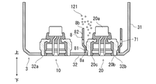
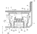
- FIG. 2 is a diagram for explaining a structure in the vicinity of the second ignition device 20 in the gas generator 100 according to the first embodiment.
- FIG. 2 shows a state before the operation of the second ignition device 20.
- the second ignition device 20 is fixed to the second fitting hole 32b formed in the bottom plate portion 32 of the lower shell 3.
- the second igniter 20 is formed of a second igniter 20a, a collar 20b attached to the housing 1 to support the second igniter 20a, and a resin material for fixing the second igniter 20a to the collar 20b.
- the holding portion 20c is provided.
- the second ignition device 20 is an example of an “ignition device”.
- the second igniter 20a has a metal cup body C2 containing an igniter and a pair of energizing pins EP2 and EP2 for receiving an electric current supply from the outside.
- the second igniter 20a is operated by the current supplied to the pair of energizing pins EP2 and EP2, the igniter is burned and the combustion product is discharged to the outside of the cup body C2.
- the collar 20b has a substantially tubular shape, and is fixed to the bottom plate portion 32 of the lower shell 3 by being welded to the bottom plate portion 32 with the lower end portion fitted in the second fitting hole 32b. .. As a result, the second igniter 20 is attached to the housing 1.
- the collar 20b does not have to be separate from the housing 1, and may be integrally molded with the housing (in this example, the lower shell 3 of the housing 1).
- the holding portion 20c is a resin member that fixes the second igniter 20a to the collar 20b by being interposed between the second igniter 20a and the collar 20b.
- the holding portion 20c covers the lower portion of the second igniter 20a and engages with the inner peripheral surface of the collar 20b so that at least a part of the cup body C2 is exposed from the holding portion 20c.
- the second igniter 20a is fixed to the igniter 20a.
- the entire cup body C2 may be overmolded by the holding portion 20c. That is, the entire cup body C2 may be covered with resin.
- the holding portion 20c is formed with a connector insertion space 20d into which a connector (not shown) for supplying power from an external power source can be inserted into the pair of energizing pins EP2 and EP2.
- the holding portion 20c covers and holds a part of the pair of energizing pins EP2 and EP2 so that the lower ends of the pair of energizing pins EP2 and EP2 are exposed in the connector insertion space 20d.
- the holding portion 20c maintains the insulating property between the pair of energizing pins EP2 and EP2.
- the container 7 is a second transmission which is an internal space of the container 7 together with the surrounding member 8 fixed in the housing 1 so as to surround the second ignition device 20 and the surrounding member 8 by being fitted with the surrounding member 8. It is formed including a lid member 9 that defines the fire chamber S2.
- the surrounding member 8 is formed in a tubular shape, and is arranged between the bottom plate portion 32 of the lower shell 3 and the dividing wall portion 41 of the partition wall member 4 so that the axial direction thereof coincides with the vertical direction of the gas generator 100. Has been done.
- One end of the surrounding member 8 is fixed in the housing 1 so as to surround the second ignition device 20.
- the surrounding member 8 has a press-fitting portion 81 including one end portion (lower end portion 8a) and an extending portion 82 including the other end portion (upper end portion 8b) and having an inner diameter larger than that of the press-fitting portion 81.
- the lower end portion 8a of the surrounding member 8 is in contact with the bottom plate portion 32 of the lower shell 3, and the collar 20b of the second ignition device 20 is press-fitted into the press-fitting portion 81.
- the extending portion 82 extends upward toward the dividing wall portion 41 of the partition wall member 4 without coming into contact with the second ignition device 20.
- the "axial direction” refers to the axial direction of the surrounding member 8 unless otherwise specified.
- the surrounding member 8 is surrounded so that the vertical position (that is, the position in the axial direction) of the upper end portion 8b of the surrounding member 8 is located within the vertical range of the cup body C2 of the second igniter 20a.
- the height of the member 8 is set.
- the upper end portion 8b of the surrounding member 8 may be located at a height equal to or higher than the upper end surface of the cup body C2. That is, the surrounding member 8 may extend to at least the range of the cup body C2 of the second igniter 20a in the axial direction. As a result, at least a part of the cup body C2 of the second igniter 20a is surrounded by the surrounding member 8.
- the lid member 9 is fitted with the surrounding member 8 so as to close the opening formed in the upper end portion 8b of the surrounding member 8. More specifically, the lid member 9 is formed at one end of the tubular fitting wall portion 91 that fits with the surrounding member 8 and the fitting wall portion 91, and closes the opening of the surrounding member 8. Part 92 and. In the container 7, the surrounding member 8 and the lid member 9 are fitted so that the outer peripheral surface of the extending portion 82 of the surrounding member 8 and the inner peripheral surface of the fitting wall portion 91 of the lid member 9 face each other. There is. That is, the fitting wall portion 91 is externally fitted to the surrounding member 8.
- the second firebox S2 is defined by being surrounded by the surrounding member 8 and the lid member 9.
- the second firebox S2 contains a second firebox 121 that is ignited by the operation of the second ignition device 20.
- the second explosive agent 121 is an example of a “combustible product”.
- a communication hole 71 for communicating the second firebox S2 and the external space of the container 7 is formed in the container 7, and the external space of the container 7 is formed so as to surround the container 7.
- the second gas generating agent 120 is arranged.
- the portion of the dot pattern indicated by reference numeral 72 in FIG. 2 indicates a portion (fitting portion) of the container 7 in which the surrounding member 8 and the lid member 9 are fitted. That is, the fitting portion 72 is a portion where the surrounding member 8 and the lid member 9 overlap each other. In the gas generator 100, the fitting portion 72 is a portion including a part of the extending portion 82 of the surrounding member 8 and a part of the fitting wall portion 91 of the lid member 9.
- the communication hole 71 is provided in the accommodating device 7 except for the fitting portion 72 in which the surrounding member 8 and the lid member 9 are fitted before the operation of the second ignition device 20. It is formed.
- a plurality of communication holes 71 are provided along the circumferential direction of the surrounding member 8 at a portion of the surrounding member 8 other than the fitting portion 72 that fits with the lid member 9 before the operation of the second ignition device 20. They are formed side by side at equal intervals. As the shape of the communication hole 71, various shapes such as a circle, an ellipse, and a rectangle can be selected.
- the communication hole 71 may be a slit formed at the end of the surrounding member 8 in addition to the through hole. Further, the communication hole 71 may be formed so as to exhibit a communication function at least when the second ignition device 20 is operated, and may be closed before the operation of the second ignition device 20.
- the communication hole 71 may be a hole that is closed by the sealing tape before the operation of the second ignition device 20 and the seal tape is cleaved by the combustion pressure when the second ignition device 20 is operated. Further, the communication hole 71 may be a fragile portion formed to be thinner than the other portion so that the communication hole 71 is preferentially cleaved over the other portion when a load due to the combustion pressure is applied.
- the closing portion 92 of the lid member 9 faces the divided wall portion 41 of the partition wall member 4.
- a protruding portion 921 protruding toward the dividing wall portion 41 is formed.
- the protruding portion 921 is received by a receiving portion 412 formed in the divided wall portion 41.
- a gap G1 is formed between the closed portion 92 and the divided wall portion 41.
- the distance D1 between the closing portion 92 and the dividing wall portion 41 is set so that the second gas generating agent 120 does not enter the gap G1.
- a gap G2 is also formed between the upper end surface of the cup body C2 of the second igniter 20a and the protruding portion 921.
- the second explosive agent 121 may be present in this gap G2.
- the gap G2 is filled with the second explosive agent 121 so as not to form an unnecessary space.
- the filter F1 has a tubular shape, the upper end portion thereof is supported by the top plate portion 22 of the upper shell 2, and the lower end portion is supported by the divided wall portion 41 of the partition wall member 4. In the state, it is arranged between the first gas generating agent 110 and the gas discharge hole 13.
- the filter F1 is configured to allow combustion gas to pass through, and the combustion gas generated in the first combustion chamber 11 and the second combustion chamber 12 is cooled by passing through the filter F1. At this time, the filter F1 filters the combustion gas by collecting the combustion residue of the combustion gas. Further, an annular gap 15 is formed between the filter F1 and the upper peripheral wall portion 21 in which the gas discharge hole 13 is formed.
- the first gas generating agent 110 and the second gas generating agent 120 a gas generating agent having a relatively low combustion temperature can be used.
- the combustion temperature of the first gas generating agent 110 and the second gas generating agent 120 can be set in the range of 1000 to 1700 ° C.
- known ones including, for example, guanidine nitrate (41% by weight), basic copper nitrate (49% by weight), a binder and additives are used.
- the first gas generating agent 110 and the second gas generating agent 120 may have various shapes such as granules, pellets, cylinders, and disks.
- the first explosive agent 111 and the second explosive agent 121 a gas generator having good ignitability and having a higher combustion temperature than the first gas generating agent 110 and the second gas generating agent 120 can be used.
- the combustion temperature of the first explosive agent 111 and the second explosive agent 121 can be set in the range of 1700 to 3000 ° C.
- known ones containing, for example, nitroguanidine (34% by weight) and strontium nitrate (56% by weight) can be used.
- the first explosive agent 111 and the second explosive agent 121 can adopt various shapes such as granules, pellets, cylinders, and disks.
- the gas generator 100 is configured so that the combustion gas of the second explosive agent 121 can be reliably discharged from the communication hole 71.
- the operation of the gas generator 100 will be mainly described with respect to the operation when the second ignition device 20 is operated and the second explosive charge 121 is burned.
- the case where the second igniter 20 operates later than the first igniter 10 (that is, after the first igniter 10 operates) will be described.
- the first ignition device 10 when the first ignition device 10 is activated, the first combustion charge 111 housed in the first transmission chamber S1 of the first combustion chamber 11 is burned, and the combustion gas is generated.
- the partition member 6 is burned and removed by the combustion gas of the first explosive agent 111, the combustion gas comes into contact with the first gas generating agent 110 and the first gas generating agent 110 is ignited.
- the first gas generating agent 110 burns, high-temperature and high-pressure combustion gas is generated in the first combustion chamber 11.
- this combustion gas passes through the filter F1, the combustion gas is cooled and the combustion residue is collected.
- the combustion gas of the first gas generating agent 110 cooled and filtered by the filter F1 passes through the gap 15, breaks the sealing tape 14, and is discharged from the gas discharge hole 13 to the outside of the housing 1.
- FIG. 3 is a diagram showing a case where the second ignition device 20 is operated in the gas generator 100 according to the first embodiment and the lid member 9 moves in a direction away from the surrounding member 8. In this case, the combustion pressure of the second explosive agent 121 acts on the lid member 9 in the axial direction upward, so that the lid member 9 moves upward along the axial direction.
- FIG. 3 shows a state in which the lid member 9 has moved until it comes into contact with the partition wall member 4.
- the combustion pressure of the second explosive agent 121 acts not only on the upper side in the axial direction but also on the outer side in the radial direction of the surrounding member 8. Therefore, for example, the surrounding member 8 and the lid member 9 may be deformed by the combustion pressure on the outer side in the radial direction, so that the movement of the lid member 9 in the direction away from the surrounding member 8 may be hindered.
- FIG. 4 is a diagram showing a case where the lid member 9 does not move in the direction away from the surrounding member 8 even when the second ignition device 20 is operated in the gas generator 100 according to the first embodiment.
- the second igniter 20 when the second igniter 20 operates and the lid member 9 moves in the direction away from the surrounding member 8 due to the combustion pressure of the second igniter 121, the second igniter 20 is fitted after the operation.
- the axial length L2 of the portion 72 is shorter than the axial length L1 (see FIG. 2) of the fitting portion 72 before the operation of the second ignition device 20. That is, the range of the fitting portion 72 after the operation of the second ignition device 20 is narrower than that before the operation of the second ignition device 20.
- the lid member 9 when the lid member 9 does not move in the direction away from the surrounding member 8 even when the second ignition device 20 operates, the axial direction of the fitting portion 72 after the second ignition device 20 operates.
- the length L3 of the second ignition device 20 is the same as the axial length L1 of the fitting portion 72 before the operation of the second ignition device 20. That is, the range of the fitting portion 72 after the operation of the second ignition device 20 does not change from that before the operation of the second ignition device 20. In this way, regardless of whether or not the lid member 9 moves in the direction away from the surrounding member 8 when the second ignition device 20 is operated, the range of the fitting portion 72 is the range before the operation of the second ignition device 20. Does not spread.
- a communication hole 71 is formed in a portion of the surrounding member 8 other than the fitting portion 72 that fits with the lid member 9 before the operation of the second ignition device 20. Therefore, the communication hole 71 is not closed by the lid member 9 before the operation of the second ignition device 20. Then, as described with reference to FIGS. 3 and 4, the range of the fitting portion 72 does not expand regardless of whether or not the lid member 9 moves in the direction away from the surrounding member 8, so that the communication hole 71 is formed. The lid member 9 does not block the second ignition device 20 during or after the operation. Further, of the surrounding member 8 and the lid member 9, a communication hole 71 is formed in the surrounding member 8 fixed in the housing 1.
- the lid member 9 is provided by fitting with the surrounding member 8, when the second ignition device 20 is operated, the lid member 9 moves in a direction away from the surrounding member 8 and is a component other than the surrounding member 8 (this In the example, the partition member 4) may come into contact (interference).
- the surrounding member 8 since the surrounding member 8 is fixed in the housing 1, even if the second ignition device 20 is operated, it does not come into contact with any part other than the lid member 9. Since the communication hole 71 is formed in such a surrounding member 8, when the second ignition device 20 is operated, the surrounding member 8 may come into contact with a part other than the lid member 9 to close the communication hole 71. Absent. As a result, as shown in FIGS.
- the combustion gas of the second propellant 121 generated in the second firebox S2 by the operation of the second ignition device 20 communicates without being hindered by the lid member 9. It is surely discharged to the external space of the container 7 through the hole 71. That is, it is avoided that the combustion gas is cut off.
- the communication hole 71 is closed by the sealing tape, the combustion gas is discharged by cleaving the sealing tape.
- the combustion gas of the second explosive agent 121 discharged from the communication hole 71 burns the second gas generating agent 120 arranged around the container 7, and a high-temperature and high-pressure combustion gas is generated in the second combustion chamber 12. Will be done.
- the combustion gas of the second gas generating agent 120 flows into the first combustion chamber 11 through the flow hole 55, is cooled and filtered by the filter F1, passes through the gap 15, and flows from the gas discharge hole 13 to the outside of the housing 1. It is released.
- the combustion gases of the first gas generating agent 110 and the second gas generating agent 120 flow into the airbag (not shown) after being discharged to the outside of the housing 1.
- the expansion of the airbag creates a cushion between the occupant and the rigid structure, protecting the occupant from impact.
- the amount of movement of the lid member 9 depends on the distance D1 between the closing portion 92 and the dividing wall portion 41 and the pressure of each combustion chamber. It is assumed depending on the degree of deformation of the housing 1.
- the gas generator 100 when the axial length L1 (see FIG. 2) of the fitting portion 72 before the operation of the second ignition device 20 is activated by the second ignition device 20. It is set to be longer than the amount of movement of the lid member 9 in the axial direction assumed in.
- the second ignition device 20 is activated and the lid member 9 moves in the direction away from the surrounding member 8, that is, even when the lid member 9 moves upward along the axial direction, the surrounding member 8 And the lid member 9 are maintained. That is, it is suppressed that the lid member 9 comes off from the surrounding member 8 and the combustion gas is discharged from the opening of the surrounding member 8. As a result, the combustion gas passes through the communication hole 71 more reliably, and the second explosive agent 121 is stably burned.
- FIG. 5 is a flowchart of a gas generator assembly method (hereinafter, simply referred to as “assembly method”) according to the first embodiment.
- assembly method simply referred to as “assembly method”.
- the first ignition device 10, the second ignition device 20, the upper shell 2, the lower shell 3, the partition wall member 4, the inner cylinder member 5, the partition member 6, and the surrounding members are enclosed.
- a member 8, a lid member 9, a filter F1, and a retainer R1 are prepared.
- the surrounding member 8 is formed with a communication hole 71, which is a through hole, in advance.
- the communication hole 71 is formed, for example, by drilling a tubular member as a base material.
- FIG. 6 is a diagram showing a state of the mounting process of the ignition device.
- each ignition device is inserted into the lower shell 3 through an opening formed at the upper end of the lower peripheral wall portion 31 of the lower shell 3.
- the first ignition device 10 is fixed to the lower shell 3 by being welded to the bottom plate portion 32 in a state of being fitted into the first fitting hole 32a.
- the second ignition device 20 is fixed to the lower shell 3 by being welded to the bottom plate portion 32 in a state of being fitted in the second fitting hole 32b. As a result, the second ignition device 20 is attached to the lower shell 3.
- FIG. 7 is a diagram showing a state of the mounting process of the surrounding member.
- the surrounding member 8 is inserted into the lower shell 3 through the opening formed at the upper end of the lower peripheral wall portion 31 of the lower shell 3.
- the collar 20b of the second ignition device 20 is press-fitted into the press-fitting portion 81 so that the lower end portion 8a of the surrounding member 8 comes into contact with the bottom plate portion 32 of the lower shell 3.
- the lower end portion 8a of the surrounding member 8 is fixed.
- FIG. 8 is a diagram showing a state of the filling process of the second explosive.
- the second explosive is filled inside the surrounding member 8 through the opening formed in the upper end portion 8b of the surrounding member 8.
- the second igniter 121 is filled between the second igniter 20 and the siege member 8. ..
- the second explosive charge 121 is not pressed against the second ignition device 20 (particularly, the cup body C2 protruding from the holding portion 20C), and the second explosive charge 121 is damaged. It is suppressed. Further, when the siege member 8 extends to a height of the cup body C2 or higher of the second ignition device 20, the second igniter 121 is less likely to spill from the inside of the siege member 8 when the second igniter is filled. As a result, the filling work can be easily performed.
- FIG. 9 is a diagram showing a state of the lid member attaching process
- FIG. 10 is a diagram showing a state in which the lid member is attached.
- the surrounding member 8 and the fitting wall portion 91 of the lid member 9 are fitted, so that the opening formed in the upper end portion 8b of the surrounding member 8 is a lid.
- the lid member 9 is attached so as to be closed by the closing portion 92 of the member 9.
- the container 7 is formed, and the second firebox S2, which is the internal space thereof, is defined.
- the surrounding member 8 and the lid member 9 are fitted so that the communication hole 71 is located at a portion other than the fitting portion 72 between the surrounding member 8 and the lid member 9. ..
- the communication hole 71 communicates the second fire chamber S2 with the external space of the container 7, and the combustion gas of the second explosive 121 is sent to the outside of the container 7. It can be discharged into the space.
- step S106 after fixing the inner cylinder member 5 so as to surround the first ignition device 10, the second gas generating agent 120 is filled inside the lower shell 3. After that, the partition member 4 is attached. At this time, the terminal portion 43 of the partition wall member 4 is arranged on the upper end surface of the lower peripheral wall portion 31 of the lower shell 3, and the fitting wall portion 42 of the partition wall member 4 is arranged so that the inner cylinder member 5 penetrates the through hole 411. The lower peripheral wall portion 31 of the lower shell 3 is fitted. After that, the inner cylinder member 5 is filled with the first explosive charge 111, and the partition member 6 is arranged on the first explosive charge 111.
- the filter F1 is arranged on the divided wall portion 41 of the partition wall member 4, the first gas generating agent 110 is filled inside the filter F1, and the retainer R1 is arranged on the first gas generating agent 110.
- the housing 1 is formed by fitting the lower peripheral wall portion 31 into the outer fitting wall portion 24 until the abutting portion 23 of the upper shell 2 abuts on the terminal portion 43 of the partition wall member 4.
- the contact portions of the upper shell 2 and the lower shell 3 are joined by a joining method (for example, welding or the like) suitable for moisture-proofing or the like of the gas generating agent filled inside.
- a joining method for example, welding or the like
- the portion of the accommodator 7 excluding the fitting portion 72 in which the surrounding member 8 and the lid member 9 are fitted before the operation of the second ignition device 20 is performed.
- a communication hole 71 is formed in the second fire chamber S2 to communicate with the external space of the container 7.
- a communication hole is formed in a fitting portion of the surrounding member with the lid member, and the communication hole is closed by the lid member before the operation of the ignition device, and the ignition device is used.
- the communication hole is opened. That is, it is premised that the lid member moves in the direction away from the surrounding member when the ignition device is activated.
- the surrounding member or the lid member is deformed due to the combustion pressure of the gas generating agent and the movement of the lid member is hindered, the communication blocked by the lid member is blocked.
- the holes may not open as desired. Then, there is a risk that the combustion performance becomes unstable and the parts are damaged due to the pressure increase.
- the portion other than the fitting portion 72 where the surrounding member 8 and the lid member 9 are fitted before the operation of the second ignition device 20 is performed in the surrounding member 8.
- the communication hole 71 is formed. That is, the communication hole 71 is formed so as to avoid the fitting portion 72 before the operation of the second ignition device 20. Then, the range of the fitting portion between the surrounding member 8 and the lid member 9 does not expand regardless of whether or not the lid member 9 moves in the direction away from the surrounding member 8. Therefore, in the gas generator 100, it is possible to prevent the communication hole 71 from being blocked by the lid member 9 regardless of whether or not the lid member moves away from the surrounding member when the second ignition device 20 is operated. it can.
- the surrounding member 8 and the lid member 9 by forming the communication hole 71 in the surrounding member 8 fixed in the housing 1, the surrounding member 8 becomes the lid member 9 when the second ignition device 20 is operated. It is also possible to prevent the communication hole 71 from being blocked by contacting a component other than the above. As a result, the gas generator 100 can reliably discharge the combustion gas of the second explosive agent 121 from the communication hole 71 to the external space of the accommodator 7. As a result, in the gas generator 100, desired combustion performance can be stably obtained, and damage to parts due to a pressure increase in the second firebox S2 can be suppressed.
- the length L1 in the axial direction of the fitting portion 72 before the operation of the second ignition device 20 is set, and the second ignition device 20 is operated to reduce the second explosive charge 121. It is set longer than the amount of movement of the lid member 9 with respect to the surrounding member 8 in the axial direction, which is assumed in the case of combustion. As a result, even when the second ignition device 20 is activated and the lid member 9 moves in a direction away from the surrounding member 8, the fitting between the surrounding member 8 and the lid member 9 is maintained. That is, it is possible to prevent the lid member 9 from coming off the surrounding member 8 and the combustion gas being discharged from the opening of the surrounding member 8. As a result, the combustion gas passes through the communication hole 71 more reliably, and the second explosive agent 121 burns stably. As a result, the combustion performance can be further stabilized.
- the second explosive agent 121 is filled inside the surrounding member 8 with the surrounding member 8 fixed so as to surround the second ignition device 20. If the second igniter 20 is to be pushed into the container filled with the second explosive 121 first, the closing portion 92 is turned down and the opening of the fitting wall portion 91 is turned up. It is necessary to fit the surrounding member 8 from above with the lid member 9 filled with the second explosive agent 121. For that purpose, it is necessary to temporarily invert the parts so that the state shown in FIG. 9 is inverted upside down, which complicates the assembly process. Further, there is a concern that the second explosive agent 121 is pressurized by the second ignition device 20 (cup body C2) and is damaged.
- the second ignition device 20 is arranged inside the surrounding member 8 and then the second explosive is filled. Therefore, it is not necessary to turn the parts upside down as described above, and the gas generator can be assembled in order from the bottom, and the assembly process can be simplified. Further, it is possible to prevent the second explosive charge 121 from being pressurized to the second ignition device 20 at the time of assembling the gas generator 100, and to suppress damage to the second explosive charge 121.
- the surrounding member 8 and the lid member 9 are fitted so that the communication hole 71 is located at a portion other than the fitting portion 72, so that the gas generator after completion has a second transmission. The combustion gas of the explosive 121 can be reliably discharged from the communication hole 71 to the external space of the container 7.
- FIG. 11 is a diagram for explaining a structure in the vicinity of the second ignition device 20 in the gas generator 100A according to the first modification of the first embodiment.
- FIG. 11 shows a state before the operation of the second ignition device 20.
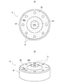
- 12A and 12B are views showing the lid member 9 according to the first modification of the first embodiment, FIG. 12A is a top view, and FIG. 12B is a perspective view.
- the gas generator 100A differs from the gas generator 100 in that a communication hole is formed in the lid member, and is generally different from the gas generator 100 in other respects. It is the same.
- a protruding portion 921 protruding toward the dividing wall portion 41 of the partition wall member 4 is formed in the center of the closing portion 92 of the lid member 9.
- the end surface portion 92a which is the top surface of the protruding portion 921, and the end surface portion 92a
- a concave concave surface portion 92b is formed on the outer surface of the closed portion 92 of the lid member 9 (the surface opposite to the surface defining the second firebox S2).
- the end surface portion 92a which is the top surface of the protruding portion 921
- the end surface portion 92a On the other hand, a concave concave surface portion 92b is formed.
- FIGS. 12A and 12B the range of the end face portion 92a and the range of the concave surface portion 92b are shown separately according to the difference in the dot pattern. As shown in FIGS.
- the concave surface portion 92b is formed in an annular shape so as to surround the end surface portion 92a, and is connected to the outer peripheral surface of the fitting wall portion 91.
- the concave surface portion 92b has a flow path FP1 formed between the closing portion 92 and the partition wall member 4 which is a member facing the closing portion 92 and connected to the space outside the container 7 in the radial direction of the surrounding member 8.
- the partition wall member 4 does not have the receiving portion 412 as shown in FIG. 2, and the divided wall portion 41 is formed substantially flat.
- a plurality of communication holes 71 are formed in the concave surface portion 92b so as to surround the end surface portion 91a so as to be arranged at equal intervals along the circumferential direction. That is, the communication hole 71 is a portion of the lid member 9 excluding the fitting portion 72 that fits with the surrounding member 8 before the operation of the second ignition device 20, and is formed in a portion recessed with respect to the end face portion 92a. Has been done.
- FIG. 13 is a diagram showing a case where the second ignition device 20 is operated in the gas generator 100A according to the first modification of the first embodiment and the lid member 9 moves in a direction away from the surrounding member 8.
- FIG. 13 shows a state in which the lid member 9 has moved until it comes into contact with the partition wall member 4.
- a communication hole 71 is formed in a portion of the lid member 9 other than the fitting portion 72 that fits with the surrounding member 8 before the operation of the second ignition device 20. Therefore, it is suppressed that the communication hole 71 is blocked by the surrounding member 8 regardless of whether or not the lid member 9 moves away from the surrounding member 8 when the second ignition device 20 is operated.
- the lid member 9 moves in a direction away from the surrounding member 8 due to the combustion pressure of the second explosive agent 121 when the second ignition device 20 is operated, the lid member 9 is a member facing the closing portion 92. It approaches a certain partition wall member 4. Then, as shown in FIG. 13, when the lid member 9 and the partition wall member 4 come into contact with each other, the end surface portion 92a of the closing portion 92 comes into contact with the dividing wall portion 41 of the partition wall member 4.
- the concave surface portion 92b in which the communication hole 71 is formed is recessed with respect to the end surface portion 92a, even when the closing portion 92 and the partition wall member 4 come into contact with each other, the concave surface portion 92b and the partition wall member 4 A flow path FP1 is secured between the two and the communication gas so that the combustion gas can flow. That is, it is also suppressed that the communication hole 71 is blocked by the partition wall member 4 when the second ignition device 20 is operated. As a result, as shown in FIG. 13, the combustion gas of the second explosive agent 121 generated in the second firebox S2 when the second ignition device 20 is activated is blocked by the surrounding member 8 and the partition wall member 4.
- the gas generator 100A when the communication hole 71 is formed in the closing portion 92 of the lid member 9, when the closing portion 92 comes into contact with the partition wall member 4 when the second ignition device 20 is operated. Even so, similarly to the gas generator 100, the combustion gas of the second explosive agent 121 can be reliably discharged from the communication hole 71 to the external space of the reservoir 7. As a result, desired combustion performance can be stably obtained, and damage to parts due to an increase in pressure can be suppressed.
- FIG. 14 is a diagram for explaining a structure in the vicinity of the second ignition device 20 in the gas generator 100B according to the second modification of the first embodiment.
- FIG. 14 shows a state before the operation of the second ignition device 20.
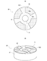
- 15A and 15B are views showing the lid member 9B according to the second modification of the first embodiment, FIG. 15A is a top view, and FIG. 15B is a perspective view.
- the gas generator 100B differs from the gas generator 100 in that a communication hole is formed in the inner wall of the groove formed in the lid member. However, it is almost the same in other respects.
- a groove 922 extending radially from the center of the closed portion 92 is formed on the outer surface of the closed portion 92 of the lid member 9B according to the second modification. ing.
- the groove 922 is connected to the space outside the container 7B in the radial direction of the surrounding member 8.
- a concave surface portion 92b which is the inner wall of the groove 922
- an end surface portion 92a which is the surface of the portion excluding the groove 922, are formed on the outer surface of the closed portion 92.
- the concave surface portion 92b is recessed with respect to the end surface portion 92a and is connected to the outer peripheral surface of the fitting wall portion 91.
- the concave surface portion 92b forms a flow path FP1 that connects the closing portion 92 and the partition wall member 4, which is a member facing the closing portion 92, with the space outside the container 7 in the radial direction of the surrounding member 8.
- a communication hole 71 is formed in the center of the concave surface portion 92b. That is, the communication hole 71 is a portion of the lid member 9B excluding the fitting portion 72 that fits with the surrounding member 8 before the operation of the second ignition device 20, and is formed in a portion recessed with respect to the end face portion 92a. Has been done.
- FIG. 16 is a diagram showing a case where the second ignition device 20 is operated in the gas generator 100B according to the first modification of the first embodiment and the lid member 9B moves in a direction away from the surrounding member 8.
- FIG. 15 shows a state in which the lid member 9B has moved until it comes into contact with the partition wall member 4.
- a communication hole 71 is formed in the lid member 9B except for the fitting portion 72 that fits with the surrounding member 8 before the operation of the second ignition device 20.
- the concave surface portion 92b in which the communication hole 71 is formed is recessed with respect to the end surface portion 92a.
- the end surface portion 92a of the closing portion 92 is in contact with the partition wall member 4, while the concave surface portion 92b and the partition wall member 4 are burned.
- the flow path FP1 is secured so that the gas can flow. That is, it is also suppressed that the communication hole 71 is blocked by the partition wall member 4 when the second ignition device 20 is operated.
- the combustion gas of the second explosive agent 121 generated in the second firebox S2 when the second ignition device 20 is activated is the surrounding member 8 and the partition wall. It is discharged to the external space of the container 7 through the communication hole 71 without being hindered by the member 4.
- the gas generator 100B also has the same effect as the gas generator 100A. That is, when the communication hole 71 is formed in the closing portion 92 of the lid member 9B, even if the closing portion 92 comes into contact with the partition wall member 4 when the second ignition device 20 is operated, the second explosive agent 121 The combustion gas of the above can be reliably discharged from the communication hole 71 to the external space of the container 7. As a result, desired combustion performance can be stably obtained, and damage to parts due to an increase in pressure can be suppressed.
- FIG. 17 is a diagram for explaining a structure in the vicinity of the second ignition device 20 in the gas generator 100C according to the third modification of the first embodiment.
- FIG. 17 shows a state before the operation of the second ignition device 20.
- the gas generator 100C is different from the gas generator 100 in that the fitting wall portion of the lid member is fitted in the surrounding member, and is substantially the same in other respects. More specifically, in the container 7 according to the third modification, the surrounding surface of the extending portion 82 of the surrounding member 8 and the inner peripheral surface of the fitting wall portion 91 of the lid member 9C face each other with the surrounding member 8.
- the container 7 is formed by fitting with the lid member 9. Even in such a gas generator 100C, the same effect as that of the gas generator 100 is obtained.
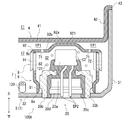
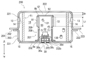
- FIG. 18 is an axial sectional view of the gas generator 200 according to the second embodiment.
- the gas generator 200 in the gas generator 200, one combustion chamber 16 and one ignition device 30 are housed in a housing 201 formed by welding and fixing an upper shell 202 and a lower shell 203.
- the gas generator 200 includes an ignition device 30, an accommodator 207, a filter F1, and a housing 201 accommodating them.
- the gas generator 200 according to the second embodiment will be described focusing on the differences from the gas generator 100, and detailed description will be omitted by assigning the same reference numerals to the same configurations as the gas generator 100. To do.
- Both ends of the housing 201 are closed in the axial direction by joining the metal upper shell 202 and the lower shell 203, each of which is formed in a substantially cylindrical shape with a bottom, with their open ends facing each other. It is formed in a short cylindrical shape.
- the upper shell 202 has a tubular upper peripheral wall portion 221 and a top plate portion 222 that closes the upper end of the upper peripheral wall portion 221, and forms an internal space by these.
- An opening of the upper shell 202 is formed by the lower end of the upper peripheral wall portion 221.
- a joint portion 223 extending outward in the radial direction is connected to the lower end portion of the upper peripheral wall portion 221.
- the lower shell 203 has a tubular lower peripheral wall portion 231 and a bottom plate portion 232 that closes the lower end of the lower peripheral wall portion 231, thereby forming an internal space. Further, the bottom plate portion 232 is formed with a fitting hole 232b to which the ignition device 30 is fixed. A joint portion 233 extending outward in the radial direction is connected to the upper end portion of the lower peripheral wall portion 231.
- the joint portion 223 of the upper shell 202 and the joint portion 233 of the lower shell 203 are overlapped and joined by laser welding or the like to form a short cylindrical housing 201 in which both ends in the axial direction are closed. Further, a plurality of gas discharge holes 13 closed by the sealing tape 14 are formed side by side in the circumferential direction on the upper peripheral wall portion 221 of the upper shell 202.
- the ignition device 30 is arranged at a substantially central position in the internal space of the housing 201 and is fixed to the fitting hole 232b of the lower shell 203.
- the ignition device 30 has the same configuration as the second ignition device 20 described in the first embodiment. That is, the ignition device 30 includes an igniter 30a, a collar 30b attached to the housing 201 to support the igniter 30a, and a holding portion 30c made of a resin material for fixing the igniter 30a to the collar 30b. , Equipped with. A connector insertion space 30d into which a connector (not shown) can be inserted is formed in the holding portion 30c.
- the ignition device 30 is an example of an “ignition device”.
- the accommodating device 207 accommodating the ignition device 30 has the same configuration as the accommodating device 7 described in the first embodiment. That is, the housing 207 is a fire transmission room which is an internal space of the housing 207 together with the surrounding member 208 by fitting the surrounding member 208 fixed in the housing 201 so as to surround the ignition device 30 and the surrounding member 208. It is formed including a lid member 209 that defines S3.
- the surrounding member 208 is formed in a tubular shape, and is arranged between the bottom plate portion 232 of the lower shell 203 and the top plate portion 222 of the upper shell 202 so that the axial direction thereof coincides with the vertical direction of the gas generator 100. Has been done.
- the lower end portion 8a of the surrounding member 208 is fixed in the housing 201 so as to surround the ignition device 30.
- the lower end portion 8a of the surrounding member 208 is in contact with the bottom plate portion 232 of the lower shell 203, and the collar 30b of the ignition device 30 is press-fitted into the surrounding member 208.
- the lid member 209 is fitted with the surrounding member 208 so as to close the opening formed in the upper end portion 8b of the surrounding member 208.
- the lid member 209 includes a tubular fitting wall portion 91 that fits with the surrounding member 208, and a closing portion 92 that is formed at one end of the fitting wall portion 91 and closes the opening of the surrounding member 208. .. In the container 207, the fitting wall portion 91 is fitted to the surrounding member 208.
- the firebox S3 is defined by being surrounded by the surrounding member 208 and the lid member 209.
- the firebox S3 contains a firebox 131 that is ignited by the operation of the ignition device 30.
- the accommodator 207 is formed with a communication hole 71 that communicates the fire transmission room S3 with the external space of the accommodator 207.
- the gas generating agent 130 is arranged so as to surround the container 207, and the filter F1 is arranged so as to surround the gas generating agent 130.
- a communication hole 71 is formed to communicate the chamber S3 with the external space of the container 207. More specifically, the communication hole 71 is formed in a portion of the surrounding member 208 other than the fitting portion 72 that fits with the lid member 209 before the ignition device 30 is operated.
- the closing portion 92 of the lid member 209 faces the top plate portion 222 of the upper shell 202, and a gap G1 is formed between the closing portion 92 and the top plate portion 222. There is. The distance D1 between the closing portion 92 and the top plate portion 222 is set so that the gas generating agent 130 does not enter the gap G1.
- a retainer or cushion may be arranged in the gap G1.
- FIG. 19 is a diagram showing a case where the ignition device 30 is operated in the gas generator 200 according to the second embodiment and the lid member 209 moves in a direction away from the surrounding member 208. As shown in FIG. 19, the lid member 209 moves upward along the axial direction due to the combustion pressure of the gunpowder 131. In the gas generator 200, a communication hole 71 is formed in a portion of the lid member 209 other than the fitting portion 72 that fits with the surrounding member 208 before the ignition device 30 is operated.
- the communication hole 71 is suppressed from being blocked by the surrounding member 208 regardless of whether or not the lid member 209 moves away from the surrounding member 208 when the ignition device 30 is operated. Further, of the surrounding member 208 and the lid member 209, since the communication hole 71 is formed in the surrounding member 208 fixed in the housing 201, the surrounding member 208 is other than the lid member 209 when the ignition device 30 is operated. It is also suppressed that the communication hole 71 is blocked by contacting the parts of the above. As a result, the gas generator 200 can reliably discharge the combustion gas of the fire transmission room S3 from the communication hole 71 to the external space of the accommodator 207. As a result, desired combustion performance can be stably obtained, and damage to parts due to an increase in pressure can be suppressed.
- the combustion gas of the gunpowder 131 discharged from the communication hole 71 burns the gas generating agent 130 arranged around the container 207, and high-temperature and high-pressure combustion gas is generated in the combustion chamber 16. After being cooled and filtered by the filter F1, the combustion gas of the gas generating agent 130 passes through the gap 15, breaks the sealing tape 14, and is discharged from the gas discharge hole 13 to the outside of the housing 201.
- the axial length L1 of the fitting portion 72 before the operation of the ignition device 30 is the ignition device 30. Is set longer than the amount of movement of the lid member 209 with respect to the surrounding member 208 in the axial direction, which is assumed when As a result, even when the ignition device 30 is activated and the lid member 209 moves in a direction away from the surrounding member 208, the fitting between the surrounding member 208 and the lid member 209 is maintained, and the lid member 209 is moved from the surrounding member 209. It is possible to suppress deviation from 208. As a result, the combustion gas passes through the communication hole 71 more reliably, and the combustion performance can be more stabilized.
- the method of assembling the gas generator according to the first embodiment can be adopted. That is, in filling the explosive charge 131, the explosive charge 131 is filled inside the encircling member 208 with the surrounding member 208 fixed so as to surround the ignition device 30. Since the igniter 131 is filled after arranging the igniter 30 inside the surrounding member 208, it is possible to prevent the igniter 131 from being pressurized to the igniter 30 when assembling the gas generator 200, and the explosive 131 is damaged. Can be suppressed.
- FIG. 20 is a diagram for explaining a structure in the vicinity of the ignition device 30 in the gas generator 200D according to the modified example of the second embodiment.
- FIG. 20 shows the state of the ignition device 30 before operation.
- the gas generator 200D differs from the gas generator 200 in that a communication hole is formed in the lid member, and is substantially the same in other respects.
- a protruding portion 921 protruding toward the top plate portion 222 of the upper shell 202 is formed in the center of the closing portion 92 of the lid member 209D according to the modified example.
- an end surface portion 92a which is the top surface of the protruding portion 921
- a concave surface portion 92b recessed with respect to the end surface portion 92a are formed on the outer surface of the closing portion 92 of the lid member 209D.
- the concave surface portion 92b is formed in an annular shape so as to surround the end surface portion 92a, and is connected to the outer peripheral surface of the fitting wall portion 91.
- the concave surface portion 92b is formed with a flow path FP1 that connects the closing portion 92 and the upper shell 202, which is a member facing the closed portion 92, with the space outside the container 207 in the radial direction of the surrounding member 208.
- a plurality of communication holes 71 are formed in the concave surface portion 92b so as to surround the end surface portion 91a so as to be arranged at equal intervals along the circumferential direction. That is, the communication hole 71 is a portion of the lid member 209D excluding the fitting portion 72 that fits with the surrounding member 8 before the operation of the second ignition device 20, and is formed in a portion recessed with respect to the end face portion 92a. Has been done.
- the communication hole 71 is formed in the lid member 209D except for the fitting portion 72, the communication hole 71 is a surrounding member when the second ignition device 20 is operated. Blockage by 208 is suppressed. Further, the concave surface portion 92b in which the communication hole 71 is formed is recessed with respect to the end surface portion 92a. Therefore, even when the closed portion 92 and the upper shell 202 (more specifically, the top plate portion 222) come into contact with each other, the combustion gas can flow between the concave portion 92b and the upper shell 202. Road FP1 is secured. That is, it is suppressed that the communication hole 71 is blocked by the upper shell 202 when the ignition device 30 is operated.
- the combustion gas of the gunpowder 131 generated in the firebox S3 by the operation of the ignition device 30 passes through the communication hole 71 and enters the external space of the container 207 without being hindered by the surrounding member 208 or the upper shell 202. It is discharged.
- the gas generator 200D even when the communication hole 71 is formed in the closing portion 92 of the lid member 209D and the closing portion 92 comes into contact with the upper shell 202 due to the operation of the ignition device 30.
- the combustion gas of the explosive agent 131 can be reliably discharged from the communication hole 71 to the external space of the container 207. As a result, desired combustion performance can be stably obtained, and damage to parts due to an increase in pressure can be suppressed.
- the explosive for burning the gas generating agent is shown as an example of the "combustible material", but in the technique of the present disclosure, the ignition device burns the gas generating agent without using the explosive. It can also be applied to type gas generators. In that case, the gas generating agent corresponds to the "combustion”.
- the "combustion product” is not limited to the combustion gas generated by the combustion of the gas generating agent or the explosive, and may be a flame.
- the bottom plate portions 32 and 332 and the collars 20b and 30b are separately fixed by welding or the like is shown, but those in which these are integrally formed in advance can also be used. ..
- the form and arrangement of the communication holes are not limited to the above-described embodiments, and known techniques can be used.
- the communication hole may be localized so that the flame of the propellant is preferentially supplied to the region of the external space of the container where the gas generating agent is arranged in a large amount.
Landscapes
- Physics & Mathematics (AREA)
- Fluid Mechanics (AREA)
- Engineering & Computer Science (AREA)
- Mechanical Engineering (AREA)
- Air Bags (AREA)
Applications Claiming Priority (2)
| Application Number | Priority Date | Filing Date | Title |
|---|---|---|---|
| JP2019-189651 | 2019-10-16 | ||
| JP2019189651A JP7343354B2 (ja) | 2019-10-16 | 2019-10-16 | ガス発生器、及びガス発生器の組立方法 |
Publications (1)
| Publication Number | Publication Date |
|---|---|
| WO2021075376A1 true WO2021075376A1 (ja) | 2021-04-22 |
Family
ID=75487351
Family Applications (1)
| Application Number | Title | Priority Date | Filing Date |
|---|---|---|---|
| PCT/JP2020/038318 Ceased WO2021075376A1 (ja) | 2019-10-16 | 2020-10-09 | ガス発生器、及びガス発生器の組立方法 |
Country Status (2)
| Country | Link |
|---|---|
| JP (1) | JP7343354B2 (https=) |
| WO (1) | WO2021075376A1 (https=) |
Cited By (3)
| Publication number | Priority date | Publication date | Assignee | Title |
|---|---|---|---|---|
| US11485313B2 (en) * | 2020-06-23 | 2022-11-01 | Autoliv Asp, Inc. | Inflator for a passive vehicle safety device |
| US20250076010A1 (en) * | 2021-11-30 | 2025-03-06 | Daicel Corporation | Gas generator |
| US20250091544A1 (en) * | 2022-06-06 | 2025-03-20 | Daicel Corporation | Gas generator |
Families Citing this family (2)
| Publication number | Priority date | Publication date | Assignee | Title |
|---|---|---|---|---|
| JP6946097B2 (ja) * | 2017-07-21 | 2021-10-06 | 株式会社ダイセル | ガス発生器 |
| CN115782806B (zh) | 2022-11-25 | 2026-01-06 | 延锋汽车智能安全系统有限责任公司 | 点火系统及其制造方法、气体发生器和安全气囊 |
Citations (6)
| Publication number | Priority date | Publication date | Assignee | Title |
|---|---|---|---|---|
| JPH07164998A (ja) * | 1993-12-13 | 1995-06-27 | Sensor Technol Kk | ガス発生器及びエアバッグモジュール |
| JP2006160253A (ja) * | 2004-12-08 | 2006-06-22 | Delphi Technologies Inc | 気体発生器 |
| US7374204B2 (en) * | 2005-11-28 | 2008-05-20 | Autoliv Asp, Inc. | Inflator second stage combustion control |
| JP2013226889A (ja) * | 2012-04-25 | 2013-11-07 | Daicel Corp | ガス発生器 |
| JP2016034768A (ja) * | 2014-08-01 | 2016-03-17 | 株式会社ダイセル | ガス発生器 |
| CN109927664A (zh) * | 2019-04-04 | 2019-06-25 | 湖北航鹏化学动力科技有限责任公司 | 一种双级式气体发生器 |
-
2019
- 2019-10-16 JP JP2019189651A patent/JP7343354B2/ja active Active
-
2020
- 2020-10-09 WO PCT/JP2020/038318 patent/WO2021075376A1/ja not_active Ceased
Patent Citations (6)
| Publication number | Priority date | Publication date | Assignee | Title |
|---|---|---|---|---|
| JPH07164998A (ja) * | 1993-12-13 | 1995-06-27 | Sensor Technol Kk | ガス発生器及びエアバッグモジュール |
| JP2006160253A (ja) * | 2004-12-08 | 2006-06-22 | Delphi Technologies Inc | 気体発生器 |
| US7374204B2 (en) * | 2005-11-28 | 2008-05-20 | Autoliv Asp, Inc. | Inflator second stage combustion control |
| JP2013226889A (ja) * | 2012-04-25 | 2013-11-07 | Daicel Corp | ガス発生器 |
| JP2016034768A (ja) * | 2014-08-01 | 2016-03-17 | 株式会社ダイセル | ガス発生器 |
| CN109927664A (zh) * | 2019-04-04 | 2019-06-25 | 湖北航鹏化学动力科技有限责任公司 | 一种双级式气体发生器 |
Cited By (4)
| Publication number | Priority date | Publication date | Assignee | Title |
|---|---|---|---|---|
| US11485313B2 (en) * | 2020-06-23 | 2022-11-01 | Autoliv Asp, Inc. | Inflator for a passive vehicle safety device |
| US20250076010A1 (en) * | 2021-11-30 | 2025-03-06 | Daicel Corporation | Gas generator |
| US12595991B2 (en) * | 2021-11-30 | 2026-04-07 | Daicel Corporation | Gas generator |
| US20250091544A1 (en) * | 2022-06-06 | 2025-03-20 | Daicel Corporation | Gas generator |
Also Published As
| Publication number | Publication date |
|---|---|
| JP7343354B2 (ja) | 2023-09-12 |
| JP2021062814A (ja) | 2021-04-22 |
Similar Documents
| Publication | Publication Date | Title |
|---|---|---|
| WO2021075376A1 (ja) | ガス発生器、及びガス発生器の組立方法 | |
| US10953842B2 (en) | Gas generator | |
| EP2531381B1 (en) | Gas generator and assembling method of the same | |
| JP7449432B2 (ja) | ガス発生器 | |
| US10870409B2 (en) | Gas generator | |
| EP1731384B1 (en) | Gas generator | |
| JP6888228B2 (ja) | ガス発生器 | |
| JP5021447B2 (ja) | ガス発生器 | |
| WO2021054117A1 (ja) | 点火器組立体及び点火器組立体の組立方法 | |
| JP7410714B2 (ja) | ガス発生器 | |
| JP2020059484A (ja) | ガス発生器 | |
| WO2019230503A1 (ja) | ガス発生器 | |
| JP2021030814A (ja) | ガス発生器、及びガス発生器の製造方法 | |
| JP2021014217A (ja) | ガス発生器 | |
| WO2021261134A1 (ja) | ガス発生器 | |
| JP7805856B2 (ja) | 点火装置、及び、ガス発生器 | |
| JP7369044B2 (ja) | ガス発生器 | |
| JP7527102B2 (ja) | ガス発生器の組立方法 | |
| JP7368325B2 (ja) | ガス発生器 | |
| JP2006001778A (ja) | ガス発生剤及びこれを有するガス発生器 | |
| JP2004098980A (ja) | ガス発生器 | |
| WO2018220950A1 (ja) | ガス発生器、及びデュアルタイプのガス発生器の組立方法 | |
| JP2021006446A (ja) | ガス発生器 | |
| JP2019182102A (ja) | ガス発生器 |
Legal Events
| Date | Code | Title | Description |
|---|---|---|---|
| 121 | Ep: the epo has been informed by wipo that ep was designated in this application |
Ref document number: 20875800 Country of ref document: EP Kind code of ref document: A1 |
|
| NENP | Non-entry into the national phase |
Ref country code: DE |
|
| 122 | Ep: pct application non-entry in european phase |
Ref document number: 20875800 Country of ref document: EP Kind code of ref document: A1 |