WO2021066112A1 - 電池セルケースおよびそれを用いた電池の製造方法 - Google Patents
電池セルケースおよびそれを用いた電池の製造方法 Download PDFInfo
- Publication number
- WO2021066112A1 WO2021066112A1 PCT/JP2020/037469 JP2020037469W WO2021066112A1 WO 2021066112 A1 WO2021066112 A1 WO 2021066112A1 JP 2020037469 W JP2020037469 W JP 2020037469W WO 2021066112 A1 WO2021066112 A1 WO 2021066112A1
- Authority
- WO
- WIPO (PCT)
- Prior art keywords
- opening
- container lid
- battery cell
- resin
- cell case
- Prior art date
Links
Images


Classifications
-
- H—ELECTRICITY
- H01—ELECTRIC ELEMENTS
- H01M—PROCESSES OR MEANS, e.g. BATTERIES, FOR THE DIRECT CONVERSION OF CHEMICAL ENERGY INTO ELECTRICAL ENERGY
- H01M50/00—Constructional details or processes of manufacture of the non-active parts of electrochemical cells other than fuel cells, e.g. hybrid cells
- H01M50/10—Primary casings, jackets or wrappings of a single cell or a single battery
- H01M50/102—Primary casings, jackets or wrappings of a single cell or a single battery characterised by their shape or physical structure
- H01M50/103—Primary casings, jackets or wrappings of a single cell or a single battery characterised by their shape or physical structure prismatic or rectangular
-
- H—ELECTRICITY
- H01—ELECTRIC ELEMENTS
- H01M—PROCESSES OR MEANS, e.g. BATTERIES, FOR THE DIRECT CONVERSION OF CHEMICAL ENERGY INTO ELECTRICAL ENERGY
- H01M50/00—Constructional details or processes of manufacture of the non-active parts of electrochemical cells other than fuel cells, e.g. hybrid cells
- H01M50/60—Arrangements or processes for filling or topping-up with liquids; Arrangements or processes for draining liquids from casings
- H01M50/609—Arrangements or processes for filling with liquid, e.g. electrolytes
- H01M50/627—Filling ports
- H01M50/636—Closing or sealing filling ports, e.g. using lids
-
- H—ELECTRICITY
- H01—ELECTRIC ELEMENTS
- H01M—PROCESSES OR MEANS, e.g. BATTERIES, FOR THE DIRECT CONVERSION OF CHEMICAL ENERGY INTO ELECTRICAL ENERGY
- H01M10/00—Secondary cells; Manufacture thereof
- H01M10/05—Accumulators with non-aqueous electrolyte
- H01M10/058—Construction or manufacture
- H01M10/0587—Construction or manufacture of accumulators having only wound construction elements, i.e. wound positive electrodes, wound negative electrodes and wound separators
-
- H—ELECTRICITY
- H01—ELECTRIC ELEMENTS
- H01M—PROCESSES OR MEANS, e.g. BATTERIES, FOR THE DIRECT CONVERSION OF CHEMICAL ENERGY INTO ELECTRICAL ENERGY
- H01M50/00—Constructional details or processes of manufacture of the non-active parts of electrochemical cells other than fuel cells, e.g. hybrid cells
- H01M50/10—Primary casings, jackets or wrappings of a single cell or a single battery
- H01M50/116—Primary casings, jackets or wrappings of a single cell or a single battery characterised by the material
- H01M50/117—Inorganic material
- H01M50/119—Metals
-
- H—ELECTRICITY
- H01—ELECTRIC ELEMENTS
- H01M—PROCESSES OR MEANS, e.g. BATTERIES, FOR THE DIRECT CONVERSION OF CHEMICAL ENERGY INTO ELECTRICAL ENERGY
- H01M50/00—Constructional details or processes of manufacture of the non-active parts of electrochemical cells other than fuel cells, e.g. hybrid cells
- H01M50/10—Primary casings, jackets or wrappings of a single cell or a single battery
- H01M50/116—Primary casings, jackets or wrappings of a single cell or a single battery characterised by the material
- H01M50/121—Organic material
-
- H—ELECTRICITY
- H01—ELECTRIC ELEMENTS
- H01M—PROCESSES OR MEANS, e.g. BATTERIES, FOR THE DIRECT CONVERSION OF CHEMICAL ENERGY INTO ELECTRICAL ENERGY
- H01M50/00—Constructional details or processes of manufacture of the non-active parts of electrochemical cells other than fuel cells, e.g. hybrid cells
- H01M50/10—Primary casings, jackets or wrappings of a single cell or a single battery
- H01M50/116—Primary casings, jackets or wrappings of a single cell or a single battery characterised by the material
- H01M50/124—Primary casings, jackets or wrappings of a single cell or a single battery characterised by the material having a layered structure
- H01M50/1243—Primary casings, jackets or wrappings of a single cell or a single battery characterised by the material having a layered structure characterised by the internal coating on the casing
-
- H—ELECTRICITY
- H01—ELECTRIC ELEMENTS
- H01M—PROCESSES OR MEANS, e.g. BATTERIES, FOR THE DIRECT CONVERSION OF CHEMICAL ENERGY INTO ELECTRICAL ENERGY
- H01M50/00—Constructional details or processes of manufacture of the non-active parts of electrochemical cells other than fuel cells, e.g. hybrid cells
- H01M50/10—Primary casings, jackets or wrappings of a single cell or a single battery
- H01M50/116—Primary casings, jackets or wrappings of a single cell or a single battery characterised by the material
- H01M50/124—Primary casings, jackets or wrappings of a single cell or a single battery characterised by the material having a layered structure
- H01M50/1245—Primary casings, jackets or wrappings of a single cell or a single battery characterised by the material having a layered structure characterised by the external coating on the casing
-
- H—ELECTRICITY
- H01—ELECTRIC ELEMENTS
- H01M—PROCESSES OR MEANS, e.g. BATTERIES, FOR THE DIRECT CONVERSION OF CHEMICAL ENERGY INTO ELECTRICAL ENERGY
- H01M50/00—Constructional details or processes of manufacture of the non-active parts of electrochemical cells other than fuel cells, e.g. hybrid cells
- H01M50/10—Primary casings, jackets or wrappings of a single cell or a single battery
- H01M50/147—Lids or covers
- H01M50/148—Lids or covers characterised by their shape
- H01M50/15—Lids or covers characterised by their shape for prismatic or rectangular cells
-
- H—ELECTRICITY
- H01—ELECTRIC ELEMENTS
- H01M—PROCESSES OR MEANS, e.g. BATTERIES, FOR THE DIRECT CONVERSION OF CHEMICAL ENERGY INTO ELECTRICAL ENERGY
- H01M50/00—Constructional details or processes of manufacture of the non-active parts of electrochemical cells other than fuel cells, e.g. hybrid cells
- H01M50/10—Primary casings, jackets or wrappings of a single cell or a single battery
- H01M50/147—Lids or covers
- H01M50/155—Lids or covers characterised by the material
- H01M50/157—Inorganic material
- H01M50/159—Metals
-
- H—ELECTRICITY
- H01—ELECTRIC ELEMENTS
- H01M—PROCESSES OR MEANS, e.g. BATTERIES, FOR THE DIRECT CONVERSION OF CHEMICAL ENERGY INTO ELECTRICAL ENERGY
- H01M50/00—Constructional details or processes of manufacture of the non-active parts of electrochemical cells other than fuel cells, e.g. hybrid cells
- H01M50/10—Primary casings, jackets or wrappings of a single cell or a single battery
- H01M50/147—Lids or covers
- H01M50/155—Lids or covers characterised by the material
- H01M50/16—Organic material
-
- H—ELECTRICITY
- H01—ELECTRIC ELEMENTS
- H01M—PROCESSES OR MEANS, e.g. BATTERIES, FOR THE DIRECT CONVERSION OF CHEMICAL ENERGY INTO ELECTRICAL ENERGY
- H01M50/00—Constructional details or processes of manufacture of the non-active parts of electrochemical cells other than fuel cells, e.g. hybrid cells
- H01M50/10—Primary casings, jackets or wrappings of a single cell or a single battery
- H01M50/147—Lids or covers
- H01M50/166—Lids or covers characterised by the methods of assembling casings with lids
- H01M50/167—Lids or covers characterised by the methods of assembling casings with lids by crimping
-
- H—ELECTRICITY
- H01—ELECTRIC ELEMENTS
- H01M—PROCESSES OR MEANS, e.g. BATTERIES, FOR THE DIRECT CONVERSION OF CHEMICAL ENERGY INTO ELECTRICAL ENERGY
- H01M50/00—Constructional details or processes of manufacture of the non-active parts of electrochemical cells other than fuel cells, e.g. hybrid cells
- H01M50/10—Primary casings, jackets or wrappings of a single cell or a single battery
- H01M50/147—Lids or covers
- H01M50/166—Lids or covers characterised by the methods of assembling casings with lids
- H01M50/169—Lids or covers characterised by the methods of assembling casings with lids by welding, brazing or soldering
-
- H—ELECTRICITY
- H01—ELECTRIC ELEMENTS
- H01M—PROCESSES OR MEANS, e.g. BATTERIES, FOR THE DIRECT CONVERSION OF CHEMICAL ENERGY INTO ELECTRICAL ENERGY
- H01M50/00—Constructional details or processes of manufacture of the non-active parts of electrochemical cells other than fuel cells, e.g. hybrid cells
- H01M50/10—Primary casings, jackets or wrappings of a single cell or a single battery
- H01M50/172—Arrangements of electric connectors penetrating the casing
- H01M50/174—Arrangements of electric connectors penetrating the casing adapted for the shape of the cells
- H01M50/176—Arrangements of electric connectors penetrating the casing adapted for the shape of the cells for prismatic or rectangular cells
-
- H—ELECTRICITY
- H01—ELECTRIC ELEMENTS
- H01M—PROCESSES OR MEANS, e.g. BATTERIES, FOR THE DIRECT CONVERSION OF CHEMICAL ENERGY INTO ELECTRICAL ENERGY
- H01M50/00—Constructional details or processes of manufacture of the non-active parts of electrochemical cells other than fuel cells, e.g. hybrid cells
- H01M50/30—Arrangements for facilitating escape of gases
-
- H—ELECTRICITY
- H01—ELECTRIC ELEMENTS
- H01M—PROCESSES OR MEANS, e.g. BATTERIES, FOR THE DIRECT CONVERSION OF CHEMICAL ENERGY INTO ELECTRICAL ENERGY
- H01M50/00—Constructional details or processes of manufacture of the non-active parts of electrochemical cells other than fuel cells, e.g. hybrid cells
- H01M50/50—Current conducting connections for cells or batteries
- H01M50/543—Terminals
- H01M50/545—Terminals formed by the casing of the cells
-
- H—ELECTRICITY
- H01—ELECTRIC ELEMENTS
- H01M—PROCESSES OR MEANS, e.g. BATTERIES, FOR THE DIRECT CONVERSION OF CHEMICAL ENERGY INTO ELECTRICAL ENERGY
- H01M50/00—Constructional details or processes of manufacture of the non-active parts of electrochemical cells other than fuel cells, e.g. hybrid cells
- H01M50/50—Current conducting connections for cells or batteries
- H01M50/543—Terminals
- H01M50/547—Terminals characterised by the disposition of the terminals on the cells
- H01M50/55—Terminals characterised by the disposition of the terminals on the cells on the same side of the cell
-
- H—ELECTRICITY
- H01—ELECTRIC ELEMENTS
- H01M—PROCESSES OR MEANS, e.g. BATTERIES, FOR THE DIRECT CONVERSION OF CHEMICAL ENERGY INTO ELECTRICAL ENERGY
- H01M50/00—Constructional details or processes of manufacture of the non-active parts of electrochemical cells other than fuel cells, e.g. hybrid cells
- H01M50/60—Arrangements or processes for filling or topping-up with liquids; Arrangements or processes for draining liquids from casings
-
- Y—GENERAL TAGGING OF NEW TECHNOLOGICAL DEVELOPMENTS; GENERAL TAGGING OF CROSS-SECTIONAL TECHNOLOGIES SPANNING OVER SEVERAL SECTIONS OF THE IPC; TECHNICAL SUBJECTS COVERED BY FORMER USPC CROSS-REFERENCE ART COLLECTIONS [XRACs] AND DIGESTS
- Y02—TECHNOLOGIES OR APPLICATIONS FOR MITIGATION OR ADAPTATION AGAINST CLIMATE CHANGE
- Y02E—REDUCTION OF GREENHOUSE GAS [GHG] EMISSIONS, RELATED TO ENERGY GENERATION, TRANSMISSION OR DISTRIBUTION
- Y02E60/00—Enabling technologies; Technologies with a potential or indirect contribution to GHG emissions mitigation
- Y02E60/10—Energy storage using batteries
Definitions
- the present invention relates to a battery cell case composed of a container body and a container lid, and in particular, the container lid has an opening for gas release generated by injection of an electrolytic solution or pre-charging / discharging, and the container.
- the present invention relates to a battery cell case in which the periphery of the opening on the outer surface of the lid is not resin-laminated, and a method for manufacturing a battery using the battery cell case.
- a square container is composed of a lid and a container, the material of which is mainly stainless steel or aluminum, and the lid and the container are assembled by laser welding.
- the material is expensive and the productivity of laser welding is low because it takes time, it is expected to replace it with a cheaper material and apply a more productive lid assembly method.
- laminated steel sheets obtained by laminating a film mainly composed of polyethylene (PE) or polypropylene (PP) on chrome-plated steel sheets are widely used as inexpensive container materials for containers such as foods and chemicals.
- a container made of such a laminated steel plate can be stored for a long period of time by suppressing deterioration of various contents by selecting a film suitable for the contents, and the container can be stored in a short time by wrapping the container lid. It can be assembled to the main body and can have even higher strength. Furthermore, if higher airtightness is required, the container lid can be attached to the container body by welding. However, until now, it has not been widely used as a material for battery containers, except in special cases. The reason is considered to be the sealing property of the opening.
- the electrolytic solution is injected through the opening, and the electrolytic solution is permeated into the battery container before precharging and discharging. After releasing the gas generated at that time to the outside of the container, the opening is often sealed. Sealing is often performed by welding, but the laminated steel sheet is laminated with resin, and it is difficult to close the holes (that is, openings) of the laminated steel sheet by welding. Therefore, the laminated steel sheet has not been widely used as a material for a battery container so far.
- Japanese Unexamined Patent Publication No. 2011-258501 Japanese Unexamined Patent Publication No. 2012-018866 Japanese Unexamined Patent Publication No. 2012-094374 Japanese Unexamined Patent Publication No. 2012-064337
- Patent Document 1 discloses a method for manufacturing a battery cell case formed by laminating two laminated steel sheets, which is a step of preparing two laminated steel sheets and superimposing the fused surfaces on each other. The process includes a step of applying heat to the fused portions while bending the periphery of the fused portions to heat-seal the fused portions with each other. According to this method, it is taught that the fusion property between two laminated steel sheets can be improved because the fused portions are not peeled off by bending.
- Patent Document 1 does not describe or suggest an opening for injecting an electrolytic solution.
- Patent Document 2 discloses a method for manufacturing a battery cell case and a battery cell case aiming at improving the fusion (heat seal) strength between laminated steel sheets.
- the case is formed by superimposing the flange portions of a pair of laminated steel plates having a drawing portion, and each flange portion has ribs, and these ribs are engaged and heat-sealed. It is taught that the heat seal strength is improved.
- Patent Document 2 does not describe or suggest an opening for injecting an electrolytic solution.
- Patent Document 3 discloses an exterior material (container) for a battery made of a laminated steel plate, and a method for manufacturing the exterior material.
- a stepped portion matching the cross-sectional shape of the tab is formed in advance on the exterior material (laminated steel plate) so that tabs (drawing terminals for positive and negative electrodes) can be pulled out from the inside of the exterior material. It is taught that this makes it possible to avoid the formation of a gap between the exterior material and the tab, and to ensure the tightness of the battery case more reliably.
- Patent Document 3 does not describe or suggest an opening for injecting an electrolytic solution.
- Patent Document 4 relates to a sealed storage battery.
- the storage battery includes a metallic outer body having a flange portion and a metal plate (which corresponds to a laminated steel plate) fused to one surface of the flange portion via a resin film.
- the metal plate protrudes to the outside of the flange portion, and the protruding portion is folded back to the other surface of the flange portion and fused via the resin film.
- Patent Document 4 discloses that the exterior body is sealed with a metal plate after injecting the electrolytic solution into the exterior body, but neither describes nor suggests that the metal plate has an opening. ..
- the present invention provides a battery cell case in which the outer surface of the container lid having an opening is not resin-laminated around the opening, and a method for manufacturing a battery using the same.
- the purpose is to provide.
- the opening can be easily sealed by welding, and the container lid can be at least a part of the positive electrode or negative electrode terminal.
- the present invention provides the following aspects.
- a battery cell case in which the container body and the container lid are joined by winding or welding.
- the container body is made of a steel plate whose inner surface is resin-laminated.
- the resin laminate is composed of a film containing a polyolefin resin as a main component.
- the container lid is made of a metal plate The container lid has an opening for gas release generated by injection of an electrolytic solution or pre-charging / discharging.
- a battery cell case characterized in that, on the outer surface of the container lid, a resin laminate is not formed in a range of at least 2 mm from the periphery of the opening.
- the steel plate of the container body is subjected to a plating treatment containing at least one of Al, Cr, Ni, Sn, Zn, and Zr and / or a chemical conversion treatment containing at least one of Si, V, Ti, Zr, P, and Cr.
- the base material is a surface-treated steel sheet that has been subjected to
- the battery cell case according to [1], wherein the metal plate of the container lid is made of any one of a Ni-plated steel plate, a stainless steel plate, and an aluminum plate as a base material.
- the metal plate of the container lid is made of either a Ni-plated steel plate or a stainless steel plate as a base material.
- the metal plate of the container lid is made of either a stainless steel plate or an aluminum plate as a base material.
- a battery cell case in which the periphery of the opening is not resin-laminated on the outer surface of the container lid having the opening, and a method for manufacturing a battery using the same.
- the opening can be easily welded and the container lid can be at least part of the positive or negative electrode terminal.
- FIG. 1 is a schematic view of a battery cell case (container lid is non-polar), which is one aspect of the present invention.
- FIG. 2 is a schematic view of a battery cell case (a container lid is electrically connected to a positive electrode terminal), which is one aspect of the present invention.
- FIG. 3 is a schematic view of a battery cell case (a container lid is electrically connected to a negative electrode terminal), which is one aspect of the present invention.
- FIG. 4 is a schematic view of a battery cell case, which is one aspect of the reference invention.
- FIG. 5 is an enlarged schematic view of the opening of FIG. 4 before and after sealing.
- FIGS. 1 to 3 show a schematic view of a battery cell case, which is one aspect of the present invention.
- the battery cell case is configured by joining the container body and the container lid by welding or caulking. In order to reduce waste of material, it is preferable to join the container body and the end portions of the container lid.
- the container body is composed of a resin-laminated steel plate on the inner surface thereof (that is, the inner surface when the battery cell case is used).
- the steel sheet used as the base material of the resin-laminated steel sheet may be appropriately selected as long as it does not cause problems in plating property, weldability, and adhesion to the resin laminate.
- the type of steel sheet may be selected so that appropriate corrosion resistance can be obtained according to the electrolytic solution of the battery, the usage environment, and the like. Since corrosion resistance and container strength can be ensured depending on the thickness of the steel sheet, a steel sheet having good cost performance may be used.
- As the steel sheet in addition to stainless steel, pure iron, carbon steel, low alloy steel, zirconium, vanadium, aluminum, aluminum iron alloy, zinc-copper alloy and the like may be adopted. The thickness of the steel sheet can be appropriately selected.
- the thickness of the steel sheet may be 0.05 mm or more, preferably 0.1 mm or more, 1.2 mm or less, preferably 1.0 mm or less. This is because if it is too thin, sufficient strength as a battery cell case may not be obtained, and if it is too thick, workability is lowered and cost is increased.
- the steel plate may be a plated steel plate.
- the type of plating may be selected so as to obtain appropriate corrosion resistance according to the electrolytic solution of the battery, the usage environment, etc., as long as the adhesion to the resin laminate is not affected.
- the plating may contain one or more kinds of elements from Al, Cr, Ni, Sn, Zn, and Zr. Plating containing these elements can be obtained by a conventional method. In plating containing a plurality of elements, the plating element may be plated in one or more of an alloy layer, a layered state, and a partially granular partial layered state.
- tinfree steel having a chromium oxide layer and a metallic chromium layer, a nickel layer, or a nickel layer and a nickel-iron alloy layer
- It may be nickel plating such that it has, or tin plating that has a tin layer or a tin layer and a tin-iron alloy layer.
- the amount of plating may be appropriately selected depending on the electrolytic solution of the battery, the usage environment, and the like so as to obtain appropriate corrosion resistance, and may be in the range of 5 mg / m 2 to 5 g / m 2.
- the plating method may be thermal spraying, thin-film deposition, or hot-dip galvanizing.
- the steel sheet may be subjected to a known chemical conversion treatment.
- the chemical conversion treatment in this case is not particularly limited, and a known treatment can be applied, and may be a silica-based chemical conversion treatment, a chromate-based chemical conversion treatment, or the like.
- a silane coupling agent may be used, and in the case of an inorganic chemical conversion treatment film layer, one or two selected from silica fine particles, vanadium compounds, titanium compounds, zirconium compounds, phosphoric acid compounds, chromium oxides and the like.
- the above is exemplified.
- the chromium oxide may contain chromium of any valence, and may contain, for example, trivalent chromium and / or hexavalent chromium.
- the silane coupling agent is not particularly limited, and an appropriate silane coupling agent may be selected in consideration of adhesion to the resin to be laminated.
- an appropriate silane coupling agent may be selected in consideration of adhesion to the resin to be laminated.
- vinyltrimethoxysilane, vinyltriethoxysilane, etc. ⁇ -Aminopropyltrimethoxysilane, ⁇ -aminopropylethoxysilane, N- [2- (vinylbenzylamino) ethyl] -3-aminopropyltrimethoxysilane, ⁇ -methacryloxypropylmethyldimethoxysilane, ⁇ -methacryloxypropyl Trimethoxysilane, ⁇ -methacryloxypropylmethyldiethoxysilane, ⁇ -methacryloxypropyltriethoxysilane, ⁇ -glycidoxypropyltriethoxysilane, ⁇ -glycidoxypropyl
- silica fine particles There are two types of silica fine particles, liquid phase silica and vapor phase silica, but either of these may be used.
- the vanadium compound include, but are not limited to, ammonium vanadate, ammonium metavanadate, and the like.
- titanium compound examples include Ti alkoxide, basic Ti carbonate, Ti fluoride, Ti-containing organic chelate, and Ti-containing coupling agent (Ti alkoxide contains an organic functional group such as an epoxy group, a vinyl group, an amino group, or a methacryloxy group. (Bound compound) and the like can be exemplified, but the present invention is not limited thereto.
- zirconium compound examples include, but are not limited to, Zr alkoxide, basic Zr carbonate, Zr fluoride, and Zr-containing organic chelate.
- Examples of the phosphoric acid compound include, but are not limited to, orthophosphoric acid, pyrophosphoric acid, and polyphosphoric acid.
- various chromate treatments such as electrolytic chromate and resin chromate, and other chromate-free chemical conversion treatments may be performed.
- the steel sheet is tin-free steel that has already been subjected to a chromium-containing surface treatment, the adhesiveness, processing adhesion, and electrolytic solution resistance of the resin laminate to the steel sheet are as good as those of the metal surface that has undergone various chromate treatments. Is.
- the amount of adhesion of the chemical conversion coating layer is 20 mg / m for the chemical conversion coating layer below the outermost layer, that is, for the chemical conversion coating layer used for the front surface, in order to ensure good adhesion and corrosion resistance. It may be 2 or more and 1000 mg / m 2 or less. If the amount of adhesion is excessively small, the chemical conversion treatment film may not be sufficiently present on the surface of the steel sheet, and the adhesion to the resin laminate may not be sufficient. On the other hand, if the amount of adhesion is excessively large, the chemical conversion coating itself may be coagulated and broken, and the cost is high.
- a scale removal treatment may be performed as a base treatment.
- the scale removing treatment method include pickling, sandblasting, and grid blasting. After pickling and sandblasting, a base treatment using a combination of chromate treatment or chromate-free treatment, strike plating treatment, and epoxy primer treatment is preferable from the viewpoint of strengthening the chemical adhesion between the laminated resin and the steel sheet.
- the chemical conversion treatment layer can contain various rust preventives, pigments, inorganic compounds, and organic compounds.
- the method for forming the chemical conversion treatment layer is not particularly limited, and known methods such as coating and baking can be applied without limitation.
- the steel plate of the container body may be a surface-treated steel plate that has been treated to contain at least one of Cr, Si, and Zr.
- the steel sheet subjected to these treatments is preferable because it has excellent adhesion to the polyolefin-based resin laminate.
- the resin-laminated steel plate is a resin-laminated steel plate that is the base material.
- the resin laminate on the inner surface of the container body is composed of a film containing a polyolefin resin as a main component. Since the polyolefin-based resin has electrolytic solution resistance, it is suitable as an inner surface resin of a battery cell case, and can also serve as a resin for fusion (heat sealing) at a winding portion with a container lid or the like.
- the polyolefin-based resin is a resin having the following repeating unit (formula 1).
- the resin having the repeating unit of (Equation 1) constitutes 50% by mass or more.
- -CR 1 H-CR 2 R 3- (Equation 1) (In Formula 1, R 1 and R 2 each independently represent an alkyl group or hydrogen having 1 to 12 carbon atoms, and R 3 represents an alkyl group, aryl group or hydrogen having 1 to 12 carbon atoms).
- the polyolefin-based resin may be a homopolymer of the above-mentioned structural unit or a copolymer of two or more types. It is preferable that 5 or more repeating units are chemically bonded. If the number is less than 5, it may be difficult to exert the polymer effect (for example, flexibility, extensibility, etc.).
- repeating unit examples include terminal olefins such as ethylene, propene (propylene), 1-butene, 1-pentene, 4-methyl-1-pentene, 1-hexene, 1-octene, 1-decene and 1-dodecene.
- terminal olefins such as ethylene, propene (propylene), 1-butene, 1-pentene, 4-methyl-1-pentene, 1-hexene, 1-octene, 1-decene and 1-dodecene.
- aliphatic olefins such as the repeating unit that appears when addition polymerization and the repeating unit when isobutene is added, and styrene monomer, o-methylstyrene, m-methylstyrene, p-methylstyrene, o-ethylstyrene, m.
- -Alkylated styrene such as ethyl styrene, o-ethyl styrene, ot-butyl styrene, mt-butyl styrene, pt-butyl styrene, halogenated styrene such as monochlorostyrene, styrene-based such as terminal methyl styrene.
- aromatic olefins such as monomer-added polymer units.
- repeating unit homopolymers examples include low-density polyethylene, medium-density polyethylene, high-density polyethylene, linear low-density polyethylene, crosslinked polyethylene, polypropylene, polybutene, polypentene, which are homopolymers of terminal olefins. Examples thereof include polyhexene, polyoctenylene, polyisoprene, polybutadiene and the like.
- an ethylene-propylene copolymer an ethylene-butene copolymer, an ethylene-propylene-hexadiene copolymer, an ethylene-propylene-5-ethylidene-2-norvonene copolymer
- examples thereof include aliphatic polyolefins such as, and aromatic polyolefins such as styrene-based copolymers, but the present invention is not limited to these, and the above repeating unit may be satisfied. Further, it may be a block copolymer or a random copolymer. Moreover, you may use these resins individually or in mixture of 2 or more types.
- the polyolefin used in the present invention may contain the above-mentioned olefin unit as a main component, and vinyl monomer, polar vinyl monomer, and diene monomer, which are substitutions of the above-mentioned unit, are copolymerized in a monomer unit or a resin unit. You may.
- the copolymer composition is 50% by mass or less, preferably 30% by mass or less, based on the olefin unit. If it exceeds 50% by mass, the properties of the olefin resin such as the barrier property against the corrosion-causing substance may deteriorate.
- polar vinyl monomer examples include acrylic acid derivatives such as acrylic acid, methyl acrylate and ethyl acrylate, methacrylic acid derivatives such as methacrylic acid, methyl methacrylate and ethyl methacrylate, acrylonitrile, maleic anhydride and maleic anhydride.
- acrylic acid derivatives such as acrylic acid, methyl acrylate and ethyl acrylate
- methacrylic acid derivatives such as methacrylic acid, methyl methacrylate and ethyl methacrylate
- acrylonitrile maleic anhydride and maleic anhydride.
- Imid derivatives, vinyl chloride and the like can be mentioned.
- the most preferable from the viewpoint of handleability and barrier property of corrosion-causing substances are low-density polyethylene, medium-density polyethylene, high-density polyethylene, linear low-density polyethylene, crosslinked polyethylene, polypropylene, or a mixture of two or more of these.
- a film containing polyethylene or polypropylene as a main component is more suitable from the viewpoints of cost, distribution, ease of fusion, and the like.
- the resin containing a polyolefin-based resin as a main component means a resin containing 50% by mass or more of the polyolefin-based resin, and in addition to the pure resin of the polyolefin-based resin, the total amount is less than 50% by mass, and the polyolefin-based resin is used. It can contain a resin other than the resin. Further, an acid-modified polyolefin may be used in order to improve the adhesion to the plated steel sheet.
- the polyolefin-based resin as the main component may be 50% by mass or more. More preferably, the polyolefin-based resin is 70% by mass or more, 90% by mass or more, and the polyolefin-based resin itself.
- the polymerized material preferably has a lower decomposition temperature than that of the polyolefin-based resin alone.
- the container lid is composed of a metal plate.
- the metal plate may be appropriately selected as long as it does not cause a problem in the weldability of the container lid, and for example, a Ni-plated steel plate, an aluminum plate, a stainless steel plate, a tinfree steel (TFS) plate or the like may be adopted. .. Further, the metal plate may be plated or chemical-converted in the same manner as the resin-laminated steel sheet described above in order to improve performance such as corrosion resistance.
- the resin laminate is not applied in a range of at least 2 mm from the periphery of the opening described later. This is because the opening of the container lid, which will be described later, is sealed by welding. If a resin laminate is present at or near the welded portion, welding defects may occur due to evaporation of the resin or the like. Since the resin laminate is not present in a range of at least 2 mm from the periphery of the opening to be the welded portion, welding defects due to the resin laminate are suppressed. The wider the range where the resin is not laminated, the less adverse effect it has on the welded part, which is preferable.
- the non-resin-laminated portion on the outer surface of the container lid can be energized, the non-laminated portion resists the battery electrode, that is, at least a part of the positive electrode or negative electrode terminal, or the opening. It can be used as an energizing contact when welding.
- the resin laminate may not be applied in an appropriate range on the outer surface of the container lid.
- the resin laminate since the resin laminate is useful for improving the corrosion resistance, the resin laminate may be applied to an appropriate range excluding the periphery of the opening to obtain an appropriate corrosion resistance according to the usage environment of the battery and the like.
- the same material as the resin laminate of the steel plate of the container body may be used, or a film containing a polyolefin resin as a main component may be used.
- the method of welding the opening is not particularly limited, but workability and safety are taken into consideration when the electrolytic solution is injected into the battery cell case and the size of the opening to be welded is taken into consideration. In this respect, resistance welding is preferable.
- a container lid having a non-resin-laminated portion on at least a part of the outer surface that is, a container lid capable of energizing between the non-laminated portion and the opening to be the welded portion, is suitable for resistance welding.
- a resin laminate may be applied to the inner surface of the container lid. As a result, appropriate corrosion resistance can be obtained depending on the electrolytic solution of the battery, the usage environment, and the like. Further, it can also serve as a resin for fusion (heat sealing) at a winding portion and the like with the container body.
- the resin laminate the same material as the resin laminate of the steel plate of the container body described above may be used, or a film containing a polyolefin resin as a main component may be used.
- the container lid has an opening (liquid injection port) for discharging the gas generated by the injection of the electrolytic solution and the pre-charging / discharging.
- an opening liquid injection port
- the opening may be sealed after the completion of liquid injection or pre-charging / discharging. This is to prevent leakage of the electrolytic solution from the opening and invasion of water from the outside through the opening.
- the sealing of the opening may be performed by welding, for example resistance welding.
- the upper limit of the diameter of the opening may be 10 mm or less, preferably 5 mm or less, and more preferably 2 mm or less.
- the container lid may have terminal holes for positive electrode terminals and / or negative electrode terminals in addition to the above-mentioned opening (liquid injection port). As a result, the electric connection between the positive electrode and the negative electrode inside the battery can be obtained, and the battery energy can be used outside the battery.
- FIG. 1 is a schematic view of a battery cell case provided with terminal holes for positive electrode terminals and negative electrode terminals.
- the metal plate of the container lid is made of either a stainless steel plate or an aluminum plate as a base material.
- the container lid may have a terminal hole for a negative electrode terminal in addition to the opening (liquid injection port).
- FIG. 2 schematically illustrates this aspect.
- the negative electrode inside the battery can be electrically connected to the outside via a terminal hole for the negative electrode terminal.
- the positive electrode inside the battery can be electrically connected to the outside via the battery lid.
- the container lid has the same potential as the positive electrode, but since the metal plate constituting the container lid is either a stainless steel plate or an aluminum plate, an electrolytic solution, particularly a non-aqueous electrolytic solution used in a lithium ion battery or the like, No metal dissolution occurs in.
- a normal container lid requires two terminal holes (one for a positive electrode and one for a negative electrode), but the container lid in this embodiment only needs to have one terminal hole. Since the terminal holes can serve as a path for moisture to permeate into the battery, the smaller the number of terminal holes, the more the invasion of moisture into the battery can be suppressed, and the deterioration of battery performance can be suppressed, which is preferable.
- the metal plate of the container lid is made of either stainless steel plate or Ni-plated steel plate as the base material.
- the container lid may have a terminal hole for a positive electrode terminal in addition to the opening (liquid injection port).
- FIG. 3 schematically illustrates this aspect.
- the positive electrode inside the battery can be electrically connected to the outside via a terminal hole for the positive electrode terminal.
- the negative electrode inside the battery can be electrically connected to the outside via the battery lid.
- the container lid has the same potential as the negative electrode, but since the metal plate constituting the container lid is either a stainless steel plate or a Ni-plated steel plate, an electrolytic solution, particularly a non-aqueous electrolytic solution used in a lithium ion battery or the like.
- a normal container lid requires two terminal holes (one for a positive electrode and one for a negative electrode), but the container lid in this embodiment only needs to have one terminal hole. Since the terminal holes can serve as a path for moisture to permeate into the battery, the smaller the number of terminal holes, the more the invasion of moisture into the battery can be suppressed, and the deterioration of battery performance can be suppressed, which is preferable.
- the metal material that can be used for the container lid can be appropriately selected from the viewpoint of solubility in the electrolytic solution, depending on whether it is non-polar, negative electrode connection, or positive electrode connection.
- Ni-plated steel plate, stainless steel plate, aluminum plate, and TFS are used as the metal material of the non-polar container lid. It is possible, and Ni-plated steel plate and stainless steel can be used for the container lid connected to the negative electrode, and stainless steel plate and aluminum plate can be used for the container lid connected to the positive electrode.
- the container lid is made non-polar, any of Ni-plated steel plate, stainless steel plate, aluminum plate, and TFS plate can be used, but since two holes will be made for the positive electrode and negative electrode, it is necessary to seal them. costly. On the other hand, in the case of the negative electrode connection and the positive electrode connection, since the lid also serves as one terminal, only one hole for the electrode is sufficient, and the cost for sealing the electrode is not required.
- the caulking of the container lid and the container body is inwardly wound. Is preferable. This is because if the winding (caulking) portion is externally wound, it becomes a protruding portion of the battery cell case, and the possibility of a short circuit with the outside increases.
- the battery cell case is constructed by joining the container body and the container lid by welding or caulking. In the schematic views of FIGS. 1 to 3, they are joined by caulking. In order to reduce waste of material, it is preferable to join the container body and the end portions of the container lid.
- the container body and the container lid are each resin-laminated, the resin laminates can be fused (heat-sealed) to improve the airtightness of the container.
- the steel plates may be welded to each other after removing or evaporating the laminated resin so as not to cause welding defects. The method described in the specification of No. 107770 may be used.
- the shape and size of the battery cell case can be appropriately selected according to the application and the like.
- the battery cell case may have a square shape, a cylindrical shape, or the like. Compared to the cylindrical type, the square type has excellent heat dissipation, so that it is easy to increase in size, is excellent in economy, and has good loadability, which is preferable.
- the large battery cell case is not particularly defined by a standard or the like, but may have at least one side of 120 mm or more and further 148 mm or more.
- the manufacturing method may include the following steps. Insert the battery element into the container body; The container body and the container lid are joined by winding or welding; Inject electrolyte through the opening; By pre-charging and discharging, the water content in the electrolytic solution is decomposed and gasified to release the water content from the battery cell case; It is sealed by welding a metal lid to the opening.
- each step will be described.
- the above-mentioned container body is used for the container body, and the battery element is inserted into the container body.
- the battery element may be a laminate of a positive electrode, a negative electrode, and a separator.
- the container body and the container lid are joined by winding or welding.
- joining by caulking is schematically shown.
- the container body and the container lid are each resin-laminated, the resin laminates can be fused (heat-sealed) to improve the airtightness of the container.
- the steel plates may be welded to each other after removing or evaporating the laminated resin so as not to cause welding defects.
- the method described in the specification of No. 107770 may be used.
- the electrolytic solution is not particularly limited as the electrolyte, but is obtained by dissolving the supporting salt in a solvent such as an organic solvent, an ionic liquid which is itself in a liquid state, and further dissolving the supporting salt in the ionic liquid.
- a solvent such as an organic solvent, an ionic liquid which is itself in a liquid state, and further dissolving the supporting salt in the ionic liquid.
- the organic solvent an organic solvent usually used for an electrolytic solution of a lithium secondary battery can be exemplified.
- carbonates, halogenated hydrocarbons, ethers, ketones, nitriles, lactones, oxolane compounds and the like can be used.
- propylene carbonate, ethylene carbonate, 1,2-dimethoxyethane, dimethyl carbonate, diethyl carbonate, ethylmethyl carbonate and the like and a mixed solvent thereof are suitable.
- organic solvents given as examples, in particular, using one or more non-aqueous solvents selected from the group consisting of carbonates and ethers in terms of solubility, dielectric constant and viscosity, and stability of the supporting salt. It is preferable because it is excellent and the charge / discharge efficiency of the battery is high.
- the ionic liquid is not particularly limited as long as it is an ionic liquid usually used as an electrolytic solution for a lithium secondary battery.
- an ionic liquid usually used as an electrolytic solution for a lithium secondary battery.
- the cation component of the ionic liquid or N- methyl -N- propyl piperidinium, dimethylethyl methoxy ammonium cation and the like, and an anionic component, BF 4 -, N (SO 2 CF 3) 2 - And so on.
- the supporting salt used in the electrolyte is not particularly limited.
- SO 2 ) (C 4 F 9 SO 2 ) LiCF 3 SO 3 derivative, LiN (CF 3 SO 2 ) 2 derivative and LiC (CF 3 SO 2 ) 3 derivative. It is preferable to use a salt from the viewpoint of electrical characteristics.
- the water content in the electrolytic solution is decomposed and gasified by pre-charging / discharging, and the water content is released from the battery cell case. If the battery cell case is sealed with the water in the electrolytic solution remaining, the water is then gasified and the internal pressure of the battery cell case rises, leading to damage to the battery cell case, and the water in the electrolytic solution becomes the battery element. It may adversely affect the battery performance.
- the temperature of the electrolytic solution is raised by precharging / discharging to decompose and gasify the water content in the electrolytic solution and release it from the battery cell case through the opening of the container lid.
- the battery cell case is sealed by welding a metal lid to the opening.
- the material of the lid is not particularly limited as long as it is a metal that can be welded, and it is preferable that the material is the same as the material of the container lid from the viewpoint of weldability.
- the battery cell case can be sealed by welding the opening of the container lid (the injection port of the electrolytic solution). In other words, since the battery can be sealed immediately after pre-charging and discharging, the possibility of moisture entering the battery cell case and causing contamination can be dramatically reduced, and the battery performance can be improved. It can greatly contribute to maintenance.
- the reference invention relates to a battery cell case composed of a container body and a container lid, and in particular, the container body and the container lid are each composed of a steel plate laminated with a resin, and an electrolytic solution is injected or precharged / discharged. It relates to a battery cell case in which the opening for gas release generated by the battery is sealed by an opening seal made of a metal foil laminated with a resin.
- a square container is composed of a lid and a container, the material of which is mainly stainless steel or aluminum, and the lid and the container are assembled by laser welding.
- the material is expensive and the productivity of laser welding is low because it takes time, it is expected to replace it with a cheaper material and apply a more productive lid assembly method.
- laminated steel sheets obtained by laminating a film mainly made of polyethylene or polypropylene on chrome-plated steel sheets are widely used as inexpensive container materials for containers such as foods and chemicals.
- a container made of such a laminated steel plate can be stored for a long period of time by suppressing deterioration of various contents by selecting a film suitable for the contents, and the container can be stored in a short time by winding the container lid. It can be assembled to the main body and can have even higher strength. Furthermore, if higher airtightness is required, the container lid can be attached to the container body by welding. However, until now, it has not been widely used as a material for battery containers, except in special cases. It is considered that it is due to the sealing property of the opening.
- Patent Document 1 Japanese Patent Application Laid-Open No. 2011-258501
- Patent Document 2 Japanese Patent Application Laid-Open No. 2012-018866
- Patent Document 3 Japanese Patent Application Laid-Open No. 2012-094374 [Summary of Reference Invention] [Problems to be solved by the reference invention]
- Patent Document 1 discloses a method for manufacturing a battery cell case formed by laminating two laminated steel sheets, which is a step of preparing two laminated steel sheets and superimposing the fused surfaces on each other. The process includes a step of applying heat to the fused portions while bending the periphery of the fused portions to heat-seal the fused portions with each other. According to this method, it is taught that the fusion property between two laminated steel sheets can be improved because the fused portions are not peeled off by bending.
- Patent Document 1 does not describe or suggest an opening for injecting an electrolytic solution.
- Patent Document 2 discloses a method for manufacturing a battery cell case and a battery cell case aiming at improving the heat seal strength between laminated steel sheets.
- the case is formed by superimposing the flange portions of a pair of laminated steel plates having a drawing portion, and each flange portion has ribs, and these ribs are engaged and heat-sealed. It is taught that the heat seal strength is improved.
- Patent Document 2 does not describe or suggest an opening for injecting an electrolytic solution.
- Patent Document 3 discloses an exterior material (container) for a battery made of a laminated steel plate, and a method for manufacturing the exterior material.
- a stepped portion matching the cross-sectional shape of the tab is formed in advance on the exterior material (laminated steel plate) so that the tab (drawing terminal of the positive electrode and the negative electrode) can be pulled out from the inside of the exterior material. It is taught that this makes it possible to avoid the formation of a gap between the exterior material and the tab, and to ensure the tightness of the battery case more reliably.
- Patent Document 3 does not describe or suggest an opening for injecting an electrolytic solution.
- an object of the reference invention is to provide a battery cell case capable of sealing an opening of a container lid made of a laminated steel plate with an opening seal made of a laminated metal foil by a novel configuration.
- the container body and the container lid are each made of a steel plate laminated with resin.
- the resin on the inner surface of the container body and the inner and outer surfaces of the container lid is made of a film containing a polyolefin resin as a main component.
- the container lid has an opening for gas release generated by injection of an electrolytic solution or pre-charging / discharging.
- the opening seal is made of resin-laminated metal leaf.
- the resin on the surface of the opening seal in contact with the container lid is made of a film containing a polyolefin resin as a main component.
- a battery cell case characterized in that the opening seal is fixed to the container lid and the opening is sealed through a fusion portion between the film of the opening seal and the film of the container lid.
- the steel plate of at least one or both of the container body and the container lid is plated and / or Si, V, Ti, Zr, P containing at least one of Al, Cr, Ni, Sn, Zn, and Zr.
- the area of the opening is 0.19 mm 2 or more and 25 mm 2 or less, and wherein the shortest distance from the end of the opening to the end portion of the fusion part is more than 5 mm, it is 15mm or less,
- the container lid has terminal holes for positive electrode terminals and negative electrode terminals in addition to the opening.
- a battery cell case in which an opening of a container lid made of a laminated steel plate can be sealed by an opening seal made of a laminated metal foil.
- FIG. 4 is a schematic view of a battery cell case, which is one aspect of the reference invention.
- FIG. 5 is an enlarged schematic view of the opening of FIG. 4 before and after sealing. [Mode for carrying out the invention]
- FIG. 4 shows a schematic diagram of a battery cell case, which is one aspect of the reference invention.
- the battery cell case is configured by joining the container body and the container lid by welding or caulking. In order to reduce waste of material, it is preferable to join the container body and the end portions of the container lid.
- the container body and the container lid are each made of a steel plate laminated with resin.
- the steel sheet used as the base material of the resin-laminated steel sheet may be appropriately selected as long as it does not cause problems in plating property, weldability, and adhesion to the resin laminate.
- the type of steel sheet may be selected so that appropriate corrosion resistance can be obtained according to the electrolytic solution of the battery, the usage environment, and the like. Since corrosion resistance and container strength can be ensured depending on the thickness of the steel sheet, a steel sheet having good cost performance may be used.
- As the steel sheet in addition to stainless steel, pure iron, carbon steel, low alloy steel, zirconium, vanadium, aluminum, aluminum iron alloy, zinc-copper alloy and the like may be adopted. The thickness of the steel sheet can be appropriately selected.
- the thickness of the steel sheet may be 0.05 mm or more, preferably 0.1 mm or more, 1.2 mm or less, preferably 1.0 mm or less. This is because if it is too thin, sufficient strength as a battery cell case may not be obtained, and if it is too thick, workability is lowered and cost is increased.
- the steel plate may be a plated steel plate.
- the type of plating may be selected so as to obtain appropriate corrosion resistance according to the electrolytic solution of the battery, the usage environment, etc., as long as the adhesion to the resin is not affected.
- the plating may contain one or more kinds of elements from Al, Cr, Ni, Sn, Zn, and Zr. Plating containing these elements can be obtained by a conventional method. In plating containing a plurality of elements, the plating element may be plated in one or more of an alloy layer, a layered state, and a partially granular partial layered state.
- tinfree steel having a chromium oxide layer and a metallic chromium layer, nickel layer, or nickel having a nickel layer and a nickel-iron alloy layer, etc. It may be plated, or tin plating having a tin layer or a tin layer and a tin-iron alloy layer.
- the amount of plating may be appropriately selected depending on the electrolytic solution of the battery, the usage environment, and the like so as to obtain appropriate corrosion resistance, and may be in the range of 5 mg / m 2 to 5 g / m 2.
- the plating method may be thermal spraying, thin-film deposition, or hot-dip galvanizing.
- the steel sheet may be subjected to a known chemical conversion treatment.
- the chemical conversion treatment in this case is not particularly limited, and a known treatment can be applied, and may be a silica-based chemical conversion treatment, a chromate-based chemical conversion treatment, or the like.
- a silane coupling agent may be used, and in the case of an inorganic chemical conversion treatment film layer, one or two selected from silica fine particles, vanadium compounds, titanium compounds, zirconium compounds, phosphoric acid compounds, chromium oxides and the like.
- the above is exemplified.
- the chromium oxide may contain chromium of any valence, and may contain, for example, trivalent chromium and / or hexavalent chromium.
- the silane coupling agent is not particularly limited, and an appropriate silane coupling agent may be selected in consideration of adhesion to the resin to be laminated.
- an appropriate silane coupling agent may be selected in consideration of adhesion to the resin to be laminated.
- vinyltrimethoxysilane, vinyltriethoxysilane, etc. ⁇ -Aminopropyltrimethoxysilane, ⁇ -aminopropylethoxysilane, N- [2- (vinylbenzylamino) ethyl] -3-aminopropyltrimethoxysilane, ⁇ -methacryloxypropylmethyldimethoxysilane, ⁇ -methacryloxypropyl Trimethoxysilane, ⁇ -methacryloxypropylmethyldiethoxysilane, ⁇ -methacryloxypropyltriethoxysilane, ⁇ -glycidoxypropyltriethoxysilane, ⁇ -glycidoxypropyl
- silica fine particles There are two types of silica fine particles, liquid phase silica and vapor phase silica, but either of these may be used.
- the vanadium compound include, but are not limited to, ammonium vanadate, ammonium metavanadate, and the like.
- titanium compound examples include Ti alkoxide, basic Ti carbonate, Ti fluoride, Ti-containing organic chelate, and Ti-containing coupling agent (Ti alkoxide contains an organic functional group such as an epoxy group, a vinyl group, an amino group, or a methacryloxy group. (Bound compound) and the like can be exemplified, but the present invention is not limited thereto.
- zirconium compound examples include, but are not limited to, Zr alkoxide, basic Zr carbonate, Zr fluoride, and Zr-containing organic chelate.
- Examples of the phosphoric acid compound include, but are not limited to, orthophosphoric acid, pyrophosphoric acid, and polyphosphoric acid.
- various chromate treatments such as electrolytic chromate and resin chromate, and other chromate-free chemical conversion treatments may be performed.
- the steel sheet is tin-free steel that has already been subjected to a chromium-containing surface treatment
- the resin has good adhesion to the steel sheet, processing adhesion, and electrolytic solution resistance as well as the metal surface that has undergone various chromate treatments. is there.
- the amount of adhesion of the chemical conversion coating layer is 20 mg / m for the chemical conversion coating layer below the outermost layer, that is, for the chemical conversion coating layer used for the front surface, in order to ensure good adhesion and corrosion resistance. It may be 2 or more and 1000 mg / m 2 or less. If the amount of adhesion is excessively small, the chemical conversion treatment film may not be sufficiently present on the surface of the steel sheet, and the adhesion to the resin may not be sufficient. On the other hand, if the amount of adhesion is excessively large, the chemical conversion coating itself may be coagulated and broken, and the cost is high.
- a scale removal treatment may be performed as a base treatment.
- the scale removing treatment method include pickling, sandblasting, and grid blasting. After pickling and sandblasting, a base treatment using a combination of chromate treatment or chromate-free treatment, strike plating treatment, and epoxy primer treatment is preferable from the viewpoint of strengthening the chemical adhesion between the laminated resin and the steel sheet.
- the chemical conversion treatment layer can contain various rust preventives, pigments, inorganic compounds, and organic compounds.
- the method for forming the chemical conversion treatment layer is not particularly limited, and known methods such as coating and baking can be applied without limitation.
- the steel plate of at least one or both of the container body and the container lid may be a surface-treated steel plate that has been treated to contain at least one of Cr, Si, and Zr.
- the steel sheet subjected to these treatments is preferable because it has excellent adhesion to a polyolefin-based resin.
- a resin-laminated steel sheet is a steel sheet that is a base material and is made by laminating resin.
- the resin on the inner surface of the container body and the inner and outer surfaces of the container lid is composed of a film containing a polyolefin resin as a main component.
- the polyolefin-based resin is also suitable as a resin for fusion (heat sealing), and since it has electrolytic solution resistance, it can also serve as the inner surface resin of the battery cell case.
- the polyolefin-based resin is a resin having the following repeating unit (formula 1).
- the resin having the repeating unit of (Equation 1) constitutes 50% by mass or more.
- -CR 1 H-CR 2 R 3- (Equation 1) (In Formula 1, R 1 and R 2 each independently represent an alkyl group or hydrogen having 1 to 12 carbon atoms, and R 3 represents an alkyl group, aryl group or hydrogen having 1 to 12 carbon atoms).
- the polyolefin-based resin may be a homopolymer of the above-mentioned structural unit or a copolymer of two or more types. It is preferable that 5 or more repeating units are chemically bonded. If the number is less than 5, it may be difficult to exert the polymer effect (for example, flexibility, extensibility, etc.).
- repeating unit examples include terminal olefins such as ethylene, propene (propylene), 1-butene, 1-pentene, 4-methyl-1-pentene, 1-hexene, 1-octene, 1-decene and 1-dodecene.
- terminal olefins such as ethylene, propene (propylene), 1-butene, 1-pentene, 4-methyl-1-pentene, 1-hexene, 1-octene, 1-decene and 1-dodecene.
- aliphatic olefins such as the repeating unit that appears when addition polymerization and the repeating unit when isobutene is added, and styrene monomer, o-methylstyrene, m-methylstyrene, p-methylstyrene, o-ethylstyrene, m.
- -Alkylated styrene such as ethyl styrene, o-ethyl styrene, ot-butyl styrene, mt-butyl styrene, pt-butyl styrene, halogenated styrene such as monochlorostyrene, styrene-based such as terminal methyl styrene.
- aromatic olefins such as monomer-added polymer units.
- repeating unit homopolymers examples include low-density polyethylene, medium-density polyethylene, high-density polyethylene, linear low-density polyethylene, crosslinked polyethylene, polypropylene, polybutene, polypentene, which are homopolymers of terminal olefins. Examples thereof include polyhexene, polyoctenylene, polyisoprene, polybutadiene and the like.
- an ethylene-propylene copolymer an ethylene-butene copolymer, an ethylene-propylene-hexadiene copolymer, an ethylene-propylene-5-ethylidene-2-norvonene copolymer
- examples thereof include aliphatic polyolefins such as, and aromatic polyolefins such as styrene-based copolymers, but the present invention is not limited to these, and the above repeating unit may be satisfied. Further, it may be a block copolymer or a random copolymer. Moreover, you may use these resins individually or in mixture of 2 or more types.
- the polyolefin used in the reference invention may contain the above-mentioned olefin unit as a main component, and vinyl monomer, polar vinyl monomer, and diene monomer, which are substitutions of the above-mentioned unit, are copolymerized in a monomer unit or a resin unit. You may.
- the copolymer composition is 50% by mass or less, preferably 30% by mass or less, based on the olefin unit. If it exceeds 50% by mass, the properties of the olefin resin such as the barrier property against the corrosion-causing substance may deteriorate.
- polar vinyl monomer examples include acrylic acid derivatives such as acrylic acid, methyl acrylate and ethyl acrylate, methacrylic acid derivatives such as methacrylic acid, methyl methacrylate and ethyl methacrylate, acrylonitrile, maleic anhydride and maleic anhydride.
- acrylic acid derivatives such as acrylic acid, methyl acrylate and ethyl acrylate
- methacrylic acid derivatives such as methacrylic acid, methyl methacrylate and ethyl methacrylate
- acrylonitrile maleic anhydride and maleic anhydride.
- Imid derivatives, vinyl chloride and the like can be mentioned.
- the most preferable from the viewpoint of handleability and barrier property of corrosion-causing substances are low-density polyethylene, medium-density polyethylene, high-density polyethylene, linear low-density polyethylene, crosslinked polyethylene, polypropylene, or a mixture of two or more of these.
- a film containing polyethylene or polypropylene as a main component is more suitable from the viewpoints of cost, distribution, ease of fusion, and the like.
- the resin containing a polyolefin-based resin as a main component means a resin containing 50% by mass or more of the polyolefin-based resin, and in addition to the pure resin of the polyolefin-based resin, the total amount is less than 50% by mass, and the polyolefin-based resin is used. It can contain a resin other than the resin. Further, an acid-modified polyolefin may be used in order to improve the adhesion to the plated steel sheet.
- the polyolefin-based resin as the main component may be 50% by mass or more. More preferably, the polyolefin-based resin is 70% by mass or more, 90% by mass or more, and the polyolefin-based resin itself.
- the polymerized material preferably has a lower decomposition temperature than that of the polyolefin-based resin alone.
- the container lid has an opening for gas release generated by injection of an electrolytic solution or pre-charging / discharging.
- an electrolytic solution For batteries, particularly large batteries, it is preferable to inject an electrolytic solution through an opening after assembling the battery, allow the electrolytic solution to permeate the inside of the battery container, and then perform pre-charging / discharging because the manufacturing process is simplified. If the opening is too small, it may be difficult to inject. If the opening is too large, the fused (heat-sealed) portion for sealing the opening becomes wide and the peripheral length becomes long.
- the cross-sectional area of the resin through which water vapor from the outside can permeate becomes large, and water vapor or the like easily invades the inside of the battery from the outside through the fusion (heat seal) portion, increasing the possibility of causing deterioration of the battery. Therefore, the area of the opening is 0.19 mm 2 or more, may be 25 mm 2 or less. When the opening is circular, the diameter of the opening may be 0.5 mm or more and 5 mm or less.
- the container lid may have terminal holes for positive electrode terminals and negative electrode terminals in addition to the above-mentioned opening (liquid injection port). As a result, the electric connection between the positive electrode and the negative electrode inside the battery can be obtained, and the battery energy can be used outside the battery.
- FIG. 5 is a diagram schematically showing before and after the opening is sealed by the opening seal.
- the opening seal is composed of a metal foil laminated with resin.
- the metal foil as the base material may be appropriately selected as long as it does not cause a problem in the adhesion of the resin, and for example, aluminum foil, stainless steel foil or the like may be adopted. Further, the metal foil may be plated or chemical-converted in the same manner as the above-mentioned resin-laminated steel sheet in order to improve performance such as adhesion and corrosion resistance.
- the thickness of the metal foil may be 10 ⁇ m or more and 50 ⁇ m or less. If it is too thin, pinholes and tears may occur, and sufficient fusion strength may not be obtained, making it impossible to withstand changes in the internal pressure inside the battery. If it is too thick, the heat transfer property may decrease when the resin laminate is fused, resulting in poor fusion (heat sealing), or the heat required for fusion may increase and the inside of the battery may be heated and adversely affected.
- the resin-laminated metal foil is a resin-laminated metal foil as a base material.
- the resin on the surface of the opening seal in contact with the container lid is composed of a film containing a polyolefin resin as a main component.
- the film containing the polyolefin-based resin as the main component the above-mentioned film containing the polyolefin-based resin as the main component, which is used for the steel sheet laminated with the resin, can be used. It is not necessary to laminate the resin on the surface of the opening seal that does not come into contact with the container lid, but it is preferable to laminate the resin from the viewpoint of protecting the metal foil.
- This resin may be laminated and a film containing the above-mentioned polyolefin resin as a main component may be used, or a film containing polyethylene terephthalate (PET) as a main component, which is said to have excellent weather resistance and the like, may be used. ..
- the resin for the opening seal is fused (heat-sealed) with the resin on the outer surface of the resin-laminated steel plate constituting the container lid to form a fused portion.
- the opening seal is fixed to the container lid, and the opening is sealed (sealed).
- the temperature of the resin of the opening seal and the resin of the container lid in contact with the resin become above the melting point, and both are fused to form a fused portion. can do. Sealing by fusion is preferable because the work load is significantly lower than that by conventional welding.
- the distance from the end of the opening to the end of the fusion is not particularly limited as long as it can seal the opening.
- the lower limit of the fusion width may be, for example, 3 mm or more at the shortest, and more preferably 5 mm or more.
- the fusion width is increased, the sealing property is improved, but if the fusion width is 15 mm or more, the sealing property is almost saturated.
- the peripheral length of the fusion (heat seal) portion becomes long, that is, the cross-sectional area of the resin capable of allowing water vapor from the outside to permeate becomes large, and the fusion (heat seal) portion is used.
- the upper limit of the fusion width may be 15 mm or less, preferably 12 mm or less.
- the thickness of the fused portion is not particularly limited as long as it can seal the opening. However, if it is too thin, sufficient fusion strength may not be obtained and peeling may occur easily. For example, it may be 5 ⁇ m or more, more preferably 8 ⁇ m or more. Further, if it is too thick, the diffusion path of water vapor through the fused portion becomes wide, the amount of water vapor inside the battery increases, and the battery may be deteriorated. Therefore, for example, it is 60 ⁇ m or less, more preferably 36 ⁇ m or less. May be good.
- the sealing width may be combined with the fusion width of an appropriate length, the fusion thickness of an appropriate thickness, and the opening diameter of an appropriate length to enhance the airtightness.
- the fusion width / (fusion thickness ⁇ opening diameter) may be 0.04 or more. It is generally considered that the larger the index regarding the adhesion, the higher the airtightness, and it may be preferably 0.06 or more, and more preferably 0.1 or more.
- the upper limit of the index related to the adhesion is not particularly specified, and may be 6 or less, 1 or less, or 0.5 or less depending on the range of the fusion width, the fusion thickness, and the opening diameter.
- the battery cell case is configured by joining the container body and the container lid by welding or caulking.
- the container body and the container lid are each made of a resin-laminated steel plate, the resins can be fused (heat-sealed) to improve the airtightness of the container.
- the steel sheets may be welded after removing or evaporating the resin so as not to cause welding defects, and the present inventors have filed a separate application. The method described in Japanese Patent Application No. 2019-107770 can be used.
- the shape and size of the battery cell case can be appropriately selected according to the application and the like.
- the battery cell case may have a square shape, a cylindrical shape, or the like. Compared to the cylindrical type, the square type has excellent heat dissipation, so that it is easy to increase in size, is economical, and has good loadability, which is preferable.
- the large battery cell case is not particularly defined by a standard or the like, but may have at least one side of 120 mm or more and further 148 mm or more.
- a container body and a container lid were prepared, and they were assembled to prepare a battery cell case.
- the container lid has an opening as a liquid injection port, and the liquid injection property from the opening (liquid injection port) was evaluated. After that, the opening (liquid injection port) was sealed with the opening seal, and the peel strength and airtightness of the sealed portion of the completed battery cell case were also evaluated.
- the evaluation results are also shown in Table 2.
- the resin laminate (sealing material) for the opening seal was too thick, 100 ⁇ m, and the opening could not be sealed by the opening seal.
- the opening of the container lid made of laminated steel plate could be sealed by the opening seal made of laminated metal foil, and a battery cell case was obtained.
- Ni-Si Silane coupling agent treatment on Ni plating
- Sn-Cr Chromate treatment on Sn plating
- Ni-Zr Zr treatment on Ni plating
- PP Polypropylene PE: Polyethylene PET: Polyethylene terephthalate
- PP Polypropylene PE: Polyethylene PET: Polyethylene terephthalate [Explanation of reference code]
- a container body and a container lid were prepared, and they were pumped up to prepare a battery cell case.
- the container lid has an opening as a liquid injection port, and whether the opening (liquid injection port) can be sealed by welding, that is, the weldability is evaluated, and further, regarding the airtightness of the sealing part (welded part). Was also evaluated.
- the solubility resistance (electrolyte resistance) of the container lid was also evaluated. The evaluation results are also shown in Table 1.
- the opening (liquid injection port) of the container lid was sealed by resistance welding. Those that could be sealed by welding were rated as “possible”, and those that could not be sealed were rated as “impossible”. No. In No. 4, a polypropylene film was laminated on the outer surface of the container lid, and the polypropylene evaporated due to welding heat, welding defects occurred, sealing could not be performed, and the evaluation was evaluated as “impossible”. No. Except for 4, all of them could be sealed by welding and evaluated as "OK”.
- batteries were prepared as follows and their airtightness and solubility resistance were evaluated.
- A Positive electrode plate Lithium cobalt oxide was used as the positive electrode active material. Acetylene black and polyvinylidene fluoride (PVDF) were mixed with this so as to have a mass ratio of 10:10: 1, and then applied to an Al foil as an aqueous dispersion and dried. This was rolled to a predetermined thickness and cut out to a predetermined size to obtain a positive electrode plate.
- PVDF polyvinylidene fluoride
- NMP N-methyl-2-pyrrolidone
- the resin was fixed to the container by fusion or welding.
- the inside of the battery was dried in an atmosphere with a dew point of ⁇ 67 ° C. to remove water.
- the above electrolyte was injected in the same atmosphere.
- the battery was charged at 3.6V in the same atmosphere. By this treatment, the water remaining in the battery was electrolyzed and removed.
- a metal of the same type as the container lid was welded as a lid (sealing material) for the opening, and then the metal was taken out into a normal air atmosphere.
- the sealed battery cell case was held with the lid facing down in an environment with an ambient temperature of 85 ° C. and a relative humidity of 85%. After 100 days from the start of holding, the electrolytic solution inside the battery cell case was recovered. The recovered electrolytic solution was chemically analyzed, and the hydrofluoric acid concentration in the electrolytic solution was measured. Hydrofluoric acid is generated by the water that has entered the battery cell case, and it is considered that the greater the amount of water that has entered, the higher the hydrofluoric acid concentration, and the following scores were given.
- VG (Very Good): Hydrofluoric acid concentration is 5 ppm or less G (Good): Hydrofluoric acid concentration is more than 5 ppm and 10 ppm or less P (Poor): Hydrofluoric acid concentration is more than 10 ppm No. Good airtightness (G or VG) was confirmed in all cases except 4. In particular, in the case where the container body and the container lid are heat-sealed (No. 12) and the assembly (joint) is welded (No. 18), the airtightness is even better (No. 18). VG) was confirmed.
- the container lid when the corrosion resistance of a battery cell case in which the metal plate of the container lid was an aluminum plate, the container lid was provided with a terminal hole for a positive electrode terminal, and the container lid was electrically connected to the negative electrode, the metal in the electrolytic solution was evaluated. It was confirmed that the ion concentration was over 20 ppm. Further, when the corrosion resistance of a battery cell case in which the metal plate of the container lid was a Ni-plated steel plate, the container lid was provided with a terminal hole for a negative electrode terminal, and the container lid was electrically connected to the positive electrode, the corrosion resistance was evaluated. It was confirmed that the metal ion concentration was over 20 ppm.
Landscapes
- Chemical & Material Sciences (AREA)
- Chemical Kinetics & Catalysis (AREA)
- Electrochemistry (AREA)
- General Chemical & Material Sciences (AREA)
- Inorganic Chemistry (AREA)
- Engineering & Computer Science (AREA)
- Manufacturing & Machinery (AREA)
- Sealing Battery Cases Or Jackets (AREA)
Abstract
Description
容器本体と容器蓋とを巻き締めまたは溶接により接合した電池セルケースであって、
前記容器本体は、その内面となる面に樹脂ラミネートされた鋼板からなり、
前記樹脂ラミネートがポリオレフィン系樹脂を主成分としたフィルムからなり、
前記容器蓋は金属板からなり、
前記容器蓋は、電解液の注液や予備充放電により発生したガス放出のための開口部を有し、
前記容器蓋の外面となる面において、前記開口部の周囲から少なくとも2mmの範囲は樹脂ラミネートがされていないことを特徴とする、電池セルケース。
[2]
前記容器本体の鋼板が、Al、Cr、Ni、Sn、Zn、Zrの少なくとも1つを含んだめっき処理および/またはSi、V、Ti、Zr、P、Crの少なくとも1つを含んだ化成処理を施された表面処理鋼板を基材とし、
前記容器蓋の金属板が、Niめっき鋼板、ステンレス鋼板、アルミ板のいずれかを基材とすることを特徴とする、[1]に記載の電池セルケース。
[3]
前記開口部の直径が0.5mm以上、10mm以下であることを特徴とする、[1]または[2]に記載の電池セルケース。
[4]
前記容器蓋が、前記開口部のほかに、正極端子および負極端子用の端子穴を有することを特徴とする、[1]~[3]のいずれか1項に記載の電池セルケース。
[5]
前記容器蓋の金属板がNiめっき鋼板またはステンレス鋼板のいずれかを基材とし、
前記容器蓋が、前記開口部のほかに、正極端子用の端子穴を有することを特徴とする、[1]~[3]のいずれか1項に記載の電池セルケース。
[6]
前記容器蓋の金属板がステンレス鋼板またはアルミ板のいずれかを基材とし、
前記容器蓋が、前記開口部のほかに、負極端子用の端子穴を有することを特徴とする、[1]~[3]のいずれか1項に記載の電池セルケース。
[7]
前記容器蓋の内面となる面にポリオレフィン系樹脂を主成分としたフィルムがラミネートされていることを特徴とする、[1]~[4]のいずれか1項に記載の電池セルケース。
[8]
前記開口部が溶接により塞がれ密閉されていることを特徴とする、[1]~[7]のいずれか1項に記載の電池セルケース。
[9]
[1]~[8]のいずれか1項に記載の電池セルケースを用いた電池の製造方法であって、以下の工程:
前記容器本体に電池エレメントを挿入し;
前記容器本体と前記容器蓋を巻き締めまたは溶接により接合し;
前記開口部から電解液を注液し;
予備充放電により、前記電解液中の水分を分解しガス化して、前記電池セルケースから前記水分を放出し;そして、
前記開口部に金属の蓋を溶接することで、封止する;
を含んでなる、電池の製造方法。
めっき量は、電池の電解液や使用環境等に応じて、適当な耐食性が得られるように、適宜選択してもよく、5mg/m2から5g/m2の範囲であってもよい。5mg/m2以下だとめっきが全体に付着できず、樹脂ラミネートとの密着性や耐電解液性が低下しやすいことがある。5g/m2以上だと加工時にめっきにクラックが入り、ピール強度などが低下する原因となることがある。
なお、めっきはめっき浴の種類がいくつかありうるが、めっき浴によらず性能が発現する。まためっき方法も電気めっき以外に、溶射や蒸着、溶融めっきであっても構わない。
-CR1H-CR2R3- (式1)
(式1中、R1、R2は各々独立に炭素数1~12のアルキル基または水素を示し、R3は炭素数1~12のアルキル基、アリール基又は水素を示す)
ポリオレフィン系樹脂は、上述の構成単位の単独重合体でも、2種類以上の共重合体であってもよい。繰り返し単位は、5個以上化学的に結合していることが好ましい。5個未満では高分子効果(例えば、柔軟性、伸張性など)が発揮し難いことがある。
樹脂ラミネートされない範囲が広いほど、溶接箇所への悪影響は低下するので、好ましい。また、容器蓋の外面において樹脂ラミネートがされていない箇所は、通電可能であるので、当該ラミネートされていない箇所を、電池の電極、すなわち正極または負極の端子の少なくとも一部や、開口部を抵抗溶接する際の通電接点として利用することができる。これらの用途等に応じて、容器蓋の外面の適当な範囲では、樹脂ラミネートがされていなくてもよい。一方で、樹脂ラミネートは耐食性の向上に役立つので、開口部の周囲を除く適当な範囲に樹脂ラミネートを適用して、電池の使用環境等に応じた適当な耐食性を得てもよい。容器蓋の外面に適用する樹脂ラミネートとしては、前述の容器本体の鋼板の樹脂ラミネートと同様の材料を用いてもよく、ポリオレフィン系樹脂を主成分とするフィルムであってもよい。
また、開口部の溶接手法は、特に限定されるものではないが、電解液を電池セルケース内に注液後に行なうことや、溶接される開口部の寸法等を考慮すると、作業性、安全性の点で抵抗溶接が好ましい。外面の少なくとも一部に樹脂ラミネートされていない箇所を有し、すなわち当該ラミネートされていない箇所と溶接箇所になる開口部の間で通電可能である容器蓋は、抵抗溶接に適している。
図1は、正極端子用および負極端子用の端子穴を備える電池セルケースの模式図である。
容器蓋が、開口部(注液口)のほかに、負極端子用の端子穴を有してもよい。
図2は、この態様を模式的に例示したものである。電池内部の負極は、負極端子用の端子穴を経由して外部への電気的接続をすることができる。一方、電池内部の正極は、電池蓋を経由して外部への電気的接続をすることができる。このとき、容器蓋が正極と等電位になるが、容器蓋を構成する金属板がステンレス鋼板またはアルミ板のいずれかであるため、電解液、特にリチウムイオン電池等で用いられる非水系電解液、への金属の溶解は生じない。通常の容器蓋は2つ端子穴(正極用と負極用)が必要であるが、この態様の容器蓋は一つの端子穴を備えるだけでよい。端子穴は電池内部への水分の透過経路となり得るので、端子穴が少ないほど、電池内部への水分の侵入が抑制され、電池性能の劣化を抑制することができ、好ましい。
容器蓋が、開口部(注液口)のほかに、正極端子用の端子穴を有してもよい。
図3は、この態様を模式的に例示したものである。電池内部の正極は、正極端子用の端子穴を経由して外部への電気的接続をすることができる。一方、電池内部の負極は、電池蓋を経由して外部への電気的接続をすることができる。このとき、容器蓋が負極と等電位になるが、容器蓋を構成する金属板がステンレス鋼板またはNiめっき鋼板のいずれかであるため、電解液、特にリチウムイオン電池等で用いられる非水系電解液、ならびにNi-MH電池等で用いられる水系電解液、への金属の溶解は生じない。通常の容器蓋は2つ端子穴(正極用と負極用)が必要であるが、この態様の容器蓋は一つの端子穴を備えるだけでよい。端子穴は電池内部への水分の透過経路となり得るので、端子穴が少ないほど、電池内部への水分の侵入が抑制され、電池性能の劣化を抑制することができ、好ましい。
前記容器本体に電池エレメントを挿入し;
前記容器本体と前記容器蓋を巻き締めまたは溶接により接合し;
前記開口部から電解液を注液し;
予備充放電により、前記電解液中の水分を分解しガス化して、前記電池セルケースから前記水分を放出し;そして、
前記開口部に金属の蓋を溶接することで、封止する。
以下、各工程について説明する。
[参考発明の名称] 電池セルケース
[技術分野]
[背景技術]
[先行技術文献]
[特許文献]
[特許文献2]特開2012-018866号公報
[特許文献3]特開2012-094374号公報
[参考発明の概要]
[参考発明が解決しようとする課題]
[課題を解決するための手段]
容器本体と容器蓋とを巻き締めまたは溶接により接合した電池セルケースであって、
前記容器本体および前記容器蓋は、それぞれ、樹脂をラミネートした鋼板からなり、
前記容器本体の内面および前記容器蓋の内外面の樹脂は、ポリオレフィン系樹脂を主成分としたフィルムからなり、
前記容器蓋は、電解液の注液や予備充放電により発生したガス放出のための開口部を有し、
開口部シールは、樹脂をラミネートした金属箔からなり、
前記開口部シールの前記容器蓋と接する面の樹脂は、ポリオレフィン系樹脂を主成分としたフィルムからなり、
前記開口部シールのフィルムと前記容器蓋のフィルムとの融着部を介して、前記開口部シールが前記容器蓋に固定され、前記開口部が密閉されることを特徴とする、電池セルケース。
[2]
前記容器本体および前記容器蓋の少なくともいずれか一方または両方の鋼板が、Al、Cr、Ni、Sn、Zn、Zrの少なくとも1つを含んだめっき処理および/またはSi、V、Ti、Zr、P、Crの少なくとも1つを含んだ化成処理を施された表面処理鋼板であることを特徴とする、[1]に記載の電池セルケース。
[3]
前記開口部の面積が0.19mm2以上、25mm2以下であり、前記開口部の端部から前記融着部の端部までの最短距離が5mm以上、15mm以下であることを特徴とする、[1]または[2]に記載の電池セルケース。
[4]
前記開口部シールの樹脂を除いた金属箔の厚さが10μm以上、50μm以下であることを特徴とする、[1]~[3]のいずれか1項に記載の電池セルケース。
[5]
前記融着部の厚さが5μm以上、60μm以下であることを特徴とする、[1]~[4]のいずれか1項に記載の電池セルケース。
[6]
前記容器蓋が、前記開口部のほかに、正極端子用および負極端子用の端子穴を有することを特徴とする、[1]~[5]のいずれか1項に記載の電池セルケース。
[発明の効果]
[図面の簡単な説明]
[図5]図5は、図4の開口部の封止前後の拡大模式図である。
[発明を実施するための形態]
めっき量は、電池の電解液や使用環境等に応じて、適当な耐食性が得られるように、適宜選択してもよく、5mg/m2から5g/m2の範囲であってもよい。5mg/m2以下だとめっきが全体に付着できず、樹脂との密着性や耐電解液性が低下しやすいことがある。5g/m2以上だと加工時にめっきにクラックが入り、ピール強度などが低下する原因となることがある。
なお、めっきはめっき浴の種類がいくつかありうるが、めっき浴によらず性能が発現する。まためっき方法も電気めっき以外に、溶射や蒸着、溶融めっきであっても構わない。
-CR1H-CR2R3- (式1)
(式1中、R1、R2は各々独立に炭素数1~12のアルキル基または水素を示し、R3は炭素数1~12のアルキル基、アリール基又は水素を示す)
ポリオレフィン系樹脂は、上述の構成単位の単独重合体でも、2種類以上の共重合体であってもよい。繰り返し単位は、5個以上化学的に結合していることが好ましい。5個未満では高分子効果(例えば、柔軟性、伸張性など)が発揮し難いことがある。
なお、開口部シールの容器蓋と接しない面は、樹脂をラミネートしなくてもよいが、金属箔を保護する観点から、樹脂ラミネートをすることが好ましい。この樹脂をラミネートして、上述のポリオレフィン系樹脂を主成分としたフィルムを用いてもよく、あるいはさらに耐候性等で優れるとされるポリエチレンテレフタレート(PET)を主成分としたフィルムを用いてもよい。
[参考実施例]
容器蓋の開口部から、注射針を使って、電解液を電池セルケース内へ注入した。評点は以下のとおりである。電解液として、1M-LiPF6 EC/DEC(1/1)を用いた。
E(Excellent):外径が0.8mmの注射針で注入ができたもの
VG(Very Good):外径が0.4mmの注射針で注入ができたもの
G(Good):外径が0.4mm未満の注射針で注入ができたもの
P(Poor):外径が0.4mm未満の注射針で注入ができなかったもの
外径0.8mm、外径0.4mmの注射針の場合、いずれも、注液は可能であり、特に外径0.8mmの場合、注液が短時間で完了できるので、Eとした。
電解液(1M-LiPF6 EC/DEC)を電池セルケース内に注液した後、注液口(容器蓋の開口部)を開口部シールを融着により封止(密閉)した。雰囲気温度85℃、相対湿度85%の環境で、封止した電池セルケールを蓋を下に向け保持した。保持開始から100日経過後に、封止部、すなわち開口部シールの樹脂ラミネートと、容器蓋の樹脂ラミネートとの融着部において、剥離の有無を確認し、剥離が確認された場合、その剥離の生じた範囲(幅)を測定した。評点は以下のとおりである。
E(Excellent):最大の剥離幅が0.1mm以下
VG(Very Good):最大の剥離幅が0.1mm超、0.2mm以下
G(Good):最大の剥離幅が0.2mm超、0.5mm以下
P(Poor):最大の剥離幅が0.5mm超
剥離強度の評価の後、開口部シールを注液口(開口部)から取り外して、電池セルケース内部の電解液を回収し、化学分析により、電解液中のふっ酸濃度を測定した。フッ酸は、電池セルケース内に侵入した水分によって生成し、侵入した水分量が多いほどふっ酸濃度が高まると考えられ、以下の評点とした。
E(Excellent):ふっ酸濃度が10ppm以下
VG(Very Good):ふっ酸濃度が10ppm超、15ppm以下
G(Good):ふっ酸濃度が15ppm超、20ppm以下
P(Poor):ふっ酸濃度が20ppm超

Sn-Cr:Snめっき上にクロメート処理
Ni-Zr:Niめっき上にZr処理
PP:ポリプロピレン
PE:ポリエチレン
PET:ポリエチレンテレフタレート
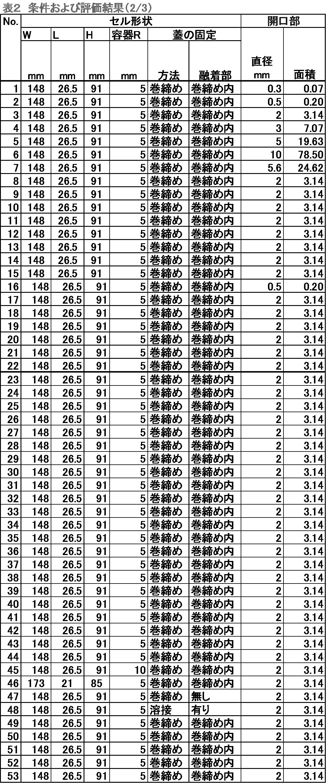

PE:ポリエチレン
PET:ポリエチレンテレフタレート
[参考符号の説明]
2 ・・・・・・容器蓋
3 ・・・・・・封止部
4 ・・・・・・接合部
5 ・・・・・・開口部シール
51・・・・・・金属箔
52、53・・・樹脂
6 ・・・・・・開口部(注液口)周辺
61・・・・・・鋼板
62、63・・・樹脂
7 ・・・・・・開口部(注液口)直径
8 ・・・・・・融着幅
9 ・・・・・・融着厚さ
容器蓋の開口部(注液口)を、抵抗溶接によって封止した。溶接によって封止できたものを「可」とし、封止できなかったものを「不可」とした。
No.4は、容器蓋の外面にポリプロピレンフィルムがラミネートされており、溶接熱でポリプロピレンが蒸発し、溶接不良が生じ、封止ができず、「不可」と評価した。
No.4以外では、いずれも溶接によって封止ができ、「可」と評価した。
(a)正極板
正極活物質としてコバルト酸リチウムを用いた。これにアセチレンブラックとポリフッ化ビニリデン(PVDF)を質量比で10:10:1となるよう混合したのち水性ディスパージョンとしてAl箔に塗布し、乾燥した。これを所定の厚みとなるよう圧延し、所定の大きさに切り出したものを正極板とした。
負極活物質には非晶質カーボンを用いた。これを導電材であるアセチレンブラックと乾式混合し、さらにポリフッ化ビニリデンを溶解させたN-メチルー2-ピロリドン(NMP)を混合物に均一に分散させて、質量比でカーボン:アセチレンブラック:PVDF=88:5:7となるペーストを作成した。これをCu箔に塗布し、乾燥したのち、所定厚みとなるよう圧延してから、所定の大きさに切り出したものを負極板とした。
セパレータにはポリエチレン微多孔膜を用いた。
電解液にはエチレンカーボネート:ジエチルカーボネートを体積比で1:1で混合したものに、6ふっ化りん酸リチウムを1mol/L添加した溶液(1M-LiPF6 EC/DEC(1/1))を用いた。
正極板と負極板の間にセパレータを挟んで捲回した電極群をセルケースに入る形状につぶし、正極板はAlリード、負極板はNiリードに溶接した。
図1のように、蓋に正極端子用および負極端子用の端子穴を備える電池セルケースでは、Alタブを正極端子に、Niリードを負極端子に溶接した。
図2のように、蓋に負極端子用の端子穴のみを有し、蓋が正極と同電位となるものは、Alタブを蓋に、Niタブを負極端子に溶接した。
図3のように、蓋に正極端子用の端子穴のみを有し、蓋が負極と同電位となるものは、Alタブを正極端子に、Niタブを蓋に溶接した。
露点-67℃の雰囲気で電池内を乾燥させ、水分を除去した。同雰囲気で上記の電解液を注入した。同雰囲気において電池を3.6Vで充電した。この処理により電池内に残った水分を電解除去した。その後、同雰囲気内で、開口部の蓋(封止材)として、容器蓋と同じ種類の金属を溶接した後、通常の大気雰囲気に取り出した。
(密閉性)
雰囲気温度85℃、相対湿度85%の環境で、封止した電池セルケースを蓋を下に向け保持した。保持開始から100日経過後に、電池セルケース内部の電解液を回収した。
回収した電解液を化学分析し、電解液中のふっ酸濃度を測定した。ふっ酸は、電池セルケース内に侵入した水分によって生成し、侵入した水分量が多いほどふっ酸濃度が高まると考えられ、以下の評点とした。
VG(Very Good):ふっ酸濃度が5ppm以下
G(Good):ふっ酸濃度が5ppm超、10ppm以下
P(Poor):ふっ酸濃度が10ppm超
溶接不可であったNo.4を除いて、全ての例で、良好な密閉性(GまたはVG)が確認された。特に、容器本体と容器蓋との組み付け(接合部)にヒートシールを施した例(No.12)、および組み付け(接合部)が溶接による例(No.18)では、さらに良好な密閉性(VG)が確認された。
密閉性の評価に続いて、回収した電解液を化学分析し、電解液中の金属イオン濃度を測定した。金属イオンは、容器本体を構成する鋼板および/または容器蓋を構成する金属板から電解液に溶出すると考えられ、以下の評点とした。
VG(Very Good):金属イオン濃度が10ppm以下
G(Good):金属イオン濃度が10ppm超、20ppm以下
P(Poor):金属イオン濃度が20ppm超
いずれの例でも、金属イオン濃度は低く(VGまたはG)であり、良好な耐食性が確認された。
別途、容器蓋の金属板をアルミ板として、容器蓋に正極端子用の端子穴を備え、容器蓋を負極と電気的に接続した電池セルケースについて、耐食性を評価したところ、電解液中の金属イオン濃度は20ppm超であることが確認された。
また、容器蓋の金属板をNiめっき鋼板として、容器蓋に負極端子用の端子穴を備え、容器蓋を正極と電気的に接続した電池セルケースについて、耐食性を評価したところ、電解液中の金属イオン濃度は20ppm超であることが確認された。

2 ・・・・・・蓋
3 ・・・・・・封止材
4 ・・・・・・注液口
5 ・・・・・・絶縁シール
61・・・・・・正極
62・・・・・・正極集電体
63・・・・・・正極タブ
64・・・・・・正極端子
71・・・・・・負極
72・・・・・・負極集電体
73・・・・・・負極タブ
74・・・・・・負極端子
Claims (9)
- 容器本体と容器蓋とを巻き締めまたは溶接により接合した電池セルケースであって、
前記容器本体は、その内面となる面に樹脂ラミネートされた鋼板からなり、
前記樹脂ラミネートがポリオレフィン系樹脂を主成分としたフィルムからなり、
前記容器蓋は金属板からなり、
前記容器蓋は、電解液の注液や予備充放電により発生したガス放出のための開口部を有し、
前記容器蓋の外面となる面において、前記開口部の周囲から少なくとも2mmの範囲は樹脂ラミネートがされていないことを特徴とする、電池セルケース。 - 前記容器本体の鋼板が、Al、Cr、Ni、Sn、Zn、Zr、Si、V、Ti、Pの少なくとも1つを含んだめっき処理および/またはSi、V、Ti、Zr、P、Crの少なくとも1つを含んだ化成処理を施された表面処理鋼板を基材とし、
前記容器蓋の金属板が、Niめっき鋼板、ステンレス鋼板、アルミ板のいずれかを基材とすることを特徴とする、請求項1に記載の電池セルケース。 - 前記開口部の直径が0.5mm以上、10mm以下であることを特徴とする、請求項1または請求項2に記載の電池セルケース。
- 前記容器蓋が、前記開口部のほかに、正極端子および負極端子用の端子穴を有することを特徴とする、請求項1~3のいずれか1項に記載の電池セルケース。
- 前記容器蓋の金属板がNiめっき鋼板またはステンレス鋼板のいずれかを基材とし、
前記容器蓋が、前記開口部のほかに、正極端子用の端子穴を有することを特徴とする、請求項1~3のいずれか1項に記載の電池セルケース。 - 前記容器蓋の金属板がステンレス鋼板またはアルミ板のいずれかを基材とし、
前記容器蓋が、前記開口部のほかに、負極端子用の端子穴を有することを特徴とする、請求項1~3のいずれか1項に記載の電池セルケース。 - 前記容器蓋の内面となる面にポリオレフィン系樹脂を主成分としたフィルムがラミネートされていることを特徴とする、請求項1~4のいずれか1項に記載の電池セルケース。
- 前記開口部が溶接により塞がれ密閉されていることを特徴とする、請求項1~7のいずれか1項に記載の電池セルケース。
- 請求項1~8のいずれか1項に記載の電池セルケースを用いた電池の製造方法であって、以下の工程:
前記容器本体に電池エレメントを挿入し;
前記容器本体と前記容器蓋を巻き締めまたは溶接により接合し;
前記開口部から電解液を注液し;
予備充放電により、前記電解液中の水分を分解しガス化して、前記電池セルケースから前記水分を放出し;そして、
前記開口部に金属の蓋を溶接することで、封止する;
を含んでなる、電池の製造方法。
Priority Applications (5)
| Application Number | Priority Date | Filing Date | Title |
|---|---|---|---|
| US17/765,800 US20220336935A1 (en) | 2019-10-03 | 2020-10-01 | Battery cell case and battery manufacturing method using same |
| CN202080061873.7A CN114365329B (zh) | 2019-10-03 | 2020-10-01 | 电池单元壳体和使用该壳体的电池的制造方法 |
| EP20871348.7A EP4040578A4 (en) | 2019-10-03 | 2020-10-01 | BATTERY CELL HOUSING AND METHOD OF MANUFACTURING BATTERY USING SUCH HOUSING |
| JP2021551464A JP7303458B2 (ja) | 2019-10-03 | 2020-10-01 | 電池セルケースおよびそれを用いた電池の製造方法 |
| KR1020227008126A KR20220047998A (ko) | 2019-10-03 | 2020-10-01 | 전지 셀 케이스 및 그것을 사용한 전지의 제조 방법 |
Applications Claiming Priority (2)
| Application Number | Priority Date | Filing Date | Title |
|---|---|---|---|
| JP2019182800 | 2019-10-03 | ||
| JP2019-182800 | 2019-10-03 |
Publications (1)
| Publication Number | Publication Date |
|---|---|
| WO2021066112A1 true WO2021066112A1 (ja) | 2021-04-08 |
Family
ID=75337061
Family Applications (1)
| Application Number | Title | Priority Date | Filing Date |
|---|---|---|---|
| PCT/JP2020/037469 WO2021066112A1 (ja) | 2019-10-03 | 2020-10-01 | 電池セルケースおよびそれを用いた電池の製造方法 |
Country Status (6)
| Country | Link |
|---|---|
| US (1) | US20220336935A1 (ja) |
| EP (1) | EP4040578A4 (ja) |
| JP (1) | JP7303458B2 (ja) |
| KR (1) | KR20220047998A (ja) |
| CN (1) | CN114365329B (ja) |
| WO (1) | WO2021066112A1 (ja) |
Cited By (1)
| Publication number | Priority date | Publication date | Assignee | Title |
|---|---|---|---|---|
| WO2023223791A1 (ja) * | 2022-05-17 | 2023-11-23 | パナソニックエナジー株式会社 | 円筒形電池 |
Citations (11)
| Publication number | Priority date | Publication date | Assignee | Title |
|---|---|---|---|---|
| JP2001243953A (ja) * | 2000-02-29 | 2001-09-07 | Osaka Gas Co Ltd | 非水系二次電池 |
| JP2001243980A (ja) * | 2000-02-29 | 2001-09-07 | Osaka Gas Co Ltd | 非水系二次電池 |
| JP2002246068A (ja) * | 2001-02-15 | 2002-08-30 | Osaka Gas Co Ltd | 非水系二次電池 |
| JP2008251381A (ja) * | 2007-03-30 | 2008-10-16 | Kri Inc | 非水系二次電池 |
| JP2009245709A (ja) * | 2008-03-31 | 2009-10-22 | Kri Inc | 蓄電デバイスモジュール |
| JP2010087170A (ja) * | 2008-09-30 | 2010-04-15 | Fdk Corp | 蓄電デバイス |
| JP2011258501A (ja) | 2010-06-11 | 2011-12-22 | Nisshin Steel Co Ltd | 電池用ケースの製造方法 |
| JP2012018866A (ja) | 2010-07-09 | 2012-01-26 | Nisshin Steel Co Ltd | 電池用ケースの製造方法及び電池用ケース |
| JP2012064337A (ja) | 2010-09-14 | 2012-03-29 | Denso Corp | 密閉型蓄電池 |
| JP2012094374A (ja) | 2010-10-27 | 2012-05-17 | Enax Inc | ラミネート式電池の外装材、ラミネート式電池の外装材製造方法、ラミネート式電池の製造方法、及びラミネート式電池 |
| JP2019107770A (ja) | 2017-08-30 | 2019-07-04 | 三菱日立ツール株式会社 | 切削インサート、刃先交換式ボールエンドミル、および刃先交換式ボールエンドミルのエンドミル本体 |
Family Cites Families (8)
| Publication number | Priority date | Publication date | Assignee | Title |
|---|---|---|---|---|
| JP2004330533A (ja) * | 2003-05-02 | 2004-11-25 | Toyo Kohan Co Ltd | 安全装置、および安全装置を備えた部品、および安全装置を備えた容器 |
| JP5080738B2 (ja) * | 2005-12-20 | 2012-11-21 | 新日鉄マテリアルズ株式会社 | 樹脂被覆ステンレス鋼箔,容器及び2次電池 |
| WO2013132673A1 (ja) * | 2012-03-05 | 2013-09-12 | 新日鉄住金マテリアルズ株式会社 | 樹脂金属複合シール容器及びその製造方法 |
| JP6017873B2 (ja) * | 2012-07-27 | 2016-11-02 | トヨタ自動車株式会社 | 密閉型電池 |
| CN203165991U (zh) * | 2013-03-08 | 2013-08-28 | 宁德新能源科技有限公司 | 锂离子电池注液孔封口装置 |
| JP6374969B2 (ja) * | 2014-08-05 | 2018-08-15 | 昭和電工株式会社 | 金属箔と樹脂フィルムのラミネート用接着剤、該組成物を用いた積層体、電池外装用包装材および電池ケース |
| JP6583837B2 (ja) * | 2016-02-03 | 2019-10-02 | 昭和電工株式会社 | 金属箔と樹脂フィルムのラミネート用接着剤、積層体、電池外装用包装材並びに電池ケース及びその製造方法 |
| JP6752628B2 (ja) * | 2016-06-03 | 2020-09-09 | 太陽誘電株式会社 | 蓄電セル及び蓄電モジュール |
-
2020
- 2020-10-01 JP JP2021551464A patent/JP7303458B2/ja active Active
- 2020-10-01 US US17/765,800 patent/US20220336935A1/en active Pending
- 2020-10-01 CN CN202080061873.7A patent/CN114365329B/zh active Active
- 2020-10-01 EP EP20871348.7A patent/EP4040578A4/en active Pending
- 2020-10-01 KR KR1020227008126A patent/KR20220047998A/ko unknown
- 2020-10-01 WO PCT/JP2020/037469 patent/WO2021066112A1/ja active Application Filing
Patent Citations (11)
| Publication number | Priority date | Publication date | Assignee | Title |
|---|---|---|---|---|
| JP2001243953A (ja) * | 2000-02-29 | 2001-09-07 | Osaka Gas Co Ltd | 非水系二次電池 |
| JP2001243980A (ja) * | 2000-02-29 | 2001-09-07 | Osaka Gas Co Ltd | 非水系二次電池 |
| JP2002246068A (ja) * | 2001-02-15 | 2002-08-30 | Osaka Gas Co Ltd | 非水系二次電池 |
| JP2008251381A (ja) * | 2007-03-30 | 2008-10-16 | Kri Inc | 非水系二次電池 |
| JP2009245709A (ja) * | 2008-03-31 | 2009-10-22 | Kri Inc | 蓄電デバイスモジュール |
| JP2010087170A (ja) * | 2008-09-30 | 2010-04-15 | Fdk Corp | 蓄電デバイス |
| JP2011258501A (ja) | 2010-06-11 | 2011-12-22 | Nisshin Steel Co Ltd | 電池用ケースの製造方法 |
| JP2012018866A (ja) | 2010-07-09 | 2012-01-26 | Nisshin Steel Co Ltd | 電池用ケースの製造方法及び電池用ケース |
| JP2012064337A (ja) | 2010-09-14 | 2012-03-29 | Denso Corp | 密閉型蓄電池 |
| JP2012094374A (ja) | 2010-10-27 | 2012-05-17 | Enax Inc | ラミネート式電池の外装材、ラミネート式電池の外装材製造方法、ラミネート式電池の製造方法、及びラミネート式電池 |
| JP2019107770A (ja) | 2017-08-30 | 2019-07-04 | 三菱日立ツール株式会社 | 切削インサート、刃先交換式ボールエンドミル、および刃先交換式ボールエンドミルのエンドミル本体 |
Non-Patent Citations (1)
| Title |
|---|
| See also references of EP4040578A4 |
Cited By (1)
| Publication number | Priority date | Publication date | Assignee | Title |
|---|---|---|---|---|
| WO2023223791A1 (ja) * | 2022-05-17 | 2023-11-23 | パナソニックエナジー株式会社 | 円筒形電池 |
Also Published As
| Publication number | Publication date |
|---|---|
| JPWO2021066112A1 (ja) | 2021-04-08 |
| KR20220047998A (ko) | 2022-04-19 |
| EP4040578A4 (en) | 2023-03-15 |
| CN114365329A (zh) | 2022-04-15 |
| EP4040578A1 (en) | 2022-08-10 |
| US20220336935A1 (en) | 2022-10-20 |
| CN114365329B (zh) | 2024-03-22 |
| JP7303458B2 (ja) | 2023-07-05 |
Similar Documents
| Publication | Publication Date | Title |
|---|---|---|
| US7749652B2 (en) | Lead and nonaqueous electrolyte battery including same | |
| US20030031926A1 (en) | Tab surface treatments for polymer-metal laminate electrochemical cell packages | |
| KR100449213B1 (ko) | 개선된 표면처리 리드 단자를 가진 막 밀봉형 비수성전해질 전지 | |
| WO2013132673A1 (ja) | 樹脂金属複合シール容器及びその製造方法 | |
| US20130108915A1 (en) | Electrical part, nonaqueous electrolyte cell, and lead wire and sealable container which are used therein | |
| JP5959878B2 (ja) | 電極リード線部材を備えた非水系電池用収納容器 | |
| JP7045545B2 (ja) | 絶縁コーティング層が備えられた電極タブを含む二次電池 | |
| KR102100628B1 (ko) | 비수계 전지용 전극 리드선 부재 | |
| JP2012048852A (ja) | 非水系電池用の電極リード線部材 | |
| JP5939436B2 (ja) | 非水電解質二次電池およびその製造方法 | |
| JP6816937B2 (ja) | 蓄電デバイス | |
| WO2021066112A1 (ja) | 電池セルケースおよびそれを用いた電池の製造方法 | |
| JP7364881B2 (ja) | 電池セルケース | |
| JP5856693B2 (ja) | 非水系電池用の電極リード線部材 | |
| KR20050100448A (ko) | 리튬 2차 전지 및 휴대용 축전지 셀 포장용 봉지재 | |
| JP3237526U (ja) | 電池用ケース | |
| JP2004031161A (ja) | 組電池 | |
| JP2001155713A (ja) | 電極リード部材及び電池 | |
| WO2020250950A1 (ja) | 電池用ケースおよびその製造方法 | |
| JP2017212216A (ja) | 電極リード線部材を備えた非水系電池用収納容器の製造方法 | |
| JP7193239B2 (ja) | 非水電解質二次電池の製造方法及び非水電解質二次電池 | |
| JP6180054B2 (ja) | 電極リード線部材を備えた非水系電池用収納容器の製造方法 | |
| JP2018163896A (ja) | 非水系電池用の電極リード線部材の製造方法 | |
| JP5825389B2 (ja) | 電気化学セル用包装材料 | |
| JP2014195910A (ja) | 樹脂被覆アルミニウム合金箔及びその製造方法 |
Legal Events
| Date | Code | Title | Description |
|---|---|---|---|
| 121 | Ep: the epo has been informed by wipo that ep was designated in this application |
Ref document number: 20871348 Country of ref document: EP Kind code of ref document: A1 |
|
| WWE | Wipo information: entry into national phase |
Ref document number: 2021551464 Country of ref document: JP |
|
| ENP | Entry into the national phase |
Ref document number: 20227008126 Country of ref document: KR Kind code of ref document: A |
|
| NENP | Non-entry into the national phase |
Ref country code: DE |
|
| ENP | Entry into the national phase |
Ref document number: 2020871348 Country of ref document: EP Effective date: 20220503 |