WO2021049603A1 - 窒素回収方法、窒素回収装置、およびこれにより得られる製品 - Google Patents
窒素回収方法、窒素回収装置、およびこれにより得られる製品 Download PDFInfo
- Publication number
- WO2021049603A1 WO2021049603A1 PCT/JP2020/034429 JP2020034429W WO2021049603A1 WO 2021049603 A1 WO2021049603 A1 WO 2021049603A1 JP 2020034429 W JP2020034429 W JP 2020034429W WO 2021049603 A1 WO2021049603 A1 WO 2021049603A1
- Authority
- WO
- WIPO (PCT)
- Prior art keywords
- ammonia
- circulating water
- water
- nitrifying
- nitrogen
- Prior art date
Links
Images

Classifications
-
- B—PERFORMING OPERATIONS; TRANSPORTING
- B01—PHYSICAL OR CHEMICAL PROCESSES OR APPARATUS IN GENERAL
- B01D—SEPARATION
- B01D53/00—Separation of gases or vapours; Recovering vapours of volatile solvents from gases; Chemical or biological purification of waste gases, e.g. engine exhaust gases, smoke, fumes, flue gases, aerosols
- B01D53/34—Chemical or biological purification of waste gases
- B01D53/46—Removing components of defined structure
- B01D53/54—Nitrogen compounds
- B01D53/58—Ammonia
-
- B—PERFORMING OPERATIONS; TRANSPORTING
- B01—PHYSICAL OR CHEMICAL PROCESSES OR APPARATUS IN GENERAL
- B01D—SEPARATION
- B01D53/00—Separation of gases or vapours; Recovering vapours of volatile solvents from gases; Chemical or biological purification of waste gases, e.g. engine exhaust gases, smoke, fumes, flue gases, aerosols
- B01D53/34—Chemical or biological purification of waste gases
- B01D53/74—General processes for purification of waste gases; Apparatus or devices specially adapted therefor
- B01D53/84—Biological processes
-
- C—CHEMISTRY; METALLURGY
- C01—INORGANIC CHEMISTRY
- C01B—NON-METALLIC ELEMENTS; COMPOUNDS THEREOF; METALLOIDS OR COMPOUNDS THEREOF NOT COVERED BY SUBCLASS C01C
- C01B21/00—Nitrogen; Compounds thereof
- C01B21/20—Nitrogen oxides; Oxyacids of nitrogen; Salts thereof
- C01B21/24—Nitric oxide (NO)
- C01B21/26—Preparation by catalytic or non-catalytic oxidation of ammonia
-
- C—CHEMISTRY; METALLURGY
- C01—INORGANIC CHEMISTRY
- C01B—NON-METALLIC ELEMENTS; COMPOUNDS THEREOF; METALLOIDS OR COMPOUNDS THEREOF NOT COVERED BY SUBCLASS C01C
- C01B21/00—Nitrogen; Compounds thereof
- C01B21/20—Nitrogen oxides; Oxyacids of nitrogen; Salts thereof
- C01B21/38—Nitric acid
- C01B21/40—Preparation by absorption of oxides of nitrogen
-
- C—CHEMISTRY; METALLURGY
- C05—FERTILISERS; MANUFACTURE THEREOF
- C05C—NITROGENOUS FERTILISERS
- C05C5/00—Fertilisers containing other nitrates
-
- C—CHEMISTRY; METALLURGY
- C05—FERTILISERS; MANUFACTURE THEREOF
- C05G—MIXTURES OF FERTILISERS COVERED INDIVIDUALLY BY DIFFERENT SUBCLASSES OF CLASS C05; MIXTURES OF ONE OR MORE FERTILISERS WITH MATERIALS NOT HAVING A SPECIFIC FERTILISING ACTIVITY, e.g. PESTICIDES, SOIL-CONDITIONERS, WETTING AGENTS; FERTILISERS CHARACTERISED BY THEIR FORM
- C05G5/00—Fertilisers characterised by their form
- C05G5/20—Liquid fertilisers
-
- C—CHEMISTRY; METALLURGY
- C12—BIOCHEMISTRY; BEER; SPIRITS; WINE; VINEGAR; MICROBIOLOGY; ENZYMOLOGY; MUTATION OR GENETIC ENGINEERING
- C12M—APPARATUS FOR ENZYMOLOGY OR MICROBIOLOGY; APPARATUS FOR CULTURING MICROORGANISMS FOR PRODUCING BIOMASS, FOR GROWING CELLS OR FOR OBTAINING FERMENTATION OR METABOLIC PRODUCTS, i.e. BIOREACTORS OR FERMENTERS
- C12M25/00—Means for supporting, enclosing or fixing the microorganisms, e.g. immunocoatings
- C12M25/16—Particles; Beads; Granular material; Encapsulation
- C12M25/18—Fixed or packed bed
-
- C—CHEMISTRY; METALLURGY
- C12—BIOCHEMISTRY; BEER; SPIRITS; WINE; VINEGAR; MICROBIOLOGY; ENZYMOLOGY; MUTATION OR GENETIC ENGINEERING
- C12M—APPARATUS FOR ENZYMOLOGY OR MICROBIOLOGY; APPARATUS FOR CULTURING MICROORGANISMS FOR PRODUCING BIOMASS, FOR GROWING CELLS OR FOR OBTAINING FERMENTATION OR METABOLIC PRODUCTS, i.e. BIOREACTORS OR FERMENTERS
- C12M29/00—Means for introduction, extraction or recirculation of materials, e.g. pumps
- C12M29/06—Nozzles; Sprayers; Spargers; Diffusers
-
- C—CHEMISTRY; METALLURGY
- C12—BIOCHEMISTRY; BEER; SPIRITS; WINE; VINEGAR; MICROBIOLOGY; ENZYMOLOGY; MUTATION OR GENETIC ENGINEERING
- C12M—APPARATUS FOR ENZYMOLOGY OR MICROBIOLOGY; APPARATUS FOR CULTURING MICROORGANISMS FOR PRODUCING BIOMASS, FOR GROWING CELLS OR FOR OBTAINING FERMENTATION OR METABOLIC PRODUCTS, i.e. BIOREACTORS OR FERMENTERS
- C12M29/00—Means for introduction, extraction or recirculation of materials, e.g. pumps
- C12M29/26—Conditioning fluids entering or exiting the reaction vessel
-
- C—CHEMISTRY; METALLURGY
- C12—BIOCHEMISTRY; BEER; SPIRITS; WINE; VINEGAR; MICROBIOLOGY; ENZYMOLOGY; MUTATION OR GENETIC ENGINEERING
- C12M—APPARATUS FOR ENZYMOLOGY OR MICROBIOLOGY; APPARATUS FOR CULTURING MICROORGANISMS FOR PRODUCING BIOMASS, FOR GROWING CELLS OR FOR OBTAINING FERMENTATION OR METABOLIC PRODUCTS, i.e. BIOREACTORS OR FERMENTERS
- C12M41/00—Means for regulation, monitoring, measurement or control, e.g. flow regulation
- C12M41/26—Means for regulation, monitoring, measurement or control, e.g. flow regulation of pH
-
- C—CHEMISTRY; METALLURGY
- C12—BIOCHEMISTRY; BEER; SPIRITS; WINE; VINEGAR; MICROBIOLOGY; ENZYMOLOGY; MUTATION OR GENETIC ENGINEERING
- C12M—APPARATUS FOR ENZYMOLOGY OR MICROBIOLOGY; APPARATUS FOR CULTURING MICROORGANISMS FOR PRODUCING BIOMASS, FOR GROWING CELLS OR FOR OBTAINING FERMENTATION OR METABOLIC PRODUCTS, i.e. BIOREACTORS OR FERMENTERS
- C12M47/00—Means for after-treatment of the produced biomass or of the fermentation or metabolic products, e.g. storage of biomass
- C12M47/10—Separation or concentration of fermentation products
-
- C—CHEMISTRY; METALLURGY
- C12—BIOCHEMISTRY; BEER; SPIRITS; WINE; VINEGAR; MICROBIOLOGY; ENZYMOLOGY; MUTATION OR GENETIC ENGINEERING
- C12N—MICROORGANISMS OR ENZYMES; COMPOSITIONS THEREOF; PROPAGATING, PRESERVING, OR MAINTAINING MICROORGANISMS; MUTATION OR GENETIC ENGINEERING; CULTURE MEDIA
- C12N1/00—Microorganisms, e.g. protozoa; Compositions thereof; Processes of propagating, maintaining or preserving microorganisms or compositions thereof; Processes of preparing or isolating a composition containing a microorganism; Culture media therefor
- C12N1/20—Bacteria; Culture media therefor
-
- C—CHEMISTRY; METALLURGY
- C12—BIOCHEMISTRY; BEER; SPIRITS; WINE; VINEGAR; MICROBIOLOGY; ENZYMOLOGY; MUTATION OR GENETIC ENGINEERING
- C12N—MICROORGANISMS OR ENZYMES; COMPOSITIONS THEREOF; PROPAGATING, PRESERVING, OR MAINTAINING MICROORGANISMS; MUTATION OR GENETIC ENGINEERING; CULTURE MEDIA
- C12N11/00—Carrier-bound or immobilised enzymes; Carrier-bound or immobilised microbial cells; Preparation thereof
- C12N11/14—Enzymes or microbial cells immobilised on or in an inorganic carrier
-
- C—CHEMISTRY; METALLURGY
- C12—BIOCHEMISTRY; BEER; SPIRITS; WINE; VINEGAR; MICROBIOLOGY; ENZYMOLOGY; MUTATION OR GENETIC ENGINEERING
- C12P—FERMENTATION OR ENZYME-USING PROCESSES TO SYNTHESISE A DESIRED CHEMICAL COMPOUND OR COMPOSITION OR TO SEPARATE OPTICAL ISOMERS FROM A RACEMIC MIXTURE
- C12P3/00—Preparation of elements or inorganic compounds except carbon dioxide
-
- B—PERFORMING OPERATIONS; TRANSPORTING
- B01—PHYSICAL OR CHEMICAL PROCESSES OR APPARATUS IN GENERAL
- B01D—SEPARATION
- B01D2251/00—Reactants
- B01D2251/95—Specific microorganisms
-
- B—PERFORMING OPERATIONS; TRANSPORTING
- B01—PHYSICAL OR CHEMICAL PROCESSES OR APPARATUS IN GENERAL
- B01D—SEPARATION
- B01D2258/00—Sources of waste gases
- B01D2258/02—Other waste gases
- B01D2258/0266—Other waste gases from animal farms
-
- C—CHEMISTRY; METALLURGY
- C12—BIOCHEMISTRY; BEER; SPIRITS; WINE; VINEGAR; MICROBIOLOGY; ENZYMOLOGY; MUTATION OR GENETIC ENGINEERING
- C12M—APPARATUS FOR ENZYMOLOGY OR MICROBIOLOGY; APPARATUS FOR CULTURING MICROORGANISMS FOR PRODUCING BIOMASS, FOR GROWING CELLS OR FOR OBTAINING FERMENTATION OR METABOLIC PRODUCTS, i.e. BIOREACTORS OR FERMENTERS
- C12M21/00—Bioreactors or fermenters specially adapted for specific uses
-
- C—CHEMISTRY; METALLURGY
- C12—BIOCHEMISTRY; BEER; SPIRITS; WINE; VINEGAR; MICROBIOLOGY; ENZYMOLOGY; MUTATION OR GENETIC ENGINEERING
- C12M—APPARATUS FOR ENZYMOLOGY OR MICROBIOLOGY; APPARATUS FOR CULTURING MICROORGANISMS FOR PRODUCING BIOMASS, FOR GROWING CELLS OR FOR OBTAINING FERMENTATION OR METABOLIC PRODUCTS, i.e. BIOREACTORS OR FERMENTERS
- C12M47/00—Means for after-treatment of the produced biomass or of the fermentation or metabolic products, e.g. storage of biomass
- C12M47/18—Gas cleaning, e.g. scrubbers; Separation of different gases
-
- Y—GENERAL TAGGING OF NEW TECHNOLOGICAL DEVELOPMENTS; GENERAL TAGGING OF CROSS-SECTIONAL TECHNOLOGIES SPANNING OVER SEVERAL SECTIONS OF THE IPC; TECHNICAL SUBJECTS COVERED BY FORMER USPC CROSS-REFERENCE ART COLLECTIONS [XRACs] AND DIGESTS
- Y02—TECHNOLOGIES OR APPLICATIONS FOR MITIGATION OR ADAPTATION AGAINST CLIMATE CHANGE
- Y02A—TECHNOLOGIES FOR ADAPTATION TO CLIMATE CHANGE
- Y02A50/00—TECHNOLOGIES FOR ADAPTATION TO CLIMATE CHANGE in human health protection, e.g. against extreme weather
- Y02A50/20—Air quality improvement or preservation, e.g. vehicle emission control or emission reduction by using catalytic converters
Definitions
- the present invention relates to a nitrogen recovery method, a nitrogen recovery device, and a product obtained by the method. More specifically, the present invention relates to a nitrogen recovery method for recovering nitrogen with high efficiency from ammonia gas generated in a livestock facility, a compost house, a sewage treatment plant, etc., a nitrogen recovery device, and a product obtained by the method.
- the following techniques have been conventionally known as a technique for decomposing a large amount of malodorous ammonia gas generated from livestock facilities, compost houses, sewage treatment plants, etc. into nitric acid using nitrifying bacteria.
- Patent Document 1 a deodorizing tank filled with a deodorizing material inoculated with activated sludge, which is subjected to an ammonia gas for a nitrification reaction and a sulfur denitrification reaction, and a supply of water containing sodium thiosulfate to the deodorizing tank.
- a deodorizing and denitrifying treatment device including a water tank has been proposed.
- the accumulation of inorganic nitrogen in circulating water can be suppressed by combining the sulfur denitrification reaction and the nitrification reaction, and the deodorization treatment of ammonia gas can be performed for a long period of time. Is shown.
- Patent Document 1 thiosulfuric acid reacts with nitrite and nitric acid produced in the deodorizing tank, and thiosulfuric acid is oxidized to produce sulfuric acid, which removes the inorganic nitrogen of nitrite and nitric acid as nitrogen gas. Yes, the recovery or effective utilization of ammoniacal nitrogen has not been attempted.
- Patent Document 2 circulating water is intermittently sprinkled on a packed bed filled with a carrier of microorganisms, and nitric acid groups and nitrite groups generated by the nitric acid reaction of ammonia in gas by microorganisms and ammonia groups in gas are used.
- a refillable biological deodorizing tower that cleans ammonium nitrate and ammonium nitrite generated by the chemical reaction of the above and accumulated in the carrier, acid is added to the circulating water to suppress the pH value of the circulating water to 7.5 or less and to circulate.
- a refillable biological deodorizing tower has been proposed, which comprises controlling the concentration of ammoniacal nitrogen in water to 1000 mg-N / L or less.
- Patent Document 2 sulfuric acid is added to the circulating water to suppress the ammonia nitrogen concentration in the circulating water in order to prevent the nitrification rate of ammonia by microorganisms from decreasing as the ammonia nitrogen concentration in the circulating water increases.
- ammoniacal nitrogen has not been recovered or effectively utilized.
- ammonia gas is introduced into a microbial carrier storage tank containing a microbial carrier carrying ammonia-oxidizing bacteria for nitriding ammonia, and water is sprinkled into the microbial carrier storage tank.
- Ammonia gas is dissolved in sprinkled water, ammonia dissolved in water by the ammonia-oxidizing bacteria is oxidized to nitrite nitrogen, the sprinkled water is recovered as circulating water, and the ammonium ion concentration in the circulating water is 500 mg /
- a method for treating an ammonia-containing gas has been proposed, which comprises adjusting the concentration of L or more and / and the nitrite nitrogen concentration to 650 mg / L or more and subjecting the mixture to the watering.
- Patent Document 4 an absorption tank that absorbs ammonia generated by anaerobic decomposition of food waste into a cultivation nutrient solution, and a circulation device that circulates the cultivation nutrient solution that has absorbed ammonia to a cultivation nutrient solution tank for hydroponics.
- a hydroponic cultivation device characterized by arranging a hydroponic cultivation facility having a cultivation nutrient solution tank has been proposed, and ammonia accumulated in the cultivation nutrient solution is generated by nitrifying bacteria attached to a porous carrier. It has also been shown to convert to nitric acid.
- Patent Document 5 proposes that ammonia gas is introduced into soil containing nitrifying bacteria corresponding to a nitrifying bacterium carrier, and the decomposition products (nitrate, etc.) of ammonia gas by nitrifying bacteria are fixed in the soil. ing.
- nitrifying bacteria are present in the soil, whereby ammonia is oxidatively decomposed into nitrite or nitric acid, which is adsorbed in the soil.
- the soil for ammonia treatment in which the nitrogen thus obtained is fixed as an inorganic state is used as the soil for plant cultivation, but as described above, nitrifying bacteria that decompose ammonia are present in the soil. ing. Therefore, when it is used as soil for cultivation, nitrifying bacteria are also removed from the production system and consumed each time, which is not efficient.
- a partial nitrification treatment tank and the partial nitrification treatment tank which are provided with an aeration means and in which a liquid to be treated containing at least ammonia nitrogen is aerated in the presence of ammonia-oxidizing bacteria, and the partial nitrification treatment tank.
- a denitrification treatment tank that treats the liquid to be treated in the above manner in the presence of anaerobic ammonia-oxidizing bacteria and reacts the ammoniacal nitrogen with the nitrite nitrogen to convert it into nitrogen gas, and the denitrification treatment tank.
- An inorganic carbon component adjusting tank that injects an inorganic carbon component into the liquid to be treated according to the nitrite nitrogen concentration of the liquid to be treated, and a liquid to be treated that is introduced into the denitrification tank.
- a method for treating an ammoniacal nitrogen-containing liquid which comprises a pH adjusting tank for injecting a pH adjusting agent containing phosphorus, the above, depending on the nitrite nitrogen concentration of the liquid to be treated, which is subjected to the denitrification step.
- Patent Document 6 A method for treating an ammoniacal nitrogen-containing liquid in which an inorganic carbon component is injected into the liquid to be treated and the pH of the liquid to be treated to be subjected to the denitrification step is adjusted with a pH adjusting agent containing phosphorus has been proposed.
- the technique shown in Patent Document 6 is a technique obtained by biodegrading a liquid to be treated containing ammoniacal nitrogen and efficiently reacting ammoniacal nitrogen with nitrite nitrogen to obtain nitrogen gas. Therefore, it has not been collected or effectively used.
- the present invention also provides a nitrogen recovery method for recovering nitrogen components from ammonia gas generated in livestock facilities, compost houses, sewage treatment plants, etc. with high efficiency, a nitrogen recovery device, and products such as liquid fertilizer obtained thereby. Is the subject.
- the present invention that solves the above-mentioned problems is a nitrogen recovery method in which an ammonia component in an ammonia-containing gas is decomposed by a nitrifying bacterium and the ammonia-containing nitrogen component is recovered as an ammonia gas decomposition product, and the nitrifying bacterium is supported. Circulating water is supplied to the microbial decomposition tank that holds the nitrified bacterium carrier to keep the nitrified bacterium carrier in a wet state, and the moistened nitrified bacterium carrier is subjected to an oxygen presence atmosphere.
- Ammonia-containing gas is aerated, the ammonia component in the ammonia-containing gas and the ammonia gas decomposition product decomposed by nitrifying bacteria are dissolved in the circulating water, and the ammonia gas decomposition product is accumulated in the circulating water.
- the decomposition treatment of the ammonia-containing gas is continued and the nitrate ion concentration as an ammonia decomposition product in the circulating water is increased to 5000 mg / L or more and reaches a predetermined concentration, a part or all of the circulating water is ammonia. It is a nitrogen recovery method characterized by recovering as a gas decomposition product.
- the nitrifying bacterium carrier is an inorganic porous body and / or an inorganic fibrous body, for example, foamed glass.
- the nitrifying bacterium carrier is an inorganic porous body and / or an inorganic fibrous body, for example, foamed glass.
- it can be used as long as it is a porous body or a fibrous body of an organic substance such as plastic, rubber, or resin that does not generate an odor due to putrefaction.
- the water content of the nitrifying bacterium carrier in the microbial decomposition tank is 5 to 90%.
- the circulating water supplied to the microbial decomposition tank has a water amount of 50 to 50,000 mL / hour per 1 L of the filling volume of the nitrifying bacterium carrier.
- the "filling volume of the nitrifying bacterium carrier 1L" is expressed as a volume of the amount of the nitrifying bacterium carrier when the container having a volume of 1L is filled with the nitrifying bacterium carrier until it is cut into pieces.
- the circulating water is aerated so that the amount of aeration per 1 L of the circulating water is 0.5 to 10 L / min.
- circulating water maintains a pH in the range of 5.0 to 9.0 and a temperature in the range of 10 to 60 ° C.
- the nitrifying bacteria carried on the nitrifying bacteria carrier include an ammonia-oxidizing bacterium group (AOB) and a nitrite-oxidizing bacterium group (NOB). Is done.
- AOB ammonia-oxidizing bacterium group
- NOB nitrite-oxidizing bacterium group
- the nitrogen recovery method of the present invention when the nitrate ion concentration in the circulating water increases by 5000 mg / L or more from the concentration at the time when the aeration of the ammonia-containing gas is started in the above nitrogen recovery method.
- a nitrogen recovery method for recovering a part or all of the circulating water as an ammonia gas decomposition product is shown.
- the ammonia-containing gas is derived from a manure treatment or sewage treatment facility.
- the present invention that solves the above problems is also a nitrogen recovery device that decomposes an ammonia component in an ammonia-containing gas with a nitrifying bacterium and recovers the ammonia-containing nitrogen component as an ammonia gas decomposition product.
- a microbial decomposition tank having a nitrifying bacterium carrier carrying a nitrifying bacterium and decomposing the ammonia-containing gas in an oxygen-presence atmosphere.
- (G) A circulating means for circulating the water containing the ammonia gas decomposition product between the microbial decomposition tank, the drainage line, the storage tank, and the reprocessing line.
- (H) Achieved by a nitrogen recovery device including a recovery means for recovering a part or all of water (circulating water) containing the ammonia gas decomposition product having a predetermined nitrate ion concentration from the storage tank. ..
- the nitrifying bacterium carrier is an inorganic porous body and / or an inorganic fibrous body, for example, foamed glass.
- the nitrifying bacterium carrier is an inorganic porous body and / or an inorganic fibrous body, for example, foamed glass.
- it can be used as long as it is a porous body or a fibrous body of an organic substance such as plastic, rubber, or resin that does not generate an odor due to putrefaction.
- the microbial decomposition tank has a vertically long shape, and shows a countercurrent contact type in which ammonia-containing gas is supplied from the lower side and water is supplied from the upper side. Is done.
- a nitrifying bacterium including an ammonia-oxidizing bacterium group (AOB) and a nitrite-oxidizing bacterium group (NOB) is shown.
- AOB ammonia-oxidizing bacterium group
- NOB nitrite-oxidizing bacterium group
- the present invention that solves the above problems also includes products such as liquid fertilizer made of water containing an ammonia gas decomposition product recovered by the nitrogen recovery method, and solid fertilizer produced by extracting a nitrogen component from the liquid fertilizer. It is also achieved by (for example, crystallizing and recovering nitric acid in circulating water).
- nitrogen components can be recovered with high efficiency from ammonia gas generated in livestock facilities, compost houses, sewage treatment plants, etc., and the recovered nitrogen is retained in water at a high concentration as nitrate ions. Therefore, it can be effectively used as fertilizer as it is.
- FIG. 1 is a diagram schematically showing a configuration of an embodiment of the nitrogen recovery device of the present invention.
- the ammonia gas source tank 10 and the microbial decomposition tank 20 which is a reaction field for decomposing the ammonia-containing gas generated in the ammonia gas source tank 10 are provided. I have. Further, a water supply line 30 that supplies water from the upper side of the microbial decomposition tank 20, a drainage line 40 that draws water that has passed through the inside of the microbial decomposition tank 20 from the bottom side of the microbial decomposition tank 20, and a drainage line 40 that discharges the water.
- the storage tank 50 that temporarily stores the water is connected to the storage tank 50 and the upper side of the microbial decomposition tank 20, and the water stored in the storage tank 50 is sent to the microbial decomposition tank again. It has a processing line 70. Then, a circulation pump (for example, a pump) 60 is installed in the storage tank 50 as a circulation means for circulating the water between the microbial decomposition tank 20, the drainage line 40, the storage tank 50, and the reprocessing line 70. It is arranged inside.
- a circulation pump for example, a pump
- a nitrate aqueous solution recovery line 80 having a valve that can be opened and closed is provided as a recovery means for recovering water from the storage tank 50 when the water in the storage tank 50 reaches a predetermined nitrate ion concentration. It is provided. Further, a pH sensor 91 for measuring the pH of water in the storage tank is arranged in the storage tank 50, and is electrically connected to a pH controller 90 outside the storage tank. The pH controller 90 can control the operation of either the discharge pump (not shown) of the alkaline liquid tank 101 or the acid liquid tank 102 by a changeover switch (not shown), and the pH value measured by the pH sensor 91.
- the alkaline solution or acid solution is sent from the alkaline solution tank 101 or the acid solution tank 102 to the storage tank 50 through the pH adjuster supply line 100, and the pH of the water is adjusted to the predetermined pH value. It is configured to automatically adjust to the pH value.
- each component will be described in more detail.
- ammonia-containing gas supply means The ammonia gas source tank 10 is not an essential configuration in the nitrogen recovery device according to the present invention, and generates an ammonia-containing gas as a part of the ammonia-containing gas supply means for supplying the ammonia-containing gas to the microbial decomposition tank 20. If it is a thing, it is not particularly limited.
- the ammonia gas source tank 10 is used for solid-liquid separated sewage in a livestock excrement treatment process such as a composting process for livestock manure and wastewater having a high ammonia nitrogen concentration obtained by organically decomposing the sewage. Therefore, it can be configured to generate an ammonia-containing gas by an ammonia stripping method.
- the type of waste liquid does not have to be limited to livestock waste liquid.
- the type of waste liquid is such that ammonium ions contained in the waste liquid discharged from a food factory or generated in the treatment process are generated by the ammonia stripping method. can do.
- the ammonia-containing gas supply means is not limited to the embodiment having the ammonia gas source tank 10 as described above.
- various facilities generally have an odor, for example, an odor gas in the composting treatment of livestock manure as described above, an odor gas in the livestock industry, composting, and an odor gas in waste water treatment. Odor gas in the industrial waste treatment process or exhaust gas in various production processes may be included, and the ammonia-containing gas supply means is the one that captures and recovers these ammonia-containing gases directly from the source or once. It may be supplied indirectly from.
- these ammonia-containing gases may contain hydrogen sulfide, mercaptans, amines, aldehydes, fatty acids, aromatics, and the like.
- the upper limit of the total amount of ammonia in the ammonia-containing gas supplied from the ammonia-containing gas supply means is, for example, 2000 mg or less per day for 1 L of the nitrifying bacterium carrier-filled volume. 1800 mg or less, 1600 mg or less, 1400 mg or less, 1200 mg or less, 1000 mg or less, 800 mg or less, 700 mg or less, 600 mg or less, 500 mg or less.
- the lower limit is not particularly limited, but if the supply of ammonia gas is completely stopped for a long period of time, the activity of nitrifying bacteria may decrease. Therefore, 10 mg or more is preferable, 50 mg or more is more preferable, and 100 mg or more is preferable. More preferred. However, even if the supply of ammonia gas is temporarily stopped for a period of several days to two weeks, it will not be a big problem if it is restarted. Further, even when ammonium ions remain in the circulating water, it does not matter that the supply of ammonia gas is stopped.
- the ammonia-containing gas delivered from the ammonia gas source tank 10 contains ammonia extending from the ammonia gas source tank 10 to the vicinity of the lower end of the microbial decomposition tank 20. It is sent to the microbial decomposition tank 20 by the intake pump 12 via the gas supply line 11.
- the microbial decomposition tank 20 which is a reaction field for decomposing ammonia-containing gas, is filled with a nitrifying bacterium carrier 21 so as to retain sufficient water and nitrifying bacteria and to obtain sufficient gas contact efficiency.
- the nitrifying bacterium carrier 21 carries the nitrifying bacterium.
- a breathable (and liquid-permeable) carrier gripping plate (not shown) is provided near the bottom of the microbial decomposition tank 20.
- the nitrifying bacterium carrier 21 is filled in the microbial decomposition tank 20 by depositing the nitrifying bacterium carrier 21 on the carrier gripping plate which is arranged so as to block the cross section of the bottom opening of the decomposition tank 20. It is said that it can be configured.
- the nitrogen recovery device according to the embodiment of the present invention shown in FIG. 1, at least a part of the upper part of the microbial decomposition tank 20 is opened. Then, from the upper side of the microbial decomposition tank 20, water (circulating water) is supplied from the sprinkler 31 into the microbial decomposition tank 20 in the atmosphere in which oxygen is present, as will be described in detail later. It is said that.
- microbial decomposition is usually carried out in an oxygen-presence atmosphere such as in the atmosphere. Therefore, it is not necessary to separately provide an oxygen supply process, an oxygen sharing device, or the like, but it is possible to include such a process / device if desired.
- the ammonia-containing gas supplied from the ammonia-containing gas supply line 11 as described above flows into the microbial decomposition tank 20 and moves upward in the microbial decomposition tank 20. While passing toward, it comes into contact with the nitrifying bacterium carrier 21 in a state of retaining the supplied water, and the ammonia component in the ammonia-containing gas dissolves in the water held by the nitrifying bacterium carrier 21 and then desorbs.
- the ammoniaized gas is discharged to the outside of the system through the upper opening of the microbial decomposition tank 20.
- the ammonia dissolved in the water held by the nitrifying bacterium carrier 21 is decomposed by two or more kinds of nitrifying bacteria on the nitrifying bacterium carrier 21, and the ammonia gas decomposition generated by the decomposition is generated.
- the water (circulating water) supplied to the microbial decomposition tank 20 is subsequently washed away, and the water containing the ammonia gas decomposition product (circulating water) is drawn out from the bottom opening of the microbial decomposition tank 20 and drained. It is sent to the circulating water storage tank 50 via the line 40.
- the microbial decomposition tank 20 has a vertically elongated shape, more specifically, in order to perform uniform and efficient contact between the ammonia-containing gas and the nitrifying bacterium carrier 21 arranged therein. It is desirable that the gas has a shape in which the vertical vertical dimension is larger than the horizontal dimension, and that the ammonia-containing gas is supplied from the lower side and water is supplied from the upper side in a countercurrent contact type.
- nitrifying bacterium carrier As the nitrifying bacterium carrier 21 filled in the microbial decomposition tank 20, the more water (water absorption amount) that the nitrifying bacterium carrier can hold, the greater the amount of ammonia gas that can be absorbed, while if there is too much water, it will nitrify. The supply of oxygen required for the reaction becomes insufficient, which causes a decrease in the nitrification reaction rate. In addition, under anaerobic conditions where the oxygen supply is insufficient, a denitrification reaction occurs in which nitric acid is converted to nitrogen gas.
- the nitrifying bacterium carrier is preferably made of a material capable of maintaining an appropriate water balance.
- organic materials such as rice husks and wood chips are not very desirable in order to obtain stable properties at least for a long period of time because the organic matter generated by the decay promotes denitrification. Therefore, an inorganic material capable of maintaining an appropriate moisture retention and breathability is preferable, and specifically, an inorganic porous body and / or an inorganic fibrous body, for example, foamed glass, rock wool, glass wool, pearlite, pumice stone, Oya stone. And so on.
- foam glass refers to a porous bulk glass in which a foaming material is contained in the glass and foamed by heating.
- the material of the foamed glass is not particularly limited, and may include soda-lime glass, borate glass, phosphate glass and the like, or, for example, mixed glass thereof made from waste glass as a raw material. Of these, foamed glass made of soda-lime glass is preferable.
- the pore volume of the foamed glass is preferably 0.6 cm 3 / g or more, more preferably 0.8 cm 3 / g or more, and further preferably 1.0 cm 3 / g or more in order to maintain an appropriate moisture retention and air permeability.
- 1.2 cm 3 / g or more is even more preferable
- 1.4 cm 3 / g or more is particularly preferable
- 1.6 cm 3 / g or more is most preferable.
- the upper limit is, for example, 4.0 cm 3 / g or less (3.5 cm). 3 / g or less, 3.0 cm 3 / g or less, 2.5 cm 3 / g or less) may be used.
- the pore volume is measured by the mercury press-fitting method.
- the specific surface area of the foam glass because the higher the nitrifying bacteria increases that can be supported larger the specific surface area is desirably at 3.0 m 2 / g or more, more preferably at least 4.0 m 2 / g, 5.0 m 2 / g or more is more preferable, 10m 2 / g or more is even more preferable, 20m 2 / g or more is particularly preferable, and 40m 2 / g or more is most preferable.
- the upper limit is not particularly limited, but may be 150 m 2 / g or less (100 m 2 / g or less, 80 m 2 / g or less, 60 m 2 / g or less).
- the specific surface area is measured by the mercury press-fitting method.
- the water content of the foamed glass in order to keep the amount of water capable of absorbing the ammonia component in the microbial decomposition tank, the water content per 1 L of the filling volume is preferably 5% or more, preferably 7% or more, particularly 10% or more, and 20% or more. More preferably, 25% or more is further preferable, and 30% or more is particularly preferable. If desired, it may be 40% or more, for example, 50% or more, or 60% or more.
- the upper limit can be 90% or less, more preferably 80% or less, still more preferably 70% or less.
- the water content u (%) of the nitrifying bacterium carrier is measured by the following method.
- a nitrifying bacterium carrier for example, foamed glass
- the measured nitrifying bacterium carrier is immersed in an amount of water (for example, 1 L) that can be completely immersed (for example, 1 L) overnight or more to vitrify. Allow the fungus carrier to absorb enough water.
- W1 dry weight of the nitrifying bacterium carrier before water absorption
- W2W1 weight of the nitrifying bacterium carrier after water absorption
- the water content u (volume%) is calculated by the following formula.
- a porous body such as foamed glass or a fibrous body such as rock wool is preferable, but the shape and size thereof are not particularly limited.
- a porous body having a substantially spherical shape, a substantially spherical shape, or a substantially cubic shape, or a porous body having a random shape, that is, an irregular shape may be used, and the fiber diameter is 0.1 ⁇ m to 10 ⁇ m, particularly 3 ⁇ m to 3 ⁇ m.
- a fibrous body of 8 ⁇ m can also be used.
- the shape of the porous body is preferably substantially spherical, substantially spindle-shaped, or similar, and the particle size (minor diameter) thereof is preferably 1 mm. It is in the range of more than 50 mm or less, more preferably more than 3 mm and 20 mm or less, and particularly preferably more than 3 mm and 10 mm or less. If the particle size of the nitrifying bacterium carrier (for example, foamed glass) is larger than 50 mm, it may be difficult to uniformly fill the microbial decomposition tank 20, and the gap between particles becomes large.
- the particle size of the nitrifying bacterium carrier for example, foamed glass
- Circulating water supplied from above tends to easily pass between the particles of the nitrifying bacterium carrier, and the contact rate (or contact time) with the nitrifying bacterium carried by the nitrifying bacterium carrier tends to decrease.
- the particle size of the nitrifying bacterium carrier is smaller than 1 mm, when the microbial decomposition tank 20 is filled, the gap between the particles of the nitrifying bacterium carrier filled in the microbial decomposition tank 20 is insufficient, and sufficient ventilation is provided. It may be difficult to ensure the property and liquid permeability, and it may be difficult to uniformly cause the decomposition reaction of ammonia gas in the entire layer of the filled nitrifying bacterium carrier. ..
- the nitrifying bacterium carrier having a particle size smaller than 1 mm may flow out of the microbial decomposition tank 20 together with the liquid passage, resulting in equipment failure.
- the particle size of the porous body can be measured by a known method such as a laser diffraction method or a phase Doppler method.
- a known method such as a laser diffraction method or a phase Doppler method.
- JIS Z 8815-1994 General rules for sieving test method
- the particle size is more than X mm and Y mm or less
- the particle size in the present invention specifically means that the particle nitrifying bacterium carrier (particles) can pass through the sieve having a sieve opening of Y mm, and It means the particle size range of particles that cannot pass through a sieve having a mesh size of X mm.
- rock wool refers to artificial mineral fibers produced by melting natural rocks such as basalt and blast furnace slag at a high temperature and fiberizing them.
- the nitrifying bacterium carrier 21 preferably has a filling height of 10 cm or more, preferably 20 cm or more, when the filling volume of the nitrifying bacterium carrier 21 is 1 L so that the ammonia-containing gas spreads uniformly in the carrier packed layer. More preferably, 30 cm or more is further preferable, 40 cm or more is even more preferable, and 50 cm or more is particularly preferable.
- the higher the filling height the higher the pressure required to send the ammonia-containing gas through the microbial decomposition tank 20 filled with the nitrifying bacterium carrier 21, so that the upper limit is 200 cm or less.
- the "filling volume of the nitrifying bacterium carrier 1L" is expressed as a volume of the amount of the nitrifying bacterium carrier when the container having a volume of 1L is filled with the nitrifying bacterium carrier until it is cut into pieces.
- the nitrifying bacterium is supported on the nitrifying bacterium carrier 21.
- the nitrifying bacteria are assumed to include at least an ammonia-oxidizing bacterium group (AOB) and a nitrite-oxidizing bacterium group (NOB) at the time of decomposition treatment of the ammonia-containing gas.
- AOB ammonia-oxidizing bacterium group
- NOB nitrite-oxidizing bacterium group
- activated sludge can be used as the inoculum, for example, activated sludge derived from pig farming wastewater treated by the activated sludge method in a pig farming wastewater treatment facility.
- the activated sludge is not particularly limited as long as it contains AOB and NOB as described above, but for example, when the metagenomic analysis of the inoculum is performed, the abundance ratio of AOB to all the microorganisms in the inoculum is performed.
- the AOB abundance ratio is 0.5% or more, preferably 1.0% or more, more preferably 2.0% or more, still more preferably 4.0% or more, particularly preferably. If is 8.0% or more, the metagenomic flora can be started up relatively quickly.
- the NOB abundance ratio (hereinafter, may be simply referred to as “NOB abundance ratio”) is preferably 0.1% or more, more preferably 0.2% or more, still more preferably 0.4% or more. Particularly preferably, if it is 1.0% or more, the nitrification rate can be made higher.
- the upper limit of the abundance ratio of AOB and NOB there is no particular limitation on the upper limit of the abundance ratio of AOB and NOB, and both may be present in an amount of 50% each or in an amount of about 30% each.
- the ratio of both is preferably higher in AOB, and more preferably the ratio of AOB: NOB is 2: 1 to 30: 1, particularly about 3: 1 to 20: 1, in order to promote nitrification.
- “%" representing the abundance ratio of AOB and NOB is "relative% to the total number of microorganisms present on the carrier".
- the activated sludge may be pre-cultured prior to carrying the nitrifying bacteria. In particular, when the sludge after collection is stored in a refrigerator, the state of the bacteria can be restored by preculture.
- activated sludge from a pig farming wastewater treatment facility is subjected to nitrifying bacteria medium (Juhler S., Revsbech NP, Schramm A., Herrmann M., Ottosen LDM and Nielsen L.P. .... of microbial processes in anammonia-loaded air filter biofilm Appl Environ Microbiol 75:... 3705-3713 or Kruemmeland Heinz (1982) Effect of organic matter on growth and cell yield of ammonia-oxidizing bacteria Arch Microbiol.133: It can be aerobically cultured at 15-40 ° C., particularly 20-35 ° C. for 1 day to several weeks at (50-54, etc.), and the obtained culture can be used as activated sludge.
- nitrifying bacteria medium Juhler S., Revsbech NP, Schramm A., Herrmann M., Ottosen LDM and Nielsen L.P. .... of microbial processes in anammonia-loaded air filter biofilm Appl En
- the amount of active sludge added varies depending on the AOB abundance ratio, but is, for example, 5% by volume, 10% by volume, 20% by volume, 30% by volume, 50% by volume, 70 with respect to the filling volume of the nitrifying bacteria carrier 21. Inject at a rate of 5 to 500% by volume, such as% by volume, 100% by volume, 150% by volume, 200% by volume, 300% by volume, 400% by volume, and 500% by volume. Since the nitrifying bacteria carried on the nitrifying bacteria carrier 21 cause an increase or decrease in the number of cells by aerating an ammonia-containing gas and causing an ammonia decomposition reaction, the initial inoculation amount as an inoculum is about that amount. It is not an important parameter.
- the group of ammonia-oxidizing bacteria is not particularly limited, but for example, Nitrosomonasaceae or Nitrosomonas, Nitrosococcus, Nitrosospira, and Nitrosospira.
- Nitrosomonas Nitrosomonas europaea, Nitrosomonas marina, Nitrosomonas oligotrofa, Nitrosomonas, Nitrosomonas, Nitrosomonas, Nitrosomonas, Nitrosomonas, Nitrosomonas, Nitrosomonas, Nitrosomonas, Nitrosomonas, Nitrosomonas, Nitrosomonas, Nitrosomonas, Nitrosomonas, Nitrosomonas, Nitrosomonas, Nitrosomonas, Nitrosomonas, Nitrosomonas, Nitrosomonas, Nitrosomonas, Nitrosomonas ) Etc.; As the genus Nitrosomonas, Nitrosomonas mobilis, etc .; As the genus Nitrosomonas, Nitrosomonaspira multiformis (Nitrosomonastisolispiras), Nitrosomonas, nitrosomonas, nitrosomonas, nitrosomonas, nitrosomona
- the nitrite-oxidizing bacterium group is not particularly limited, but includes, for example, Nitrococcaceae or Nitrococcus, Nitrobacter, and Nitrospira. Bacteria to which it belongs can be mentioned.
- Nitrobacter Nitrobacter mobilis and the like
- Nitrobacter marina Nitrobacter marina (Nitrospira) Moscoviensis) and the like
- ammonia-containing gas generated in the ammonia gas source tank 10 flows into the microbial decomposition tank 20 and comes into contact with the nitrifying bacterium carrier 21 in a water-retaining state in an oxygen-containing atmosphere, ammonia is present in the nitrifying bacterium carrier 21.
- Oxidizing bacteria group (AOB) grows. Is oxidized to the - (NO 2) with ammonia oxidizing bacteria (AOB), (4 + NH) ammonium ions melted into water nitrite ions as in Chemical reaction formula (1) shown below under aerobic conditions To. NH 4 + + 1.5O 2 ⁇ NO 2 - + 2H + + H 2 O (1)
- the production of nitrite ions by the oxidation of ammonia is the rate-determining step that determines the reaction rate, and nitrite.
- the reaction from ions to nitrite is said to proceed rapidly.
- the reaction of producing nitrite ion by the oxidation of ammonia is not particularly rate-determining as conventionally said, and ammonia oxidation is performed on the nitrifying bacterium carrier.
- both the bacterial group (AOB) and the nitrite-oxidizing bacterial group (NOB) are present in a certain ratio, ammonia is rapidly decomposed into nitrite ions and nitrite is rapidly decomposed into nitrate ions, and ammonia and nitrite ions are rapidly decomposed in water.
- the residual ratio is reduced, and the ratio of nitrate ions can be increased.
- nitrate ion which is an ammonia gas decomposition product decomposed by the nitrifying bacterium carried on the nitrifying bacterium carrier 21, together with unreacted ammonium ion and nitrite ion.
- the water dissolved in water in the microbial decomposition tank 20 and subsequently supplied to the microbial decomposition tank 20 is washed away, led out from the bottom opening of the microbial decomposition tank 20, and passed through the drainage line 40 to the circulating water storage tank. Sent to 50.
- the water containing the ammonia gas decomposition product temporarily stored in the circulating water storage tank 50 is returned to the microbial decomposition tank 20 through the retreatment line 70 by the circulation pump 60 as described above in the form of circulating water. Water is supplied. Therefore, when the nitrogen recovery device according to the present invention is operated and the ammonia-containing gas is continuously sent from the ammonia gas source tank 10 to continue the reaction, the nitrate ion (and nitrite ion) concentration in the circulating water naturally changes over time. Ascends to.
- such an increase in nitrate ions and nitrite ions causes a decrease in the activity of nitrifying bacteria, especially the ammonia-oxidizing bacteria group (AOB), and causes a decrease in the ammonia-oxidizing bacteria group, eventually decomposing ammonia. It was known that the reaction was reduced.
- AOB ammonia-oxidizing bacteria group
- the device is operated for a long time and the nitrate ion concentration in the circulating water is relatively high. It was clarified that the oxidation reaction of new ammonium ions in the microbial decomposition tank 20 proceeded sufficiently even if the concentration was increased. It was found that even when the nitrate ion concentration in water reaches, for example, 5000 mg / L or more, preferably 5000 mg / L to 200,000 mg / L, a certain proportion of AOB and NOB are present, and the decomposition of the ammonia component proceeds. From this point, it was considered that as the reaction proceeded, the nitric acid-resistant types of AOB and NOB proliferated and the decomposition of ammonium ions into nitric acid was maintained.
- the distribution state of the ammonia-oxidizing bacterium group (AOB) and the nitrite-oxidizing bacterium group (NOB) in the nitrifying bacterium carrier 21 is not particularly limited, and AOB and NOB are the entire nitrifying bacterium carrier 21. In the above, it may be in a state where it is present in a substantially even mixed manner, or it may be in a state where AOB and NOB are separately present at specific sites of the nitrifying bacterium carrier 21, respectively.
- AOB is unevenly distributed on the lower side of the microbial decomposition tank 20, that is, on the side where the ammonia-containing gas flows into the microbial decomposition tank 20.
- a distribution state in which NOBs are unevenly distributed on the upper side can be mentioned. In such a distribution state, the reactions of the ammonia-oxidizing bacteria group (AOB) and the nitrite-oxidizing bacteria group (NOB) in the respective microbial decomposition tanks 20 can be carried out more efficiently.
- the nitrogen recovery device of the present invention is operated, and after a certain period of time, AOB and NOB are present in the nitrifying bacteria carrier 21. As it grows, it can form relatively normally.
- the configuration of the drainage line 40 is not particularly limited, and the water containing the ammonia decomposition product (circulating water) flowing out from the bottom of the microbial decomposition tank 20 is surely guided to the circulating water storage tank 50. Any shape, pipeline length, etc. may be used as long as it can be used. Further, as for the configuration of the circulating water storage tank 50, if a predetermined amount of circulating water can be stored with respect to the volume of the microbial decomposition tank 20 (nitrifying bacterium carrier 21), other than that, such as its shape and arrangement position. The point is not particularly limited.
- the temperature in the range of 10 to 60 ° C., and further, it is more preferable to adjust the temperature to 15 to 50 ° C., particularly 20 to 40 ° C.
- the ammonia-oxidizing bacteria group (AOB) and the nitrite-oxidizing bacteria group (NOB) further differ in the optimum temperature range for activity to some extent depending on each of these bacterial species, so that the temperature is finer.
- AOB ammonia-oxidizing bacteria group
- NOB nitrite-oxidizing bacteria group
- the nitrogen recovery device initially has a valve that can be opened and closed to supply fresh water to the nitrogen recovery device, and is in the middle of the reprocessing line 70.
- a connected water supply line 30 as a water supply means for supplying water to the microbial decomposition tank 20 in the nitrogen recovery device of the present invention, fresh water can be initially supplied to the nitrogen recovery device, and then to circulating water. Anything that can be switched is not limited to the configuration of the water supply line as shown in FIG. 1, and in addition to this, for example, fresh water is simply supplied to the circulating water storage tank 50.
- any configuration may be used, such as a configuration that allows water to be supplied from the upper side of the microbial decomposition tank 20 independently of the retreatment line 70. ..
- the nitrogen recovery device it is connected to the water supply line 30 and the retreatment line 70 as described above, and water (circulating water) is transferred to the decomposition tank 20 from the upper side of the microbial decomposition tank 20.
- a sprinkler 31 for sprinkling water is provided, but the structure is such that water (circulating water) can be sprinkled almost evenly on the entire nitrifying bacterium carrier 21 in the microbial decomposition tank 20. Is not particularly limited. Further, the watering nozzle 31 itself does not have to be provided.
- the configuration of the retreatment line 70 for circulating and supplying the circulating water from the circulating water storage tank 50 to the microbial decomposition tank 20 and the circulation pump 60 as the circulating means is also particularly shown.
- the configuration is not limited to that shown in the first embodiment, and any configuration can be used as long as water can be circulated.
- the circulating water may be continuously supplied to the nitrifying bacterium carrier 21 filled in the microbial decomposition tank 20, it is preferable to supply the circulating water intermittently. That is, if it is continuously supplied, the surface of the nitrifying bacterium carrier 21, which is a reaction field, is constantly covered with water, and the oxygen supply may be insufficient and the nitrification reaction rate may decrease, depending on the supply amount. This is because there is a possibility that a denitrification reaction may occur under anaerobic conditions.
- the nitrogen recovery device can be opened and closed as a recovery means for recovering water from the storage tank 50 when the water in the storage tank 50 reaches a predetermined nitrate ion concentration.
- a nitrate aqueous solution recovery line 80 having a valve is provided, but even as a configuration of this recovery means, it is closed so as to maintain water circulation during the progress of the reaction in the nitrogen recovery device, and water is specified. It is not particularly limited as long as it can recover a part or all of the circulating water from the water circulation line when the nitrate ion concentration of the water is reached. It may be due to a different mechanism. Further, when it is detected that the water has reached a predetermined nitrate ion concentration, the water may be automatically operated to recover the water, or may be manually operated.
- the nitrogen recovery device according to the embodiment of the present invention shown in FIG. 1 includes a pH sensor 91, a pH controller 90, an alkaline liquid tank 101, an acid liquid tank 102, and a pH adjuster supply line 100.
- a pH adjusting mechanism for adjusting the pH of circulating water is provided, it is preferable to provide such a pH adjusting mechanism in the nitrogen recovery device according to the present invention, but it is not an essential constituent requirement.
- the structure of the pH adjusting mechanism is not limited to that of the embodiment shown in FIG. 1, and various known modes can be used. For example, in the pH adjusting mechanism shown in FIG.
- both alkali and acid can be added, and the pH can be adjusted regardless of whether the pH is inclined to acidic or alkaline.
- the alkali and acid used are not particularly limited, but the alkali includes, for example, alkali metal hydroxides such as sodium hydroxide and potassium hydroxide, and alkaline soils such as calcium hydroxide and magnesium hydroxide. Metal hydroxides, slaked lime containing any of the above, super-alkaline water, etc. can be used, and as the acid, hydrochloric acid, sulfuric acid, nitrate, phosphoric acid, etc. can be used.
- ⁇ Nitrogen recovery method In the nitrogen recovery method according to the present invention, an ammonia component in an ammonia-containing gas is decomposed by nitrifying bacteria using a nitrogen recovery device having the above-described configuration, and the ammonia-containing nitrogen component is recovered as an ammonia gas decomposition product.
- a nitrogen recovery method circulating water is supplied to a microbial decomposition tank 20 that holds a nitrifying bacterium carrier 21 that carries a nitrifying bacterium, and the nitrifying bacterium carrier 21 is kept in a wet state.
- Ammonia-containing gas was aerated through the nitrifying bacterium carrier 21 in an oxygen-presence atmosphere, and the ammonia component in the ammonia-containing gas and the ammonia gas decomposition product decomposed by the nitrifying bacterium were dissolved in the circulating water. While accumulating the ammonia gas decomposition product in the circulating water, the decomposition treatment of the ammonia-containing gas is continued, and the nitrate ion concentration as the ammonia decomposition product in the circulating water is increased to 5000 mg / L or more to a predetermined concentration. When it reaches, a part or all of the circulating water is recovered as an ammonia gas decomposition product.
- the nitrate ion concentration in the circulating water is increased, that is, the nitrate ion concentration is 5000 mg / L or more, more preferably 30,000 mg / L or more, still more preferably 60,000 mg. Even if it becomes / L or more, the decomposition reaction of the ammonia-containing gas by the nitrifying bacteria can be maintained with high efficiency under the condition that at least the ammonia-oxidizing bacteria group (AOB) and the nitrite-oxidizing bacteria group (NOB) are present.
- AOB ammonia-oxidizing bacteria group
- NOB nitrite-oxidizing bacteria group
- the nitrate ion concentration is increased to 5000 mg / L or more and reaches a predetermined concentration of, for example, 10000 mg / L or more, 15000 mg / L or more, 20000 mg / L or more, or 25000 mg / L or more.
- circulating water is added.
- the nitrate ion concentration is 5000 mg / L to 200,000 mg / L, more preferably 30,000 mg / L to 150,000 mg / L, still more preferably 60,000 mg / L to 100,000 mg / L, and the circulating water is recovered, for example.
- a high-concentration nitric acid aqueous solution that can be effectively used as liquid fertilizer can be obtained, and 30% or more, preferably 40% or more, more preferably 40% or more of the nitrogen contained in the input ammonia-containing gas based on the mass of nitrogen atoms. 50% or more, more preferably 60% or more, even more preferably 70% or more, particularly preferably 80% or more can be recovered as nitrogen contained in nitrate ions.
- the nitrifying bacteria carried on the nitrifying bacterium carrier 21 act effectively even after the circulating water containing nitrate ions at a high concentration is recovered as described above. Therefore, if new circulating water is supplied into the system, the ammonia-containing gas is aerated, and the decomposition treatment is restarted, the decomposition reaction of the ammonia-containing gas proceeds as efficiently as in the previous treatment. , The nitrogen recovery operation from the ammonia-containing gas can be repeated without replacing the nitrifying bacterium carrier 21 or the nitrifying bacterium carried on the nitrifying bacterium carrier 21.
- the new circulating water may be water, activated sludge containing nitrifying bacteria, or the like.
- the circulating water to be collected and exchanged at one time is preferably less than 100% of the total circulating water volume, and 90% or less. More preferably, 80% or less is further preferable, 70% or less is further preferable, 60% or less is most preferable, and on the other hand, at least 20% or more of the total circulating water amount is more preferable for effective recovery and exchange. It is preferably 30% or more, more preferably 40% or more, and most preferably 50% or more.
- the circulating water collected and exchanged at one time may be 100% of the total circulating water amount.
- the decomposition reaction of the ammonia-containing gas by the nitrifying bacteria can be maintained with high efficiency. Therefore, even if only a part of the circulating water is recovered and exchanged and the ammonia-containing gas is added under the condition that the nitrate ion concentration of the exchanged circulating water is, for example, 3000 mg / L or more, and further 10,000 mg / L or more.
- the ammonia-containing gas can be efficiently decomposed, and the nitrate ion concentration in the circulating water can be significantly increased from the start of charging the ammonia-containing gas.
- the present invention also relates to the above-mentioned nitrogen recovery method, when the nitrate ion concentration in the circulating water reaches a predetermined high concentration by increasing the concentration of nitrate ion in the circulating water by 5000 mg / L or more from the concentration immediately after the start of the operation in which the addition of the ammonia-containing gas is started. It also includes a nitrogen recovery method for recovering part or all of the circulating water as an ammonia gas decomposition product.
- the nitrogen recovery method of the present invention it is particularly limited in order to stably promote the decomposition reaction of ammonia-containing gas by nitrifying bacteria even if the concentration of nitrate ions accumulated in the circulating water becomes high as described above.
- an inorganic material capable of maintaining an appropriate moisture retention and air permeability as described above is preferable, and foamed glass is particularly desirable.
- the temperature of the nitrifying bacterium carrier 21 is preferably 10 ° C. or higher, more preferably 15 ° C. or higher, further preferably 20 ° C. or higher, and particularly preferably 25 ° C. or higher in order to maintain the activity of the microorganism. If desired, the temperature may be 30 ° C. or higher, further 35 ° C. or higher, particularly 37 ° C. or higher. On the other hand, an excessive increase can reduce the activity of microorganisms and promote the vaporization of ammonia gas to reduce the nitrogen recovery rate. Therefore, the upper limit is 60 ° C. or lower, more preferably 55 ° C. or lower, still more preferable. Is preferably 50 ° C. or lower, more preferably 45 ° C.
- the temperature adjusting method of the nitrifying bacterium carrier 21 is not particularly limited, and circulating water whose temperature is adjusted by a method of directly adjusting the temperature using an electric heater, a method described later, or the like is supplied to the nitrifying bacterium carrier 21. It is possible to take a method of supplying cooling water separately or a method of supplying cooling water separately. Similarly, the temperature of the circulating water is preferably 10 ° C. or higher, more preferably 15 ° C. or higher, and even more preferably 20 ° C. or higher. On the other hand, the upper limit is 60 ° C.
- the temperature of the circulating water is 10 to 60 ° C., more preferably 15 to 50 ° C., particularly 20 to 40 ° C., particularly 25 to 35 ° C.
- the method for adjusting the temperature of the circulating water is not particularly limited, and a method of throwing a throw-in heater into the circulating water can be adopted.
- the filling height of the nitrifying bacterium carrier 21 when the filling volume of the nitrifying bacterium carrier 21 is 1 L is preferably 10 cm or more, more preferably 20 cm or more, further preferably 30 cm or more, and more preferably 40 cm or more, as described above. More preferably, 50 cm or more is particularly preferable. On the other hand, it is desirable that the microbial decomposition tank 20 is filled so that the upper limit is 200 cm or less, more preferably 150 cm or less, and even more preferably 100 cm or less.
- the water content of the nitrifying bacterium carrier 21 in the microbial decomposition tank 20 is preferably 5% or more, preferably 7% or more, particularly preferably 10% or more, and 20% or more per 1 L of the filling volume of the nitrifying bacterium carrier 21. Is more preferable, 25% or more is further preferable, and 30% or more is particularly preferable. If desired, it may be 40% or more, for example, 50% or more, or 60% or more.
- the water content is set to, for example, 10% or more, particularly 20% or more, the ability to capture ammonia gas can be increased, and when the water content is set to about 30% or more, the deodorizing rate can also be increased.
- the upper limit is 90% or less, more preferably 80% or less, still more preferably 70% or less in order to maintain aerobic conditions and promote the nitrification reaction.
- the lower limit of the pH range to be adjusted is preferably pH 5.0 or higher in order to maintain good activity of nitrifying bacteria including the ammonia-oxidizing bacteria group (AOB) and the nitrite-oxidizing bacteria group (NOB).
- AOB ammonia-oxidizing bacteria group
- NOB nitrite-oxidizing bacteria group
- 5.5 or more is more preferable
- 6.0 or more is further preferable
- 6.2 or more is even more preferable
- 6.5 or more is particularly preferable
- 6.8 or more is most preferable.
- the upper limit is preferably 9.0 or less, more preferably 8.8 or less, further preferably 8.6 or less, even more preferably 8.4 or less, particularly preferably 8.2 or less, and most preferably 8.0 or less. preferable.
- the pH of the circulating water means the constant pH of the circulating water, for example, locally and temporarily until the alkali or acid added for pH adjustment becomes uniform in the circulating water. Being out of the above range is not a problem. It is possible that ultra-high concentration ammonia gas will flow in intensively in a short period of time and the pH will exceed 9, but this will not cause any problems if the pH rises temporarily.
- the amount of circulating water is preferably 0.01 times or more, more preferably 0.05 times or more, further 0.5 times or more, particularly 0, of the packed volume of the nitrifying bacterium carrier 21 in the nitrogen recovery device. .5 to 10 times the amount keeps the nitrifying bacterium carrier 21 sufficiently moist and circulates ammonium ions from the aerated ammonia-containing gas, and nitrite ions and nitrate ions generated by the nitrification reaction. It is desirable for stable retention and accumulation in water.
- the amount of circulating water circulated per hour keeps the nitrifying bacterium carrier in an appropriate moist state, maintains the activity of the nitrifying bacterium, supplies water for the ammonia component to dissolve, and further produces ammonia decomposition products.
- 50 mL / hour or more is preferable, 100 mL / hour or more is more preferable, 200 mL / hour or more is further preferable, 400 mL / hour or more is further preferable, and 1000 mL is preferable per 1 L of the filling volume of the nitrifying bacterium carrier 21. More than / hour is particularly preferable, and 5000 mL / hour or more is most desirable.
- the upper limit is preferably 50,000 mL / hour or less, and more preferably 30,000 mL / hour or less.
- oxygen is supplied to allow the reaction to proceed under aerobic conditions and to be consumed in the oxidation reaction by the ammonia-oxidizing bacteria group (AOB) and the nitrite-oxidizing bacteria group (NOB).
- AOB ammonia-oxidizing bacteria group
- NOB nitrite-oxidizing bacteria group
- 0.5 L / min or more is preferable with respect to 1 L of the circulating water, 1 L / min or more is more preferable, and 1.5 L / min. Minutes or more are further preferable, 2.0 L / min or more is even more preferable, 3.0 L / min or more is particularly preferable, and 4.0 L / min or more is most preferable.
- the upper limit is preferably 10 L / min or less, more preferably 8.0 L / min or less, and further preferably 6.0 L / min or less with respect to 1 L of circulating water.
- the aeration of the circulating water can be performed by, for example, an aeration pump, but it is not always necessary, for example, when the ammonia-containing gas supplied from the ammonia-containing gas supply means contains sufficient oxygen (air). is not it.
- Example 1 Ammonia-containing gas was decomposed using a nitrogen recovery device having the configuration shown in FIG.
- nitrifying bacterium carrier 350 g (equivalent to a filling volume of 1 L) of foamed glass (Murakami Kaimeidou Co., Ltd., Babglass G0004) was used, and activated sludge obtained from an activated sludge tank at a pig farm in Saitama Prefecture (equivalent to a filling volume of 1 L). (Containing AOB and NOB) was used as an inoculum and inoculated with 3 L (amount corresponding to a ratio of 300% by volume of the filled volume of foamed glass).
- the temperature of the nitrifying bacterium carrier 21 is 28 to 33 ° C. (measured by inserting a thermometer from the upper part of the microbial decomposition tank), the temperature of circulating water is 28 to 33 ° C., and the filling volume of the nitrifying bacterium carrier 21 is 1 L.
- the filling height is 20 cm
- the water content of the nitrifying bacterium carrier 21 in the microbial decomposition tank 20 is 30%
- the pH of circulating water is in the range of 7.0 to 9.0.
- the pH is automatically adjusted by adding a 5N sodium hydroxide aqueous solution.
- the amount of circulating water is three times the volume of the nitrifying bacterium carrier 21, and the circulating amount of circulating water per hour is the nitrifying bacterium carrier.
- Ammonia-containing gas was ventilated to the nitrogen recovery device at 200 mL / hour per 1 L of the filling volume of 21 and the amount of aeration in the circulating water was 4 L / min with respect to 3 L of the circulating water.
- Ammonia-containing gas was aerated by introducing the gas in the tank containing high-concentration ammonia water into the apparatus with a suction pump.
- the amount of ammonia input was about 350 mg / day in terms of mass of nitrogen atoms.
- nitrate nitrogen (N (NO 3 -) was recovered nitrogen.
- concentration in the circulating water was increased to the same level as before the replacement.
- the accumulation of nitrate ions was also confirmed by subsequent subsequent tests.
- Example 2 in which rock wool was used as the nitrifying bacterium carrier, the nitrate ion concentration of the circulating water greatly exceeded 8587 mg / L and 5000 mg / L on the 42nd day, and on the 84th day. It can be seen that it exceeds 30265 mg / L and 30,000 mg / L. When calculated in the same manner as in Example 1 from the ion concentrations on the first day and the 84th day, it was also confirmed that the nitrogen recovery rate exceeded 66%.
- Example 3 in which pearlite was used as the nitrifying bacterium carrier, the nitrate ion concentration of the circulating water greatly exceeded 17657 mg / L and 5000 mg / L on the 53rd day, and 24381 mg / L and 20000 mg / L on the 84th day. It can be seen that it exceeds. Furthermore, it was confirmed that the nitrogen recovery rate also exceeded 50%.
- Example 4 has the same configuration as that of Example 1 except that the activated sludge is kept at 32 ° C. for 2 days to culture the inoculum and the amount of ammonia input is about 380 mg / day in terms of the mass of nitrogen atoms. The same operation was performed.
- activated sludge obtained from an activated sludge tank at a pig farm in Shizuoka Prefecture was used as an inoculum and cultured at 32 ° C. for 8 days, and the amount of ammonia input was about 425 mg / day in terms of nitrogen atom mass.
- Example 5 The same configuration and operation as in Example 4 were carried out except that the temperature of the nitrifying bacterium carrier was adjusted to 35 ° C. and the temperature of the circulating water was adjusted to 32 ° C.
- Example 5 the abundance ratio of AOB and NOB to all microorganisms was analyzed by 16S rRNA metagenomic analysis. The test results of Examples 4 and 5 are shown in Table 3.
- Example 4 From the test results shown in Table 3, in Example 4, the nitrate ion concentration became 6005 mg / L on the 24th day, increased by 5000 mg / L or more from the value on the first day of the test (158 mg / L), and on the 56th day. It increased to 28771 mg / L and close to 30,000 mg / L. Moreover, when the nitrogen recovery rate on the 60th day was calculated in the same manner as in Example 1, it was confirmed that it was about 65%. In Example 5, the nitrate ion concentration greatly exceeded 14802 mg / L and 5000 mg / L on the 31st day, greatly exceeded 40450 mg / L and 30000 mg / L on the 47th day, and 62458 mg / L on the 95th day. The values were L and 60,000 mg / L or more. Since all of these Examples 4 and 5 use cultivated activated sludge as nitrifying bacteria, nitrite ions and the like have been detected from the start of the test.
- Example 7 Foamed glass (manufactured by Murakami Kaimeidou Co., Ltd., Babglass G0001) having a water content of 9% was used as the nitrifying bacterium carrier, and the microorganisms used in the other examples were used as the inoculum, and the amount of ammonia input was determined.
- the mass equivalent of the nitrogen atom was set to about 340 mg / day, the configuration was the same as in Example 4, and the same operation was performed.
- the microorganisms were recovered from the surface of the foamed glass by suspending the foamed glass used in the nitrogen recovery device operated for 100 days or more under the same conditions as in Example 1 in circulating water.
- the reason why the nitric acid concentration was high from the first day was that the circulating water of another device was used for the culture solution. In this example, most of the added ammonia was oxidized to nitric acid even after the nitric acid concentration exceeded 5000 mg / L, and almost no ammonia nitrogen remained in the circulating water.
- nitrate ions can be recovered at a high concentration even when the water content of the carrier is 9%.
- the amount of water in the carrier affects the ability to capture ammonia gas passing through the device, when the input amount of ammonia gas is increased, the carrier having a low water content cannot sufficiently capture ammonia gas. There is a risk that the nitrogen recovery rate will decrease.
- Examples 8 to 11 Three nitrogen recovery devices operated under the same conditions as in Example 1 for 200 days or more were used, and ion-exchanged water was added after leaving 10% of the circulating water in the nitrogen recovery device to make the total amount of new circulating water 2.8 L.
- the configuration is the same as that of Example 1 except that the lower limit of pH is adjusted to 6.5 and the amount of ammonia input is about 200 to 300 mg / day (in terms of the mass of nitrogen atoms), and the same operation is performed. Was done.
- Example 8 Three nitrogen recovery devices after the test of Example 8 were used, and after leaving 10% of the circulating water in the device, ion-exchanged water was added to make 2.8 L of new circulating water, and the lower limit of the pH was 6 The same test as in Example 8 was performed while adjusting to 0.0 (Example 9).
- Example 8 The degree of nitrification was clearly lower than that of Examples 8 to 10 in which the pH was adjusted to 5.5 or more, and in particular, Example 8 in which the lower limit of pH was adjusted to 6.5.
- 90% or more of the recovered nitrogen content was nitrate nitrogen.
- Example 11 it was confirmed that nitrate nitrogen accounted for about 80% and ammonia nitrogen accounted for 17 to 23% of the recovered nitrogen content. It was shown that the pH of the circulating water is preferably adjusted to 5.5 or higher, particularly 6.5 or higher.
- Example 12 Using three nitrogen recovery devices after the test of Example 11, 2.8 L of circulating water was newly used, and the temperature of the circulating water was adjusted to 20 ° C. and the lower limit of pH was adjusted to 7.0. On the other hand, the same test as in Example 8 was carried out except that the temperature of the foamed glass was not adjusted and the amount of ammonia input was about 300 mg / day in terms of the mass of nitrogen atoms (Example 12). The same test as in Example 12 was performed except that one of the nitrogen recovery devices after the test in Example 12 was used and the temperature of the circulating water was adjusted to 15 ° C. (Example 13). The test results of each example are shown in Table 7.
- Example 12 in which the circulating water temperature was 20 ° C., the nitrate ion concentration was 11965, which exceeded 10000 mg / L after 28 days.
- Example 12 and 13 it was confirmed that about 99% of the nitrogen content recovered from the charged ammonia was nitrate nitrogen after 21 days or more.
- nitrate ions can be recovered at a high concentration from ammonia, and unlike the conventional technique of discharging as nitrogen gas, the nitrate state It was shown that it can be effectively used as nitrogen.
Abstract
Description
(A) 硝化菌を担持した硝化菌担持体を有し、酸素存在雰囲気下で前記アンモニア含有ガスを分解する微生物分解槽と、
(B) 前記微生物分解槽に前記アンモニア含有ガスを供給するアンモニア含有ガス供給手段と、
(C) 前記微生物分解槽に対して水を供給する給水手段と、
(D) 前記微生物分解槽において生成した前記アンモニアガス分解生成物を含む水を微生物分解槽より導出する排水ラインと、
(E) 前記排水ラインより排出された前記アンモニアガス分解生成物を含む水を一時的に貯留する貯留槽と、
(F) 前記貯留槽と前記微生物分解槽とを接続し、前記貯留槽より前記アンモニアガス分解生成物を含む水を前記微生物分解槽に送る再処理ラインと、
(G) 前記微生物分解槽、前記排水ライン、前記貯留槽、および前記再処理ラインの間で、前記アンモニアガス分解生成物を含む前記水を循環させる循環手段と、
(H) 前記貯留槽より、所定の硝酸イオン濃度となった前記アンモニアガス分解生成物を含む水(循環水)の一部または全部を回収する回収手段と、を備える窒素回収装置により達成される。
図1は、本発明の窒素回収装置の一実施態様の構成を模式的に示す図である。
図1に示す本発明の一実施形態に係る窒素回収装置においては、アンモニアガス源槽10、およびアンモニアガス源槽10において発生したアンモニア含有ガスを分解するための反応場である微生物分解槽20を備えている。また微生物分解槽20の上部側から水を供給する給水ライン30と、微生物分解槽20の内部を通過した水を微生物分解槽20の底部側より導出する排水ライン40と、前記排水ライン40より排出された水を一時的に貯留する貯留槽50と、この貯留槽50と前記微生物分解槽20の上部側とを接続し、前記貯留槽50に貯留された水を再び前記微生物分解槽に送る再処理ライン70を有している。そして前記微生物分解槽20、前記排水ライン40、前記貯留槽50、および前記再処理ライン70の間で、前記水を循環させるための循環手段として循環ポンプ(例えば、揚水ポンプ)60を貯留槽50内に配している。また、貯留槽50には、貯留槽50内の水が所定の硝酸イオン濃度となった場合に、貯留槽50より水を回収する回収手段として、開閉可能なバルブを有する硝酸水溶液回収ライン80が設けられている。さらに貯留槽50内には、貯留槽内の水のpHを測定するためのpHセンサ91が配置され、槽外のpHコントローラー90に電気的に接続されている。pHコントローラー90は、切替スイッチ(図示せず)によってアルカリ液槽101および酸液槽102のいずれの吐出ポンプ(図示せず)の作動を制御することができ、pHセンサ91において測定されたpH値が、所定のpH値よりも外れた場合に、アルカリ液槽101または酸液槽102よりpH調整剤供給ライン100を通して、貯留槽50にアルカリ液または酸液を送り込み、水のpHを前記所定のpH値に自動的に調整する構成とされている。以下、各構成要素につきさらに詳細に説明する。
前記アンモニアガス源槽10は、本発明に係る窒素回収装置において必須の構成ではなく、前記微生物分解槽20にアンモニア含有ガスを供給するアンモニア含有ガス供給手段の一部として、アンモニア含有ガスを発生するものであれば特に限定されるものではない。
アンモニア含有ガスを分解するための反応場である微生物分解槽20には、十分な水分及び硝化菌を保持できるとともに、十分なガス接触効率が得られるように硝化菌担持体21が充填されており、この硝化菌担持体21には硝化菌が担持されている。
微生物分解槽20に充填される硝化菌担持体21としては、その硝化菌担持体が保持できる水(吸水量)が多いほど、吸収できるアンモニアガスの量が増える一方で、水が多すぎると硝化反応に必要な酸素の供給が不十分となり、硝化反応速度が低下する要因となる。また、酸素供給が不十分な嫌気条件下では硝酸が窒素ガスに変化する脱窒反応が起こる。その結果、硝酸の回収率が下がるため、硝化菌担持体は適度な水分バランスを保持できる材質が好ましい。また、例えばもみがらや、ウッドチップなどの有機材料は、その腐敗によって発生する有機分が脱窒を促すため、少なくとも長期間安定した特性を得る上ではあまり望ましくない。従って、適度な水分保持力と通気性を保てる無機材料が好ましく、具体的には無機多孔質体及び/又は無機繊維質体、例えば、発泡ガラス、ロックウール、ガラスウール、パーライト、軽石、大谷石等が挙げられる。ただし、有機物であっても、腐敗によって臭気を発生しないプラスチックやゴム、樹脂等の有機物の多孔質体や繊維体であれば用いることができる。このうち特に好ましくは、発泡ガラスである。
u(%)={硝化菌担持体が吸収した水の体積(mL)/硝化菌担持体を計りとった容器の体積(mL)}×100
={(W2-W1)/100}×100
例えば、硝化菌担持体の吸水前の乾燥重量W1が10g、硝化菌担持体の吸水後の重量W2が25gである場合、硝化菌担持体が吸収した水の重量は(25-10=)15gであり、体積に換算すると15mLなので、含水率u(%)は、(15/100)×100であるので15%となる。
そして硝化菌担持体21には硝化菌が担持されている。硝化菌としては、アンモニア含有ガスの分解処理時において、少なくともアンモニア酸化細菌群(AOB)および亜硝酸酸化細菌群(NOB)を含むものとされる。
NH4 ++1.5O2 → NO2 -+2H++H2O (1)
NO2 -+0.5O2 → NO3 -(2)
NH4 ++2O2 → NO3 -+2H++H2Oとなる。
前記排水ライン40の構成としては、特に限定されるものではなく、微生物分解槽20の底部より流出する、アンモニア分解生成物を含む水(循環水)を確実に循環水貯留槽50へと導くことができるものであれば、その形状、管路長等はどのようなものであってもよい。また、循環水貯留槽50の構成としても、微生物分解槽20(硝化菌担持体21)の容積に対して、所定の循環水量を貯留できるものであれば、その形状、配置位置等のそれ以外の点は特に限定されるものではない。なお、アンモニア酸化細菌群(AOB)と亜硝酸酸化細菌群(NOB)とによる前記したような硝化反応は、好気性条件下で進行し、また嫌気性条件下においては、脱窒菌が存在すると、脱窒反応により水中に捕捉された窒素分を大気中に放出してしまう可能性があるため、排水ライン40、循環水貯留槽50等に循環水の流路もなるべく曝気できるような構成とすることが望ましい。
なお、特に限定されるものではないが、循環水貯留槽50は、例えば、クーラーおよびヒータ等の水温調整機構を備えていることが望ましく、循環水温度を、硝化菌の活動に適した温度範囲、具体的には、例えば10~60℃の範囲に調整することが好ましく、さらには15~50℃、特に20~40℃に調整することがより好適である。なお、アンモニア酸化細菌群(AOB)と亜硝酸酸化細菌群(NOB)とでは、さらに、これらそれぞれの細菌種によっては、活動に至適な温度範囲がある程度異なるものであるため、より精細に温度調節を行うことによって、アンモニア酸化細菌群(AOB)によるアンモニウムイオンの酸化反応と亜硝酸酸化細菌群(NOB)による亜硝酸イオンの酸化反応との間の反応進行の程度を調整することも可能となる。
図1に示す本発明の一実施形態に係る窒素回収装置においては、窒素回収装置に当初、新鮮な水を給水する上で、開閉可能なバルブを有して、再処理ライン70の途中へと接続された給水ライン30を有するが、本発明の窒素回収装置において微生物分解槽20に対して水を供給する給水手段としては、窒素回収装置に当初新鮮な水を供給でき、その後は循環水に切り替えられることが可能なものであれば、何ら図1に示すような給水ラインの構成に限定されるものではなく、これ以外にも例えば、単純に循環水貯留槽50へと新鮮な水を供給できるような構成のものであるとか、あるいは、再処理ライン70とは独立して微生物分解槽20の上部側から水を供給することができるような構成のものであるものなど任意の構成とし得る。また、本発明の一実施形態に係る窒素回収装置においては、前記したような給水ライン30および再処理ライン70に接続され、微生物分解槽20の上部側より水(循環水)を分解槽20へと水を散布する散水器31が設けられているが、微生物分解槽20中の硝化菌担持体21の全体に対してほぼ均等に水(循環水)をかけることができるものであればその構成は特に限定されるものではない。また、この散水器31自体は特に設けなくともよい。
本発明の窒素回収装置においては、循環水貯留槽50からの循環水を微生物分解槽20へと循環させて供給するための再処理ライン70および循環手段としての循環ポンプ60の構成も特に、図1の実施形態において示すような構成のものに限定されるわけではなく、水の循環をなし得る限りにおいて任意の構成とすることができる。
図1に示す本発明の一実施形態に係る窒素回収装置においては、貯留槽50内の水が所定の硝酸イオン濃度となった場合に、貯留槽50より水を回収する回収手段として、開閉可能なバルブを有する硝酸水溶液回収ライン80が設けられているが、この回収手段の構成としても、窒素回収装置における反応の進行時においては水の循環を維持するように閉鎖されており、水が所定の硝酸イオン濃度となった場合に、水の循環ラインから循環水の一部または全部を回収できるものであれば特に限定されるものではなく、どのような位置に配されていてもまたどのような機構によるものであってもよい。また水が所定の硝酸イオン濃度に達したことが検知された際に、自動的に作動して水を回収するものであっても、手動で作動させるものであっても良い。
図1に示す本発明の一実施形態に係る窒素回収装置においては、上述したように、pHセンサ91、pHコントローラー90、アルカリ液槽101、酸液槽102、pH調整剤供給ライン100を含んでなる、循環水のpHを調整するpH調整機構が設けられているが、本発明に係る窒素回収装置において、このようなpH調整機構を設けることは好ましいものであるものの、必須の構成要件ではなく、またpH調整機構の構成としても、図1に示される実施形態のものに何ら限定されるものではなく、公知の各種の態様を用いることができる。例えば、図1に示すpH調整機構では、アルカリおよび酸のいずれの添加も可能とされておりpHが酸性に傾いた場合であっても、アルカリ性に傾いた場合であっても調整可能とされているが、アルカリのみを添加可能なものとした構成とすることも可能である。すなわち、一般に、アンモニウムイオンが溶解した水がアンモニア酸化細菌群(AOB)により酸化されることで、水のpHが概して低下する傾向が高く、pHの低下により、アンモニア酸化が阻害されるため、アルカリのみを添加可能なものとした形態であっても、水のpH調整にほぼ対応可能なものとなるためである。なお、使用するアルカリおよび酸としては特に限定されるわけではないが、アルカリとしては、例えば、水酸化ナトリウム、水酸化カリウム等のアルカリ金属水酸化物や水酸化カルシウム、水酸化マグネシウム等のアルカリ土類金属水酸化物、前記のいずれかを含む消石灰等や超アルカリ水などを、また、酸としては、塩酸、硫酸、硝酸、リン酸等を使用することができる。
本発明に係る窒素回収方法は、上述したような構成を有する窒素回収装置を用い、アンモニア含有ガス中のアンモニア成分を硝化菌で分解し、アンモニア含有の窒素成分をアンモニアガス分解生成物として回収する窒素回収方法であり、硝化菌を担持した硝化菌担持体21を保持してなる微生物分解槽20に循環水を供給して、前記硝化菌担持体21を湿潤状態に保持し、この湿潤状態とされた硝化菌担持体21に、酸素存在雰囲気下でアンモニア含有ガスを通気し、アンモニア含有ガス中のアンモニア成分および硝化菌により分解されたアンモニアガス分解生成物を、前記循環水中に溶解して、前記循環水中にアンモニアガス分解生成物を蓄積しながら、アンモニア含有ガスの分解処理を継続し、前記循環水中におけるアンモニア分解生成物としての硝酸イオン濃度が5000mg/L以上にまで高められて所定濃度に達したとき、前記循環水の一部または全部をアンモニアガス分解生成物として回収することを特徴とするものである。
なお、循環水のエアレーションは、例えば、曝気ポンプにより行うことができるが、例えば、アンモニア含有ガス供給手段より供給されるアンモニア含有ガスが、十分な酸素(空気)を含むものである場合においては、必ずしも必要ではない。
図1に示すような構成を有する窒素回収装置を用いてアンモニア含有ガスの分解処理を行った。

硝化菌担持体として、発泡ガラスに代えてロックウール(含水率86%:実施例2)又はパーライト(含水率44%:実施例3)を用いたこと以外は、実施例1と同様の構成とし、同様な操作を行った。試験結果を表2に示す。
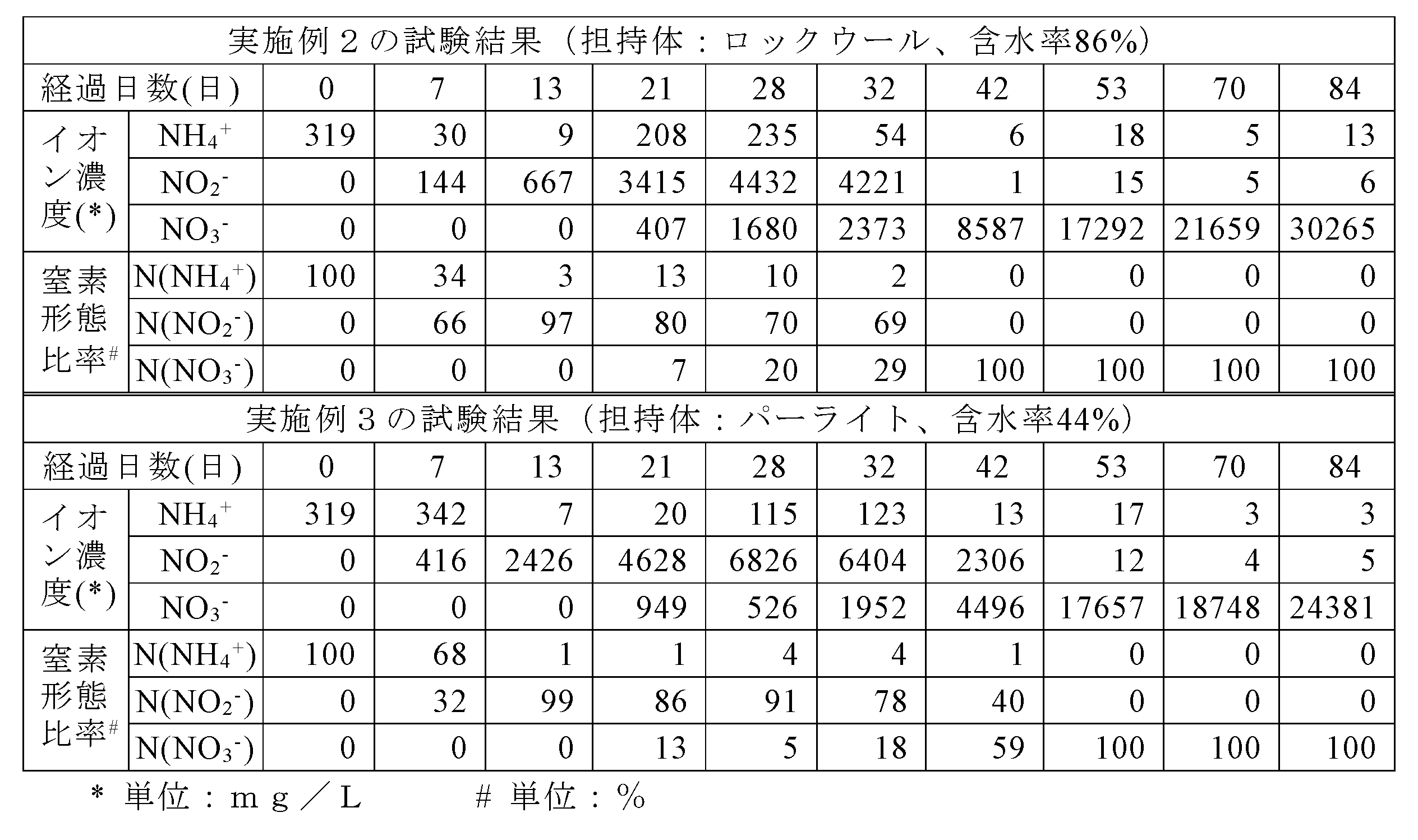
実施例4は、活性汚泥を32℃に2日間保持して種菌を培養し、アンモニア投入量を、窒素原子の質量換算で約380mg/日とした以外は、実施例1と同様の構成とし、同様な操作を行った。実施例5は、種菌として静岡県内の養豚場の活性汚泥槽より得られた活性汚泥を用い、32℃で8日間培養し、アンモニア投入量を、窒素原子の質量換算で約425mg/日とし、硝化菌担持体の温度を35℃に、循環水の温度を32℃にそれぞれ調整した以外は、実施例4と同様の構成及び操作を行った。なお、実施例5では、全微生物に対するAOB及びNOBの存在割合を、16S rRNAメタゲノム解析により分析した。
実施例4および5の試験結果を、表3に示す。
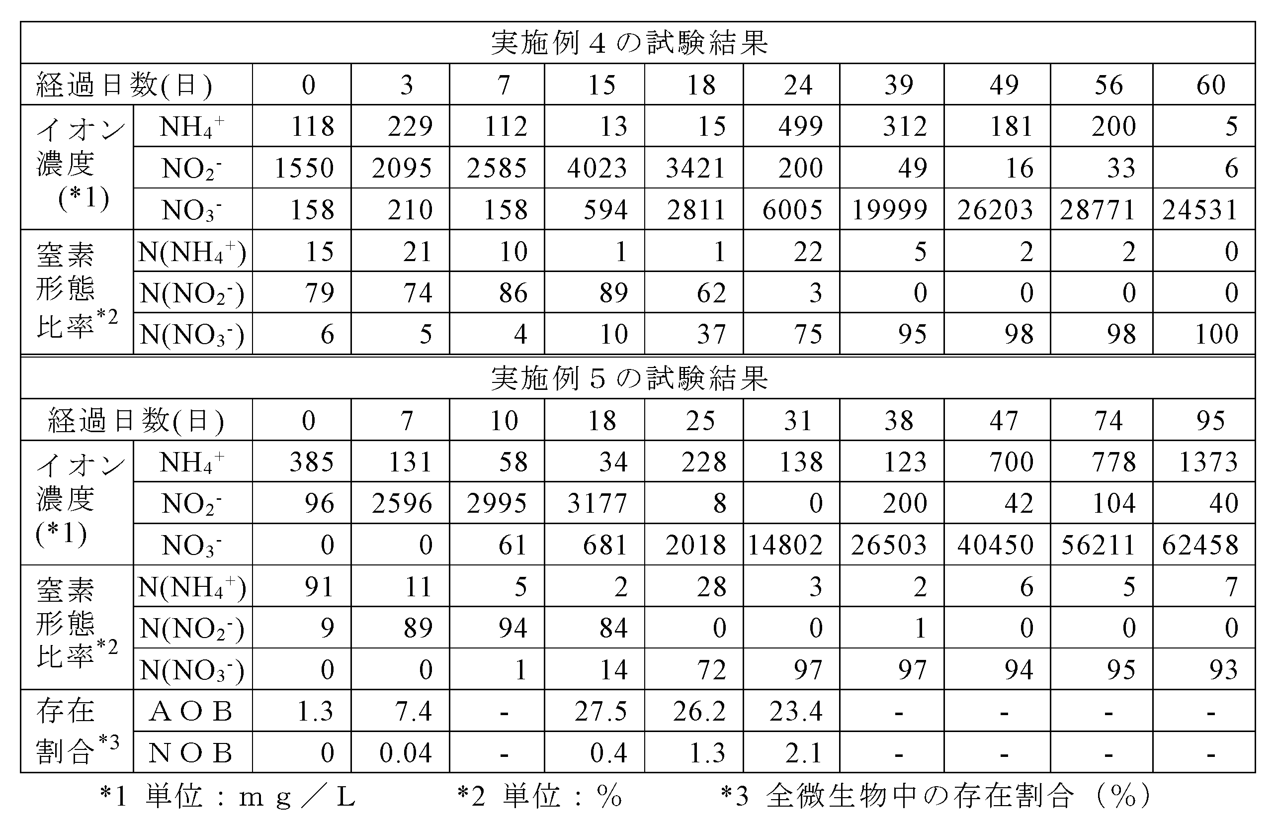
活性汚泥の培養日数を22日間とし、実施例1と同様の装置及び条件で150日以上運転した後に回収した水を1.2L混合して3Lの循環水として用い、かつ循環水の温度及びpHを調整せず(環境温度で)、エアレーションも行わずに、また、アンモニア投入量を、窒素原子の質量換算で約280mg/日とした以外は、実施例4と同様の操作を行った。試験結果を表4に示す。
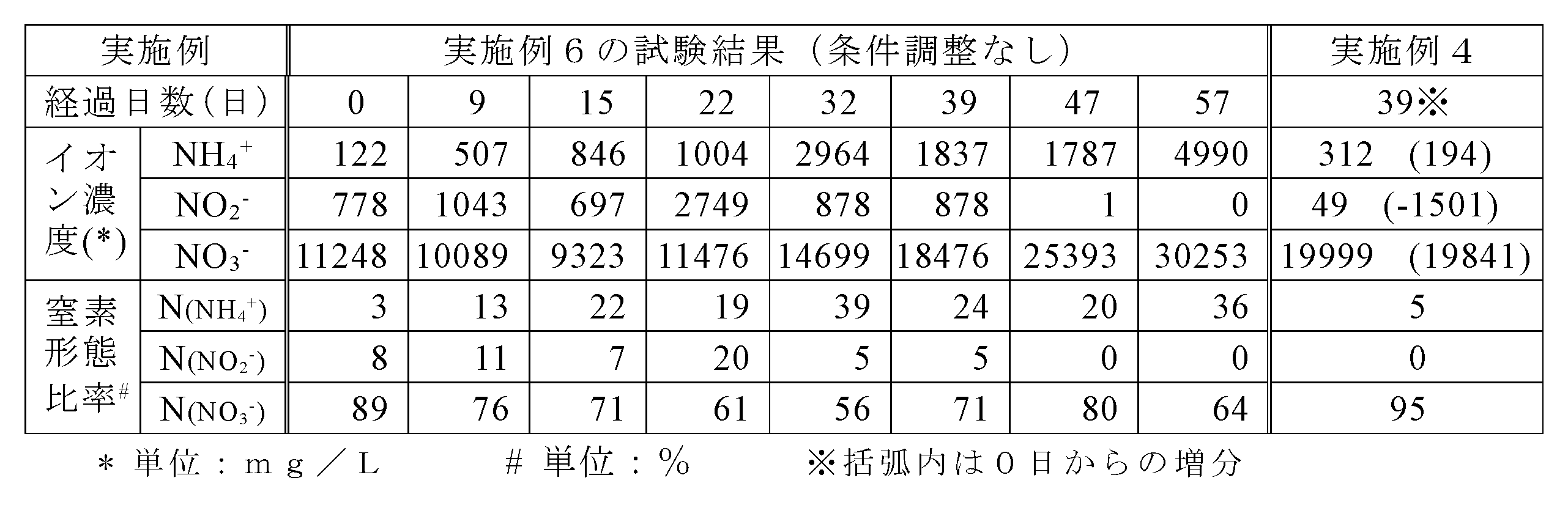
硝化菌担持体として、含水率を9%とした発泡ガラス((株)村上開明堂製、バブグラスG0001)を、種菌として他の実施例で使用した微生物をそれぞれ使用し、かつアンモニア投入量を、窒素原子の質量換算で約340mg/日として、実施例4と同様の構成とし、同様な操作を行った。微生物は、実施例1と同条件で100日以上運転した窒素回収装置で使用した発泡ガラスを循環水中に懸濁することにより、発泡ガラス表面から回収した。回収後の液3Lを、上記発泡ガラス0.9Lを備えた窒素回収装置に入れて12日間循環させ、微生物を発泡ガラスに馴染ませたのちに、循環水を10倍希釈した。それ以降は、実施例4と同様の構成及び操作を行い、各イオン濃度を測定した。結果を表5に示す。

実施例1と同条件で200日以上運転した窒素回収装置3台を使用し、その中の循環水10%を残した上でイオン交換水を加えて新規循環水の全量を2.8Lとし、そのpH下限値を6.5に調整しながら、アンモニアの投入量を(窒素原子の質量換算で)約200~300mg/日としたこと以外は、実施例1と同様の構成とし、同様の操作を行った。すなわち、既に活性汚泥(硝化菌)を担持した発泡ガラス(上記のバブグラスG0004、含水率30%)を用い、循環水のpHの下限値を6.5とした試験をn=3で行った(実施例8)。
実施例8の試験終了後の窒素回収装置3台を使用し、その中の循環水10%を残した上でイオン交換水を加えて新規循環水2.8Lとし、そのpHの下限値を6.0に調整しながら、実施例8と同様の試験を行った(実施例9)。
実施例9の試験終了後の窒素回収装置3台を使用し、循環水のpHの下限値を5.5に調整した以外は、実施例9と同様の試験を行った(実施例10)。
実施例10の試験終了後の窒素回収装置3台を使用し、循環水のpHの下限値を5.0に調整した以外は、実施例9及び10と同様の試験を行った(実施例11)。
各実施例の試験結果を、表6に示す。なお、表6中の数値は、n=3の平均値である。

実施例11の試験終了後の窒素回収装置3台を使用し、循環水2.8Lを新たに用いた上で、循環水の温度を20℃、pH下限値を7.0にそれぞれ調整し、一方で発泡ガラスの温度は調整せず、かつアンモニア投入量を、窒素原子の質量換算で約300mg/日とした以外は、実施例8と同様の試験を行った(実施例12)。
実施例12の試験終了後の窒素回収装置の内1台を使用し、循環水の温度を15℃に調整した以外は、実施例12と同様の試験を行った(実施例13)。
各実施例の試験結果を、表7に示す。
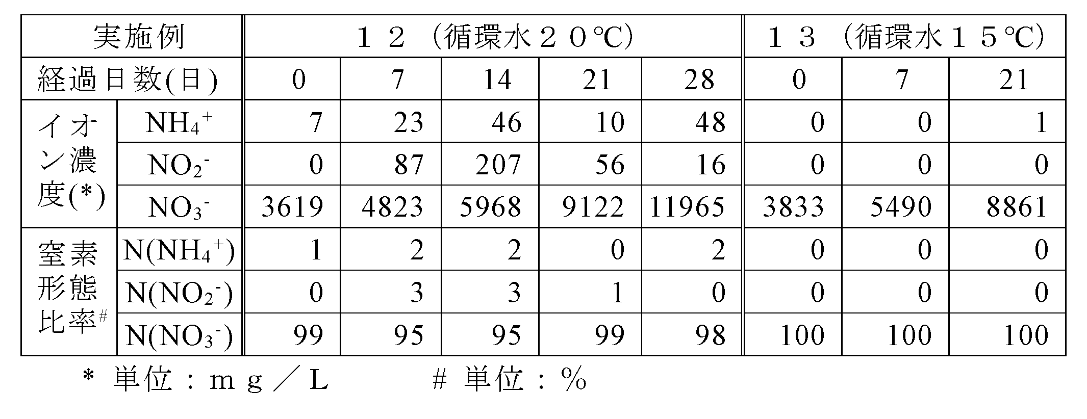
11 アンモニア含有ガス供給ライン
12 吸気ポンプ
20 微生物分解槽
21 硝化菌担持体
30 給水ライン
31 散水器
40 排水ライン
50 循環水貯留槽
60 循環ポンプ
70 再処理ライン
80 硝酸水溶液回収ライン
90 pHコントローラー
91 pHセンサ
100 pH調整剤供給ライン
101 アルカリ液槽
102 酸液槽
Claims (16)
- アンモニア含有ガス中のアンモニア成分を硝化菌で分解し、アンモニア含有の窒素成分をアンモニアガス分解生成物として回収する窒素回収方法であって、
硝化菌を担持した硝化菌担持体を保持してなる微生物分解槽に、循環水を供給して、前記硝化菌担持体を湿潤状態に保持し、
この湿潤状態とされた硝化菌担持体に、酸素存在雰囲気下でアンモニア含有ガスを通気し、
アンモニア含有ガス中のアンモニア成分および硝化菌により分解されたアンモニアガス分解生成物を、前記循環水中に溶解して、前記循環水中にアンモニアガス分解生成物を蓄積しながら、アンモニア含有ガスの分解処理を継続し、
前記循環水中におけるアンモニア分解生成物としての硝酸イオン濃度が5000mg/L以上にまで高められて所定濃度に達したとき、前記循環水の一部または全部をアンモニアガス分解生成物として回収することを特徴とする窒素回収方法。 - 硝化菌担持体が、無機多孔質体及び/又は無機繊維質体である請求項1に記載の窒素回収方法。
- 硝化菌担持体が、発泡ガラスである請求項1に記載の窒素回収方法。
- 微生物分解槽における硝化菌担持体の含水率を、5~90%とするものである請求項1~3のいずれかに記載の窒素回収方法。
- 微生物分解槽に供給される循環水は、硝化菌担持体の充填体積1L当りの水量が、50~50000mL/時間である請求項1~4のいずれかに記載の窒素回収方法。
- 前記循環水に対してエアレーションを行い、循環水1L当りのエアレーション量が0.5~10L/分である請求項1~5のいずれかに記載の窒素回収方法。
- 循環水はpHを5.0~9.0の範囲内、温度を10~60℃の範囲内に維持するものである請求項1~6のいずれかに記載の窒素回収方法。
- 硝化菌担持体に担持する硝化菌には、アンモニア酸化細菌群および亜硝酸酸化細菌群が含まれるものである請求項1~7のいずれかに記載の窒素回収方法。
- 前記循環水中におけるアンモニア分解生成物としての硝酸イオン濃度が5000mg/L以上にまで高められて所定濃度に達したとき、前記循環水の一部または全部をアンモニアガス分解生成物として回収した後、新たな循環水を系内に供給し、アンモニア含有ガスの分解処理を再開するものである請求項1~8のいずれかに記載の窒素回収方法。
- 請求項1~9のいずれかに記載の窒素回収方法において、前記循環水中における硝酸イオン濃度が、前記アンモニア含有ガスの通気を開始した時点の濃度から5000mg/L以上増加したとき、前記循環水の一部または全部をアンモニアガス分解生成物として回収する窒素回収方法。
- アンモニア含有ガス中のアンモニア成分を硝化菌で分解し、アンモニア含有の窒素成分をアンモニアガス分解生成物として回収する窒素回収装置であって、
(A) 硝化菌を担持した硝化菌担持体を有し、酸素存在雰囲気下で前記アンモニアガスを分解する微生物分解槽と、
(B) 前記微生物分解槽に前記アンモニア含有ガスを供給するアンモニア含有ガス供給手段と、
(C) 前記微生物分解槽に対して水を供給する給水手段と、
(D) 前記微生物分解槽において生成した前記アンモニアガス分解生成物を含む水を微生物分解槽より導出する排水ラインと、
(E) 前記排水ラインより排出された前記アンモニアガス分解生成物を含む水を一時的に貯留する貯留槽と、
(F) 前記貯留槽と前記微生物分解槽とを接続し、前記貯留槽より前記アンモニアガス分解生成物を含む水を前記微生物分解槽に送る再処理ラインと、
(G) 前記微生物分解槽、前記排水ライン、前記貯留槽、および前記再処理ラインの間で、前記アンモニアガス分解生成物を含む前記水を循環させる循環手段と、
(H) 前記貯留槽より、所定の硝酸イオン濃度となった前記アンモニアガス分解生成物を含む水の一部または全部を回収する回収手段と、を備える窒素回収装置。 - 硝化菌担持体が無機多孔質体及び/又は無機繊維質体である請求項11に記載の窒素回収装置。
- 硝化菌担持体が発泡ガラスである請求項11に記載の窒素回収装置。
- 前記微生物分解槽が、縦長形状を有し、下部側よりアンモニア含有ガスを供給し、上部側より水を供給する向流接触式のものとされている請求項11~13のいずれかに記載の窒素回収装置。
- 前記硝化菌が、アンモニア酸化細菌群および亜硝酸酸化細菌群を含むものである請求項11~14のいずれかに記載の窒素回収装置。
- 請求項1~10のいずれかに記載の窒素回収方法で回収されたアンモニアガス分解生成物を用いてなる製品。
Priority Applications (6)
| Application Number | Priority Date | Filing Date | Title |
|---|---|---|---|
| JP2021545610A JPWO2021049603A1 (ja) | 2019-09-13 | 2020-09-11 | |
| CN202080063846.3A CN114401782A (zh) | 2019-09-13 | 2020-09-11 | 氮回收方法、氮回收装置、及由其制得的产品 |
| EP20863910.4A EP4029825A4 (en) | 2019-09-13 | 2020-09-11 | METHOD FOR RECOVERING NITROGEN, DEVICE FOR RECOVERING NITROGEN AND PRODUCT PRODUCED THEREFROM |
| CA3154356A CA3154356A1 (en) | 2019-09-13 | 2020-09-11 | Nitrogen recovery method, nitrogen recovery device, and product obtained by same |
| US17/642,368 US20220323901A1 (en) | 2019-09-13 | 2020-09-11 | Nitrogen recovery method, nitrogen recovery device, and product obtained by same |
| KR1020227011962A KR20220066094A (ko) | 2019-09-13 | 2020-09-11 | 질소 회수 방법, 질소 회수 장치 및 이에 의해 얻어지는 제품 |
Applications Claiming Priority (2)
| Application Number | Priority Date | Filing Date | Title |
|---|---|---|---|
| JP2019166997 | 2019-09-13 | ||
| JP2019-166997 | 2019-09-13 |
Publications (1)
| Publication Number | Publication Date |
|---|---|
| WO2021049603A1 true WO2021049603A1 (ja) | 2021-03-18 |
Family
ID=74865728
Family Applications (1)
| Application Number | Title | Priority Date | Filing Date |
|---|---|---|---|
| PCT/JP2020/034429 WO2021049603A1 (ja) | 2019-09-13 | 2020-09-11 | 窒素回収方法、窒素回収装置、およびこれにより得られる製品 |
Country Status (8)
| Country | Link |
|---|---|
| US (1) | US20220323901A1 (ja) |
| EP (1) | EP4029825A4 (ja) |
| JP (1) | JPWO2021049603A1 (ja) |
| KR (1) | KR20220066094A (ja) |
| CN (1) | CN114401782A (ja) |
| CA (1) | CA3154356A1 (ja) |
| TW (1) | TW202116402A (ja) |
| WO (1) | WO2021049603A1 (ja) |
Cited By (2)
| Publication number | Priority date | Publication date | Assignee | Title |
|---|---|---|---|---|
| WO2022229589A3 (en) * | 2021-04-30 | 2022-12-15 | Treasure Holdings Ltd | A method of treating slurry |
| WO2023286090A1 (en) * | 2021-07-16 | 2023-01-19 | Atmonia Ehf. | Bioreactor system and process for nitrate production |
Citations (11)
| Publication number | Priority date | Publication date | Assignee | Title |
|---|---|---|---|---|
| JPS5742195B2 (ja) | 1977-12-30 | 1982-09-07 | ||
| JPH0724247A (ja) | 1993-07-09 | 1995-01-27 | Kubota Corp | 充填式生物脱臭塔の運転方法 |
| JP2000000600A (ja) | 1998-06-18 | 2000-01-07 | Kinki University | 大気汚染ガスを放出しない高含窒素汚泥処理システムおよび汚泥の処理方法 |
| JP2002153721A (ja) * | 2000-11-16 | 2002-05-28 | Ebara Corp | 堆肥化施設から発生する臭気ガスの処理方法と装置 |
| JP2004195440A (ja) * | 2002-12-20 | 2004-07-15 | Aisin Takaoka Ltd | 微生物脱臭装置 |
| JP2004358370A (ja) * | 2003-06-05 | 2004-12-24 | Jfe Engineering Kk | 生物脱臭用担体及びそれを用いた脱臭方法、脱臭装置 |
| JP2005161258A (ja) | 2003-12-04 | 2005-06-23 | Japan Steel Works Ltd:The | 高濃度アンモニア含有ガスの亜硝酸化方法およびその装置 |
| JP2008239466A (ja) * | 2007-03-29 | 2008-10-09 | Gunma Prefecture | 生物処理脱臭装置循環水を肥料に利用する方法と装置 |
| JP2011240254A (ja) | 2010-05-18 | 2011-12-01 | Ariake Japan Co Ltd | 含窒素有機廃棄物からのアンモニア生成と該アンモニアを肥効成分とした水耕栽培 |
| JP2014018779A (ja) * | 2012-07-23 | 2014-02-03 | National Agriculture & Food Research Organization | 脱臭装置 |
| JP2018130705A (ja) | 2017-02-17 | 2018-08-23 | 国立研究開発法人農業・食品産業技術総合研究機構 | 脱臭及び窒素除去方法 |
-
2020
- 2020-09-11 CA CA3154356A patent/CA3154356A1/en active Pending
- 2020-09-11 CN CN202080063846.3A patent/CN114401782A/zh active Pending
- 2020-09-11 WO PCT/JP2020/034429 patent/WO2021049603A1/ja unknown
- 2020-09-11 TW TW109131388A patent/TW202116402A/zh unknown
- 2020-09-11 US US17/642,368 patent/US20220323901A1/en active Pending
- 2020-09-11 JP JP2021545610A patent/JPWO2021049603A1/ja active Pending
- 2020-09-11 KR KR1020227011962A patent/KR20220066094A/ko unknown
- 2020-09-11 EP EP20863910.4A patent/EP4029825A4/en active Pending
Patent Citations (11)
| Publication number | Priority date | Publication date | Assignee | Title |
|---|---|---|---|---|
| JPS5742195B2 (ja) | 1977-12-30 | 1982-09-07 | ||
| JPH0724247A (ja) | 1993-07-09 | 1995-01-27 | Kubota Corp | 充填式生物脱臭塔の運転方法 |
| JP2000000600A (ja) | 1998-06-18 | 2000-01-07 | Kinki University | 大気汚染ガスを放出しない高含窒素汚泥処理システムおよび汚泥の処理方法 |
| JP2002153721A (ja) * | 2000-11-16 | 2002-05-28 | Ebara Corp | 堆肥化施設から発生する臭気ガスの処理方法と装置 |
| JP2004195440A (ja) * | 2002-12-20 | 2004-07-15 | Aisin Takaoka Ltd | 微生物脱臭装置 |
| JP2004358370A (ja) * | 2003-06-05 | 2004-12-24 | Jfe Engineering Kk | 生物脱臭用担体及びそれを用いた脱臭方法、脱臭装置 |
| JP2005161258A (ja) | 2003-12-04 | 2005-06-23 | Japan Steel Works Ltd:The | 高濃度アンモニア含有ガスの亜硝酸化方法およびその装置 |
| JP2008239466A (ja) * | 2007-03-29 | 2008-10-09 | Gunma Prefecture | 生物処理脱臭装置循環水を肥料に利用する方法と装置 |
| JP2011240254A (ja) | 2010-05-18 | 2011-12-01 | Ariake Japan Co Ltd | 含窒素有機廃棄物からのアンモニア生成と該アンモニアを肥効成分とした水耕栽培 |
| JP2014018779A (ja) * | 2012-07-23 | 2014-02-03 | National Agriculture & Food Research Organization | 脱臭装置 |
| JP2018130705A (ja) | 2017-02-17 | 2018-08-23 | 国立研究開発法人農業・食品産業技術総合研究機構 | 脱臭及び窒素除去方法 |
Non-Patent Citations (2)
| Title |
|---|
| JUHLER S., REVSBECH N. P., SCHRAMM A., HERRMANN M., OTTOSEN L. D. M. AND NIELSEN L. P.: "Distribution and rate of microbial processes in ammonia-loaded air filter biofilm", APPL. ENVIRON. MICROBIOL., vol. 75, 2009, pages 3705 - 3713 |
| KRUEMMELAND HEINZ: "Effect of organic matter on growth and cell yield of ammonia-oxidizing bacteria", ARCH. MICROBIOL., vol. 133, 1982, pages 50 - 54 |
Cited By (2)
| Publication number | Priority date | Publication date | Assignee | Title |
|---|---|---|---|---|
| WO2022229589A3 (en) * | 2021-04-30 | 2022-12-15 | Treasure Holdings Ltd | A method of treating slurry |
| WO2023286090A1 (en) * | 2021-07-16 | 2023-01-19 | Atmonia Ehf. | Bioreactor system and process for nitrate production |
Also Published As
| Publication number | Publication date |
|---|---|
| JPWO2021049603A1 (ja) | 2021-03-18 |
| KR20220066094A (ko) | 2022-05-23 |
| EP4029825A1 (en) | 2022-07-20 |
| EP4029825A4 (en) | 2023-10-11 |
| CN114401782A (zh) | 2022-04-26 |
| CA3154356A1 (en) | 2021-03-18 |
| US20220323901A1 (en) | 2022-10-13 |
| TW202116402A (zh) | 2021-05-01 |
Similar Documents
| Publication | Publication Date | Title |
|---|---|---|
| KR101451598B1 (ko) | 전처리부 및 후처리부가 연속설치된 친환경 바이오필터식 탈취장치 및 이를 이용한 탈취방법 | |
| WO2021049603A1 (ja) | 窒素回収方法、窒素回収装置、およびこれにより得られる製品 | |
| Chung et al. | Biotreatment of hydrogen sulfide-and ammonia-containing waste gases by fluidized bed bioreactor | |
| JP2638721B2 (ja) | 生物学的脱臭方法 | |
| CN110465184A (zh) | 除臭填料及其制备方法、除臭装置和除臭方法及应用 | |
| KR101061690B1 (ko) | 액비 제조 균주 공급이 가능한 탈취 시스템 및 이를 구비한 액비화 장치 | |
| CN111960871A (zh) | 用于减少畜禽粪便堆肥过程氨挥发的原位固氮剂及其应用 | |
| JP6935900B2 (ja) | 脱臭及び窒素除去方法 | |
| Nakasaki et al. | Effect of bulking agent on the reduction of NH3emissions during thermophilic composting of night-soil sludge | |
| JP2008534243A (ja) | 換気空気からアンモニア、臭気及び粉塵を除去する方法並びにこのような方法に使用する装置 | |
| KR100524647B1 (ko) | 바이오필터를 이용한 악취 제거장치 및 방법 | |
| Kanagawa et al. | Biological treatment of ammonia gas at high loading | |
| WO2022210685A1 (ja) | 硝化菌製剤 | |
| JP2002233729A (ja) | 悪臭ガスの脱臭方法および脱臭装置 | |
| KR100991403B1 (ko) | 악취 저감 오폐수 처리 시설 및 그 방법 | |
| JP3447537B2 (ja) | 微生物脱臭装置および該装置の運転方法 | |
| JP6765780B2 (ja) | 脱臭装置 | |
| JP4026256B2 (ja) | 生物脱臭装置の馴養方法 | |
| KR100481287B1 (ko) | 질석을 이용한 악취제거장치 및 방법 | |
| JP2003117341A (ja) | アンモニア含有ガスの処理方法及びその装置 | |
| JP2002153721A (ja) | 堆肥化施設から発生する臭気ガスの処理方法と装置 | |
| Komariah et al. | Design of Biofiltration System for Ammonia Removal from the Storage of Rubber Processed Materials | |
| JP3910308B2 (ja) | 悪臭ガスの脱臭方法及び脱臭装置 | |
| JP2005022928A (ja) | コンポスト製造装置及びコンポストの製造方法 | |
| JPH07155534A (ja) | 消臭装置 |
Legal Events
| Date | Code | Title | Description |
|---|---|---|---|
| 121 | Ep: the epo has been informed by wipo that ep was designated in this application |
Ref document number: 20863910 Country of ref document: EP Kind code of ref document: A1 |
|
| ENP | Entry into the national phase |
Ref document number: 2021545610 Country of ref document: JP Kind code of ref document: A |
|
| ENP | Entry into the national phase |
Ref document number: 3154356 Country of ref document: CA |
|
| NENP | Non-entry into the national phase |
Ref country code: DE |
|
| ENP | Entry into the national phase |
Ref document number: 20227011962 Country of ref document: KR Kind code of ref document: A |
|
| ENP | Entry into the national phase |
Ref document number: 2020863910 Country of ref document: EP Effective date: 20220413 |