WO2021049501A1 - 温度推定装置 - Google Patents
温度推定装置 Download PDFInfo
- Publication number
- WO2021049501A1 WO2021049501A1 PCT/JP2020/034018 JP2020034018W WO2021049501A1 WO 2021049501 A1 WO2021049501 A1 WO 2021049501A1 JP 2020034018 W JP2020034018 W JP 2020034018W WO 2021049501 A1 WO2021049501 A1 WO 2021049501A1
- Authority
- WO
- WIPO (PCT)
- Prior art keywords
- temperature
- estimation
- time
- initial value
- estimated
- Prior art date
- Legal status (The legal status is an assumption and is not a legal conclusion. Google has not performed a legal analysis and makes no representation as to the accuracy of the status listed.)
- Ceased
Links
Images


Classifications
-
- G—PHYSICS
- G01—MEASURING; TESTING
- G01K—MEASURING TEMPERATURE; MEASURING QUANTITY OF HEAT; THERMALLY-SENSITIVE ELEMENTS NOT OTHERWISE PROVIDED FOR
- G01K3/00—Thermometers giving results other than momentary value of temperature
- G01K3/005—Circuits arrangements for indicating a predetermined temperature
-
- B—PERFORMING OPERATIONS; TRANSPORTING
- B60—VEHICLES IN GENERAL
- B60L—PROPULSION OF ELECTRICALLY-PROPELLED VEHICLES; SUPPLYING ELECTRIC POWER FOR AUXILIARY EQUIPMENT OF ELECTRICALLY-PROPELLED VEHICLES; ELECTRODYNAMIC BRAKE SYSTEMS FOR VEHICLES IN GENERAL; MAGNETIC SUSPENSION OR LEVITATION FOR VEHICLES; MONITORING OPERATING VARIABLES OF ELECTRICALLY-PROPELLED VEHICLES; ELECTRIC SAFETY DEVICES FOR ELECTRICALLY-PROPELLED VEHICLES
- B60L3/00—Electric devices on electrically-propelled vehicles for safety purposes; Monitoring operating variables, e.g. speed, deceleration or energy consumption
-
- G—PHYSICS
- G01—MEASURING; TESTING
- G01K—MEASURING TEMPERATURE; MEASURING QUANTITY OF HEAT; THERMALLY-SENSITIVE ELEMENTS NOT OTHERWISE PROVIDED FOR
- G01K13/00—Thermometers specially adapted for specific purposes
-
- G—PHYSICS
- G01—MEASURING; TESTING
- G01K—MEASURING TEMPERATURE; MEASURING QUANTITY OF HEAT; THERMALLY-SENSITIVE ELEMENTS NOT OTHERWISE PROVIDED FOR
- G01K7/00—Measuring temperature based on the use of electric or magnetic elements directly sensitive to heat ; Power supply therefor, e.g. using thermoelectric elements
- G01K7/42—Circuits effecting compensation of thermal inertia; Circuits for predicting the stationary value of a temperature
-
- H—ELECTRICITY
- H02—GENERATION; CONVERSION OR DISTRIBUTION OF ELECTRIC POWER
- H02M—APPARATUS FOR CONVERSION BETWEEN AC AND AC, BETWEEN AC AND DC, OR BETWEEN DC AND DC, AND FOR USE WITH MAINS OR SIMILAR POWER SUPPLY SYSTEMS; CONVERSION OF DC OR AC INPUT POWER INTO SURGE OUTPUT POWER; CONTROL OR REGULATION THEREOF
- H02M7/00—Conversion of AC power input into DC power output; Conversion of DC power input into AC power output
- H02M7/42—Conversion of DC power input into AC power output without possibility of reversal
- H02M7/44—Conversion of DC power input into AC power output without possibility of reversal by static converters
- H02M7/48—Conversion of DC power input into AC power output without possibility of reversal by static converters using discharge tubes with control electrode or semiconductor devices with control electrode
-
- H—ELECTRICITY
- H02—GENERATION; CONVERSION OR DISTRIBUTION OF ELECTRIC POWER
- H02P—CONTROL OR REGULATION OF ELECTRIC MOTORS, ELECTRIC GENERATORS OR DYNAMO-ELECTRIC CONVERTERS; CONTROLLING TRANSFORMERS, REACTORS OR CHOKE COILS
- H02P29/00—Arrangements for regulating or controlling electric motors, appropriate for both AC and DC motors
- H02P29/60—Controlling or determining the temperature of the motor or of the drive
-
- Y—GENERAL TAGGING OF NEW TECHNOLOGICAL DEVELOPMENTS; GENERAL TAGGING OF CROSS-SECTIONAL TECHNOLOGIES SPANNING OVER SEVERAL SECTIONS OF THE IPC; TECHNICAL SUBJECTS COVERED BY FORMER USPC CROSS-REFERENCE ART COLLECTIONS [XRACs] AND DIGESTS
- Y02—TECHNOLOGIES OR APPLICATIONS FOR MITIGATION OR ADAPTATION AGAINST CLIMATE CHANGE
- Y02T—CLIMATE CHANGE MITIGATION TECHNOLOGIES RELATED TO TRANSPORTATION
- Y02T10/00—Road transport of goods or passengers
- Y02T10/60—Other road transportation technologies with climate change mitigation effect
- Y02T10/64—Electric machine technologies in electromobility
Definitions
- the present disclosure relates to a temperature estimation device that is applied to a system including a storage battery and a power converter electrically connected to the storage battery, and estimates the temperature of components constituting the system.
- an in-vehicle system including a storage battery, an inverter connected to the storage battery, a rotary electric machine, and a cable connecting the rotary electric machine and the inverter is known.
- an electric current flows through the cable to drive the rotary electric machine, the cable generates heat.
- the temperature of the cable may exceed its permissible upper limit.
- the estimation accuracy of the cable temperature may decrease. In particular, the accuracy of estimating the cable temperature immediately after driving the rotary electric machine may decrease.
- the initial value of the cable temperature is set to a value equal to, for example, the ambient temperature of the cable.
- the estimated cable temperature may be lower than the actual temperature of the cable under the condition that the current flows through the cable thereafter. As a result, the actual temperature of the cable exceeds the allowable upper limit value, and there is a concern that the cable may be overheated.
- the temperature estimation target is not limited to cables.
- power is transmitted between the power converter and the power storage device by the operation of the power converter among the components constituting the system. If the component that raises the temperature when the temperature is raised is a temperature estimation target, the above-mentioned problems can occur as well.
- the main object of the present disclosure is to provide a temperature estimation device capable of improving the temperature estimation accuracy of the component to be estimated.
- the present disclosure applies to a system comprising a power storage device and a power converter electrically connected to the power storage device.
- the temperature at which the temperature of the estimated target component which is a component that raises the temperature when power is transmitted between the power converter and the power storage device by the operation of the power converter, is estimated.
- An initial value estimation unit that estimates the initial temperature value of the component to be estimated at the start of operation of the power converter, and an initial value estimation unit.
- a change amount estimation unit that estimates the temperature change amount of the estimation target component based on the current value supplied from the power converter by the operation of the power converter. It is provided with a temperature estimation unit that calculates the estimated temperature of the component to be estimated based on the initial temperature value and the amount of temperature change.
- the initial value estimation unit estimates the initial temperature value based on the elapsed time from the previous instruction to stop the temperature estimation of the estimation target component to the current instruction to start the temperature estimation of the estimation target component. ..
- the initial temperature value of the component to be estimated is estimated at the start of operation of the power converter. Then, the amount of temperature change of the component to be estimated is estimated based on the current value supplied from the power converter as the power converter operates. Then, the estimated temperature of the component to be estimated is calculated based on the estimated initial temperature value and the amount of temperature change.
- the elapsed time from the previous instruction to stop the temperature estimation of the estimation target component to the current instruction to start the temperature estimation of the estimation target component greatly affects the estimation accuracy of the initial temperature value.
- the initial temperature value is estimated based on the elapsed time. Therefore, the temperature estimation accuracy of the estimation target component can be improved.
- FIG. 1 is an overall configuration diagram of an in-vehicle system according to the first embodiment.
- FIG. 2 is a flowchart showing the procedure of the temperature estimation process.
- FIG. 3 is a flowchart showing the procedure of the initial value estimation process.
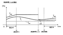
- FIG. 4 is a time chart showing an initial value estimation method when the elapsed time is short.
- FIG. 5 is a time chart showing an initial value estimation method when the elapsed time is long.
- FIG. 6 is a flowchart showing the procedure of the initial value estimation process according to the second embodiment.
- FIG. 7 is a time chart showing the initial value estimation method.
- FIG. 8 is a time chart showing an initial value estimation method when the elapsed time is medium.
- FIG. 9 is a flowchart showing the procedure of the initial value estimation process according to the third embodiment.
- FIG. 10 is a flowchart showing the procedure of the initial value estimation process according to the fourth embodiment.
- FIG. 11 is a time chart showing an initial value estimation method when the elapsed time is long.
- FIG. 12 is a flowchart showing the procedure of the initial value estimation process according to the fifth embodiment.
- FIG. 13 is a flowchart showing the procedure of the initial value estimation process according to the sixth embodiment.
- the temperature estimation device of the present embodiment constitutes a system mounted on a hybrid vehicle or an electric vehicle.
- the vehicle 10 includes a rotary electric machine 20, an inverter 30 as a power converter, and a storage battery 40 as a power storage device.
- the rotary electric machine 20 is, for example, a star-shaped brushless synchronous machine.
- the rotor of the rotary electric machine 20 is capable of transmitting power to the drive wheels of the vehicle 10. As a result, the rotary electric machine 20 becomes a traveling power source for the vehicle 10.
- the storage battery 40 is a rechargeable and dischargeable secondary battery, specifically, for example, a lithium ion storage battery or a nickel hydrogen storage battery.
- the storage battery 40 serves as a power supply source for the rotary electric machine 20 when the rotary electric machine 20 functions as an electric motor, and stores the generated power when the rotary electric machine 20 functions as a generator.
- the inverter 30 includes a switch SW for the upper and lower arms for the number of phases (three phases) and a capacitor 31 for smoothing.
- the switch SW is, for example, a voltage-controlled semiconductor switching element, specifically an N-channel MOSFET or an IGBT. In each phase, the connection points of the switches SW of the upper and lower arms are connected to the connector portion 32 of the inverter 30.
- Vehicle 10 is equipped with an AC cable 33 for three phases.
- the first end of the AC cable 33 is connected to the connector portion 32 of the inverter 30, and the second end of the AC cable 33 is connected to the connector portion 21 of the rotary electric machine 20.
- the connector portion 21 of the rotary electric machine 20 is connected to the stator winding of the rotary electric machine 20.
- the vehicle 10 is provided with a relay 35 that connects the storage battery 40 and the inverter 30.
- a relay 35 that connects the storage battery 40 and the inverter 30.
- the vehicle 10 is provided with a charger 50 as a power converter.
- the charging connector portion 51 of the charger 50 can be connected to the power supply equipment 60 provided outside the vehicle 10 via the charging cable 61.
- the charger 50 converts the AC power supplied from the power supply facility 60 via the charging cable 61 and the charging connector section 51 into DC power and supplies the AC power to the storage battery 40. As a result, the storage battery 40 is charged.
- a relay is also provided between the storage battery 40 and the charger 50, but the relay is not shown in FIG.
- the vehicle 10 is provided with a cooling device 70 for cooling the inverter 30.
- the cooling device 70 includes a cooling water passage through which a cooling fluid (cooling water) for cooling the inverter 30 flows, a pump for circulating cooling water in the passage, and a pump for blowing air to the inverter 30 for cooling. Including with fans.
- the rotary electric machine 20, the inverter 30, the AC cable 33, the relay 35, the storage battery 40, and the charger 50 are arranged in the motor room, which is a predetermined equipment arrangement space provided in the vehicle 10.
- the motor room is provided in front of the driver's seat in, for example, the vehicle 10.
- the vehicle 10 includes a phase current sensor 80 and an ambient temperature sensor 81.
- the phase current sensor 80 detects the phase current flowing through the AC cable 33.
- the phase current sensor 80 for example, a non-contact type having a current transformer is used.
- the ambient temperature sensor 81 detects the temperature inside the motor room as the ambient temperature Tmr.
- the ambient temperature sensor 81 detects the temperature around the AC cable 33 in the motor room as the ambient temperature Tmr.
- the detected values of the phase current sensor 80 and the ambient temperature sensor 81 and the operating state of the cooling device 70 are input to the electronic control device (ECU 90) provided in the vehicle 10.
- ECU 90 electronice control device
- the ECU 90 is mainly composed of a microcomputer, operates a relay 35, operates each switch SW of the inverter 30 to control the torque of the rotary electric machine 20 to a command torque, and charges the charger 50 to charge the storage battery 40. To operate. In the present embodiment, the storage battery 40 is charged while the vehicle 10 is stopped. Further, the function provided by the ECU 90 can be provided by, for example, software recorded in a physical memory device, a computer for executing the software, hardware, or a combination thereof.
- the ECU 90 performs a temperature estimation process for estimating the temperature of the components of the in-vehicle system.
- the temperature estimation target by the processing is the AC cable 33.
- the ECU 90 performs temperature estimation processing for a period from the determination that the temperature estimation start instruction has been made to the determination that the temperature estimation stop instruction has been made, and after determining that the temperature estimation stop instruction has been given, the temperature estimation The temperature estimation process is stopped for a period until it is determined that the start instruction has been given.
- the ECU 90 determines that the temperature estimation start instruction has been given. Further, when the ECU 90 determines that the drive stop instruction of the rotary electric machine 20 has been given, it determines that the temperature estimation stop instruction has been given. Therefore, no current flows through the AC cable 33 during the period from the temperature estimation stop instruction to the temperature estimation start instruction.
- the ECU 90 may determine, for example, that the drive permission has been granted when it is determined that the relay 35 has been switched on, and that the drive stop instruction has been given when it has determined that the relay 35 has been switched off. ..
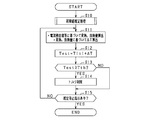
- FIG. 2 shows the procedure of the temperature estimation process. This process is executed with the determination that the temperature estimation start instruction of the AC cable 33 has been made as a trigger.
- step S10 an initial value estimation process for estimating the initial temperature value Tini of the AC cable 33 is performed. This process will be described in detail later.
- the process of step S10 corresponds to the initial value estimation unit.
- steps S11 to S15 are executed.
- the processes of steps S11 to S15 are repeatedly executed in a predetermined control cycle.
- step S11 the temperature change amount ⁇ T of the AC cable 33 after the temperature estimation start instruction is given is determined based on the current value detected by the phase current sensor 80 and the ambient temperature Tmr detected by the ambient temperature sensor 81. calculate. Specifically, the temperature change amount ⁇ T is calculated based on the heat generation amount of the AC cable 33 and the heat dissipation amount from the AC cable 33. The amount of heat generated may be calculated based on the current value detected by the phase current sensor 80 and the amount of heat received from the heat-generating components around the AC cable 33. Further, the heat dissipation amount may be calculated based on the temperature difference between the estimated temperature Test and the ambient temperature Tmr, and the heat dissipation amount of the AC cable 33 by the cooling device 70.
- the amount of heat radiated by the cooling device 70 includes the amount of heat radiated by the wind hitting the AC cable 33 by the fan and the amount of heat radiated by the cooling water circulated by the pump.
- the process of step S11 corresponds to the change amount estimation unit.
- step S12 the estimated temperature test (n) of the AC cable 33 in the current control cycle is calculated by adding the temperature change amount ⁇ T estimated in step S11 to the initial temperature value Tini estimated in step S10.
- the process in step S12 corresponds to the temperature estimation unit.
- step S13 it is determined whether or not the estimated temperature Test calculated in step S12 is equal to or higher than the threshold temperature Tth.
- step S13 If an affirmative judgment is made in step S13, the process proceeds to step S14, and the command torque is limited by the upper limit value. As a result, an increase in the current flowing through the AC cable 33 (specifically, the amplitude of the AC current) is suppressed, and the AC cable 33 is prevented from becoming overheated.
- step S14 If the process of step S14 is completed, or if a negative determination is made in step S13, the process proceeds to step S15 to determine whether or not the temperature estimation stop instruction has been given. If it is determined that the temperature estimation stop instruction has not been given, the process proceeds to step S11. On the other hand, when it is determined that the temperature estimation stop instruction has been given, the temperature estimation process is stopped.
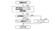
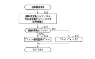
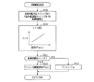
- FIG. 3 shows the procedure of the initial value estimation process in step S10.
- step S20 the elapsed time from the timing when the temperature estimation stop instruction was given last time to the timing when the temperature estimation start instruction was given this time is calculated.
- step S21 it is determined whether or not the elapsed time calculated in step S20 is less than the specified time Lth.
- the specified time Lth may be set to, for example, the time required for the temperature of the AC cable 33 to reach the temperature of the motor room. More specifically, for example, the specified time Lth is the range in which the temperature of the AC cable 33 can be taken when the temperature of the motor room is maintained at the same temperature as the upper limit of the range in which the temperature of the motor room can be taken. It may be set to the time required from the same temperature as the upper limit value of to reach the temperature of the motor room.
- the specified time Lth is, for example, a value predetermined by an experiment, numerical calculation, or the like.
- step S21 If an affirmative judgment is made in step S21, the process proceeds to step S22, and the estimated temperature test calculated immediately before the timing when the temperature estimation stop instruction is given last time is set as the initial temperature value Tini.
- step S21 the process proceeds to step S23, and the specified temperature T ⁇ is set to the initial temperature value Tini. That is, the initial temperature value Tini is reset to the specified temperature T ⁇ .
- the specified temperature T ⁇ is set to the upper limit value (for example, 85 ° C.) of the range in which the temperature of the AC cable 33 can be taken at the timing when the specified time Lth has elapsed from the timing when the temperature estimation stop instruction was previously given. There is.
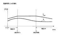
- Tr indicates the actual temperature of the AC cable 33.
- the temperature estimation stop instruction is given, so the temperature estimation process is stopped.
- the temperature estimation start instruction is given, so that the temperature estimation process is restarted.
- the estimated temperature Test at the time t1 is used as the initial temperature value Tini.
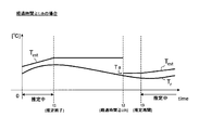
- the temperature estimation stop instruction is given at time t1, the temperature estimation process is stopped. After that, at time t3, the temperature estimation start instruction is given, so that the temperature estimation process is restarted. Since the elapsed time represented by the times t1 to t3 is equal to or longer than the specified time Lth, the specified temperature T ⁇ is used as the initial temperature value Tini. In FIG. 5, for convenience of explanation, the estimated temperature Test is reset and changed at time t2, but in reality, the estimation process is stopped during the period from time t1 to t3.
- the initial temperature value Tini of the AC cable 33 is estimated at the start of operation of the inverter 30. Then, the temperature change amount ⁇ T of the AC cable 33 is estimated based on the current detection value of the phase current sensor 80 during the operation of the inverter 30. Then, the temperature test of the AC cable 33 is estimated based on the estimated initial temperature value Tini and the temperature change amount ⁇ T.
- the estimated temperature Test calculated in 1 is set as the initial temperature value Tini.
- the specified temperature T ⁇ is set as the initial temperature value Tini.
- the estimated temperature test of the AC cable 33 can be prevented from becoming excessively high with respect to the actual temperature of the AC cable 33, or the vehicle 10 can be stopped for a short time. In this case, it is possible to prevent the estimated temperature test of the AC cable 33 from becoming excessively low with respect to the actual temperature of the AC cable 33.
- the specified temperature T ⁇ is set to the upper limit of the range in which the temperature of the AC cable 33 can be taken at the timing when the specified time Lth has elapsed from the timing when the temperature estimation stop instruction was last issued.
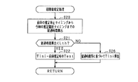
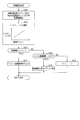
- FIG. 6 shows the procedure of the initial value estimation process according to the present embodiment.
- the same processing as that shown in FIG. 3 is designated by the same reference numerals for convenience.
- step S20 After the completion of step S20, the process proceeds to step S24, and it is determined whether or not the calculated elapsed time is less than the first specified time Lth1. If an affirmative determination is made in step S21, the process proceeds to step S22.
- step S24 the process proceeds to step S25, and whether or not the calculated elapsed time is equal to or greater than the first specified time Lth1 and less than the second specified time Lth2 (> Lth1) is determined. judge.
- the second specified time Lth2 is set to, for example, the same time as the specified time Lth described in the first embodiment. If it is determined in step S25 that the elapsed time exceeds the second specified time Lth2, the process proceeds to step S23.
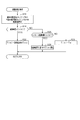
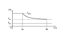
- step S25 the process proceeds to step S26, and the value at which the estimated temperature test calculated immediately before the temperature estimation stop instruction is given last time is monotonically decreased in relation to the elapsed time is the initial temperature value Tini. Estimate as. Hereinafter, the method of estimating the initial temperature value Tini in step S26 will be described with reference to FIG. 7.
- ta indicates the timing when the temperature estimation stop instruction was given last time
- tb indicates the timing when the temperature estimation start instruction was given this time
- Tend indicates the estimation immediately before the timing when the temperature estimation stop instruction was given last time.
- tb-ta is the elapsed time calculated in step S20.
- the initial temperature value Tini is estimated using the following equation (eq1), the elapsed time calculated in step S20, the ambient temperature Tmr, and the stop temperature Tend.
- the above equation (eq1) is an estimation equation in which the stop temperature Tend gradually approaches the ambient temperature Tmr according to the elapsed time.
- the time constant ⁇ on the right side of the above equation (eq1) is a value adapted by, for example, an experiment or a numerical calculation, and is set to 1 to 2 hours.
- the time constant ⁇ may be set based on, for example, the time required for the temperature of the AC cable 33 to reach the temperature of the motor room. More specifically, for example, the time constant ⁇ is the range in which the temperature of the AC cable 33 can be taken when the temperature of the motor room is maintained at the same temperature as the upper limit of the range in which the temperature of the motor room can be taken. It may be set based on the time required to reach the temperature of the motor room from the same temperature as the upper limit value of.
- the temperature estimation stop instruction is given at time t1, the temperature estimation process is stopped. After that, at time t2, the temperature estimation start instruction is given, so that the temperature estimation process is started.
- the initial temperature value Tini at time t2 is a value corresponding to the elapsed time represented by times t1 to t2, as described with reference to FIG. In FIG. 8, for convenience of explanation, the estimated temperature test changes at times t1 to t2, but the estimation process is actually stopped during the period from t1 to t2.
- FIG. 9 shows the procedure of the initial value estimation process according to the present embodiment. In the present embodiment, if a negative determination is made in step S21, the process proceeds to step S26. In FIG. 9, the same processes as those shown in FIGS. 3 and 6 are designated by the same reference numerals for convenience.
- FIG. 10 shows the procedure of the initial value estimation process according to the present embodiment.
- the same processes as those shown in FIG. 3 above are designated by the same reference numerals for convenience.
- step S21 If a negative determination is made in step S21, the process proceeds to step S27, and the initial temperature value Tini is estimated based on the ambient temperature Tmr detected by the ambient temperature sensor 81.
- the temperature of the motor room is set to a value equal to or less than the upper limit of the possible range and higher than the ambient temperature Tmr at the initial temperature. Estimate the value Tini.
- the temperature estimation stop instruction is given at time t1, the temperature estimation process is stopped. After that, at time t3, the temperature estimation start instruction is given, so that the temperature estimation process is started.
- the initial temperature value Tini at time t3 is a value obtained by adding a predetermined offset amount ⁇ C to the ambient temperature Tmr.
- the estimated temperature Test changes at time t2, but the estimation process is actually stopped during the period from t1 to t3.
- the cooling water temperature detected by the water temperature sensor is used as the ambient temperature Tmr in step S27.
- the temperature estimation target may be the capacitor 31.
- the initial temperature value of the capacitor 31 arranged at a position closer to the position where the cooling water flows than the AC cable 33 is the upper limit value (for example, 85 ° C.) of the range in which the temperature of the motor room can be taken and the cooling water temperature. It may be estimated as an average value (for example, 65 ° C.) with (for example, 45 ° C.).
- FIG. 12 shows the procedure of the initial value estimation process according to the present embodiment.
- the same processes as those shown in FIG. 3 above are designated by the same reference numerals for convenience.
- step S20 the process proceeds to step S28, and the higher the estimated temperature test (Tend of stop temperature in the second embodiment) calculated immediately before the timing when the temperature estimation stop instruction is given last time, the more the specified time Lth is set. Set longer. Specifically, for example, when the estimated temperature test calculated immediately before the timing when the temperature estimation stop instruction is given last time is higher than the specified temperature T ⁇ , the higher the estimated temperature test, the longer the specified time Lth is set.
- step S28 when the estimated temperature test is low, the estimated temperature test is reset to the specified temperature T ⁇ at an early stage, and when the estimated temperature test is high, the reset of the estimated temperature test is delayed.
- the initial temperature value Tini can be prevented from becoming lower than the actual temperature of the AC cable 33.
- FIG. 13 shows the procedure of the initial value estimation process according to the present embodiment.
- the same processing as that shown in FIG. 6 is designated by the same reference numerals for convenience.
- step S20 the process proceeds to step S29, and the higher the estimated temperature test calculated immediately before the timing when the temperature estimation stop instruction is given last time, the longer the first specified time Lth1 and the second specified time Lth2 are set. .. Specifically, for example, when the estimated temperature test calculated immediately before the timing when the temperature estimation stop instruction is given last time is higher than the specified temperature T ⁇ , the higher the estimated temperature test, the more the first specified time Lth1 and the second specified time. Set Lth2 longer.
- step S23 in FIG. 6 may be changed to the process of step S27 in FIG.
- step S12 the temperature change amount ⁇ T calculated in step S11 is added to the estimated temperature test (n-1) calculated in the previous control cycle, so that the estimated temperature test in the current control cycle is added. (N) may be calculated.
- the ambient temperature sensor 81 may detect, for example, the ambient temperature of the vehicle 10 as the ambient temperature Tmr as long as the temperature has a correlation with the temperature of the motor room. Further, the ambient temperature Tmr used in the temperature estimation process is not limited to the detection value of the sensor, and may be an estimated value estimated by a predetermined process.
- the electric path connecting the inverter 30 and the rotary electric machine 20 may be a bus bar instead of the AC cable 33.
- the temperature estimation target by the temperature estimation process may be the bus bar.
- the temperature estimation target is not limited to the AC cable 33.
- it may be a capacitor 31, a connector portion 32 of the inverter 30, or a connector portion 21 of the rotary electric machine 20. ..
- the temperature estimation target is not limited to the AC cable 33, and may be, for example, the phase current sensor 80 or the charging connector portion 51 of the charger 50.
- the ECU 90 is used when the ECU 90 start instruction is given this time.
- the initial temperature value Tini may be estimated based on the elapsed time from the previous stop instruction to the start instruction of the ECU 90 this time.
- This estimation method is, for example, a method in which the ECU 90 is operating while the rotary electric machine 20 maintains the drive stop state. Specifically, for example, an estimation method during charging of the storage battery 40 using the power supply equipment 60. Is.
- the initial temperature value of the charging connector portion 51 of the charger 50 can be estimated appropriately, and by extension, the temperature estimation accuracy of the charging connector portion 51 during charging can be improved.
- the temperature estimation target is the charging connector section 51
- the temperature change amount ⁇ T is, for example, the detection value of the power supply current sensor that detects the current flowing through the storage battery 40, or the charging current value transmitted from the power supply facility 60. It may be calculated based on this.
- the number of temperature estimation targets is not limited to one, and may be multiple.
- the controls and methods thereof described in the present disclosure are provided by a dedicated computer provided by configuring a processor and memory programmed to perform one or more functions embodied by a computer program. It may be realized. Alternatively, the controls and methods thereof described in the present disclosure may be implemented by a dedicated computer provided by configuring the processor with one or more dedicated hardware logic circuits. Alternatively, the control unit and method thereof described in the present disclosure may be a combination of a processor and memory programmed to perform one or more functions and a processor composed of one or more hardware logic circuits. It may be realized by one or more dedicated computers configured. Further, the computer program may be stored in a computer-readable non-transitional tangible recording medium as an instruction executed by the computer.
Landscapes
- Engineering & Computer Science (AREA)
- Physics & Mathematics (AREA)
- General Physics & Mathematics (AREA)
- Power Engineering (AREA)
- Sustainable Energy (AREA)
- Sustainable Development (AREA)
- Life Sciences & Earth Sciences (AREA)
- Transportation (AREA)
- Mechanical Engineering (AREA)
- Electric Propulsion And Braking For Vehicles (AREA)
- Control Of Electric Motors In General (AREA)
- Power Conversion In General (AREA)
- Inverter Devices (AREA)
Priority Applications (1)
| Application Number | Priority Date | Filing Date | Title |
|---|---|---|---|
| US17/692,691 US12253421B2 (en) | 2019-09-12 | 2022-03-11 | Temperature estimation device |
Applications Claiming Priority (2)
| Application Number | Priority Date | Filing Date | Title |
|---|---|---|---|
| JP2019-166514 | 2019-09-12 | ||
| JP2019166514A JP7207243B2 (ja) | 2019-09-12 | 2019-09-12 | 温度推定装置 |
Related Child Applications (1)
| Application Number | Title | Priority Date | Filing Date |
|---|---|---|---|
| US17/692,691 Continuation US12253421B2 (en) | 2019-09-12 | 2022-03-11 | Temperature estimation device |
Publications (1)
| Publication Number | Publication Date |
|---|---|
| WO2021049501A1 true WO2021049501A1 (ja) | 2021-03-18 |
Family
ID=74862117
Family Applications (1)
| Application Number | Title | Priority Date | Filing Date |
|---|---|---|---|
| PCT/JP2020/034018 Ceased WO2021049501A1 (ja) | 2019-09-12 | 2020-09-08 | 温度推定装置 |
Country Status (3)
| Country | Link |
|---|---|
| US (1) | US12253421B2 (enExample) |
| JP (1) | JP7207243B2 (enExample) |
| WO (1) | WO2021049501A1 (enExample) |
Families Citing this family (5)
| Publication number | Priority date | Publication date | Assignee | Title |
|---|---|---|---|---|
| JP7229280B2 (ja) * | 2021-01-19 | 2023-02-27 | Semitec株式会社 | 温度測定装置、体温計、温度測定方法及び温度減衰測定方法 |
| FR3148087B1 (fr) * | 2023-04-21 | 2025-03-21 | Valeo Eautomotive Germany Gmbh | Procédé de détermination de la température d'un composant d'un onduleur de puissance |
| US12296693B2 (en) | 2023-07-12 | 2025-05-13 | GM Global Technology Operations LLC | System and method for temperature estimation of inverter AC power bus |
| US12391390B2 (en) * | 2023-09-25 | 2025-08-19 | Pratt & Whitney Canada Corp. | System and method for identifying a high-temperature condition of an electrical cable for an aircraft propulsion system |
| WO2025195819A1 (de) * | 2024-03-21 | 2025-09-25 | Robert Bosch Gmbh | Verfahren, recheneinheit und computerprogramm zum ermitteln einer temperatur zumindest eines elektrischen leiters und elektrisches antriebssystem |
Citations (3)
| Publication number | Priority date | Publication date | Assignee | Title |
|---|---|---|---|---|
| JP2017057973A (ja) * | 2015-09-18 | 2017-03-23 | 株式会社デンソー | シフトレンジ切替制御装置 |
| JP2017073898A (ja) * | 2015-10-07 | 2017-04-13 | 株式会社デンソー | 電動機制御装置 |
| JP2020088911A (ja) * | 2018-11-15 | 2020-06-04 | トヨタ自動車株式会社 | 自動車用のセンサシステム |
Family Cites Families (5)
| Publication number | Priority date | Publication date | Assignee | Title |
|---|---|---|---|---|
| JP4343898B2 (ja) * | 2005-12-15 | 2009-10-14 | 三菱電機株式会社 | 回転電機の温度推定装置 |
| JP4624400B2 (ja) | 2007-11-19 | 2011-02-02 | 株式会社オートネットワーク技術研究所 | 車両用の電線保護方法および電線保護装置 |
| JP5786452B2 (ja) | 2011-05-20 | 2015-09-30 | トヨタ自動車株式会社 | 高圧ケーブル保護システム |
| JP6508024B2 (ja) * | 2015-12-10 | 2019-05-08 | 株式会社デンソー | 電力変換装置 |
| JP6980077B1 (ja) * | 2020-10-22 | 2021-12-15 | 三菱電機株式会社 | 回転電機の制御装置 |
-
2019
- 2019-09-12 JP JP2019166514A patent/JP7207243B2/ja active Active
-
2020
- 2020-09-08 WO PCT/JP2020/034018 patent/WO2021049501A1/ja not_active Ceased
-
2022
- 2022-03-11 US US17/692,691 patent/US12253421B2/en active Active
Patent Citations (3)
| Publication number | Priority date | Publication date | Assignee | Title |
|---|---|---|---|---|
| JP2017057973A (ja) * | 2015-09-18 | 2017-03-23 | 株式会社デンソー | シフトレンジ切替制御装置 |
| JP2017073898A (ja) * | 2015-10-07 | 2017-04-13 | 株式会社デンソー | 電動機制御装置 |
| JP2020088911A (ja) * | 2018-11-15 | 2020-06-04 | トヨタ自動車株式会社 | 自動車用のセンサシステム |
Also Published As
| Publication number | Publication date |
|---|---|
| US12253421B2 (en) | 2025-03-18 |
| JP2021044983A (ja) | 2021-03-18 |
| US20220196483A1 (en) | 2022-06-23 |
| JP7207243B2 (ja) | 2023-01-18 |
Similar Documents
| Publication | Publication Date | Title |
|---|---|---|
| JP7207243B2 (ja) | 温度推定装置 | |
| CN108134558B (zh) | 电动机系统的控制装置及温度检测状态判定方法 | |
| JP5761117B2 (ja) | 回転機の制御装置 | |
| EP2706657B1 (en) | Brushless motor control apparatus and brushless motor control method | |
| US11400917B2 (en) | Power supply system for vehicle | |
| US11043830B2 (en) | Vehicle and electric power control device for vehicle | |
| US8736234B2 (en) | Power converter control apparatus | |
| KR101664039B1 (ko) | 구동 모터의 온도 추정 시스템 및 방법 | |
| JP6683116B2 (ja) | モータ制御装置 | |
| TWI492518B (zh) | 一種電動機之輸出控制裝置及控制器之控制方法 | |
| JP2017108546A (ja) | 電力変換装置 | |
| US12101050B2 (en) | Cooling control device | |
| JP6531706B2 (ja) | 回転電機の制御装置 | |
| JP7142719B2 (ja) | モータ制御装置 | |
| JP5303295B2 (ja) | 車両用電力変換装置および電動車両 | |
| JP6756277B2 (ja) | 回転電機ユニット | |
| JP7467194B2 (ja) | 駆動装置、および、駆動装置の制御方法 | |
| JP2015137084A (ja) | ハイブリッド車両の制御装置 | |
| JP7451260B2 (ja) | 駆動装置、および、駆動装置の制御方法 | |
| US12199543B2 (en) | Motor driving method, apparatus, and system | |
| JP7484672B2 (ja) | 車両のモータ制御システム、および、車両のモータ制御方法 | |
| JP2025080579A (ja) | 電池昇温装置 | |
| JP6398682B2 (ja) | 電流推定装置 | |
| CN121219952A (zh) | 用于确定电源逆变器的部件的温度的方法 | |
| JP2017195719A (ja) | 回転電機の制御装置 |
Legal Events
| Date | Code | Title | Description |
|---|---|---|---|
| 121 | Ep: the epo has been informed by wipo that ep was designated in this application |
Ref document number: 20863898 Country of ref document: EP Kind code of ref document: A1 |
|
| NENP | Non-entry into the national phase |
Ref country code: DE |
|
| 122 | Ep: pct application non-entry in european phase |
Ref document number: 20863898 Country of ref document: EP Kind code of ref document: A1 |