WO2021039605A1 - 画像形成装置 - Google Patents
画像形成装置 Download PDFInfo
- Publication number
- WO2021039605A1 WO2021039605A1 PCT/JP2020/031533 JP2020031533W WO2021039605A1 WO 2021039605 A1 WO2021039605 A1 WO 2021039605A1 JP 2020031533 W JP2020031533 W JP 2020031533W WO 2021039605 A1 WO2021039605 A1 WO 2021039605A1
- Authority
- WO
- WIPO (PCT)
- Prior art keywords
- image data
- image
- document
- control unit
- reading
- Prior art date
Links
Images


Classifications
-
- H—ELECTRICITY
- H04—ELECTRIC COMMUNICATION TECHNIQUE
- H04N—PICTORIAL COMMUNICATION, e.g. TELEVISION
- H04N1/00—Scanning, transmission or reproduction of documents or the like, e.g. facsimile transmission; Details thereof
- H04N1/00681—Detecting the presence, position or size of a sheet or correcting its position before scanning
- H04N1/00684—Object of the detection
- H04N1/00702—Position
-
- H—ELECTRICITY
- H04—ELECTRIC COMMUNICATION TECHNIQUE
- H04N—PICTORIAL COMMUNICATION, e.g. TELEVISION
- H04N1/00—Scanning, transmission or reproduction of documents or the like, e.g. facsimile transmission; Details thereof
-
- H—ELECTRICITY
- H04—ELECTRIC COMMUNICATION TECHNIQUE
- H04N—PICTORIAL COMMUNICATION, e.g. TELEVISION
- H04N1/00—Scanning, transmission or reproduction of documents or the like, e.g. facsimile transmission; Details thereof
- H04N1/0035—User-machine interface; Control console
- H04N1/00405—Output means
- H04N1/00408—Display of information to the user, e.g. menus
- H04N1/0044—Display of information to the user, e.g. menus for image preview or review, e.g. to help the user position a sheet
-
- H—ELECTRICITY
- H04—ELECTRIC COMMUNICATION TECHNIQUE
- H04N—PICTORIAL COMMUNICATION, e.g. TELEVISION
- H04N1/00—Scanning, transmission or reproduction of documents or the like, e.g. facsimile transmission; Details thereof
- H04N1/00681—Detecting the presence, position or size of a sheet or correcting its position before scanning
- H04N1/00684—Object of the detection
- H04N1/00708—Size or dimensions
-
- H—ELECTRICITY
- H04—ELECTRIC COMMUNICATION TECHNIQUE
- H04N—PICTORIAL COMMUNICATION, e.g. TELEVISION
- H04N1/00—Scanning, transmission or reproduction of documents or the like, e.g. facsimile transmission; Details thereof
- H04N1/00795—Reading arrangements
- H04N1/00798—Circuits or arrangements for the control thereof, e.g. using a programmed control device or according to a measured quantity
- H04N1/00801—Circuits or arrangements for the control thereof, e.g. using a programmed control device or according to a measured quantity according to characteristics of the original
-
- H—ELECTRICITY
- H04—ELECTRIC COMMUNICATION TECHNIQUE
- H04N—PICTORIAL COMMUNICATION, e.g. TELEVISION
- H04N1/00—Scanning, transmission or reproduction of documents or the like, e.g. facsimile transmission; Details thereof
- H04N1/00795—Reading arrangements
- H04N1/00798—Circuits or arrangements for the control thereof, e.g. using a programmed control device or according to a measured quantity
- H04N1/00811—Circuits or arrangements for the control thereof, e.g. using a programmed control device or according to a measured quantity according to user specified instructions, e.g. user selection of reading mode
-
- H—ELECTRICITY
- H04—ELECTRIC COMMUNICATION TECHNIQUE
- H04N—PICTORIAL COMMUNICATION, e.g. TELEVISION
- H04N1/00—Scanning, transmission or reproduction of documents or the like, e.g. facsimile transmission; Details thereof
- H04N1/00795—Reading arrangements
- H04N1/00798—Circuits or arrangements for the control thereof, e.g. using a programmed control device or according to a measured quantity
- H04N1/00814—Circuits or arrangements for the control thereof, e.g. using a programmed control device or according to a measured quantity according to a detected condition or state of the reading apparatus, e.g. temperature
-
- H—ELECTRICITY
- H04—ELECTRIC COMMUNICATION TECHNIQUE
- H04N—PICTORIAL COMMUNICATION, e.g. TELEVISION
- H04N1/00—Scanning, transmission or reproduction of documents or the like, e.g. facsimile transmission; Details thereof
- H04N1/00795—Reading arrangements
- H04N1/00798—Circuits or arrangements for the control thereof, e.g. using a programmed control device or according to a measured quantity
- H04N1/00816—Determining the reading area, e.g. eliminating reading of margins
-
- H—ELECTRICITY
- H04—ELECTRIC COMMUNICATION TECHNIQUE
- H04N—PICTORIAL COMMUNICATION, e.g. TELEVISION
- H04N1/00—Scanning, transmission or reproduction of documents or the like, e.g. facsimile transmission; Details thereof
- H04N1/04—Scanning arrangements, i.e. arrangements for the displacement of active reading or reproducing elements relative to the original or reproducing medium, or vice versa
-
- H—ELECTRICITY
- H04—ELECTRIC COMMUNICATION TECHNIQUE
- H04N—PICTORIAL COMMUNICATION, e.g. TELEVISION
- H04N2201/00—Indexing scheme relating to scanning, transmission or reproduction of documents or the like, and to details thereof
- H04N2201/0077—Types of the still picture apparatus
- H04N2201/0094—Multifunctional device, i.e. a device capable of all of reading, reproducing, copying, facsimile transception, file transception
Definitions
- the present invention relates to an image forming apparatus capable of reading a document.
- the image forming apparatus capable of reading the original is provided with an image reading unit.
- the image reading unit reads a range set by the user (see, for example, Patent Document 1).
- Some image forming devices read the original set on the contact glass.
- Such an image forming apparatus reads a reading range set by the user in the contact glass on which the original is set.
- the size of the original set on the contact glass varies.
- Standard size (for example, A4 size) originals may be set on the contact glass, and irregular size originals such as driver's licenses, health insurance cards and business cards (card originals smaller than the standard size) may be placed on the contact glass. It may be set.
- the user sets the scanning range to A4 size when the document to be read is a card document having a size smaller than A4 size.
- the user sets the card document within the range corresponding to the A4 size of the contact glass.
- the image forming apparatus sets the range corresponding to the A4 size of the contact glass in which the card document is set as the reading range, and reads the set reading range. Then, the image forming apparatus outputs the image data of the read area (the area corresponding to the reading range).
- the image data output from the image forming apparatus includes image data in the document area (the area of the contact glass where the card document exists), but in the area outside the document (the area of the contact glass where the card document does not exist). Image data is also included. Therefore, it is not convenient for users who want to output only the image data of the card manuscript.
- the present invention has been made to solve the above problems, and an object of the present invention is to provide an image forming apparatus capable of outputting image data of a region desired by a user among image data obtained by reading. To do.
- the image forming apparatus of the present invention reads an operation panel that displays an image and accepts operations from the user, an output unit that outputs data to an external device, and a contact glass in which a document is set. It is provided with an image reading unit that performs normal reading that generates first image data that is image data of the read region, and a control unit that performs output data selection processing.
- the control unit extracts the second image data, which is the image data of the original, from the first image data.
- the control unit displays the first preview image corresponding to the first image data and the second preview image corresponding to the second image data on the operation panel, and displays either the first preview image or the second preview image.
- the operation panel accept the selection operation to be selected.
- the control unit causes the output unit to output the first image data.
- the control unit causes the output unit to output the second image data.
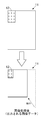
- Schematic diagram showing the configuration of the multifunction device according to the embodiment of the present invention The schematic diagram which shows the structure of the image reading part of the multifunction device by one Embodiment of this invention Top view showing the contact glass of the multifunction device according to one embodiment of the present invention. The figure which shows the state at the time of opening and closing of the document cover of the multifunction device by one Embodiment of this invention.
- the figure for demonstrating the image data output when the transmission job is executed without using the output data selection function mounted on the multifunction device according to one Embodiment of this invention The figure for demonstrating the image data output when the transmission job is executed without using the output data selection function mounted on the multifunction device according to one Embodiment of this invention.
- the figure for demonstrating the preview image displayed by the operation panel of the multifunction device according to one Embodiment of this invention The figure for demonstrating the preview image displayed by the operation panel of the multifunction device according to one Embodiment of this invention.
- the figure for demonstrating the preview image displayed by the operation panel of the multifunction device according to one Embodiment of this invention The figure which shows the state which the document set on the contact glass of the multifunction device by one Embodiment of this invention is out of a reading range.
- the multifunction device 100 of the present embodiment includes an image reading unit 1 and a printing unit 2.
- the multifunction device 100 corresponds to an "image forming apparatus".
- the image reading unit 1 includes a contact glass 10.
- the contact glass 10 is installed above the housing 101 of the image reading unit 1.
- the upper surface of the contact glass 10 is the set surface 10S on which the document D is set.
- the image reading unit 1 reads the contact glass 10 and generates image data of the read region.
- the document D is set on the set surface 10S
- the document D set on the set surface 10S is read.
- the set surface 10S has a rectangular shape that is long in the left-right direction of the multifunction device 100 in a plan view.
- a pair of short sides are parallel to the main scanning direction (front-rear direction of the multifunction device 100)
- a pair of long sides are parallel to the sub-scanning direction (direction orthogonal to the main scanning direction). And become parallel.
- FIG. 3 illustrates an example in which the position of the upper left corner of the set surface 10S is set to the reference position RP.
- the image reading unit 1 starts reading from the reading start line SL.
- the reading start line SL is a line along the first reference side RS1. Therefore, when the document D is set on the set surface 10S, the user aligns a certain corner of the document D with the reference position RP. Further, of the four sides of the document D, one side is aligned with the first reference side RS1 and the other side is aligned with the second reference side RS2.
- a document cover 102 is installed in the housing 101.
- the document cover 102 opens and closes with respect to the set surface 10S.
- a rotating shaft 103 is provided at the rear portion of the housing 101.
- the document cover 102 is rotatably supported by the rotation shaft 103.
- the document cover 102 rotates so that the front portion is a free end and the front portion is shaken in the vertical direction.
- the document cover 102 can be opened and closed with respect to the set surface 10S by lifting or lowering the front portion of the document cover 102 in the vertical direction.
- the document cover 102 When the document cover 102 is opened, the set surface 10S is exposed, and the document D can be set on the set surface 10S (see the upper diagram of FIG. 4).
- the document cover 102 When the document cover 102 is closed, the set surface 10S is covered by the document cover 102 (see the lower diagram of FIG. 4).
- the document D When the document D is set on the set surface 10S, the user opens the document cover 102. After setting the document D on the set surface 102, the user closes the document cover 102.
- the document cover 102 When the document cover 102 is closed, the document D on the set surface 10S is pressed by the document cover 102.
- the image reading unit 1 includes a light source 11, an image sensor 12, a mirror 13, and a lens 14. Each member of the image reading unit 1 is housed inside the housing 101.
- the light source 11 has a plurality of LED elements (not shown).
- the plurality of LED elements are arranged in the main scanning direction (direction perpendicular to the paper surface of FIG. 2).
- the light source 11 irradiates light toward the contact glass 10.
- the light from the light source 11 passes through the contact glass 10. In the region where the document D is set, the light from the light source 11 is reflected by the document D.
- the image sensor 12 has a plurality of photoelectric conversion elements arranged in the main scanning direction.
- the image sensor 12 receives the light reflected by the document D.
- the image sensor 12 performs photoelectric conversion on a line-by-line basis for each pixel to accumulate electric charges, and outputs a signal corresponding to the accumulated electric charges.
- the mirror 13 reflects the light reflected by the document D toward the lens 14.
- the lens 14 collects the light reflected by the mirror 13 and guides it to the image sensor 12.
- the light source 11 and the mirror 13 are installed on the carriage 15 that can move in the sub-scanning direction.
- the carriage 15 is connected to the wire 16.
- the wire 16 is wound around the take-up drum 17. When the take-up drum 17 rotates, the carriage 15 moves in the sub-scanning direction. That is, the light source 11 and the mirror 13 move in the sub-scanning direction.
- the carriage 15 moves in the sub-scanning direction (direction from left to right when viewed from the front).
- the light source 11 irradiates the contact glass 10 with light.
- the image sensor 12 repeatedly performs photoelectric conversion of the reflected light reflected by the document D. As a result, the document D is read in line units.
- the printing unit 2 includes a paper transport path 20.
- the paper transport path 20 is shown by a broken line.
- the printing unit 2 prints an image on the paper P transported along the paper transport path 20.
- the printing unit 2 prints the image on the paper P based on the image data obtained by reading by the image reading unit 1.
- the printing unit 2 includes a paper feeding unit 21, an image forming unit 22, and a fixing unit 23.
- the paper feed unit 21 feeds the paper P into the paper transport path 20.
- the image forming unit 22 forms a toner image (image), and transfers (prints) the toner image onto the paper P being conveyed.
- the fixing unit 23 heats and pressurizes the paper P being conveyed. As a result, the toner image is fixed on the paper P.
- the multifunction device 100 includes an operation panel 3.
- the operation panel 3 is provided with a touch screen 31.
- the touch screen 31 displays a screen including software buttons, and accepts a touch operation on the display screen (software button) from the user.
- a hardware button 32 is also provided on the operation panel 3.
- the number of hardware buttons 32 installed is plural.
- the hardware button 32 includes a start button for accepting a start operation requesting a job accompanied by reading by the image reading unit 1 from the user.
- the multifunction device 100 includes a control unit 4 and a storage unit 5.
- the control unit 4 includes a CPU.
- the storage unit 5 includes a ROM and a RAM.
- the storage unit 5 is connected to the control unit 4.
- the storage unit 5 stores the control program and control data.
- the control unit 4 controls each unit of the multifunction device 100 based on the control program and the control data.
- the image reading unit 1, the printing unit 2, and the operation panel 3 are connected to the control unit 4.
- the control unit 4 controls the reading operation of the image reading unit 1 and also controls the printing operation of the printing unit 2. Further, the control unit 4 controls the display operation of the operation panel 3 and detects the operation performed on the operation panel 3.
- a cover sensor CS is connected to the control unit 4.
- the cover sensor CS is a sensor for detecting the opening / closing of the document cover 102.
- an optical sensor having a light emitting unit and a light receiving unit is used.
- the cover sensor CS detects an actuator (not shown) that can move in the vertical direction between the light emitting unit and the light receiving unit.
- the actuator is provided in the housing 101. The actuator is always urged upwards.
- the actuator When the document cover 102 is completely closed (see the figure below in FIG. 4), the actuator is pressed downward by the document cover 102. At this time, the optical path (the region between the light emitting portion and the light receiving portion) of the cover sensor CS is shielded by the actuator. On the other hand, when the document cover 102 is completely opened (see the upper figure of FIG. 4), the pressure on the actuator by the document cover 102 is released. At this time, the optical path of the cover sensor CS is open.
- the document cover 101 transitions from the opened state to the closed state, the document cover 102 comes into contact with the actuator, and the actuator moves downward. Then, when the document cover 102 is closed until the tilt angle of the document cover 102 (the angle between the set surface 10S) becomes a predetermined angle, the optical path of the cover sensor CS is blocked by the actuator. At this time, the output value of the cover sensor CS changes.
- the control unit 4 monitors the output value of the cover sensor CS.
- the control unit 4 detects the opening / closing of the document cover CS based on the output value of the cover sensor CS. Further, the control unit 4 detects that the tilt angle of the opened document cover 102 has reached a predetermined angle based on the output value of the cover sensor CS.
- the user opens the document cover 102 and sets the document on the setting surface 10S. After that, the user closes the document cover 102.
- the user opens the document cover 102 and extracts the document D from the set surface 10S. After that, the user closes the document cover 102.
- the document cover 102 is opened and closed before the start of the job and after the completion of the job. That is, the control unit 4 detects that the tilt angle of the opened document cover 102 has reached a predetermined angle before the start of the job and after the completion of the job.
- the multifunction device 100 is provided with a network communication unit 61.
- the network communication unit 61 is an interface for connecting the multifunction device 100 to a network NT such as the Internet.
- the network communication unit 61 includes a LAN communication circuit.
- the network communication unit 61 is connected to the wireless LAN access point.
- the control unit 4 controls the network communication unit 61 and communicates with an external device connected to the network NT.
- an external device connected to the network NT there is a PC201 (personal computer) used by a user of the multifunction device 100.
- PC201 personal computer
- By connecting the PC 201 to the multifunction device 100 it is possible to execute a transmission job for transmitting image data from the multifunction device 100 to the PC 201.
- the image data obtained by reading by the image reading unit 1 can be transmitted to the PC 201.
- the multifunction device 100 is provided with a USB interface unit 62.
- the USB interface unit 62 is an interface for connecting an external device to the multifunction device 100 via USB.
- a USB device 202 such as a USB memory can be connected to the multifunction device 100.
- the USB interface unit 62 includes a USB communication circuit.
- the control unit 4 controls the USB interface unit 62 and communicates with the USB device 202 connected to the multifunction device 100.
- the control unit 4 writes the information to the USB device 202 and reads the information from the USB device 202.
- By connecting the USB device 202 to the multifunction device 100 it is possible to execute a transmission job for transmitting image data from the multifunction device 100 to the USB device 202.
- the image data obtained by reading by the image reading unit 1 can be transmitted to the USB device 202.
- the network communication unit 61 and the USB interface unit 62 correspond to the "output unit".
- the network communication unit 61 and the USB interface unit 62 are collectively referred to as an output unit 6.
- the PC 201 and the USB device 202 are generally referred to as an external device 200.
- the control unit 4 causes the output unit 6 to output image data to the external device 200.
- the image data obtained by reading by the image reading unit 1 is transmitted from the multifunction device 100 to the external device 200.
- the external device 200 stores the image data received from the multifunction device 100.
- the operation panel 3 accepts the settings related to the transmission job.
- the control unit 4 sets the reading range by the image reading unit 1 based on the set value of the setting item "original size”. Further, the control unit 4 performs image processing on the image data obtained by reading by the image reading unit 1 based on the set value of the setting item “transmission size” and the set value of the setting item “zoom”.
- a card document CD having an irregular size is set on the set surface 10S as the document D to be read when the transmission job is executed.
- the card manuscript CD is, for example, an ID card such as a driver's license, a health insurance card, and a business card.
- the card manuscript CD is shown by a dot pattern.
- the range corresponding to A4 size which is one of the standard sizes, is surrounded by a broken line.
- the setting value of the setting item "original size” is set to A4 size
- the setting value of the setting item “transmission size” is set to A4 size (the same size as the original size)
- the control unit 4 sets the range corresponding to the A4 size (the range surrounded by the broken line in FIG. 3), which is the set value of the setting item "original size", as the reading range of the image reading unit 1. Further, the control unit 4 causes the image reading unit 1 to read the set scanning range (the scanning range set based on the set value of the setting item “original size”). The image reading unit 1 reads the set reading range and generates image data of the reading area (the area corresponding to the set reading range).
- the set reading range is a range corresponding to the A4 size
- the image data in the reading area includes the image data of the card original CD.
- the image data in the reading area corresponds to the "first image data”
- the image data of the card manuscript CD corresponds to the "second image data”.
- the image data in the reading region is referred to as the first image data and is designated by reference numeral 11.
- the image data of the card manuscript CD is referred to as the second image data and is designated by reference numeral 12.
- the image data as shown in the upper figure of FIG. 6 is generated as the first image data 11.
- the first image data 11 includes the second image data 12.
- the second image data 12 is shown by a dot pattern. The same applies to the drawings referred to in the following description.
- control unit 4 After the generation of the first image data 11, the control unit 4 performs various image processing on the first image data 11. For example, density conversion processing, data format conversion processing, and the like are performed as image processing. Further, the control unit 4 performs a process of adjusting the size of the first image data 11 (width in the main scanning direction and width in the sub-scanning direction) to the size indicated by the set value of the setting item “transmission size”.
- the setting value of the setting item "transmission size” is A4 size
- the setting value of the setting item "zoom” is 100%. Therefore, the size of the first image data 11 is set to A4 size. Further, the first image data 11 is not enlarged or reduced.
- the first image data 11 after image processing is shown in the lower figure of FIG.
- control unit 4 After the image processing on the first image data 11, the control unit 4 causes the output unit 6 to output the first image data 11 after the image processing.
- the first image data 11 shown in the lower figure of FIG. 6 is output.
- the operation panel 3 accepts the output destination setting from the user.
- the control unit 4 controls the network communication unit 61 and transmits the first image data 11 after the image processing to the PC 201.
- the control unit 4 controls the USB interface unit 62 and transmits the first image data 11 after image processing to the USB device 202.
- the setting value of the setting item "original size” is set to A4 size
- the setting value of the setting item "transmission size” is set to A5 size
- the setting value of the setting item "zoom” is automatic. Suppose it is set to.
- the reading range of the image reading unit 1 is set to the range corresponding to the A4 size. Then, the image reading unit 1 reads the set reading range. As a result, as shown in the upper figure of FIG. 7, the first image data 11 including the second image data 12 (the same first image data 11 as in the first example) is generated.
- control unit 4 performs image processing on the first image data 11.
- the control unit 4 performs image processing on the first image data 11 to adjust the size of the first image data 11 to the size indicated by the set value of the setting item “transmission size”.
- the setting value of the setting item "transmission size” is A5 size
- the setting value of the setting item "zoom” is automatic. Therefore, the size of the first image data 11 is set to A5 size. Further, since the setting value of the setting item "zoom" is automatic, the first image data 11 is reduced to A5 size.
- the first image data 11 after image processing (after reduction) is shown in the lower figure of FIG. 7.
- control unit 4 After the image processing on the first image data 11, the control unit 4 causes the output unit 6 to output the first image data 11 after the image processing.
- the first image data 11 shown in the lower figure of FIG. 7 is output.
- the setting value of the setting item "original size” is set to A4 size
- the setting value of the setting item "transmission size” is set to A5 size
- the setting value of the setting item "zoom” is 100. Suppose it is set to%.
- the range corresponding to the A4 size is set as the reading range. Then, the set reading range is read. As a result, as shown in the upper figure of FIG. 8, the first image data 11 including the second image data 12 (the same first image data 11 as in the first and second examples) is generated.
- control unit 4 performs image processing on the first image data 11.
- the control unit 4 performs image processing on the first image data 11 to adjust the size of the first image data 11 to the size indicated by the set value of the setting item “transmission size”.
- the setting value of the setting item "transmission size” is A5 size
- the setting value of the setting item "zoom” is 100%. Therefore, the size of the first image data 11 is set to A5 size. Further, since the set value of the setting item "zoom” is 100%, the first image data 11 is not reduced. In this case, the trimming process for the first image data 11 is performed.
- the first image data 11 after image processing (after trimming) is shown in the lower figure of FIG. In the lower figure of FIG. 8, the trimmed region of the first image data 11 is shown by hatching.
- control unit 4 After the image processing on the first image data 11, the control unit 4 causes the output unit 6 to output the first image data 11 after the image processing.
- the first image data 11 shown in the lower figure of FIG. 8 is output.
- the first image data 11 is output.
- image data other than the second image data 12 is output together with the second image data 12.
- the image of the card manuscript CD does not exist in the image data other than the second image data 12. Therefore, no image data other than the second image data 12 is required.
- the first image data 11 is to be output.
- the multifunction device 100 is equipped with an output data selection function that outputs image data selected by the user among the first image data 11 and the second image data 12.
- the control unit 4 performs processing related to the output data selection function (hereinafter, referred to as output data selection processing). Prior to the output data selection process, the control unit 4 performs a condition determination process for determining whether or not the read start condition is satisfied.
- the control unit 4 performs the output data selection process when the output data selection function is enabled.
- the operation panel 3 receives from the user the setting of enabling / disabling the output data selection function. By enabling the output data selection function, it is possible to suppress the output of image data as shown in each of the figures below in FIGS. 6 to 8.
- the standard size original D may be set on the set surface 10S, or the irregular size original D (card original CD) may be set on the set surface 10S.
- the corner of the document D may be aligned with the reference position RP, or the corner of the document D may not be aligned with the reference position RP.
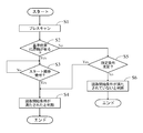
- the flowchart of FIG. 9 starts when the document cover 102 is closed (immediately before the document cover 102 is completely closed). That is, the flowchart of FIG. 9 starts when the control unit 4 detects that the document cover 102 is closed until the tilt angle of the document cover 102 reaches a predetermined angle.
- step S1 the control unit 4 causes the image reading unit 1 to perform a prescan.
- the image reading unit 1 reads a predetermined area A (see FIG. 3) including the reference position RP in the contact glass 10.
- the pre-scan reading is performed for a predetermined number of lines from the reading start line SL.
- the predetermined region A is indicated by a alternate long and short dash line.
- the reading for generating the first image data 11 is referred to as normal reading and is distinguished from pre-scan.
- step S2 the control unit 4 determines whether or not the document D is present in the reference position RP based on the image data obtained by the prescan. If the set state of the document D (card document CD) is as shown in FIG. 3, it is determined that the document D is in the reference position RP. Even if the document D is set on the set surface 10S, if the corners of the document D are not aligned with the reference position RP, it is determined that there is no document D in the reference position RP.
- control unit 4 determines that the document D is in the reference position RP, the start operation for requesting a transmission job (the operation of pressing the start button on the operation panel 3) is enabled. On the other hand, when the control unit 4 determines that the document D does not exist in the reference position RP, the start operation for requesting the transmission job is invalidated.
- step S3 the control unit 4 determines whether or not the operation panel 3 has accepted the start operation.
- step S4 determines that the start operation is not accepted, the process of step S4 is repeated.
- step S4 the control unit 4 determines that the reading start condition is satisfied. That is, when the user aligns the corner of the document D with the reference position RP, the transmission job (reading by the image reading unit 1) is started by the user performing a start operation on the operation panel 3.
- step S2 if the control unit 4 determines that there is no document D in the reference position RP, the process proceeds to step S5. That is, when the start operation for the operation panel 3 is invalidated, the process proceeds from step S2 to step S5. When the process proceeds to step S5, the control unit 4 determines whether or not the predetermined condition is satisfied.
- step S5 the process of step S5 will be specifically described.
- the control unit 4 starts measuring the time when the transmission job accompanied by the normal reading is completed. Then, when the control unit 4 determines whether or not the predetermined condition is satisfied, the elapsed time from the completion of the previous (most recent) transmission job reaches a predetermined time (for example, several tens of seconds to several minutes). Judge whether or not it is. As a result, when the elapsed time reaches the predetermined time, the control unit 4 determines that the predetermined condition is satisfied.
- a predetermined time for example, several tens of seconds to several minutes.
- the control unit 4 causes the operation panel 3 to accept a predetermined end operation as an operation for instructing the end of the transmission job.
- the operation panel 3 accepts an operation for a predetermined hardware button 32 as an end operation.
- the control unit 4 determines whether or not the operation panel 3 has accepted the end operation after the previous transmission job is completed. As a result, when the operation panel 3 accepts the end operation, the control unit 4 determines that the predetermined condition is satisfied.
- control unit 4 determines that the predetermined condition is satisfied if the elapsed time from the completion of the previous transmission job reaches the predetermined time. Further, the control unit 4 determines that the predetermined condition is satisfied if the operation panel 3 accepts the end operation even if the elapsed time from the completion of the previous transmission job has not reached the predetermined time.
- step S5 If the control unit 4 determines in step S5 that the predetermined condition is satisfied, the process proceeds to step S4. If the predetermined condition is satisfied, it is highly possible that the user opens and closes the document cover 102 in order to set the document D on the setting surface 10S. In other words, there is a high possibility that the document D is set on the set surface 10S. After the elapsed time from the completion of the previous transmission job reaches a predetermined time, or after the operation panel 3 accepts the end operation after the completion of the previous transmission job, for example, the user is in the state shown in FIG. When the document D (card document CD) is set on the set surface 10S and the document cover 102 is closed, it is determined that the predetermined conditions are satisfied.
- the predetermined condition it is satisfied, it is highly possible that the user opens and closes the document cover 102 in order to set the document D on the setting surface 10S. In other words, there is a high possibility that the document D is set on the set surface 10S. After the elapsed time from
- step S4 the control unit 4 determines that the reading start condition is satisfied. That is, even if the user does not align the corner of the document D with the reference position RP (even if the start operation for the operation panel 3 is disabled), the elapsed time from the completion of the previous transmission job has reached the predetermined time. If the operation panel 3 accepts the end operation after the completion of the previous transmission job, the transmission is automatically (forced) even if the user does not perform the start operation on the operation panel 3. The job is started. Even if the user presses the start button on the operation panel 3, the operation is not accepted as a start operation (the operation is invalid).
- step S5 determines in step S5 that the predetermined condition is not satisfied
- the process proceeds to step S6. If the predetermined condition is not satisfied, it is highly possible that the user opens and closes the document cover 102 in order to remove the document D from the set surface 10S after the transmission job is completed. In other words, there is a high possibility that the document D is not set on the set surface 10S. Therefore, when the process proceeds to step S6, the control unit 4 determines that the reading start condition is not satisfied. In this case, the transmission job (reading by the image reading unit 1) is not started.
- the start of the flowchart of FIG. 11 is when the control unit 4 determines that the reading start condition is satisfied.
- step S11 the control unit 4 sets the reading range by the image reading unit 1. Then, the control unit 4 causes the image reading unit 1 to read the set reading range. The image reading unit 1 reads the set reading range and generates the first image data 11 (image data in the reading area).
- step S12 the control unit 4 detects the size of the document D set on the set surface 10S.
- the control unit 4 recognizes the document area (the area where the image of the document D exists) in the first image data 11.
- the control unit 4 detects the contour line (edge image forming the contour line) of the document D by performing edge detection processing on the first image data 11.
- the control unit 4 recognizes the area surrounded by the contour line detected by the edge detection process as the document area.
- the control unit 4 detects the size of the document region (width in the main scanning direction and width in the sub-scanning direction) existing in the first image data 11 as the size of the document D set on the set surface 10S.
- the control unit 4 determines whether or not the detected size of the document D (hereinafter referred to as the detection size) is within a predetermined range.
- the predetermined range includes a range in the main scanning direction (hereinafter referred to as the first range) and a range in the sub-scanning direction (hereinafter referred to as the second range).
- the maximum value of the first range is 210 mm
- the minimum value of the first range is 50 mm.
- the maximum value of the second range is 210 mm
- the minimum value of the second range is 50 mm.
- the detection range is within the predetermined range.
- the control unit 4 deviates from the predetermined range if the width of the detection size in the sub-scanning direction is out of the second range.
- the control unit 4 deviates from the predetermined range if the width of the detection size in the main scanning direction is out of the first range.
- step S13 determines in step S13 that the detection size is within the predetermined range. If the detection size is within the predetermined range, it is highly possible that the ID card (card original CD) is set as the original D to be read.
- step S11 the image reading unit 1 performs a pre-scan. Therefore, when the document D is located at the reference position RP, the width of the document D set on the set surface 10S in the main scanning direction can be detected based on the image data obtained by the pre-scan. Therefore, as a modification when the document D is present at the reference position RP, the following configuration may be performed.
- the control unit 4 detects the width in the main scanning direction of the document D set on the set surface 10S based on the image data obtained by the pre-scan, and the detected width is the first range. Determine if it fits in. Then, when the control unit 4 determines that the width of the document D set on the set surface 10S in the main scanning direction is within the first range, the process proceeds to step S14.
- the control unit 4 performs a crop process for extracting the image data of the document D (the image data of the document area detected by the edge detection process) from the first image data 11. That is, the control unit 4 extracts the second image data 12 from the first image data 11.
- the control unit 4 performs a process of correcting the inclination of the image, the distortion of the image, and the like on the second image data 12 extracted by the crop process.
- step S15 the control unit 4 generates a first preview image 71 (see each of the lower figures of FIGS. 12 and 13) corresponding to the first image data 11. Further, the control unit 4 generates a second preview image (see each of the lower figures of FIGS. 12 and 13) corresponding to the second image data 12. In other words, the control unit 4 generates display data for each of the first image data 11 and the second image data 12.
- step S16 the control unit 4 causes the operation panel 3 to accept a selection operation for selecting which of the first image data 11 and the second image data 12 is to be output.
- the control unit 4 causes the operation panel 3 to display the selection screen 7 on which the first preview image 71 and the second preview image 72 are arranged, as shown in the lower figures of FIGS. 12 and 13.
- the operation panel 3 displays the selection screen 7 and accepts the selection operation from the user.
- the selection screen 7 as shown in the lower figure of FIG. 12 is displayed. Is displayed.
- the operation panel 3 accepts a touch operation (for example, a tap operation) on the display area of either the first preview image 71 or the second preview image 72 as a selection operation while the selection screen 7 is being displayed.
- a touch operation for example, a tap operation
- the control unit 4 determines that the first image data 11 is selected.
- the control unit 4 determines that the second image data 12 has been selected.
- step S17 the control unit 4 determines whether or not the first image data 11 has been selected.
- the process proceeds to step S18.
- the control unit 4 determines that the second image data 12 has been selected (the first image data 11 has not been selected)
- the process proceeds to step S19.
- step S18 the control unit 4 performs image processing on the first image data 11. Then, the control unit 4 causes the output unit 6 to output the first image data 11 after the image processing.
- step S19 the control unit 4 performs image processing on the second image data 12. Then, the control unit 4 causes the output unit 6 to output the second image data 12 after the image processing.
- step S18 If the control unit 4 determines in step S13 that the detection size is out of the predetermined range, the process proceeds to step S18.
- the fact that the detection size deviates from the predetermined size means that the document D set on the set surface 10S is not a card document CD. In other words, there is a high possibility that the standard size document D is set on the set surface 10S. In other words, there is a high possibility that the size indicated by the set value (set value set by the user) of the setting item "original size" and the size of the original D actually set on the set surface 10S match. .. Therefore, if the detection size is out of the predetermined range, the process proceeds to step S18.
- the setting value of the setting item "original size” is set to A4 size.
- the manuscript D actually set on the set surface 10S is the card manuscript CD.
- the setting position of the card document CD on the setting surface 10S is out of the range corresponding to the A4 size. This state is shown in FIG. In FIG. 14, the card original CD is indicated by a dot pattern, and the range corresponding to the A4 size is surrounded by a broken line.
- the image data (second image data 12) of the card manuscript CD will be interrupted. Therefore, when there is no document D in the reference position RP (when there is a possibility that the card document CD is set on the setting surface 10S), the entire surface of the contact glass 10 may be scanned as normal scanning.
- the compound machine 100 (image forming apparatus) of the present embodiment has an operation panel 3 for displaying an image and receiving an operation from a user, an output unit 6 for outputting image data to an external device 200, and a manuscript D. It is provided with an image reading unit 1 for normal reading that reads the contact glass 10 in which the is set and generates first image data 11 which is image data of the read region, and a control unit 4 for performing output data selection processing. When performing the output data selection process, the control unit 4 extracts the second image data 12, which is the image data of the original D, from the first image data 11.
- control unit 4 displays the first preview image 71 corresponding to the first image data 11 and the second preview image 72 corresponding to the second image data 12 on the operation panel 3, and displays the first preview image 71 and the second preview image 72.
- the operation panel 3 is made to accept the selection operation for selecting any of the preview images 72.
- the control unit 4 causes the output unit 6 to output the first image data 11.
- the control unit 4 causes the output unit 6 to output the second image data 12.
- the selection of whether to output the first image data 11 or the second image data 12 is accepted. Is done.
- the image data of the area desired by the user among the image data obtained by the normal reading.
- the user selects the second image data 12 only the image data of the original area is output from the image data of the reading area read by the image reading unit 1, and the image data of the area outside the original is not output. It is convenient for users who want to output only the image data of the original area.
- the user selects the first image data 11 the image data of the entire area of the reading area read by the image reading unit 1 is output, so that the user who wants to output the image data of the entire area of the reading area. The convenience of is not impaired.
- the first preview image 71 and the second preview image 72 are displayed, after confirming the output results of the first image data 11 and the second image data 12, the first image data 11 and the second image data D12 You can select the image data to be output. As a result, the convenience of the user is further improved.
- the control unit 4 detects the size of the document D set in the contact glass 10. Then, the control unit 4 causes the operation panel 3 to accept the selection operation when the size of the document D is within the predetermined range, and accepts the selection operation when the size of the document D is out of the predetermined range. Is not performed on the operation panel 3, but the output unit 6 is made to output the first image data 11. As a result, it is possible to prevent unnecessary selection and reception of image data to be output to the external device 200.
- the control unit 4 causes the image reading unit 1 to read (prescan) a predetermined area A including the reference position RP in the contact glass 10. Based on the image data obtained by reading the predetermined area A, it is determined whether or not the document D is present in the reference position RP. Then, when the document D is in the reference position RP, the control unit 4 causes the image reading unit 1 to perform normal reading after the operation panel 3 accepts the start operation. On the other hand, when there is no document D in the reference position RP, the control unit 4 causes the image reading unit 1 to perform normal reading even if the operation panel 3 does not accept the start operation.
- the corner of the document D may not be aligned with the reference position RP when the document D is set on the contact glass 10. Therefore, when the document cover 102 is closed, it is preferable that the document cover 102 is normally read even if the document D is not present at the reference position RP.
- the document cover 102 is also opened and closed when the user pulls out the document D from the contact glass 10. That is, the document cover 102 may be closed when the document D is not set on the contact glass 10.
- the control unit 4 detects that there is no document D in the reference position RP when the document cover 102 is closed until a predetermined condition is satisfied after the completion of normal scanning. Even so, the image reading unit 1 is not allowed to perform normal reading.
- the control unit 4 states that the predetermined condition is satisfied when the elapsed time from the completion of the normal reading reaches a predetermined time, or when the operation panel 3 accepts the end operation after the normal reading is completed. to decide.
Abstract
画像形成装置(100)は、第1画像データ(11)から原稿の画像データである第2画像データ(12)を抽出し、第1画像データ(11)に対応する第1プレビュー画像(71)および第2画像データ(12)に対応する第2プレビュー画像(72)のいずれかを選択する操作の受け付けを行い、第1プレビュー画像(71)が選択された場合、第1画像データ(11)の出力を行い、第2プレビュー画像(72)が選択された場合、第2画像データ(12)の出力を行う。
Description
本発明は、原稿の読み取りが可能な画像形成装置に関する。
原稿の読み取りが可能な画像形成装置は、画像読取部を備える。画像読取部は、ユーザーにより設定された範囲を読み取る(たとえば、特許文献1参照)。
画像形成装置には、コンタクトガラスにセットされた原稿を読み取るものがある。このような画像形成装置は、原稿がセットされたコンタクトガラスのうちユーザーにより設定された読取範囲を読み取る。
コンタクトガラスにセットされる原稿のサイズは様々である。定型サイズ(たとえば、A4サイズ)の原稿がコンタクトガラスにセットされる場合もあるし、免許証、保険証および名刺など不定型サイズの原稿(定型サイズよりも小さいサイズのカード原稿)がコンタクトガラスにセットされる場合もある。
ここで、読取対象の原稿がA4サイズよりも小さいサイズのカード原稿である場合において、ユーザーが読取範囲をA4サイズに設定したとする。この場合、ユーザーは、コンタクトガラスのうちA4サイズに対応する範囲内にカード原稿をセットする。
この例では、画像形成装置は、カード原稿がセットされたコンタクトガラスのうちA4サイズに対応する範囲を読取範囲に設定し、設定した読取範囲を読み取る。そして、画像形成装置は、読み取った領域(読取範囲に対応する領域)の画像データを出力する。
画像形成装置から出力される画像データには、原稿領域(コンタクトガラスのうちカード原稿が存在する領域)の画像データが含まれるが、原稿外領域(コンタクトガラスのうちカード原稿が存在しない領域)の画像データも含まれる。したがって、カード原稿の画像データだけを出力したいユーザーにとっては利便性が悪い。
本発明は、上記課題を解決するためになされたものであり、読み取りで得られた画像データのうちユーザー所望の領域の画像データを出力することが可能な画像形成装置を提供することを目的とする。
上記目的を達成するために、本発明の画像形成装置は、画像を表示し、ユーザーから操作を受け付ける操作パネルと、外部機器にデータを出力する出力部と、原稿がセットされたコンタクトガラスを読み取り、読み取った領域の画像データである第1画像データを生成する通常読取を行う画像読取部と、出力データ選択処理を行う制御部と、を備える。出力データ選択処理を行うとき、制御部は、第1画像データから原稿の画像データである第2画像データを抽出する。また、制御部は、第1画像データに対応する第1プレビュー画像および第2画像データに対応する第2プレビュー画像を操作パネルに表示させるとともに、第1プレビュー画像および第2プレビュー画像のいずれかを選択する選択操作の受け付けを操作パネルに行わせる。第1プレビュー画像が選択された場合、制御部は、第1画像データの出力を出力部に行わせる。第2プレビュー画像が選択された場合、制御部は、第2画像データの出力を出力部に行わせる。
本発明の構成では、読み取りで得られた画像データのうちユーザー所望の領域の画像データを出力することが可能な画像形成装置を提供することができる。
<複合機の構成>
図1に示すように、本実施形態の複合機100は、画像読取部1および印刷部2を備える。複合機100は「画像形成装置」に相当する。
図1に示すように、本実施形態の複合機100は、画像読取部1および印刷部2を備える。複合機100は「画像形成装置」に相当する。
画像読取部1は、図2に示すように、コンタクトガラス10を備える。コンタクトガラス10は、画像読取部1の筐体101の上部に設置される。コンタクトガラス10の上面は、原稿Dがセットされるセット面10Sとなる。画像読取部1は、コンタクトガラス10を読み取り、読み取った領域の画像データを生成する。セット面10Sに原稿Dがセットされている場合には、セット面10Sにセットされた原稿Dの読み取りが行われる。
セット面10Sは、図3に示すように、平面視において複合機100の左右方向に長い矩形状である。セット面10Sの4辺のうち、一対の短辺が主走査方向(複合機100の前後方向)に対して平行となり、一対の長辺が副走査方向(主走査方向と直交する方向)に対して平行となる。
ここで、セット面10Sの副走査方向に対向する一対の辺(主走査方向に平行な一対の辺)のうち一方辺が第1基準辺RS1に設定され、セット面10Sの主走査方向に対向する一対の辺(副走査方向に平行な一対の辺)のうち一方辺が第2基準辺RS2に設定される。また、第1基準辺RS1と第2基準辺RS2との交点が基準位置RPに設定される。図3では、セット面10Sの左上角の位置が基準位置RPに設定された例を図示する。
画像読取部1は、読取開始ラインSLから読み取りを開始する。ここで、読取開始ラインSLは、第1基準辺RS1に沿ったラインである。このため、セット面10Sに原稿Dをセットするとき、ユーザーは原稿Dの或る角を基準位置RPに合わせる。また、原稿Dの4辺のうち、或る辺を第1基準辺RS1に合わせるとともに、他の辺を第2基準辺RS2に合わせる。
また、図4に示すように、筐体101には、原稿カバー102が設置される。原稿カバー102は、セット面10Sに対して開閉する。たとえば、筐体101の後方部分に回転軸103が設けられる。原稿カバー102は、回転軸103に回動可能に支持される。原稿カバー102は、前方部分を自由端とし、前方部分を上下方向に振るように回動する。これにより、原稿カバー102の前方部分を上下方向に持ち上げたり持ち下げたりすることにより、セット面10Sに対して原稿カバー102を開閉させることができる。
原稿カバー102が開けられると、セット面10Sが露出し、セット面10Sへの原稿Dのセットが可能な状態となる(図4上図参照)。原稿カバー102が閉じられると、原稿カバー102によってセット面10Sが覆われた状態となる(図4下図参照)。セット面10Sに原稿Dをセットするとき、ユーザーは原稿カバー102を開ける。セット面102に原稿Dをセットした後、ユーザーは原稿カバー102を閉じる。原稿カバー102が閉じられることにより、セット面10S上の原稿Dが原稿カバー102で押え付けられる。
また、図2に示すように、画像読取部1は、光源11、イメージセンサー12、ミラー13およびレンズ14を備える。これら画像読取部1の各部材は、筐体101の内部に収容される。
光源11は、複数のLED素子(図示せず)を有する。複数のLED素子は、主走査方向(図2の紙面に対して垂直な方向)に配列される。光源11は、コンタクトガラス10に向けて光を照射する。光源11からの光はコンタクトガラス10を透過する。原稿Dがセットされている領域では、光源11からの光が原稿Dで反射される。
イメージセンサー12は、主走査方向に並ぶ複数の光電変換素子を有する。イメージセンサー12は、原稿Dで反射された光を受光する。イメージセンサー12は、光を受光すると、ライン単位で画素毎に光電変換して電荷を蓄積するとともに、蓄積電荷に応じた信号を出力する。
ミラー13は、原稿Dで反射された光をレンズ14に向けて反射する。レンズ14は、ミラー13で反射された光を集光し、イメージセンサー12に導く。
光源11およびミラー13は、副走査方向に移動可能なキャリッジ15に設置される。キャリッジ15は、ワイヤー16に連結される。ワイヤー16は、巻取ドラム17に巻回される。巻取ドラム17が回転すると、キャリッジ15が副走査方向に移動する。すなわち、光源11およびミラー13が副走査方向に移動する。
画像読取部1による読み取りを伴うジョブ(コピージョブおよび送信ジョブなど)の実行時、キャリッジ15が副走査方向(正面から見て左から右に向かう方向)に移動する。キャリッジ15が副走査方向に移動しているとき、光源11がコンタクトガラス10に向けて光を照射する。また、原稿Dで反射された反射光の光電変換をイメージセンサー12が繰り返し行う。これにより、原稿Dの読み取りがライン単位で行われる。
また、図1に示すように、印刷部2は、用紙搬送路20を備える。図1では、用紙搬送路20を破線で示す。印刷部2は、用紙搬送路20に沿って搬送されている用紙Pに画像を印刷する。コピージョブでは、画像読取部1による読み取りで得られた画像データに基づく画像の用紙Pへの印刷が印刷部2により行われる。印刷部2は、給紙部21、画像形成部22および定着部23を備える。
給紙部21は、用紙搬送路20に用紙Pを給紙する。画像形成部22は、トナー像(画像)を形成し、搬送中の用紙Pにトナー像を転写(印刷)する。定着部23は、搬送中の用紙Pを加熱および加圧する。これにより、用紙Pにトナー像が定着される。
また、複合機100は、操作パネル3を備える。操作パネル3には、タッチスクリーン31が設けられる。タッチスクリーン31は、ソフトウェアボタンを含む画面を表示し、表示画面(ソフトウェアボタン)に対するタッチ操作をユーザーから受け付ける。
操作パネル3には、ハードウェアボタン32も設けられる。ハードウェアボタン32の設置数は複数である。ハードウェアボタン32としては、画像読取部1による読み取りを伴うジョブを要求するスタート操作をユーザーから受け付けるためのスタートボタンなどがある。
また、図5に示すように、複合機100は、制御部4および記憶部5を備える。制御部4は、CPUを含む。記憶部5は、ROMおよびRAMを含む。記憶部5は、制御部4に接続される。記憶部5は、制御プログラムおよび制御データを記憶する。制御部4は、制御プログラムおよび制御データに基づき、複合機100の各部を制御する。
画像読取部1、印刷部2および操作パネル3は、制御部4に接続される。制御部4は、画像読取部1の読取動作を制御するとともに、印刷部2の印刷動作を制御する。また、制御部4は、操作パネル3の表示動作を制御するとともに、操作パネル3に対して行われた操作を検知する。
制御部4には、カバーセンサーCSが接続される。カバーセンサーCSは、原稿カバー102の開閉を検知するためのセンサーである。たとえば、カバーセンサーCSとして、発光部および受光部を有する光センサーが用いられる。カバーセンサーCSは、発光部と受光部との間を上下方向に移動可能なアクチュエーター(図示せず)を検知対象とする。アクチュエーターは、筐体101に設けられる。アクチュエーターは、上方に向けて常に付勢される。
原稿カバー102が完全に閉じられているときには(図4下図参照)、原稿カバー102によってアクチュエーターが下方に押圧された状態となっている。このときには、カバーセンサーCSの光路(発光部と受光部との間の領域)がアクチュエーターによって遮蔽されている。一方で、原稿カバー102が完全に開けられているときには(図4上図参照)、原稿カバー102によるアクチュエーターに対する押圧が解除された状態となっている。このときには、カバーセンサーCSの光路は開放されている。
原稿カバー101が開けられた状態から閉じられた状態に遷移するとき、原稿カバー102がアクチュエーターに当接し、アクチュエーターが下方に移動する。そして、原稿カバー102の傾斜角度(セット面10Sとの間の角度)が所定角度になるまで原稿カバー102が閉じられたとき、カバーセンサーCSの光路がアクチュエーターによって遮蔽される。このとき、カバーセンサーCSの出力値が変化する。
制御部4は、カバーセンサーCSの出力値を監視する。制御部4は、カバーセンサーCSの出力値に基づき、原稿カバーCSの開閉を検知する。また、制御部4は、カバーセンサーCSの出力値に基づき、開けられていた原稿カバー102の傾斜角度が所定角度になったことを検知する。
ここで、画像読取部1による読み取りを伴うジョブ(コピージョブおよび送信ジョブなど)の開始前、ユーザーは、原稿カバー102を開けてセット面10Sに原稿をセットする。その後、ユーザーは、原稿カバー102を閉じる。
また、画像読取部1による読み取りを伴うジョブの完了後、ユーザーは、原稿カバー102を開けてセット面10Sから原稿Dを抜き取る。その後、ユーザーは、原稿カバー102を閉じる。
このように、原稿カバー102の開閉は、ジョブの開始前およびジョブの完了後に行われる。すなわち、開けられていた原稿カバー102の傾斜角度が所定角度になったことを制御部4が検知するのは、ジョブの開始前およびジョブの完了後である。
また、複合機100には、ネットワーク通信部61が設けられる。ネットワーク通信部61は、インターネットなどのネットワークNTに複合機100を接続するためのインターフェースである。ネットワーク通信部61は、LAN通信回路を含む。ネットワーク通信部61は、無線LANアクセスポイントに接続される。
制御部4は、ネットワーク通信部61を制御し、ネットワークNTに接続された外部機器と通信する。ネットワークNTに接続される外部機器としては、複合機100のユーザーにより使用されるPC201(パーソナルコンピューター)がある。複合機100にPC201を接続することにより、複合機100からPC201に対して画像データを送信する送信ジョブの実行が可能となる。たとえば、画像読取部1による読み取りで得られた画像データをPC201に送信することができる。
また、複合機100には、USBインターフェース部62が設けられる。USBインターフェース部62は、複合機100に外部機器をUSB接続するためのインターフェースである。USBメモリーなどのUSBデバイス202を複合機100に接続することができる。USBインターフェース部62は、USB通信回路を含む。
制御部4は、USBインターフェース部62を制御し、複合機100に接続されたUSBデバイス202と通信する。制御部4は、USBデバイス202への情報の書き込みを行うとともに、USBデバイス202からの情報の読み出しを行う。複合機100にUSBデバイス202を接続することにより、複合機100からUSBデバイス202に対して画像データを送信する送信ジョブの実行が可能となる。たとえば、画像読取部1による読み取りで得られた画像データをUSBデバイス202に送信することができる。
なお、ネットワーク通信部61およびUSBインターフェース部62は「出力部」に相当する。以下の説明では、ネットワーク通信部61およびUSBインターフェース部62を総じて出力部6と称する。また、PC201およびUSBデバイス202を総じて外部機器200と称する。制御部4は、外部機器200への画像データの出力を出力部6に行わせる。
<送信ジョブ>
送信ジョブでは、画像読取部1による読み取りで得られた画像データが複合機100から外部機器200に送信される。外部機器200は、複合機100から受信した画像データを保存する。
送信ジョブでは、画像読取部1による読み取りで得られた画像データが複合機100から外部機器200に送信される。外部機器200は、複合機100から受信した画像データを保存する。
送信ジョブの開始前、ユーザーは、送信ジョブに関する設定(画像読取部1による読み取りに関する設定)を行う。送信ジョブに関する設定の受け付けは操作パネル3が行う。送信ジョブに関する設定項目は複数存在する。当該複数存在する設定項目の中には、「原稿サイズ(読取範囲)」という設定項目、「送信サイズ」という設定項目、および、「ズーム」という設定項目がある。
制御部4は、設定項目「原稿サイズ」の設定値に基づき、画像読取部1による読取範囲を設定する。また、制御部4は、設定項目「送信サイズ」の設定値および設定項目「ズーム」の設定値に基づき、画像読取部1による読み取りで得られた画像データに対して画像処理を行う。
ここで、図3に示すように、送信ジョブの実行に際し、不定型サイズ(定型サイズよりも小さいサイズ)のカード原稿CDが読取対象の原稿Dとしてセット面10Sにセットされたとする。カード原稿CDは、たとえば、免許証、保険証および名刺などのIDカードである。なお、図3では、カード原稿CDをドット柄で示す。また、定型サイズの1つであるA4サイズに対応する範囲を破線で囲む。
そして、第1の例として、設定項目「原稿サイズ」の設定値がA4サイズに設定され、設定項目「送信サイズ」の設定値がA4サイズ(原稿サイズと同じサイズ)に設定され、設定項目「ズーム」の設定値が100%に設定されたとする。
この場合、制御部4は、設定項目「原稿サイズ」の設定値であるA4サイズに対応する範囲(図3の破線で囲まれた範囲)を画像読取部1の読取範囲として設定する。また、制御部4は、設定読取範囲(設定項目「原稿サイズ」の設定値に基づき設定した読取範囲)の読み取りを画像読取部1に行わせる。画像読取部1は、設定読取範囲を読み取り、読取領域(設定読取範囲に対応する領域)の画像データを生成する。ここで、設定読取範囲はA4サイズに対応する範囲であるので、読取領域の画像データにはカード原稿CDの画像データが含まれる。
なお、読取領域の画像データは「第1画像データ」に相当し、カード原稿CDの画像データは「第2画像データ」に相当する。以下の説明では、読取領域の画像データを第1画像データと称し符号11を付す。カード原稿CDの画像データを第2画像データと称し符号12を付す。
第1の例では、図6上図に示すような画像データが第1画像データ11として生成される。第1画像データ11には第2画像データ12が含まれる。図6では、第2画像データ12をドット柄で示す。以降の説明で参照する図面についても同様とする。
第1画像データ11の生成後、制御部4は、第1画像データ11に対して、種々の画像処理を行う。たとえば、濃度変換処理およびデータ形式変換処理などが画像処理として行われる。また、制御部4は、第1画像データ11のサイズ(主走査方向の幅および副走査方向の幅)を設定項目「送信サイズ」の設定値で示されるサイズに合わせる処理を行う。
第1の例では、設定項目「送信サイズ」の設定値がA4サイズであり、設定項目「ズーム」の設定値が100%である。このため、第1画像データ11のサイズはA4サイズに設定される。また、第1画像データ11の拡大縮小は行われない。画像処理後の第1画像データ11を図6下図に示す。
第1画像データ11に対する画像処理後、制御部4は、画像処理後の第1画像データ11の出力を出力部6に行わせる。第1の例では、図6下図に示す第1画像データ11が出力される。
出力先の設定は操作パネル3がユーザーから受け付ける。出力先がPC201である場合、制御部4は、ネットワーク通信部61を制御し、PC201に対して画像処理後の第1画像データ11を送信する。出力先がUSBデバイス202である場合、制御部4は、USBインターフェース部62を制御し、USBデバイス202に対して画像処理後の第1画像データ11を送信する。
また、第2の例として、設定項目「原稿サイズ」の設定値がA4サイズに設定され、設定項目「送信サイズ」の設定値がA5サイズに設定され、設定項目「ズーム」の設定値が自動に設定されたとする。
この場合には、第1の例と同様、画像読取部1の読取範囲がA4サイズに対応する範囲に設定される。そして、設定読取範囲の読み取りが画像読取部1により行われる。これにより、図7上図に示すように、第2画像データ12を含む第1画像データ11(第1の例と同じ第1画像データ11)が生成される。
また、第1画像データ11の生成後、制御部4は、第1画像データ11に対して画像処理を行う。制御部4は、第1画像データ11に対して画像処理を行うことにより、第1画像データ11のサイズを設定項目「送信サイズ」の設定値で示されるサイズに合わせる。
第2の例では、設定項目「送信サイズ」の設定値がA5サイズであり、設定項目「ズーム」の設定値が自動である。このため、第1画像データ11のサイズはA5サイズに設定される。また、設定項目「ズーム」の設定値が自動であるので、第1画像データ11はA5サイズに縮小される。画像処理後(縮小後)の第1画像データ11を図7下図に示す。
第1画像データ11に対する画像処理後、制御部4は、画像処理後の第1画像データ11の出力を出力部6に行わせる。第2の例では、図7下図に示す第1画像データ11が出力される。
また、第3の例として、設定項目「原稿サイズ」の設定値がA4サイズに設定され、設定項目「送信サイズ」の設定値がA5サイズに設定され、設定項目「ズーム」の設定値が100%に設定されたとする。
この場合には、第1および第2の例と同様、A4サイズに対応する範囲が読取範囲として設定される。そして、設定読取範囲の読み取りが行われる。これにより、図8上図に示すように、第2画像データ12を含む第1画像データ11(第1および第2の例と同じ第1画像データ11)が生成される。
また、第1画像データ11の生成後、制御部4は、第1画像データ11に対して画像処理を行う。制御部4は、第1画像データ11に対して画像処理を行うことにより、第1画像データ11のサイズを設定項目「送信サイズ」の設定値で示されるサイズに合わせる。
第3の例では、設定項目「送信サイズ」の設定値がA5サイズであり、設定項目「ズーム」の設定値が100%である。このため、第1画像データ11のサイズはA5サイズに設定される。また、設定項目「ズーム」の設定値が100%であるので、第1画像データ11は縮小されない。この場合には、第1画像データ11に対するトリミング処理が行われる。画像処理後(トリミング後)の第1画像データ11を図8下図に示す。図8下図では、第1画像データ11のトリミングされた領域をハッチングで示す。
第1画像データ11に対する画像処理後、制御部4は、画像処理後の第1画像データ11の出力を出力部6に行わせる。第3の例では、図8下図に示す第1画像データ11が出力される。
<出力データ選択処理>
第1~第3の例では、第1画像データ11が出力される。言い換えると、第2画像データ12以外の画像データが第2画像データ12と共に出力される。第2画像データ12以外の画像データにはカード原稿CDの画像が存在しない。したがって、第2画像データ12以外の画像データは不要である。しかし、ユーザーによっては、第1画像データ11を出力したい場合がある。
第1~第3の例では、第1画像データ11が出力される。言い換えると、第2画像データ12以外の画像データが第2画像データ12と共に出力される。第2画像データ12以外の画像データにはカード原稿CDの画像が存在しない。したがって、第2画像データ12以外の画像データは不要である。しかし、ユーザーによっては、第1画像データ11を出力したい場合がある。
そこで、本実施形態では、第1画像データ11および第2画像データ12のうちユーザーにより選択された画像データを出力する出力データ選択機能が複合機100に搭載される。出力データ選択機能に関する処理(以下、出力データ選択処理と称する)は制御部4が行う。制御部4は、出力データ選択処理に先立って、読取開始条件が満たされたか否かを判断する条件判断処理を行う。
制御部4は、出力データ選択機能が有効に設定されている場合に出力データ選択処理を行う。出力データ選択機能の有効無効の設定は操作パネル3がユーザーから受け付ける。出力データ選択機能を有効に設定することにより、図6~図8の各下図に示したような画像データが出力されるのを抑制することができる。
まず、図9に示すフローチャートを参照し、制御部4が行う条件判断処理の流れについて説明する。図9のフローチャートのスタート時点では、ユーザーが送信ジョブに関する設定を完了させているとする。送信ジョブに関する設定が完了すると、ユーザーはセット面10Sに原稿Dをセットし、原稿カバー102を閉じる。したがって、図9のフローチャートのスタート時点では、セット面10Sに原稿Dが既にセットされている。
ここで、図9のフローチャートのスタート時点では、定型サイズの原稿Dがセット面10Sにセットされている場合もあれば、不定型サイズの原稿D(カード原稿CD)がセット面10Sにセットされている場合もある。また、原稿Dの角が基準位置RPに合わされている場合もあれば、原稿Dの角が基準位置RPに合わされていない場合もある。
図9のフローチャートのスタートは、原稿カバー102が閉じられるとき(原稿カバー102が完全に閉じられた状態になる直前)である。すなわち、図9のフローチャートのスタートは、原稿カバー102の傾斜角度が所定角度になるまで原稿カバー102が閉じられたことを制御部4が検知したときである。
ステップS1において、制御部4は、画像読取部1にプレスキャンを行わせる。画像読取部1は、プレスキャンとして、コンタクトガラス10のうち基準位置RPを含む所定領域A(図3参照)の読み取りを行う。プレスキャンでは、読取開始ラインSLから所定ライン数分の読み取りが行われる。図3では、所定領域Aを一点鎖線で示す。以下の説明では、第1画像データ11を生成するための読み取り(設定読取範囲の読み取り)を通常読取と称し、プレスキャンと区別する。
ステップS2において、制御部4は、プレスキャンで得られた画像データに基づき、基準位置RPに原稿Dが有るか否かを判断する。原稿D(カード原稿CD)のセット状態が図3に示す状態であれば、基準位置RPに原稿Dが有ると判断される。セット面10Sに原稿Dがセットされていても、原稿Dの角が基準位置RPに合わされていなければ、基準位置RPに原稿Dが無いと判断される。
なお、基準位置RPに原稿Dが有ると制御部4が判断した場合、送信ジョブを要求するスタート操作(操作パネル3のスタートボタンを押す操作)が有効化される。一方で、基準位置RPに原稿Dが無いと制御部4が判断した場合には、送信ジョブを要求するスタート操作が無効化される。
ステップS2において、基準位置RPに原稿Dが有ると制御部4が判断した場合には、ステップS3に移行する。すなわち、操作パネル3に対するスタート操作が有効化されている場合には、ステップS2からステップS3に移行する。ステップS3に移行すると、制御部4は、操作パネル3がスタート操作を受け付けたか否かを判断する。スタート操作を受け付けたと制御部4が判断した場合には、ステップS4に移行する。スタート操作を受け付けていないと制御部4が判断した場合には、ステップS4の処理が繰り返される。
ステップS4に移行すると、制御部4は、読取開始条件が満たされたと判断する。すなわち、ユーザーが原稿Dの角を基準位置RPに合わせた場合には、ユーザーが操作パネル3に対してスタート操作を行うことにより、送信ジョブ(画像読取部1による読み取り)が開始される。
ステップS2において、基準位置RPに原稿Dが無いと制御部4が判断した場合には、ステップS5に移行する。すなわち、操作パネル3に対するスタート操作が無効化されている場合には、ステップS2からステップS5に移行する。ステップS5に移行すると、制御部4は、所定条件が満たされているか否かを判断する。
ここで、ステップS5の処理について具体的に説明する。制御部4は、通常読取を伴う送信ジョブが完了すると、時間の計測を開始する。そして、制御部4は、所定条件が満たされたか否かを判断するとき、前回(直近)の送信ジョブが完了してからの経過時間が所定時間(たとえば、数十秒から数分)に達しているか否かを判断する。その結果、経過時間が所定時間に達している場合、制御部4は、所定条件が満たされていると判断する。
また、制御部4は、通常読取を伴う送信ジョブが完了すると、送信ジョブの終了を指示する操作として予め定められた終了操作の受け付けを操作パネル3に行わせる。操作パネル3は、所定のハードウェアボタン32に対する操作を終了操作として受け付ける。そして、制御部4は、所定条件が満たされたか否かを判断するとき、前回の送信ジョブが完了して以降に操作パネル3が終了操作を受け付けたか否かを判断する。その結果、操作パネル3が終了操作を受け付けている場合、制御部4は、所定条件が満たされていると判断する。
なお、制御部4は、操作パネル3が終了操作を受け付けていなくても、前回の送信ジョブの完了からの経過時間が所定時間に達していれば、所定条件が満たされていると判断する。また、制御部4は、前回の送信ジョブの完了からの経過時間が所定時間に達していなくても、操作パネル3が終了操作を受け付けていれば、所定条件が満たされていると判断する。
ステップS5において、所定条件が満たされていると制御部4が判断した場合には、ステップS4に移行する。所定条件が満たされているということは、ユーザーがセット面10Sに原稿Dをセットするために原稿カバー102を開閉した可能性が高い。言い換えると、セット面10Sに原稿Dがセットされている可能性が高い。前回の送信ジョブの完了からの経過時間が所定時間に達して以降、あるいは、前回の送信ジョブの完了後に操作パネル3が終了操作を受け付けて以降、たとえば、図10に示す状態となるようユーザーがセット面10Sに原稿D(カード原稿CD)をセットして原稿カバー102を閉じた場合には、所定条件が満たされていると判断される。
ステップS5からステップS4に移行すると、制御部4は、読取開始条件が満たされたと判断する。すなわち、ユーザーが原稿Dの角を基準位置RPに合わせていなくても(操作パネル3に対するスタート操作が無効化されていても)、前回の送信ジョブの完了からの経過時間が所定時間に達していた場合または前回の送信ジョブの完了後に操作パネル3が終了操作を受け付けていた場合には、ユーザーが操作パネル3に対してスタート操作を行っていなくても、自動的(強制的)に、送信ジョブが開始される。なお、仮に、ユーザーが操作パネル3のスタートボタンを押す操作を行っても、当該操作はスタート操作として受け付けられない(当該操作は無効となる)。
ステップS5において、所定条件が満たされていないと制御部4が判断した場合には、ステップS6に移行する。所定条件が満たされていないということは、送信ジョブの完了後、セット面10Sから原稿Dを抜き取るためにユーザーが原稿カバー102を開閉した可能性が高い。言い換えると、セット面10Sに原稿Dがセットされていない可能性が高い。したがって、ステップS6に移行すると、制御部4は、読取開始条件が満たされていないと判断する。この場合には、送信ジョブ(画像読取部1による読み取り)は開始されない。
次に、図11に示すフローチャートを参照し、制御部4が行う出力データ選択処理の流れについて説明する。図11のフローチャートのスタートは、読取開始条件が満たされたと制御部4が判断したときである。
ステップS11において、制御部4は、画像読取部1による読取範囲を設定する。そして、制御部4は、設定読取範囲の読み取りを画像読取部1に行わせる。画像読取部1は、設定読取範囲を読み取り、第1画像データ11(読取領域の画像データ)を生成する。
ステップS12において、制御部4は、セット面10Sにセットされている原稿Dのサイズを検知する。このとき、制御部4は、第1画像データ11内における原稿領域(原稿Dの画像が存在する領域)を認識する。たとえば、制御部4は、第1画像データ11に対してエッジ検出処理を行うことによって原稿Dの輪郭線(輪郭線を成すエッジ画像)を検出する。制御部4は、エッジ検出処理で検出した輪郭線で囲まれた領域を原稿領域として認識する。そして、制御部4は、第1画像データ11内に存在する原稿領域のサイズ(主走査方向の幅および副走査方向の幅)をセット面10Sにセットされている原稿Dのサイズとして検知する。
ステップS13において、制御部4は、検知した原稿Dのサイズ(以下、検知サイズと称する)が所定範囲に収まっているか否かを判断する。なお、所定範囲には、主走査方向の範囲(以下、第1範囲と称する)と副走査方向の範囲(以下、第2範囲と称する)とがある。たとえば、第1範囲の最大値は210mmであり、第1範囲の最小値は50mmである。第2範囲の最大値は210mmであり、第2範囲の最小値は50mmである。
制御部4は、検知サイズの主走査方向の幅が第1範囲に収まっており、かつ、検知サイズの副走査方向の幅が第2範囲に収まっていれば、検知範囲が所定範囲に収まっていると判断する。すなわち、制御部4は、検知サイズの主走査方向の幅が第1範囲に収まっていても、検知サイズの副走査方向の幅が第2範囲から外れていれば、検知範囲が所定範囲から外れていると判断する。また、制御部4は、検知サイズの副走査方向の幅が第2範囲に収まっていても、検知サイズの主走査方向の幅が第1範囲から外れていれば、検知範囲が所定範囲から外れていると判断する。
ステップS13において、検知サイズが所定範囲に収まっていると制御部4が判断した場合には、ステップS14に移行する。検知サイズが所定範囲に収まっているということは、読取対象の原稿DとしてIDカード(カード原稿CD)がセットされている可能性が高い。
なお、ステップS11において、画像読取部1は、プレスキャンを行う。したがって、基準位置RPに原稿Dが有る場合には、プレスキャンで得られた画像データに基づき、セット面10Sにセットされている原稿Dの主走査方向の幅を検知することができる。そこで、基準位置RPに原稿Dが有る場合の変形例として、以下のように構成してもよい。
変形例の構成では、制御部4は、プレスキャンで得られた画像データに基づき、セット面10Sにセットされている原稿Dの主走査方向の幅を検知し、当該検知した幅が第1範囲に収まっているか否かを判断する。そして、セット面10Sにセットされている原稿Dの主走査方向の幅が第1範囲に収まっていると制御部4が判断した場合にステップS14に移行する。
ステップS14に移行すると、制御部4は、第1画像データ11から原稿Dの画像データ(エッジ検出処理で検出した原稿領域の画像データ)を抽出するクロップ処理を行う。すなわち、制御部4は、第1画像データ11から第2画像データ12を抽出する。なお、制御部4は、クロップ処理で抽出した第2画像データ12に対して、画像の傾きおよび画像の歪などを補正する処理を行う。
その後、ステップS15において、制御部4は、第1画像データ11に対応する第1プレビュー画像71(図12および図13の各下図参照)を生成する。また、制御部4は、第2画像データ12に対応する第2プレビュー画像(図12および図13の各下図参照)を生成する。言い換えると、制御部4は、第1画像データ11および第2画像データ12のそれぞれの表示データを生成する。
ステップS16において、制御部4は、第1画像データ11および第2画像データ12のいずれを出力するかを選択する選択操作の受け付けを操作パネル3に行わせる。このとき、制御部4は、図12および図13の各下図に示すように、第1プレビュー画像71および第2プレビュー画像72を配した選択画面7を操作パネル3に表示させる。操作パネル3は、選択画面7を表示し、選択操作をユーザーから受け付ける。
なお、読取対象の原稿Dとしてカード原稿CDがセットされ、カード原稿CDの角が基準位置RPに合わされていた場合(図12上図参照)には、図12下図に示すような選択画面7が表示される。また、読取対象の原稿Dとしてカード原稿CDがセットされ、カード原稿CDの角が基準位置RPに合わされていなかった場合(図13上図参照)には、図13下図に示すような選択画面7が表示される。
操作パネル3は、選択画面7の表示中、第1プレビュー画像71および第2プレビュー画像72のいずれかの表示領域に対するタッチ操作(たとえば、タップ操作)を選択操作として受け付ける。第1プレビュー画像71に対する選択操作を検知した場合、制御部4は、第1画像データ11が選択されと判断する。第2プレビュー画像72に対する選択操作を検知した場合、制御部4は、第2画像データ12が選択されたと判断する。
図11に戻り、ステップS17において、制御部4は、第1画像データ11が選択されたか否かを判断する。第1画像データ11が選択されたと制御部4が判断した場合には、ステップS18に移行する。第2画像データ12が選択された(第1画像データ11が選択されなかった)と制御部4が判断した場合には、ステップS19に移行する。
ステップS18に移行した場合、制御部4は、第1画像データ11に対して画像処理を行う。そして、制御部4は、画像処理後の第1画像データ11の出力を出力部6に行わせる。一方で、ステップS19に移行した場合、制御部4は、第2画像データ12に対して画像処理を行う。そして、制御部4は、画像処理後の第2画像データ12の出力を出力部6に行わせる。
ステップS13において、検知サイズが所定範囲から外れていると制御部4が判断した場合には、ステップS18に移行する。検知サイズが所定サイズから外れているということは、セット面10Sにセットされている原稿Dがカード原稿CDではないということである。言い換えると、定型サイズの原稿Dがセット面10Sにセットされている可能性が高い。さらに言い換えると、設定項目「原稿サイズ」の設定値(ユーザーが設定した設定値)で示されるサイズとセット面10Sに実際にセットされている原稿Dのサイズとが一致している可能性が高い。そこで、検知サイズが所定範囲から外れている場合にはステップS18に移行する。
ここで、たとえば、設定項目「原稿サイズ」の設定値がA4サイズに設定されているとする。また、セット面10Sに実際にセットされている原稿Dがカード原稿CDであるとする。さらに、セット面10S上におけるカード原稿CDのセット位置がA4サイズに対応する範囲から外れているとする。この状態を図14に示す。図14では、カード原稿CDをドット柄で示し、A4サイズに対応する範囲を破線で囲む。
この例において、設定読取範囲(A4サイズに対応する範囲)だけの読み取りが行われると、カード原稿CDの画像データ(第2画像データ12)が途切れた状態となる。したがって、基準位置RPに原稿Dが無い場合(セット面10Sにカード原稿CDがセットされている可能性がある場合)には、通常読取としてコンタクトガラス10の全面の読み取りが行われてもよい。
本実施形態の複合機100(画像形成装置)は、上記のように、画像を表示し、ユーザーから操作を受け付ける操作パネル3と、外部機器200に画像データを出力する出力部6と、原稿Dがセットされたコンタクトガラス10を読み取り、読み取った領域の画像データである第1画像データ11を生成する通常読取を行う画像読取部1と、出力データ選択処理を行う制御部4と、を備える。出力データ選択処理を行うとき、制御部4は、第1画像データ11から原稿Dの画像データである第2画像データ12を抽出する。また、制御部4は、第1画像データ11に対応する第1プレビュー画像71および第2画像データ12に対応する第2プレビュー画像72を操作パネル3に表示させるとともに、第1プレビュー画像71および第2プレビュー画像72のいずれかを選択する選択操作の受け付けを操作パネル3に行わせる。第1プレビュー画像71が選択された場合、制御部4は、第1画像データ11の出力を出力部6に行わせる。第2プレビュー画像72が選択された場合、制御部4は、第2画像データ12の出力を出力部6に行わせる。
本実施形態の構成では、画像読取部1による通常読取の終了後、外部機器200への画像データの出力前に、第1画像データ11および第2画像データ12のいずれを出力するかの選択受付が行われる。これにより、通常読取で得られた画像データのうちユーザー所望の領域の画像データを出力することができる。ユーザーが第2画像データ12を選択した場合には、画像読取部1が読み取った読取領域の画像データのうち、原稿領域の画像データだけが出力され、原稿外領域の画像データは出力されないので、原稿領域の画像データだけを出力したいユーザーにとっては利便性が良い。一方で、ユーザーが第1画像データ11を選択した場合には、画像読取部1が読み取った読取領域の全領域の画像データが出力されるので、読取領域の全領域の画像データを出力したいユーザーの利便性が損なわれることはない。
さらに、第1プレビュー画像71および第2プレビュー画像72が表示されるので、第1画像データ11および第2画像データ12の出力結果を確認してから、第1画像データ11および第2画像データD12のうち出力する画像データを選択することができる。これにより、ユーザーの利便性がより向上する。
また、本実施形態では、上記のように、制御部4は、コンタクトガラス10にセットされている原稿Dのサイズを検知する。そして、制御部4は、原稿Dのサイズが所定範囲に収まっている場合に選択操作の受け付けを操作パネル3に行わせ、原稿Dのサイズが所定範囲から外れている場合には選択操作の受け付けを操作パネル3に行わせずに第1画像データ11の出力を出力部6に行わせる。これにより、外部機器200に出力する画像データの選択受付が不必要に行われるのを抑制することができる。
また、本実施形態では、上記のように、制御部4は、原稿カバー102が閉じられるとき、コンタクトガラス10のうち基準位置RPを含む所定領域Aの読み取り(プレスキャン)を画像読取部1に行わせ、所定領域Aの読み取りで得られた画像データに基づき基準位置RPに原稿Dが有るか否かを判断する。そして、基準位置RPに原稿Dが有る場合、制御部4は、操作パネル3がスタート操作を受け付けてから、画像読取部1に通常読取を行わせる。一方で、基準位置RPに原稿Dが無い場合、制御部4は、操作パネル3がスタート操作を受け付けていなくても、画像読取部1に通常読取を行わせる。
ここで、読取対象の原稿Dがカード原稿CDである場合、ユーザーによっては、コンタクトガラス10に原稿Dをセットするときに原稿Dの角を基準位置RPに合わせない場合がある。このため、原稿カバー102が閉じられるとき、基準位置RPに原稿Dが無かったとしても、通常読取が行われるよう構成するのが好ましい。
ただし、ユーザーがコンタクトガラス10から原稿Dを抜き取るときにも原稿カバー102が開閉される。すなわち、コンタクトガラス10に原稿Dがセットされていない状態で原稿カバー102が閉じられる場合もある。
そこで、本実施形態では、上記のように、制御部4は、通常読取の完了後、所定条件が満たされるまでは、原稿カバー102が閉じられるときに基準位置RPに原稿Dが無いことを検知しても、画像読取部1に通常読取を行わせない。制御部4は、通常読取が完了してからの経過時間が所定時間に達したとき、または、通常読取が完了して以降に操作パネル3が終了操作を受け付けたとき、所定条件が満たされたと判断する。これにより、コンタクトガラス10に原稿Dがセットされていない状態で、画像読取部1による読み取りが行われるのを抑制することができる。すなわち、画像読取部1による読み取りが不必要に行われるのを抑制することができる。
今回開示された実施形態は、すべての点で例示であって、制限的なものではないと考えられるべきである。本発明の範囲は、上記実施形態の説明ではなく特許請求の範囲によって示され、さらに、特許請求の範囲と均等の意味および範囲内でのすべての変更が含まれる。
Claims (5)
- 画像を表示し、ユーザーから操作を受け付ける操作パネルと、
外部機器にデータを出力する出力部と、
原稿がセットされたコンタクトガラスを読み取り、読み取った領域の画像データである第1画像データを生成する通常読取を行う画像読取部と、
出力データ選択処理を行う制御部と、を備え、
前記出力データ選択処理を行うとき、前記制御部は、
前記第1画像データから前記原稿の画像データである第2画像データを抽出し、
前記第1画像データに対応する第1プレビュー画像および前記第2画像データに対応する第2プレビュー画像を前記操作パネルに表示させるとともに、前記第1プレビュー画像および前記第2プレビュー画像のいずれかを選択する選択操作の受け付けを前記操作パネルに行わせ、
前記第1プレビュー画像が選択された場合、前記第1画像データの出力を前記出力部に行わせ、前記第2プレビュー画像が選択された場合、前記第2画像データの出力を前記出力部に行わせることを特徴とする画像形成装置。 - 前記制御部は、前記コンタクトガラスにセットされている前記原稿のサイズを検知し、前記原稿のサイズが所定範囲に収まっている場合に前記選択操作の受け付けを前記操作パネルに行わせ、前記原稿のサイズが前記所定範囲から外れている場合には前記選択操作の受け付けを前記操作パネルに行わせずに前記第1画像データの出力を前記出力部に行わせることを特徴とする請求項1に記載の画像形成装置。
- 前記コンタクトガラスに対して開閉可能に取り付けられた原稿カバーを備え、
前記制御部は、前記原稿カバーが閉じられるとき、前記コンタクトガラスのうち基準位置を含む所定領域の読み取りを前記画像読取部に行わせ、前記所定領域の読み取りで得られた画像データに基づき前記基準位置に前記原稿が有るか否かを判断し、
前記基準位置に前記原稿が有る場合、前記制御部は、前記操作パネルがスタート操作を受け付けてから、前記画像読取部に前記通常読取を行わせ、
前記基準位置に前記原稿が無い場合、前記制御部は、前記操作パネルが前記スタート操作を受け付けていなくても、前記画像読取部に前記通常読取を行わせることを特徴とする請求項1に記載の画像形成装置。 - 前記制御部は、前記通常読取の完了後、所定条件が満たされるまでは、前記原稿カバーが閉じられるときに前記基準位置に前記原稿が無いことを検知しても、前記画像読取部に前記通常読取を行わせないことを特徴とする請求項3に記載の画像形成装置。
- 前記制御部は、前記通常読取が完了してからの経過時間が所定時間に達したとき、または、前記通常読取が完了して以降に前記操作パネルが終了操作を受け付けたとき、前記所定条件が満たされたと判断することを特徴とする請求項4に記載の画像形成装置。
Priority Applications (2)
| Application Number | Priority Date | Filing Date | Title |
|---|---|---|---|
| JP2021542824A JPWO2021039605A1 (ja) | 2019-08-29 | 2020-08-20 | |
| US17/638,158 US11622057B2 (en) | 2019-08-29 | 2020-08-20 | Image forming apparatus which reads and outputs image data of an area desired by a user |
Applications Claiming Priority (2)
| Application Number | Priority Date | Filing Date | Title |
|---|---|---|---|
| JP2019-156549 | 2019-08-29 | ||
| JP2019156549 | 2019-08-29 |
Publications (1)
| Publication Number | Publication Date |
|---|---|
| WO2021039605A1 true WO2021039605A1 (ja) | 2021-03-04 |
Family
ID=74685530
Family Applications (1)
| Application Number | Title | Priority Date | Filing Date |
|---|---|---|---|
| PCT/JP2020/031533 WO2021039605A1 (ja) | 2019-08-29 | 2020-08-20 | 画像形成装置 |
Country Status (3)
| Country | Link |
|---|---|
| US (1) | US11622057B2 (ja) |
| JP (1) | JPWO2021039605A1 (ja) |
| WO (1) | WO2021039605A1 (ja) |
Families Citing this family (1)
| Publication number | Priority date | Publication date | Assignee | Title |
|---|---|---|---|---|
| JP2023066121A (ja) * | 2021-10-28 | 2023-05-15 | 京セラドキュメントソリューションズ株式会社 | 画像処理システム |
Citations (2)
| Publication number | Priority date | Publication date | Assignee | Title |
|---|---|---|---|---|
| JP2002051058A (ja) * | 2000-04-20 | 2002-02-15 | Matsushita Electric Ind Co Ltd | 通信システム、車載通信システム、通信機器、及び車載機器 |
| JP2018128808A (ja) * | 2017-02-08 | 2018-08-16 | 日本電気株式会社 | 情報処理装置、情報処理方法、プログラム、情報処理システム |
Family Cites Families (8)
| Publication number | Priority date | Publication date | Assignee | Title |
|---|---|---|---|---|
| JPH08279884A (ja) * | 1995-02-08 | 1996-10-22 | Ricoh Co Ltd | 画像形成装置 |
| JP2000332966A (ja) * | 1999-05-17 | 2000-11-30 | Fuji Xerox Co Ltd | スキャン装置およびプレビュー画像表示方法 |
| JP2002290723A (ja) * | 2001-03-28 | 2002-10-04 | Fuji Photo Film Co Ltd | 画像処理装置 |
| JP4533965B2 (ja) | 2009-07-29 | 2010-09-01 | キヤノン電子株式会社 | 画像読取装置、画像読取方法、及び記憶媒体 |
| JP6500863B2 (ja) * | 2016-09-02 | 2019-04-17 | 京セラドキュメントソリューションズ株式会社 | 画像形成装置 |
| US20190098170A1 (en) * | 2017-09-25 | 2019-03-28 | Kabushiki Kaisha Toshiba | System and method for converting a multi-object scan into discrete documents |
| JP7005290B2 (ja) * | 2017-11-07 | 2022-01-21 | シャープ株式会社 | 画像処理装置 |
| JP6930440B2 (ja) * | 2018-01-25 | 2021-09-01 | 京セラドキュメントソリューションズ株式会社 | 画像形成装置 |
-
2020
- 2020-08-20 WO PCT/JP2020/031533 patent/WO2021039605A1/ja active Application Filing
- 2020-08-20 US US17/638,158 patent/US11622057B2/en active Active
- 2020-08-20 JP JP2021542824A patent/JPWO2021039605A1/ja active Pending
Patent Citations (2)
| Publication number | Priority date | Publication date | Assignee | Title |
|---|---|---|---|---|
| JP2002051058A (ja) * | 2000-04-20 | 2002-02-15 | Matsushita Electric Ind Co Ltd | 通信システム、車載通信システム、通信機器、及び車載機器 |
| JP2018128808A (ja) * | 2017-02-08 | 2018-08-16 | 日本電気株式会社 | 情報処理装置、情報処理方法、プログラム、情報処理システム |
Also Published As
| Publication number | Publication date |
|---|---|
| JPWO2021039605A1 (ja) | 2021-03-04 |
| US11622057B2 (en) | 2023-04-04 |
| US20220407976A1 (en) | 2022-12-22 |
Similar Documents
| Publication | Publication Date | Title |
|---|---|---|
| JP6332081B2 (ja) | 読取装置及びこれを備えた画像形成装置 | |
| US20090303551A1 (en) | Image processing apparatus and method with reading mistake preventing function during document reading | |
| US11647138B2 (en) | Image forming apparatus, recording medium recording control program, and control method | |
| JP5971030B2 (ja) | 情報処理システム、連携管理装置、情報処理装置、情報処理システムの制御方法、情報処理システムの制御プログラム | |
| WO2021039605A1 (ja) | 画像形成装置 | |
| JP3772820B2 (ja) | 画像処理装置及び画像読取装置 | |
| JP6822359B2 (ja) | 画像形成装置 | |
| JP5269863B2 (ja) | 画像読取制御装置、画像形成装置および画像読取方法 | |
| JP7334496B2 (ja) | 画像読取装置 | |
| JP6061903B2 (ja) | 画像読取装置及び画像形成装置 | |
| US10659639B2 (en) | Image reading apparatus | |
| WO2022030302A1 (ja) | 画像読取装置および画像形成装置 | |
| JP2021193780A (ja) | 画像読み取り装置、画像読み取り方法、及び画像読み取りプログラム | |
| JP5606949B2 (ja) | 画像形成装置及び画像処理方法 | |
| JP6561732B2 (ja) | 読取装置およびプログラム | |
| JP7377697B2 (ja) | 画像出力装置、画像出力装置の制御プログラムおよび制御方法 | |
| JP7176363B2 (ja) | 画像読取装置 | |
| US11936827B2 (en) | Image forming apparatus capable of performing crop processing, control method, and non-transitory computer-readable medium storing control program | |
| JP7215311B2 (ja) | 画像読取り装置、画像読取り方法およびコンピュータプログラム | |
| JP6870557B2 (ja) | 画像読取装置 | |
| JP5029569B2 (ja) | 画像読取装置、画像読取方法、画像読取プログラム | |
| JP2018056918A (ja) | 画像形成装置 | |
| JP6614744B2 (ja) | スキャンサービス端末、スキャンサービスシステム、スキャン情報提供方法、及びスキャン情報提供用プログラム | |
| JP6641977B2 (ja) | 読取装置 | |
| JP2022102190A (ja) | 画像処理装置および画像処理システム |
Legal Events
| Date | Code | Title | Description |
|---|---|---|---|
| 121 | Ep: the epo has been informed by wipo that ep was designated in this application |
Ref document number: 20857096 Country of ref document: EP Kind code of ref document: A1 |
|
| ENP | Entry into the national phase |
Ref document number: 2021542824 Country of ref document: JP Kind code of ref document: A |
|
| NENP | Non-entry into the national phase |
Ref country code: DE |
|
| 122 | Ep: pct application non-entry in european phase |
Ref document number: 20857096 Country of ref document: EP Kind code of ref document: A1 |