WO2021039605A1 - 画像形成装置 - Google Patents
画像形成装置 Download PDFInfo
- Publication number
- WO2021039605A1 WO2021039605A1 PCT/JP2020/031533 JP2020031533W WO2021039605A1 WO 2021039605 A1 WO2021039605 A1 WO 2021039605A1 JP 2020031533 W JP2020031533 W JP 2020031533W WO 2021039605 A1 WO2021039605 A1 WO 2021039605A1
- Authority
- WO
- WIPO (PCT)
- Prior art keywords
- image data
- image
- document
- control unit
- reading
- Prior art date
- Legal status (The legal status is an assumption and is not a legal conclusion. Google has not performed a legal analysis and makes no representation as to the accuracy of the status listed.)
- Ceased
Links
Images





Classifications
-
- H—ELECTRICITY
- H04—ELECTRIC COMMUNICATION TECHNIQUE
- H04N—PICTORIAL COMMUNICATION, e.g. TELEVISION
- H04N1/00—Scanning, transmission or reproduction of documents or the like, e.g. facsimile transmission; Details thereof
- H04N1/00681—Detecting the presence, position or size of a sheet or correcting its position before scanning
- H04N1/00684—Object of the detection
- H04N1/00702—Position
-
- H—ELECTRICITY
- H04—ELECTRIC COMMUNICATION TECHNIQUE
- H04N—PICTORIAL COMMUNICATION, e.g. TELEVISION
- H04N1/00—Scanning, transmission or reproduction of documents or the like, e.g. facsimile transmission; Details thereof
-
- H—ELECTRICITY
- H04—ELECTRIC COMMUNICATION TECHNIQUE
- H04N—PICTORIAL COMMUNICATION, e.g. TELEVISION
- H04N1/00—Scanning, transmission or reproduction of documents or the like, e.g. facsimile transmission; Details thereof
- H04N1/0035—User-machine interface; Control console
- H04N1/00405—Output means
- H04N1/00408—Display of information to the user, e.g. menus
- H04N1/0044—Display of information to the user, e.g. menus for image preview or review, e.g. to help the user position a sheet
-
- H—ELECTRICITY
- H04—ELECTRIC COMMUNICATION TECHNIQUE
- H04N—PICTORIAL COMMUNICATION, e.g. TELEVISION
- H04N1/00—Scanning, transmission or reproduction of documents or the like, e.g. facsimile transmission; Details thereof
- H04N1/00681—Detecting the presence, position or size of a sheet or correcting its position before scanning
- H04N1/00684—Object of the detection
- H04N1/00708—Size or dimensions
-
- H—ELECTRICITY
- H04—ELECTRIC COMMUNICATION TECHNIQUE
- H04N—PICTORIAL COMMUNICATION, e.g. TELEVISION
- H04N1/00—Scanning, transmission or reproduction of documents or the like, e.g. facsimile transmission; Details thereof
- H04N1/00795—Reading arrangements
- H04N1/00798—Circuits or arrangements for the control thereof, e.g. using a programmed control device or according to a measured quantity
- H04N1/00801—Circuits or arrangements for the control thereof, e.g. using a programmed control device or according to a measured quantity according to characteristics of the original
-
- H—ELECTRICITY
- H04—ELECTRIC COMMUNICATION TECHNIQUE
- H04N—PICTORIAL COMMUNICATION, e.g. TELEVISION
- H04N1/00—Scanning, transmission or reproduction of documents or the like, e.g. facsimile transmission; Details thereof
- H04N1/00795—Reading arrangements
- H04N1/00798—Circuits or arrangements for the control thereof, e.g. using a programmed control device or according to a measured quantity
- H04N1/00811—Circuits or arrangements for the control thereof, e.g. using a programmed control device or according to a measured quantity according to user specified instructions, e.g. user selection of reading mode
-
- H—ELECTRICITY
- H04—ELECTRIC COMMUNICATION TECHNIQUE
- H04N—PICTORIAL COMMUNICATION, e.g. TELEVISION
- H04N1/00—Scanning, transmission or reproduction of documents or the like, e.g. facsimile transmission; Details thereof
- H04N1/00795—Reading arrangements
- H04N1/00798—Circuits or arrangements for the control thereof, e.g. using a programmed control device or according to a measured quantity
- H04N1/00814—Circuits or arrangements for the control thereof, e.g. using a programmed control device or according to a measured quantity according to a detected condition or state of the reading apparatus, e.g. temperature
-
- H—ELECTRICITY
- H04—ELECTRIC COMMUNICATION TECHNIQUE
- H04N—PICTORIAL COMMUNICATION, e.g. TELEVISION
- H04N1/00—Scanning, transmission or reproduction of documents or the like, e.g. facsimile transmission; Details thereof
- H04N1/00795—Reading arrangements
- H04N1/00798—Circuits or arrangements for the control thereof, e.g. using a programmed control device or according to a measured quantity
- H04N1/00816—Determining the reading area, e.g. eliminating reading of margins
-
- H—ELECTRICITY
- H04—ELECTRIC COMMUNICATION TECHNIQUE
- H04N—PICTORIAL COMMUNICATION, e.g. TELEVISION
- H04N1/00—Scanning, transmission or reproduction of documents or the like, e.g. facsimile transmission; Details thereof
- H04N1/04—Scanning arrangements, i.e. arrangements for the displacement of active reading or reproducing elements relative to the original or reproducing medium, or vice versa
-
- H—ELECTRICITY
- H04—ELECTRIC COMMUNICATION TECHNIQUE
- H04N—PICTORIAL COMMUNICATION, e.g. TELEVISION
- H04N2201/00—Indexing scheme relating to scanning, transmission or reproduction of documents or the like, and to details thereof
- H04N2201/0077—Types of the still picture apparatus
- H04N2201/0094—Multifunctional device, i.e. a device capable of all of reading, reproducing, copying, facsimile transception, file transception
Definitions
- the present invention relates to an image forming apparatus capable of reading a document.
- the image forming apparatus capable of reading the original is provided with an image reading unit.
- the image reading unit reads a range set by the user (see, for example, Patent Document 1).
- Some image forming devices read the original set on the contact glass.
- Such an image forming apparatus reads a reading range set by the user in the contact glass on which the original is set.
- the size of the original set on the contact glass varies.
- Standard size (for example, A4 size) originals may be set on the contact glass, and irregular size originals such as driver's licenses, health insurance cards and business cards (card originals smaller than the standard size) may be placed on the contact glass. It may be set.
- the user sets the scanning range to A4 size when the document to be read is a card document having a size smaller than A4 size.
- the user sets the card document within the range corresponding to the A4 size of the contact glass.
- the image forming apparatus sets the range corresponding to the A4 size of the contact glass in which the card document is set as the reading range, and reads the set reading range. Then, the image forming apparatus outputs the image data of the read area (the area corresponding to the reading range).
- the image data output from the image forming apparatus includes image data in the document area (the area of the contact glass where the card document exists), but in the area outside the document (the area of the contact glass where the card document does not exist). Image data is also included. Therefore, it is not convenient for users who want to output only the image data of the card manuscript.
- the present invention has been made to solve the above problems, and an object of the present invention is to provide an image forming apparatus capable of outputting image data of a region desired by a user among image data obtained by reading. To do.
- the image forming apparatus of the present invention reads an operation panel that displays an image and accepts operations from the user, an output unit that outputs data to an external device, and a contact glass in which a document is set. It is provided with an image reading unit that performs normal reading that generates first image data that is image data of the read region, and a control unit that performs output data selection processing.
- the control unit extracts the second image data, which is the image data of the original, from the first image data.
- the control unit displays the first preview image corresponding to the first image data and the second preview image corresponding to the second image data on the operation panel, and displays either the first preview image or the second preview image.
- the operation panel accept the selection operation to be selected.
- the control unit causes the output unit to output the first image data.
- the control unit causes the output unit to output the second image data.
- Schematic diagram showing the configuration of the multifunction device according to the embodiment of the present invention The schematic diagram which shows the structure of the image reading part of the multifunction device by one Embodiment of this invention Top view showing the contact glass of the multifunction device according to one embodiment of the present invention. The figure which shows the state at the time of opening and closing of the document cover of the multifunction device by one Embodiment of this invention.
- the figure for demonstrating the image data output when the transmission job is executed without using the output data selection function mounted on the multifunction device according to one Embodiment of this invention The figure for demonstrating the image data output when the transmission job is executed without using the output data selection function mounted on the multifunction device according to one Embodiment of this invention.
- the figure for demonstrating the preview image displayed by the operation panel of the multifunction device according to one Embodiment of this invention The figure for demonstrating the preview image displayed by the operation panel of the multifunction device according to one Embodiment of this invention.
- the figure for demonstrating the preview image displayed by the operation panel of the multifunction device according to one Embodiment of this invention The figure which shows the state which the document set on the contact glass of the multifunction device by one Embodiment of this invention is out of a reading range.
- the multifunction device 100 of the present embodiment includes an image reading unit 1 and a printing unit 2.
- the multifunction device 100 corresponds to an "image forming apparatus".
- the image reading unit 1 includes a contact glass 10.
- the contact glass 10 is installed above the housing 101 of the image reading unit 1.
- the upper surface of the contact glass 10 is the set surface 10S on which the document D is set.
- the image reading unit 1 reads the contact glass 10 and generates image data of the read region.
- the document D is set on the set surface 10S
- the document D set on the set surface 10S is read.
- the set surface 10S has a rectangular shape that is long in the left-right direction of the multifunction device 100 in a plan view.
- a pair of short sides are parallel to the main scanning direction (front-rear direction of the multifunction device 100)
- a pair of long sides are parallel to the sub-scanning direction (direction orthogonal to the main scanning direction). And become parallel.
- FIG. 3 illustrates an example in which the position of the upper left corner of the set surface 10S is set to the reference position RP.
- the image reading unit 1 starts reading from the reading start line SL.
- the reading start line SL is a line along the first reference side RS1. Therefore, when the document D is set on the set surface 10S, the user aligns a certain corner of the document D with the reference position RP. Further, of the four sides of the document D, one side is aligned with the first reference side RS1 and the other side is aligned with the second reference side RS2.
- a document cover 102 is installed in the housing 101.
- the document cover 102 opens and closes with respect to the set surface 10S.
- a rotating shaft 103 is provided at the rear portion of the housing 101.
- the document cover 102 is rotatably supported by the rotation shaft 103.
- the document cover 102 rotates so that the front portion is a free end and the front portion is shaken in the vertical direction.
- the document cover 102 can be opened and closed with respect to the set surface 10S by lifting or lowering the front portion of the document cover 102 in the vertical direction.
- the document cover 102 When the document cover 102 is opened, the set surface 10S is exposed, and the document D can be set on the set surface 10S (see the upper diagram of FIG. 4).
- the document cover 102 When the document cover 102 is closed, the set surface 10S is covered by the document cover 102 (see the lower diagram of FIG. 4).
- the document D When the document D is set on the set surface 10S, the user opens the document cover 102. After setting the document D on the set surface 102, the user closes the document cover 102.
- the document cover 102 When the document cover 102 is closed, the document D on the set surface 10S is pressed by the document cover 102.
- the image reading unit 1 includes a light source 11, an image sensor 12, a mirror 13, and a lens 14. Each member of the image reading unit 1 is housed inside the housing 101.
- the light source 11 has a plurality of LED elements (not shown).
- the plurality of LED elements are arranged in the main scanning direction (direction perpendicular to the paper surface of FIG. 2).
- the light source 11 irradiates light toward the contact glass 10.
- the light from the light source 11 passes through the contact glass 10. In the region where the document D is set, the light from the light source 11 is reflected by the document D.
- the image sensor 12 has a plurality of photoelectric conversion elements arranged in the main scanning direction.
- the image sensor 12 receives the light reflected by the document D.
- the image sensor 12 performs photoelectric conversion on a line-by-line basis for each pixel to accumulate electric charges, and outputs a signal corresponding to the accumulated electric charges.
- the mirror 13 reflects the light reflected by the document D toward the lens 14.
- the lens 14 collects the light reflected by the mirror 13 and guides it to the image sensor 12.
- the light source 11 and the mirror 13 are installed on the carriage 15 that can move in the sub-scanning direction.
- the carriage 15 is connected to the wire 16.
- the wire 16 is wound around the take-up drum 17. When the take-up drum 17 rotates, the carriage 15 moves in the sub-scanning direction. That is, the light source 11 and the mirror 13 move in the sub-scanning direction.
- the carriage 15 moves in the sub-scanning direction (direction from left to right when viewed from the front).
- the light source 11 irradiates the contact glass 10 with light.
- the image sensor 12 repeatedly performs photoelectric conversion of the reflected light reflected by the document D. As a result, the document D is read in line units.
- the printing unit 2 includes a paper transport path 20.
- the paper transport path 20 is shown by a broken line.
- the printing unit 2 prints an image on the paper P transported along the paper transport path 20.
- the printing unit 2 prints the image on the paper P based on the image data obtained by reading by the image reading unit 1.
- the printing unit 2 includes a paper feeding unit 21, an image forming unit 22, and a fixing unit 23.
- the paper feed unit 21 feeds the paper P into the paper transport path 20.
- the image forming unit 22 forms a toner image (image), and transfers (prints) the toner image onto the paper P being conveyed.
- the fixing unit 23 heats and pressurizes the paper P being conveyed. As a result, the toner image is fixed on the paper P.
- the multifunction device 100 includes an operation panel 3.
- the operation panel 3 is provided with a touch screen 31.
- the touch screen 31 displays a screen including software buttons, and accepts a touch operation on the display screen (software button) from the user.
- a hardware button 32 is also provided on the operation panel 3.
- the number of hardware buttons 32 installed is plural.
- the hardware button 32 includes a start button for accepting a start operation requesting a job accompanied by reading by the image reading unit 1 from the user.
- the multifunction device 100 includes a control unit 4 and a storage unit 5.
- the control unit 4 includes a CPU.
- the storage unit 5 includes a ROM and a RAM.
- the storage unit 5 is connected to the control unit 4.
- the storage unit 5 stores the control program and control data.
- the control unit 4 controls each unit of the multifunction device 100 based on the control program and the control data.
- the image reading unit 1, the printing unit 2, and the operation panel 3 are connected to the control unit 4.
- the control unit 4 controls the reading operation of the image reading unit 1 and also controls the printing operation of the printing unit 2. Further, the control unit 4 controls the display operation of the operation panel 3 and detects the operation performed on the operation panel 3.
- a cover sensor CS is connected to the control unit 4.
- the cover sensor CS is a sensor for detecting the opening / closing of the document cover 102.
- an optical sensor having a light emitting unit and a light receiving unit is used.
- the cover sensor CS detects an actuator (not shown) that can move in the vertical direction between the light emitting unit and the light receiving unit.
- the actuator is provided in the housing 101. The actuator is always urged upwards.
- the actuator When the document cover 102 is completely closed (see the figure below in FIG. 4), the actuator is pressed downward by the document cover 102. At this time, the optical path (the region between the light emitting portion and the light receiving portion) of the cover sensor CS is shielded by the actuator. On the other hand, when the document cover 102 is completely opened (see the upper figure of FIG. 4), the pressure on the actuator by the document cover 102 is released. At this time, the optical path of the cover sensor CS is open.
- the document cover 101 transitions from the opened state to the closed state, the document cover 102 comes into contact with the actuator, and the actuator moves downward. Then, when the document cover 102 is closed until the tilt angle of the document cover 102 (the angle between the set surface 10S) becomes a predetermined angle, the optical path of the cover sensor CS is blocked by the actuator. At this time, the output value of the cover sensor CS changes.
- the control unit 4 monitors the output value of the cover sensor CS.
- the control unit 4 detects the opening / closing of the document cover CS based on the output value of the cover sensor CS. Further, the control unit 4 detects that the tilt angle of the opened document cover 102 has reached a predetermined angle based on the output value of the cover sensor CS.
- the user opens the document cover 102 and sets the document on the setting surface 10S. After that, the user closes the document cover 102.
- the user opens the document cover 102 and extracts the document D from the set surface 10S. After that, the user closes the document cover 102.
- the document cover 102 is opened and closed before the start of the job and after the completion of the job. That is, the control unit 4 detects that the tilt angle of the opened document cover 102 has reached a predetermined angle before the start of the job and after the completion of the job.
- the multifunction device 100 is provided with a network communication unit 61.
- the network communication unit 61 is an interface for connecting the multifunction device 100 to a network NT such as the Internet.
- the network communication unit 61 includes a LAN communication circuit.
- the network communication unit 61 is connected to the wireless LAN access point.
- the control unit 4 controls the network communication unit 61 and communicates with an external device connected to the network NT.
- an external device connected to the network NT there is a PC201 (personal computer) used by a user of the multifunction device 100.
- PC201 personal computer
- By connecting the PC 201 to the multifunction device 100 it is possible to execute a transmission job for transmitting image data from the multifunction device 100 to the PC 201.
- the image data obtained by reading by the image reading unit 1 can be transmitted to the PC 201.
- the multifunction device 100 is provided with a USB interface unit 62.
- the USB interface unit 62 is an interface for connecting an external device to the multifunction device 100 via USB.
- a USB device 202 such as a USB memory can be connected to the multifunction device 100.
- the USB interface unit 62 includes a USB communication circuit.
- the control unit 4 controls the USB interface unit 62 and communicates with the USB device 202 connected to the multifunction device 100.
- the control unit 4 writes the information to the USB device 202 and reads the information from the USB device 202.
- By connecting the USB device 202 to the multifunction device 100 it is possible to execute a transmission job for transmitting image data from the multifunction device 100 to the USB device 202.
- the image data obtained by reading by the image reading unit 1 can be transmitted to the USB device 202.
- the network communication unit 61 and the USB interface unit 62 correspond to the "output unit".
- the network communication unit 61 and the USB interface unit 62 are collectively referred to as an output unit 6.
- the PC 201 and the USB device 202 are generally referred to as an external device 200.
- the control unit 4 causes the output unit 6 to output image data to the external device 200.
- the image data obtained by reading by the image reading unit 1 is transmitted from the multifunction device 100 to the external device 200.
- the external device 200 stores the image data received from the multifunction device 100.
- the operation panel 3 accepts the settings related to the transmission job.
- the control unit 4 sets the reading range by the image reading unit 1 based on the set value of the setting item "original size”. Further, the control unit 4 performs image processing on the image data obtained by reading by the image reading unit 1 based on the set value of the setting item “transmission size” and the set value of the setting item “zoom”.
- a card document CD having an irregular size is set on the set surface 10S as the document D to be read when the transmission job is executed.
- the card manuscript CD is, for example, an ID card such as a driver's license, a health insurance card, and a business card.
- the card manuscript CD is shown by a dot pattern.
- the range corresponding to A4 size which is one of the standard sizes, is surrounded by a broken line.
- the setting value of the setting item "original size” is set to A4 size
- the setting value of the setting item “transmission size” is set to A4 size (the same size as the original size)
- the control unit 4 sets the range corresponding to the A4 size (the range surrounded by the broken line in FIG. 3), which is the set value of the setting item "original size", as the reading range of the image reading unit 1. Further, the control unit 4 causes the image reading unit 1 to read the set scanning range (the scanning range set based on the set value of the setting item “original size”). The image reading unit 1 reads the set reading range and generates image data of the reading area (the area corresponding to the set reading range).
- the set reading range is a range corresponding to the A4 size
- the image data in the reading area includes the image data of the card original CD.
- the image data in the reading area corresponds to the "first image data”
- the image data of the card manuscript CD corresponds to the "second image data”.
- the image data in the reading region is referred to as the first image data and is designated by reference numeral 11.
- the image data of the card manuscript CD is referred to as the second image data and is designated by reference numeral 12.
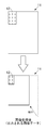
- the image data as shown in the upper figure of FIG. 6 is generated as the first image data 11.
- the first image data 11 includes the second image data 12.
- the second image data 12 is shown by a dot pattern. The same applies to the drawings referred to in the following description.
- control unit 4 After the generation of the first image data 11, the control unit 4 performs various image processing on the first image data 11. For example, density conversion processing, data format conversion processing, and the like are performed as image processing. Further, the control unit 4 performs a process of adjusting the size of the first image data 11 (width in the main scanning direction and width in the sub-scanning direction) to the size indicated by the set value of the setting item “transmission size”.
- the setting value of the setting item "transmission size” is A4 size
- the setting value of the setting item "zoom” is 100%. Therefore, the size of the first image data 11 is set to A4 size. Further, the first image data 11 is not enlarged or reduced.
- the first image data 11 after image processing is shown in the lower figure of FIG.
- control unit 4 After the image processing on the first image data 11, the control unit 4 causes the output unit 6 to output the first image data 11 after the image processing.
- the first image data 11 shown in the lower figure of FIG. 6 is output.
- the operation panel 3 accepts the output destination setting from the user.
- the control unit 4 controls the network communication unit 61 and transmits the first image data 11 after the image processing to the PC 201.
- the control unit 4 controls the USB interface unit 62 and transmits the first image data 11 after image processing to the USB device 202.
- the setting value of the setting item "original size” is set to A4 size
- the setting value of the setting item "transmission size” is set to A5 size
- the setting value of the setting item "zoom” is automatic. Suppose it is set to.
- the reading range of the image reading unit 1 is set to the range corresponding to the A4 size. Then, the image reading unit 1 reads the set reading range. As a result, as shown in the upper figure of FIG. 7, the first image data 11 including the second image data 12 (the same first image data 11 as in the first example) is generated.
- control unit 4 performs image processing on the first image data 11.
- the control unit 4 performs image processing on the first image data 11 to adjust the size of the first image data 11 to the size indicated by the set value of the setting item “transmission size”.
- the setting value of the setting item "transmission size” is A5 size
- the setting value of the setting item "zoom” is automatic. Therefore, the size of the first image data 11 is set to A5 size. Further, since the setting value of the setting item "zoom" is automatic, the first image data 11 is reduced to A5 size.
- the first image data 11 after image processing (after reduction) is shown in the lower figure of FIG. 7.
- control unit 4 After the image processing on the first image data 11, the control unit 4 causes the output unit 6 to output the first image data 11 after the image processing.
- the first image data 11 shown in the lower figure of FIG. 7 is output.
- the setting value of the setting item "original size” is set to A4 size
- the setting value of the setting item "transmission size” is set to A5 size
- the setting value of the setting item "zoom” is 100. Suppose it is set to%.
- the range corresponding to the A4 size is set as the reading range. Then, the set reading range is read. As a result, as shown in the upper figure of FIG. 8, the first image data 11 including the second image data 12 (the same first image data 11 as in the first and second examples) is generated.
- control unit 4 performs image processing on the first image data 11.
- the control unit 4 performs image processing on the first image data 11 to adjust the size of the first image data 11 to the size indicated by the set value of the setting item “transmission size”.
- the setting value of the setting item "transmission size” is A5 size
- the setting value of the setting item "zoom” is 100%. Therefore, the size of the first image data 11 is set to A5 size. Further, since the set value of the setting item "zoom” is 100%, the first image data 11 is not reduced. In this case, the trimming process for the first image data 11 is performed.
- the first image data 11 after image processing (after trimming) is shown in the lower figure of FIG. In the lower figure of FIG. 8, the trimmed region of the first image data 11 is shown by hatching.
- control unit 4 After the image processing on the first image data 11, the control unit 4 causes the output unit 6 to output the first image data 11 after the image processing.
- the first image data 11 shown in the lower figure of FIG. 8 is output.
- the first image data 11 is output.
- image data other than the second image data 12 is output together with the second image data 12.
- the image of the card manuscript CD does not exist in the image data other than the second image data 12. Therefore, no image data other than the second image data 12 is required.
- the first image data 11 is to be output.
- the multifunction device 100 is equipped with an output data selection function that outputs image data selected by the user among the first image data 11 and the second image data 12.
- the control unit 4 performs processing related to the output data selection function (hereinafter, referred to as output data selection processing). Prior to the output data selection process, the control unit 4 performs a condition determination process for determining whether or not the read start condition is satisfied.
- the control unit 4 performs the output data selection process when the output data selection function is enabled.
- the operation panel 3 receives from the user the setting of enabling / disabling the output data selection function. By enabling the output data selection function, it is possible to suppress the output of image data as shown in each of the figures below in FIGS. 6 to 8.
- the standard size original D may be set on the set surface 10S, or the irregular size original D (card original CD) may be set on the set surface 10S.
- the corner of the document D may be aligned with the reference position RP, or the corner of the document D may not be aligned with the reference position RP.
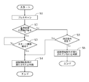
- the flowchart of FIG. 9 starts when the document cover 102 is closed (immediately before the document cover 102 is completely closed). That is, the flowchart of FIG. 9 starts when the control unit 4 detects that the document cover 102 is closed until the tilt angle of the document cover 102 reaches a predetermined angle.
- step S1 the control unit 4 causes the image reading unit 1 to perform a prescan.
- the image reading unit 1 reads a predetermined area A (see FIG. 3) including the reference position RP in the contact glass 10.
- the pre-scan reading is performed for a predetermined number of lines from the reading start line SL.
- the predetermined region A is indicated by a alternate long and short dash line.
- the reading for generating the first image data 11 is referred to as normal reading and is distinguished from pre-scan.
- step S2 the control unit 4 determines whether or not the document D is present in the reference position RP based on the image data obtained by the prescan. If the set state of the document D (card document CD) is as shown in FIG. 3, it is determined that the document D is in the reference position RP. Even if the document D is set on the set surface 10S, if the corners of the document D are not aligned with the reference position RP, it is determined that there is no document D in the reference position RP.
- control unit 4 determines that the document D is in the reference position RP, the start operation for requesting a transmission job (the operation of pressing the start button on the operation panel 3) is enabled. On the other hand, when the control unit 4 determines that the document D does not exist in the reference position RP, the start operation for requesting the transmission job is invalidated.
- step S3 the control unit 4 determines whether or not the operation panel 3 has accepted the start operation.
- step S4 determines that the start operation is not accepted, the process of step S4 is repeated.
- step S4 the control unit 4 determines that the reading start condition is satisfied. That is, when the user aligns the corner of the document D with the reference position RP, the transmission job (reading by the image reading unit 1) is started by the user performing a start operation on the operation panel 3.
- step S2 if the control unit 4 determines that there is no document D in the reference position RP, the process proceeds to step S5. That is, when the start operation for the operation panel 3 is invalidated, the process proceeds from step S2 to step S5. When the process proceeds to step S5, the control unit 4 determines whether or not the predetermined condition is satisfied.
- step S5 the process of step S5 will be specifically described.
- the control unit 4 starts measuring the time when the transmission job accompanied by the normal reading is completed. Then, when the control unit 4 determines whether or not the predetermined condition is satisfied, the elapsed time from the completion of the previous (most recent) transmission job reaches a predetermined time (for example, several tens of seconds to several minutes). Judge whether or not it is. As a result, when the elapsed time reaches the predetermined time, the control unit 4 determines that the predetermined condition is satisfied.
- a predetermined time for example, several tens of seconds to several minutes.
- the control unit 4 causes the operation panel 3 to accept a predetermined end operation as an operation for instructing the end of the transmission job.
- the operation panel 3 accepts an operation for a predetermined hardware button 32 as an end operation.
- the control unit 4 determines whether or not the operation panel 3 has accepted the end operation after the previous transmission job is completed. As a result, when the operation panel 3 accepts the end operation, the control unit 4 determines that the predetermined condition is satisfied.
- control unit 4 determines that the predetermined condition is satisfied if the elapsed time from the completion of the previous transmission job reaches the predetermined time. Further, the control unit 4 determines that the predetermined condition is satisfied if the operation panel 3 accepts the end operation even if the elapsed time from the completion of the previous transmission job has not reached the predetermined time.
- step S5 If the control unit 4 determines in step S5 that the predetermined condition is satisfied, the process proceeds to step S4. If the predetermined condition is satisfied, it is highly possible that the user opens and closes the document cover 102 in order to set the document D on the setting surface 10S. In other words, there is a high possibility that the document D is set on the set surface 10S. After the elapsed time from the completion of the previous transmission job reaches a predetermined time, or after the operation panel 3 accepts the end operation after the completion of the previous transmission job, for example, the user is in the state shown in FIG. When the document D (card document CD) is set on the set surface 10S and the document cover 102 is closed, it is determined that the predetermined conditions are satisfied.
- the predetermined condition it is satisfied, it is highly possible that the user opens and closes the document cover 102 in order to set the document D on the setting surface 10S. In other words, there is a high possibility that the document D is set on the set surface 10S. After the elapsed time from
- step S4 the control unit 4 determines that the reading start condition is satisfied. That is, even if the user does not align the corner of the document D with the reference position RP (even if the start operation for the operation panel 3 is disabled), the elapsed time from the completion of the previous transmission job has reached the predetermined time. If the operation panel 3 accepts the end operation after the completion of the previous transmission job, the transmission is automatically (forced) even if the user does not perform the start operation on the operation panel 3. The job is started. Even if the user presses the start button on the operation panel 3, the operation is not accepted as a start operation (the operation is invalid).
- step S5 determines in step S5 that the predetermined condition is not satisfied
- the process proceeds to step S6. If the predetermined condition is not satisfied, it is highly possible that the user opens and closes the document cover 102 in order to remove the document D from the set surface 10S after the transmission job is completed. In other words, there is a high possibility that the document D is not set on the set surface 10S. Therefore, when the process proceeds to step S6, the control unit 4 determines that the reading start condition is not satisfied. In this case, the transmission job (reading by the image reading unit 1) is not started.
- the start of the flowchart of FIG. 11 is when the control unit 4 determines that the reading start condition is satisfied.
- step S11 the control unit 4 sets the reading range by the image reading unit 1. Then, the control unit 4 causes the image reading unit 1 to read the set reading range. The image reading unit 1 reads the set reading range and generates the first image data 11 (image data in the reading area).
- step S12 the control unit 4 detects the size of the document D set on the set surface 10S.
- the control unit 4 recognizes the document area (the area where the image of the document D exists) in the first image data 11.
- the control unit 4 detects the contour line (edge image forming the contour line) of the document D by performing edge detection processing on the first image data 11.
- the control unit 4 recognizes the area surrounded by the contour line detected by the edge detection process as the document area.
- the control unit 4 detects the size of the document region (width in the main scanning direction and width in the sub-scanning direction) existing in the first image data 11 as the size of the document D set on the set surface 10S.
- the control unit 4 determines whether or not the detected size of the document D (hereinafter referred to as the detection size) is within a predetermined range.
- the predetermined range includes a range in the main scanning direction (hereinafter referred to as the first range) and a range in the sub-scanning direction (hereinafter referred to as the second range).
- the maximum value of the first range is 210 mm
- the minimum value of the first range is 50 mm.
- the maximum value of the second range is 210 mm
- the minimum value of the second range is 50 mm.
- the detection range is within the predetermined range.
- the control unit 4 deviates from the predetermined range if the width of the detection size in the sub-scanning direction is out of the second range.
- the control unit 4 deviates from the predetermined range if the width of the detection size in the main scanning direction is out of the first range.
- step S13 determines in step S13 that the detection size is within the predetermined range. If the detection size is within the predetermined range, it is highly possible that the ID card (card original CD) is set as the original D to be read.
- step S11 the image reading unit 1 performs a pre-scan. Therefore, when the document D is located at the reference position RP, the width of the document D set on the set surface 10S in the main scanning direction can be detected based on the image data obtained by the pre-scan. Therefore, as a modification when the document D is present at the reference position RP, the following configuration may be performed.
- the control unit 4 detects the width in the main scanning direction of the document D set on the set surface 10S based on the image data obtained by the pre-scan, and the detected width is the first range. Determine if it fits in. Then, when the control unit 4 determines that the width of the document D set on the set surface 10S in the main scanning direction is within the first range, the process proceeds to step S14.
- the control unit 4 performs a crop process for extracting the image data of the document D (the image data of the document area detected by the edge detection process) from the first image data 11. That is, the control unit 4 extracts the second image data 12 from the first image data 11.
- the control unit 4 performs a process of correcting the inclination of the image, the distortion of the image, and the like on the second image data 12 extracted by the crop process.
- step S15 the control unit 4 generates a first preview image 71 (see each of the lower figures of FIGS. 12 and 13) corresponding to the first image data 11. Further, the control unit 4 generates a second preview image (see each of the lower figures of FIGS. 12 and 13) corresponding to the second image data 12. In other words, the control unit 4 generates display data for each of the first image data 11 and the second image data 12.
- step S16 the control unit 4 causes the operation panel 3 to accept a selection operation for selecting which of the first image data 11 and the second image data 12 is to be output.
- the control unit 4 causes the operation panel 3 to display the selection screen 7 on which the first preview image 71 and the second preview image 72 are arranged, as shown in the lower figures of FIGS. 12 and 13.
- the operation panel 3 displays the selection screen 7 and accepts the selection operation from the user.
- the selection screen 7 as shown in the lower figure of FIG. 12 is displayed. Is displayed.
- the operation panel 3 accepts a touch operation (for example, a tap operation) on the display area of either the first preview image 71 or the second preview image 72 as a selection operation while the selection screen 7 is being displayed.
- a touch operation for example, a tap operation
- the control unit 4 determines that the first image data 11 is selected.
- the control unit 4 determines that the second image data 12 has been selected.
- step S17 the control unit 4 determines whether or not the first image data 11 has been selected.
- the process proceeds to step S18.
- the control unit 4 determines that the second image data 12 has been selected (the first image data 11 has not been selected)
- the process proceeds to step S19.
- step S18 the control unit 4 performs image processing on the first image data 11. Then, the control unit 4 causes the output unit 6 to output the first image data 11 after the image processing.
- step S19 the control unit 4 performs image processing on the second image data 12. Then, the control unit 4 causes the output unit 6 to output the second image data 12 after the image processing.
- step S18 If the control unit 4 determines in step S13 that the detection size is out of the predetermined range, the process proceeds to step S18.
- the fact that the detection size deviates from the predetermined size means that the document D set on the set surface 10S is not a card document CD. In other words, there is a high possibility that the standard size document D is set on the set surface 10S. In other words, there is a high possibility that the size indicated by the set value (set value set by the user) of the setting item "original size" and the size of the original D actually set on the set surface 10S match. .. Therefore, if the detection size is out of the predetermined range, the process proceeds to step S18.
- the setting value of the setting item "original size” is set to A4 size.
- the manuscript D actually set on the set surface 10S is the card manuscript CD.
- the setting position of the card document CD on the setting surface 10S is out of the range corresponding to the A4 size. This state is shown in FIG. In FIG. 14, the card original CD is indicated by a dot pattern, and the range corresponding to the A4 size is surrounded by a broken line.
- the image data (second image data 12) of the card manuscript CD will be interrupted. Therefore, when there is no document D in the reference position RP (when there is a possibility that the card document CD is set on the setting surface 10S), the entire surface of the contact glass 10 may be scanned as normal scanning.
- the compound machine 100 (image forming apparatus) of the present embodiment has an operation panel 3 for displaying an image and receiving an operation from a user, an output unit 6 for outputting image data to an external device 200, and a manuscript D. It is provided with an image reading unit 1 for normal reading that reads the contact glass 10 in which the is set and generates first image data 11 which is image data of the read region, and a control unit 4 for performing output data selection processing. When performing the output data selection process, the control unit 4 extracts the second image data 12, which is the image data of the original D, from the first image data 11.
- control unit 4 displays the first preview image 71 corresponding to the first image data 11 and the second preview image 72 corresponding to the second image data 12 on the operation panel 3, and displays the first preview image 71 and the second preview image 72.
- the operation panel 3 is made to accept the selection operation for selecting any of the preview images 72.
- the control unit 4 causes the output unit 6 to output the first image data 11.
- the control unit 4 causes the output unit 6 to output the second image data 12.
- the selection of whether to output the first image data 11 or the second image data 12 is accepted. Is done.
- the image data of the area desired by the user among the image data obtained by the normal reading.
- the user selects the second image data 12 only the image data of the original area is output from the image data of the reading area read by the image reading unit 1, and the image data of the area outside the original is not output. It is convenient for users who want to output only the image data of the original area.
- the user selects the first image data 11 the image data of the entire area of the reading area read by the image reading unit 1 is output, so that the user who wants to output the image data of the entire area of the reading area. The convenience of is not impaired.
- the first preview image 71 and the second preview image 72 are displayed, after confirming the output results of the first image data 11 and the second image data 12, the first image data 11 and the second image data D12 You can select the image data to be output. As a result, the convenience of the user is further improved.
- the control unit 4 detects the size of the document D set in the contact glass 10. Then, the control unit 4 causes the operation panel 3 to accept the selection operation when the size of the document D is within the predetermined range, and accepts the selection operation when the size of the document D is out of the predetermined range. Is not performed on the operation panel 3, but the output unit 6 is made to output the first image data 11. As a result, it is possible to prevent unnecessary selection and reception of image data to be output to the external device 200.
- the control unit 4 causes the image reading unit 1 to read (prescan) a predetermined area A including the reference position RP in the contact glass 10. Based on the image data obtained by reading the predetermined area A, it is determined whether or not the document D is present in the reference position RP. Then, when the document D is in the reference position RP, the control unit 4 causes the image reading unit 1 to perform normal reading after the operation panel 3 accepts the start operation. On the other hand, when there is no document D in the reference position RP, the control unit 4 causes the image reading unit 1 to perform normal reading even if the operation panel 3 does not accept the start operation.
- the corner of the document D may not be aligned with the reference position RP when the document D is set on the contact glass 10. Therefore, when the document cover 102 is closed, it is preferable that the document cover 102 is normally read even if the document D is not present at the reference position RP.
- the document cover 102 is also opened and closed when the user pulls out the document D from the contact glass 10. That is, the document cover 102 may be closed when the document D is not set on the contact glass 10.
- the control unit 4 detects that there is no document D in the reference position RP when the document cover 102 is closed until a predetermined condition is satisfied after the completion of normal scanning. Even so, the image reading unit 1 is not allowed to perform normal reading.
- the control unit 4 states that the predetermined condition is satisfied when the elapsed time from the completion of the normal reading reaches a predetermined time, or when the operation panel 3 accepts the end operation after the normal reading is completed. to decide.
Landscapes
- Engineering & Computer Science (AREA)
- Multimedia (AREA)
- Signal Processing (AREA)
- Human Computer Interaction (AREA)
- Facsimiles In General (AREA)
- Facsimile Scanning Arrangements (AREA)
Priority Applications (2)
| Application Number | Priority Date | Filing Date | Title |
|---|---|---|---|
| JP2021542824A JPWO2021039605A1 (https=) | 2019-08-29 | 2020-08-20 | |
| US17/638,158 US11622057B2 (en) | 2019-08-29 | 2020-08-20 | Image forming apparatus which reads and outputs image data of an area desired by a user |
Applications Claiming Priority (2)
| Application Number | Priority Date | Filing Date | Title |
|---|---|---|---|
| JP2019-156549 | 2019-08-29 | ||
| JP2019156549 | 2019-08-29 |
Publications (1)
| Publication Number | Publication Date |
|---|---|
| WO2021039605A1 true WO2021039605A1 (ja) | 2021-03-04 |
Family
ID=74685530
Family Applications (1)
| Application Number | Title | Priority Date | Filing Date |
|---|---|---|---|
| PCT/JP2020/031533 Ceased WO2021039605A1 (ja) | 2019-08-29 | 2020-08-20 | 画像形成装置 |
Country Status (3)
| Country | Link |
|---|---|
| US (1) | US11622057B2 (https=) |
| JP (1) | JPWO2021039605A1 (https=) |
| WO (1) | WO2021039605A1 (https=) |
Families Citing this family (1)
| Publication number | Priority date | Publication date | Assignee | Title |
|---|---|---|---|---|
| JP2023066121A (ja) * | 2021-10-28 | 2023-05-15 | 京セラドキュメントソリューションズ株式会社 | 画像処理システム |
Citations (2)
| Publication number | Priority date | Publication date | Assignee | Title |
|---|---|---|---|---|
| JP2002051058A (ja) * | 2000-04-20 | 2002-02-15 | Matsushita Electric Ind Co Ltd | 通信システム、車載通信システム、通信機器、及び車載機器 |
| JP2018128808A (ja) * | 2017-02-08 | 2018-08-16 | 日本電気株式会社 | 情報処理装置、情報処理方法、プログラム、情報処理システム |
Family Cites Families (8)
| Publication number | Priority date | Publication date | Assignee | Title |
|---|---|---|---|---|
| JPH08279884A (ja) | 1995-02-08 | 1996-10-22 | Ricoh Co Ltd | 画像形成装置 |
| JP2000332966A (ja) | 1999-05-17 | 2000-11-30 | Fuji Xerox Co Ltd | スキャン装置およびプレビュー画像表示方法 |
| JP2002290723A (ja) | 2001-03-28 | 2002-10-04 | Fuji Photo Film Co Ltd | 画像処理装置 |
| JP4533965B2 (ja) | 2009-07-29 | 2010-09-01 | キヤノン電子株式会社 | 画像読取装置、画像読取方法、及び記憶媒体 |
| JP6500863B2 (ja) * | 2016-09-02 | 2019-04-17 | 京セラドキュメントソリューションズ株式会社 | 画像形成装置 |
| US20190098170A1 (en) * | 2017-09-25 | 2019-03-28 | Kabushiki Kaisha Toshiba | System and method for converting a multi-object scan into discrete documents |
| JP7005290B2 (ja) * | 2017-11-07 | 2022-01-21 | シャープ株式会社 | 画像処理装置 |
| JP6930440B2 (ja) * | 2018-01-25 | 2021-09-01 | 京セラドキュメントソリューションズ株式会社 | 画像形成装置 |
-
2020
- 2020-08-20 US US17/638,158 patent/US11622057B2/en active Active
- 2020-08-20 JP JP2021542824A patent/JPWO2021039605A1/ja active Pending
- 2020-08-20 WO PCT/JP2020/031533 patent/WO2021039605A1/ja not_active Ceased
Patent Citations (2)
| Publication number | Priority date | Publication date | Assignee | Title |
|---|---|---|---|---|
| JP2002051058A (ja) * | 2000-04-20 | 2002-02-15 | Matsushita Electric Ind Co Ltd | 通信システム、車載通信システム、通信機器、及び車載機器 |
| JP2018128808A (ja) * | 2017-02-08 | 2018-08-16 | 日本電気株式会社 | 情報処理装置、情報処理方法、プログラム、情報処理システム |
Also Published As
| Publication number | Publication date |
|---|---|
| JPWO2021039605A1 (https=) | 2021-03-04 |
| US11622057B2 (en) | 2023-04-04 |
| US20220407976A1 (en) | 2022-12-22 |
Similar Documents
| Publication | Publication Date | Title |
|---|---|---|
| JP6332081B2 (ja) | 読取装置及びこれを備えた画像形成装置 | |
| CN101800826B (zh) | 图像处理装置、终端装置、打印机装置及图像处理方法 | |
| US11343398B2 (en) | Image forming apparatus, recording medium recording control program, and control method | |
| WO2021039605A1 (ja) | 画像形成装置 | |
| JP7645128B2 (ja) | 原稿読取装置、当該原稿読取装置を備える画像出力装置、原稿読取装置の制御プログラムおよび制御方法 | |
| JP3772820B2 (ja) | 画像処理装置及び画像読取装置 | |
| US10659639B2 (en) | Image reading apparatus | |
| JP5269863B2 (ja) | 画像読取制御装置、画像形成装置および画像読取方法 | |
| JP6561732B2 (ja) | 読取装置およびプログラム | |
| JP7334496B2 (ja) | 画像読取装置 | |
| JP6061903B2 (ja) | 画像読取装置及び画像形成装置 | |
| JP7505561B2 (ja) | 画像読取装置および画像形成装置 | |
| JP7511048B2 (ja) | 画像処理装置 | |
| US11936827B2 (en) | Image forming apparatus capable of performing crop processing, control method, and non-transitory computer-readable medium storing control program | |
| JP7377697B2 (ja) | 画像出力装置、画像出力装置の制御プログラムおよび制御方法 | |
| JP5029569B2 (ja) | 画像読取装置、画像読取方法、画像読取プログラム | |
| JP7176363B2 (ja) | 画像読取装置 | |
| JP7215311B2 (ja) | 画像読取り装置、画像読取り方法およびコンピュータプログラム | |
| JP6870557B2 (ja) | 画像読取装置 | |
| JP6614744B2 (ja) | スキャンサービス端末、スキャンサービスシステム、スキャン情報提供方法、及びスキャン情報提供用プログラム | |
| JP6641977B2 (ja) | 読取装置 | |
| JP2021072517A (ja) | 画像処理装置 | |
| JP2018056918A (ja) | 画像形成装置 | |
| WO2026054119A1 (ja) | 画像処理装置、画像処理方法 | |
| JP2022102190A (ja) | 画像処理装置および画像処理システム |
Legal Events
| Date | Code | Title | Description |
|---|---|---|---|
| 121 | Ep: the epo has been informed by wipo that ep was designated in this application |
Ref document number: 20857096 Country of ref document: EP Kind code of ref document: A1 |
|
| ENP | Entry into the national phase |
Ref document number: 2021542824 Country of ref document: JP Kind code of ref document: A |
|
| NENP | Non-entry into the national phase |
Ref country code: DE |
|
| 122 | Ep: pct application non-entry in european phase |
Ref document number: 20857096 Country of ref document: EP Kind code of ref document: A1 |