WO2021033567A1 - 磁性楔、回転電機、および磁性楔の製造方法 - Google Patents
磁性楔、回転電機、および磁性楔の製造方法 Download PDFInfo
- Publication number
- WO2021033567A1 WO2021033567A1 PCT/JP2020/030213 JP2020030213W WO2021033567A1 WO 2021033567 A1 WO2021033567 A1 WO 2021033567A1 JP 2020030213 W JP2020030213 W JP 2020030213W WO 2021033567 A1 WO2021033567 A1 WO 2021033567A1
- Authority
- WO
- WIPO (PCT)
- Prior art keywords
- magnetic
- particles
- wedge
- based soft
- soft magnetic
- Prior art date
- Legal status (The legal status is an assumption and is not a legal conclusion. Google has not performed a legal analysis and makes no representation as to the accuracy of the status listed.)
- Ceased
Links
Images





Classifications
-
- C—CHEMISTRY; METALLURGY
- C22—METALLURGY; FERROUS OR NON-FERROUS ALLOYS; TREATMENT OF ALLOYS OR NON-FERROUS METALS
- C22C—ALLOYS
- C22C38/00—Ferrous alloys, e.g. steel alloys
- C22C38/06—Ferrous alloys, e.g. steel alloys containing aluminium
-
- B—PERFORMING OPERATIONS; TRANSPORTING
- B22—CASTING; POWDER METALLURGY
- B22F—WORKING METALLIC POWDER; MANUFACTURE OF ARTICLES FROM METALLIC POWDER; MAKING METALLIC POWDER; APPARATUS OR DEVICES SPECIALLY ADAPTED FOR METALLIC POWDER
- B22F1/00—Metallic powder; Treatment of metallic powder, e.g. to facilitate working or to improve properties
-
- B—PERFORMING OPERATIONS; TRANSPORTING
- B22—CASTING; POWDER METALLURGY
- B22F—WORKING METALLIC POWDER; MANUFACTURE OF ARTICLES FROM METALLIC POWDER; MAKING METALLIC POWDER; APPARATUS OR DEVICES SPECIALLY ADAPTED FOR METALLIC POWDER
- B22F1/00—Metallic powder; Treatment of metallic powder, e.g. to facilitate working or to improve properties
- B22F1/16—Metallic particles coated with a non-metal
-
- B—PERFORMING OPERATIONS; TRANSPORTING
- B22—CASTING; POWDER METALLURGY
- B22F—WORKING METALLIC POWDER; MANUFACTURE OF ARTICLES FROM METALLIC POWDER; MAKING METALLIC POWDER; APPARATUS OR DEVICES SPECIALLY ADAPTED FOR METALLIC POWDER
- B22F10/00—Additive manufacturing of workpieces or articles from metallic powder
- B22F10/10—Formation of a green body
- B22F10/14—Formation of a green body by jetting of binder onto a bed of metal powder
-
- B—PERFORMING OPERATIONS; TRANSPORTING
- B22—CASTING; POWDER METALLURGY
- B22F—WORKING METALLIC POWDER; MANUFACTURE OF ARTICLES FROM METALLIC POWDER; MAKING METALLIC POWDER; APPARATUS OR DEVICES SPECIALLY ADAPTED FOR METALLIC POWDER
- B22F3/00—Manufacture of workpieces or articles from metallic powder characterised by the manner of compacting or sintering; Apparatus specially adapted therefor ; Presses and furnaces
-
- B—PERFORMING OPERATIONS; TRANSPORTING
- B22—CASTING; POWDER METALLURGY
- B22F—WORKING METALLIC POWDER; MANUFACTURE OF ARTICLES FROM METALLIC POWDER; MAKING METALLIC POWDER; APPARATUS OR DEVICES SPECIALLY ADAPTED FOR METALLIC POWDER
- B22F3/00—Manufacture of workpieces or articles from metallic powder characterised by the manner of compacting or sintering; Apparatus specially adapted therefor ; Presses and furnaces
- B22F3/02—Compacting only
-
- B—PERFORMING OPERATIONS; TRANSPORTING
- B22—CASTING; POWDER METALLURGY
- B22F—WORKING METALLIC POWDER; MANUFACTURE OF ARTICLES FROM METALLIC POWDER; MAKING METALLIC POWDER; APPARATUS OR DEVICES SPECIALLY ADAPTED FOR METALLIC POWDER
- B22F3/00—Manufacture of workpieces or articles from metallic powder characterised by the manner of compacting or sintering; Apparatus specially adapted therefor ; Presses and furnaces
- B22F3/24—After-treatment of workpieces or articles
-
- B—PERFORMING OPERATIONS; TRANSPORTING
- B22—CASTING; POWDER METALLURGY
- B22F—WORKING METALLIC POWDER; MANUFACTURE OF ARTICLES FROM METALLIC POWDER; MAKING METALLIC POWDER; APPARATUS OR DEVICES SPECIALLY ADAPTED FOR METALLIC POWDER
- B22F9/00—Making metallic powder or suspensions thereof
- B22F9/02—Making metallic powder or suspensions thereof using physical processes
- B22F9/06—Making metallic powder or suspensions thereof using physical processes starting from liquid material
- B22F9/08—Making metallic powder or suspensions thereof using physical processes starting from liquid material by casting, e.g. through sieves or in water, by atomising or spraying
- B22F9/082—Making metallic powder or suspensions thereof using physical processes starting from liquid material by casting, e.g. through sieves or in water, by atomising or spraying atomising using a fluid
-
- C—CHEMISTRY; METALLURGY
- C22—METALLURGY; FERROUS OR NON-FERROUS ALLOYS; TREATMENT OF ALLOYS OR NON-FERROUS METALS
- C22C—ALLOYS
- C22C1/00—Making non-ferrous alloys
- C22C1/04—Making non-ferrous alloys by powder metallurgy
- C22C1/05—Mixtures of metal powder with non-metallic powder
- C22C1/051—Making hard metals based on borides, carbides, nitrides, oxides or silicides; Preparation of the powder mixture used as the starting material therefor
-
- C—CHEMISTRY; METALLURGY
- C22—METALLURGY; FERROUS OR NON-FERROUS ALLOYS; TREATMENT OF ALLOYS OR NON-FERROUS METALS
- C22C—ALLOYS
- C22C38/00—Ferrous alloys, e.g. steel alloys
-
- C—CHEMISTRY; METALLURGY
- C22—METALLURGY; FERROUS OR NON-FERROUS ALLOYS; TREATMENT OF ALLOYS OR NON-FERROUS METALS
- C22C—ALLOYS
- C22C38/00—Ferrous alloys, e.g. steel alloys
- C22C38/02—Ferrous alloys, e.g. steel alloys containing silicon
-
- C—CHEMISTRY; METALLURGY
- C22—METALLURGY; FERROUS OR NON-FERROUS ALLOYS; TREATMENT OF ALLOYS OR NON-FERROUS METALS
- C22C—ALLOYS
- C22C38/00—Ferrous alloys, e.g. steel alloys
- C22C38/14—Ferrous alloys, e.g. steel alloys containing titanium or zirconium
-
- C—CHEMISTRY; METALLURGY
- C22—METALLURGY; FERROUS OR NON-FERROUS ALLOYS; TREATMENT OF ALLOYS OR NON-FERROUS METALS
- C22C—ALLOYS
- C22C38/00—Ferrous alloys, e.g. steel alloys
- C22C38/18—Ferrous alloys, e.g. steel alloys containing chromium
-
- H—ELECTRICITY
- H01—ELECTRIC ELEMENTS
- H01F—MAGNETS; INDUCTANCES; TRANSFORMERS; SELECTION OF MATERIALS FOR THEIR MAGNETIC PROPERTIES
- H01F1/00—Magnets or magnetic bodies characterised by the magnetic materials therefor; Selection of materials for their magnetic properties
- H01F1/01—Magnets or magnetic bodies characterised by the magnetic materials therefor; Selection of materials for their magnetic properties of inorganic materials
- H01F1/03—Magnets or magnetic bodies characterised by the magnetic materials therefor; Selection of materials for their magnetic properties of inorganic materials characterised by their coercivity
- H01F1/12—Magnets or magnetic bodies characterised by the magnetic materials therefor; Selection of materials for their magnetic properties of inorganic materials characterised by their coercivity of soft-magnetic materials
- H01F1/14—Magnets or magnetic bodies characterised by the magnetic materials therefor; Selection of materials for their magnetic properties of inorganic materials characterised by their coercivity of soft-magnetic materials metals or alloys
- H01F1/147—Alloys characterised by their composition
-
- H—ELECTRICITY
- H01—ELECTRIC ELEMENTS
- H01F—MAGNETS; INDUCTANCES; TRANSFORMERS; SELECTION OF MATERIALS FOR THEIR MAGNETIC PROPERTIES
- H01F1/00—Magnets or magnetic bodies characterised by the magnetic materials therefor; Selection of materials for their magnetic properties
- H01F1/01—Magnets or magnetic bodies characterised by the magnetic materials therefor; Selection of materials for their magnetic properties of inorganic materials
- H01F1/03—Magnets or magnetic bodies characterised by the magnetic materials therefor; Selection of materials for their magnetic properties of inorganic materials characterised by their coercivity
- H01F1/12—Magnets or magnetic bodies characterised by the magnetic materials therefor; Selection of materials for their magnetic properties of inorganic materials characterised by their coercivity of soft-magnetic materials
- H01F1/14—Magnets or magnetic bodies characterised by the magnetic materials therefor; Selection of materials for their magnetic properties of inorganic materials characterised by their coercivity of soft-magnetic materials metals or alloys
- H01F1/20—Magnets or magnetic bodies characterised by the magnetic materials therefor; Selection of materials for their magnetic properties of inorganic materials characterised by their coercivity of soft-magnetic materials metals or alloys in the form of particles, e.g. powder
- H01F1/22—Magnets or magnetic bodies characterised by the magnetic materials therefor; Selection of materials for their magnetic properties of inorganic materials characterised by their coercivity of soft-magnetic materials metals or alloys in the form of particles, e.g. powder pressed, sintered, or bound together
- H01F1/24—Magnets or magnetic bodies characterised by the magnetic materials therefor; Selection of materials for their magnetic properties of inorganic materials characterised by their coercivity of soft-magnetic materials metals or alloys in the form of particles, e.g. powder pressed, sintered, or bound together the particles being insulated
- H01F1/26—Magnets or magnetic bodies characterised by the magnetic materials therefor; Selection of materials for their magnetic properties of inorganic materials characterised by their coercivity of soft-magnetic materials metals or alloys in the form of particles, e.g. powder pressed, sintered, or bound together the particles being insulated by macromolecular organic substances
-
- H—ELECTRICITY
- H01—ELECTRIC ELEMENTS
- H01F—MAGNETS; INDUCTANCES; TRANSFORMERS; SELECTION OF MATERIALS FOR THEIR MAGNETIC PROPERTIES
- H01F41/00—Apparatus or processes specially adapted for manufacturing or assembling magnets, inductances or transformers; Apparatus or processes specially adapted for manufacturing materials characterised by their magnetic properties
- H01F41/02—Apparatus or processes specially adapted for manufacturing or assembling magnets, inductances or transformers; Apparatus or processes specially adapted for manufacturing materials characterised by their magnetic properties for manufacturing cores, coils, or magnets
- H01F41/0206—Manufacturing of magnetic cores by mechanical means
- H01F41/0246—Manufacturing of magnetic circuits by moulding or by pressing powder
-
- H—ELECTRICITY
- H01—ELECTRIC ELEMENTS
- H01F—MAGNETS; INDUCTANCES; TRANSFORMERS; SELECTION OF MATERIALS FOR THEIR MAGNETIC PROPERTIES
- H01F41/00—Apparatus or processes specially adapted for manufacturing or assembling magnets, inductances or transformers; Apparatus or processes specially adapted for manufacturing materials characterised by their magnetic properties
- H01F41/02—Apparatus or processes specially adapted for manufacturing or assembling magnets, inductances or transformers; Apparatus or processes specially adapted for manufacturing materials characterised by their magnetic properties for manufacturing cores, coils, or magnets
- H01F41/0253—Apparatus or processes specially adapted for manufacturing or assembling magnets, inductances or transformers; Apparatus or processes specially adapted for manufacturing materials characterised by their magnetic properties for manufacturing cores, coils, or magnets for manufacturing permanent magnets
- H01F41/0266—Moulding; Pressing
-
- H—ELECTRICITY
- H02—GENERATION; CONVERSION OR DISTRIBUTION OF ELECTRIC POWER
- H02K—DYNAMO-ELECTRIC MACHINES
- H02K1/00—Details of the magnetic circuit
- H02K1/02—Details of the magnetic circuit characterised by the magnetic material
-
- H—ELECTRICITY
- H02—GENERATION; CONVERSION OR DISTRIBUTION OF ELECTRIC POWER
- H02K—DYNAMO-ELECTRIC MACHINES
- H02K1/00—Details of the magnetic circuit
- H02K1/06—Details of the magnetic circuit characterised by the shape, form or construction
- H02K1/12—Stationary parts of the magnetic circuit
- H02K1/18—Means for mounting or fastening magnetic stationary parts on to, or to, the stator structures
- H02K1/182—Means for mounting or fastening magnetic stationary parts on to, or to, the stator structures to stators axially facing the rotor, i.e. with axial or conical air gap
-
- H—ELECTRICITY
- H02—GENERATION; CONVERSION OR DISTRIBUTION OF ELECTRIC POWER
- H02K—DYNAMO-ELECTRIC MACHINES
- H02K1/00—Details of the magnetic circuit
- H02K1/06—Details of the magnetic circuit characterised by the shape, form or construction
- H02K1/12—Stationary parts of the magnetic circuit
- H02K1/18—Means for mounting or fastening magnetic stationary parts on to, or to, the stator structures
- H02K1/185—Means for mounting or fastening magnetic stationary parts on to, or to, the stator structures to outer stators
-
- H—ELECTRICITY
- H02—GENERATION; CONVERSION OR DISTRIBUTION OF ELECTRIC POWER
- H02K—DYNAMO-ELECTRIC MACHINES
- H02K15/00—Processes or apparatus specially adapted for manufacturing, assembling, maintaining or repairing of dynamo-electric machines
- H02K15/02—Processes or apparatus specially adapted for manufacturing, assembling, maintaining or repairing of dynamo-electric machines of stator or rotor bodies
- H02K15/03—Processes or apparatus specially adapted for manufacturing, assembling, maintaining or repairing of dynamo-electric machines of stator or rotor bodies having permanent magnets
-
- H—ELECTRICITY
- H02—GENERATION; CONVERSION OR DISTRIBUTION OF ELECTRIC POWER
- H02K—DYNAMO-ELECTRIC MACHINES
- H02K15/00—Processes or apparatus specially adapted for manufacturing, assembling, maintaining or repairing of dynamo-electric machines
- H02K15/04—Processes or apparatus specially adapted for manufacturing, assembling, maintaining or repairing of dynamo-electric machines of windings prior to their mounting into the machines
-
- H—ELECTRICITY
- H02—GENERATION; CONVERSION OR DISTRIBUTION OF ELECTRIC POWER
- H02K—DYNAMO-ELECTRIC MACHINES
- H02K3/00—Details of windings
- H02K3/46—Fastening of windings on the stator or rotor structure
- H02K3/48—Fastening of windings on the stator or rotor structure in slots
- H02K3/487—Slot-closing devices
- H02K3/493—Slot-closing devices magnetic
-
- B—PERFORMING OPERATIONS; TRANSPORTING
- B22—CASTING; POWDER METALLURGY
- B22F—WORKING METALLIC POWDER; MANUFACTURE OF ARTICLES FROM METALLIC POWDER; MAKING METALLIC POWDER; APPARATUS OR DEVICES SPECIALLY ADAPTED FOR METALLIC POWDER
- B22F3/00—Manufacture of workpieces or articles from metallic powder characterised by the manner of compacting or sintering; Apparatus specially adapted therefor ; Presses and furnaces
- B22F3/24—After-treatment of workpieces or articles
- B22F2003/248—Thermal after-treatment
-
- B—PERFORMING OPERATIONS; TRANSPORTING
- B22—CASTING; POWDER METALLURGY
- B22F—WORKING METALLIC POWDER; MANUFACTURE OF ARTICLES FROM METALLIC POWDER; MAKING METALLIC POWDER; APPARATUS OR DEVICES SPECIALLY ADAPTED FOR METALLIC POWDER
- B22F2301/00—Metallic composition of the powder or its coating
- B22F2301/05—Light metals
- B22F2301/052—Aluminium
-
- B—PERFORMING OPERATIONS; TRANSPORTING
- B22—CASTING; POWDER METALLURGY
- B22F—WORKING METALLIC POWDER; MANUFACTURE OF ARTICLES FROM METALLIC POWDER; MAKING METALLIC POWDER; APPARATUS OR DEVICES SPECIALLY ADAPTED FOR METALLIC POWDER
- B22F2301/00—Metallic composition of the powder or its coating
- B22F2301/35—Iron
-
- B—PERFORMING OPERATIONS; TRANSPORTING
- B22—CASTING; POWDER METALLURGY
- B22F—WORKING METALLIC POWDER; MANUFACTURE OF ARTICLES FROM METALLIC POWDER; MAKING METALLIC POWDER; APPARATUS OR DEVICES SPECIALLY ADAPTED FOR METALLIC POWDER
- B22F2998/00—Supplementary information concerning processes or compositions relating to powder metallurgy
- B22F2998/10—Processes characterised by the sequence of their steps
-
- C—CHEMISTRY; METALLURGY
- C22—METALLURGY; FERROUS OR NON-FERROUS ALLOYS; TREATMENT OF ALLOYS OR NON-FERROUS METALS
- C22C—ALLOYS
- C22C2202/00—Physical properties
- C22C2202/02—Magnetic
-
- Y—GENERAL TAGGING OF NEW TECHNOLOGICAL DEVELOPMENTS; GENERAL TAGGING OF CROSS-SECTIONAL TECHNOLOGIES SPANNING OVER SEVERAL SECTIONS OF THE IPC; TECHNICAL SUBJECTS COVERED BY FORMER USPC CROSS-REFERENCE ART COLLECTIONS [XRACs] AND DIGESTS
- Y02—TECHNOLOGIES OR APPLICATIONS FOR MITIGATION OR ADAPTATION AGAINST CLIMATE CHANGE
- Y02P—CLIMATE CHANGE MITIGATION TECHNOLOGIES IN THE PRODUCTION OR PROCESSING OF GOODS
- Y02P10/00—Technologies related to metal processing
- Y02P10/25—Process efficiency
Definitions
- the present invention relates to a magnetic wedge used in a magnetic circuit of a rotary electric machine, a rotary electric machine using the magnetic wedge, and a method for manufacturing the magnetic wedge.
- a stator hereinafter referred to as a stator
- a rotor rotor
- a stator and a rotor (rotor) are arranged coaxially, and a plurality of teeth wound with a coil are arranged at equal intervals in the circumferential direction on a stator around the rotor. It is arranged in.
- a magnetic wedge may be arranged at the rotor-side tip of the tooth so as to connect the tips of adjacent teeth. In this case, unlike the coil parts and the like, the magnetic wedge is used without winding the coil around the magnetic wedge itself.
- the magnetic flux reaching the coil from the rotor can be magnetically shielded, and the eddy current loss of the coil can be suppressed. Further, by arranging the magnetic wedge, the magnetic flux distribution in the gap between the stator and the rotor (particularly the magnetic flux distribution in the circumferential direction) can be smoothed, and the rotation of the rotor can be smoothed. By arranging the magnetic wedges in this way, a highly efficient and high-performance rotary electric machine can be obtained.
- Patent Document 1 As a conventional magnetic wedge, one in which iron powder and glass cloth are solidified with an epoxy resin is known (for example, Patent Document 1). This magnetic wedge increases the electrical resistance by separating the iron powder particles with an epoxy resin, and increases the strength by dispersing the glass cloth.
- Patent Document 2 a magnetic wedge obtained by solidifying Fe—Si alloy powder with a resin is known (for example, Patent Document 2).
- the magnetic wedge is desired to have a high relative magnetic permeability in order to magnetically shield the coil well, and to have a high electric resistance in order to suppress the eddy current loss due to the alternating magnetic field of the coil and the rotor. There is. In addition, since bending stress is applied to the magnetic wedge arranged in the rotary electric machine by the AC magnetic field, it is desired that the bending strength is high.
- Patent Document 1 electrical resistivity 10 3 [Omega] cm or so, three-point bending strength 25 kgf / mm 2 approximately of the magnetic wedge is disclosed. However, in order to meet the demands of low loss and high reliability, further high resistance and high strength have been desired.
- the magnetic wedge of Patent Document 2 also has a high relative magnetic permeability and a good magnetic shielding property, but since the alloy powder is only solidified with a resin, there is a problem in reliability such as bending strength.
- the present invention provides a magnetic wedge having high electrical resistance and bending strength, a rotary electric machine using the magnetic wedge, and a method for manufacturing the magnetic wedge.
- the magnetic wedge of the present invention has a plurality of Fe-based soft magnetic particles and has a plurality of Fe-based soft magnetic particles.
- the plurality of Fe-based soft magnetic particles contain an element M that is more easily oxidized than Fe, and are bound by an oxide phase containing the element M.
- the element M is preferably at least one of Al, Si, Cr, Zr, and Hf.
- the magnetic wedge is preferably Fe—Al—Cr based alloy particles.
- the magnetic wedge has an electrically insulating coating formed on its surface.
- the rotary electric machine of the present invention uses any of the above magnetic wedges.
- the method for producing a magnetic wedge of the present invention includes a step of mixing Fe-based soft magnetic particles containing an element M, which is more easily oxidized than Fe, and a binder to form a mixture, and pressure molding the mixture.
- the step of forming a molded body and the heat treatment of the molded body are performed to form a surface oxide phase of the Fe-based soft magnetic particles that bind the Fe-based soft magnetic particles to each other between the particles of the Fe-based soft magnetic particles. It has a step of making it into a compacted body.
- the present invention it is possible to provide a magnetic wedge having high electric resistance and bending strength, a rotary electric machine using the magnetic wedge, and a method for manufacturing the magnetic wedge.
- the magnetic wedge of the present invention has a plurality of Fe-based soft magnetic particles, and the plurality of Fe-based soft magnetic particles contain an element M that is more easily oxidized than Fe and have an oxide phase containing the element M. It is tied up.
- the magnetic wedge 100 has, for example, a strip shape having a rectangular cross section. Then, as will be described in a later embodiment, the magnetic wedge 100 is arranged on the rotary electric machine so as to connect the rotor side tip of the tooth, and the strip is arranged so that the longitudinal direction of the strip is parallel to the rotation axis of the rotary electric machine. To.
- the shape of the magnetic wedge 100 changes depending on the connection mode with the teeth, and a step or taper may be provided on the longitudinal ridgeline or a notch may be provided, and the cross section may be polygonal, for example, a trapezoid. It may be square or irregular.
- the approximate dimensions of the magnetic wedge 100 are, for example, 20 mm to 300 mm in the longitudinal direction, 2 mm to 20 mm in the width direction (magnetic path direction), and 1 to 5 mm in thickness.
- FIG. 2 is an enlarged schematic view of a cross section of the magnetic wedge 100 of the present embodiment.
- the magnetic wedge 100 is composed of a plurality of Fe-based soft magnetic particles, and more specifically, is a compacted body of a plurality of Fe-based soft magnetic particles 1 containing an element M that is more easily oxidized than Fe.
- the compacted particles have voids 2 and a surface oxide phase 3 of Fe-based soft magnetic particles that bind Fe-based soft magnetic particles 1 to each other.
- Such a surface oxide phase is an oxide phase containing the element M.
- the Fe-based soft magnetic particles 1 are soft magnetic alloy particles having the highest Fe content in terms of mass ratio compared to other elements, and may be soft magnetic alloy particles containing Co or Ni. However, the content of Co and Ni must not exceed the content of Fe.
- the average maximum diameter of each of the Fe-based soft magnetic particles 1 is preferably 0.5 ⁇ m or more and 15 ⁇ m or less, and 0.5 ⁇ m or more and 8 ⁇ m or less. Is more preferable. Further, the particle number ratio having a maximum diameter of more than 40 ⁇ m is preferably less than 1.0%.
- the average of the maximum diameters of each of the Fe-based soft magnetic particles 1 referred to here is 30 or more particles existing in a field of view of a certain area after polishing the cross section of the magnetic wedge 100 and observing with a microscope. It is the average value of those readings of the maximum diameter of.
- the voids 2 and the surface oxide phase 3 are present between the particles of the Fe-based soft magnetic particles 1 to widen the average particle spacing of the Fe-based soft magnetic particles 1 and increase the electric resistance of the magnetic wedge 100. Can be done.
- the relative magnetic permeability of the magnetic wedge 100 can be adjusted by adjusting the volume ratio of the void 2 and the surface oxide phase 3 to the entire magnetic wedge. In other words, the volume ratio of the voids 2 and the surface oxide phase 3 to the entire magnetic wedge and the volume ratio of the Fe-based soft magnetic particles 1 (hereinafter referred to as the space factor) have a complementary relationship. By adjusting the space factor of the Fe-based soft magnetic particles 1, the relative magnetic permeability of the magnetic wedge 100 can also be adjusted.
- the space factor is defined as the ratio (relative density) of the density of the magnetic wedge 100 to the true density of the Fe-based soft magnetic particles 1.
- the space factor can be adjusted by the molding pressure of the mixture or the heat treatment temperature of the molded product, as will be described in a later embodiment.
- the relative magnetic permeability is defined by dividing the value (unit: T) of the magnetic flux density at an applied magnetic field of 160 kA / m by the magnetic field value (that is, 160 kA / m) in the DC BH curve of the magnetic wedge 100, and further vacuuming. It is a value ⁇ divided by the magnetic permeability (4 ⁇ ⁇ 10-7 H / m) of. Further, as the relative magnetic permeability, a magnetization curve measured at an excitation level of 1/10 or less of the saturation magnetic flux density of the magnetic wedge 100 and at a frequency (including DC) of 1/10 or less of the natural resonance frequency of the magnetic wedge 100.
- the value ⁇ i obtained by dividing the inclination of (so-called minor loop) by the magnetic permeability of the vacuum (4 ⁇ ⁇ 10-7 H / m) is used.
- the natural resonance frequency is a frequency at which the imaginary part of the relative magnetic permeability becomes the maximum, and when a plurality of maximums appear, the frequency on the lowest frequency side is adopted.
- the thickness of the magnetic wedge 100 can be, for example, 3 mm or less.
- the relative magnetic permeability ⁇ of the magnetic wedge 100 is preferably 4 or more (5 or more in ⁇ i). More preferably, it is 7 or more (10 or more in ⁇ i).
- the space factor of the Fe-based soft magnetic particles 1 in the magnetic wedge 100 is preferably 30% or more, and more preferably 50% or more.
- the thickness of the magnetic wedge 100 is preferably 0.5 mm or more, more preferably 1 mm or more. Even if the thickness of the magnetic wedge 100 is 1 mm or more, the relative magnetic permeability ⁇ of the magnetic wedge 100 is adjusted to 8.0 or less (65 or less in ⁇ i) in order to suppress the torque decrease of the rotary electric machine. Is preferable, and it is more preferable that the value is adjusted to 7.5 or less (50 or less in ⁇ i). And it is more preferable that it is adjusted to 7.0 or less (35 or less in ⁇ i). For that purpose, the space factor of the Fe-based soft magnetic particles 1 in the magnetic wedge 100 is preferably less than 90%, more preferably 85% or less. And it is more preferably 80% or less.
- the Fe-based soft magnetic particles 1 are particles containing an element M that is more easily oxidized than Fe.
- element M that is more easily oxidized than Fe means an element having a standard Gibbs energy of oxide lower than Fe 2 O 3.
- An element satisfying this condition can be selected as the element M, but it is preferably selected from Al, Si, Cr, Zr, and Hf because it has little radical reactivity and toxicity and it is easy to manufacture the magnetic wedge 100.
- Such a surface oxide phase 3 is chemically stable and has a high electric resistance, and strongly adheres to the Fe-based soft magnetic particles 1 to form a strong surface oxide phase. That is, the Fe-based soft magnetic particles 1 can be separated from each other to form a magnetic wedge 100 having a high electrical resistance, and the Fe-based soft magnetic particles 1 can be firmly bonded to each other to form a magnetic wedge 100 having a high bending strength. Can be done.
- the value of the volume resistivity is preferably 10 ⁇ ⁇ m or more, more preferably 20 ⁇ ⁇ m or more, and further 100 ⁇ ⁇ m or more. Is preferable. And it is more preferable that it is 1000 ⁇ ⁇ m or more.
- the higher the bending strength of the magnetic wedge 100 is, the more preferable it is, and the value of the three-point bending strength is preferably 150 MPa or more, more preferably 200 MPa or more. And it is more preferable that it is 250 MPa or more.
- the thickness of the surface oxide phase 3 is preferably set to, for example, 0.01 to 1.0 ⁇ m. By doing so, it is possible to obtain a magnetic wedge 100 having high electrical resistance and bending strength and having an adjusted relative magnetic permeability.
- the amount of the element M contained in the Fe-based soft magnetic particles 1 is too small, even if the Fe-based soft magnetic particles 1 are oxidized, the content of the element M is higher than that inside the Fe-based soft magnetic particles 1. It becomes difficult to form a high and good surface oxide phase 3, and if it is too large, the Fe concentration is reduced, so that the saturation magnetic flux density and the Curie temperature of the Fe-based soft magnetic particles 1 may decrease.
- the amount of the element M contained in the Fe-based soft magnetic particles 1 is preferably 1.0% by mass or more and 20% by mass or less. By doing so, a good surface oxide phase 3 can be easily formed, and the saturation magnetic flux density and the Curie temperature of the Fe-based soft magnetic particles 1 can be maintained high. That is, the magnetic wedge 100 having high electrical resistance and bending strength and high magnetic shielding property can be obtained.
- the element M is not limited to one type, and two or more types may be selected by combining Al and Cr, Si and Cr, and the like.
- two types of Al and Cr may be selected, and the Fe-based soft magnetic particles 1 may be Fe—Al—Cr-based alloy particles.
- the Fe—Al—Cr alloy is an alloy in which the elements having the next highest content after Fe are Cr and Al (in no particular order), and other elements are contained in a smaller amount than Fe, Cr, and Al. You may be.
- the composition of the Fe—Al—Cr alloy is not particularly limited, but for example, the Al content is preferably 2.0% by mass or more, and more preferably 5.0% by mass or more. From the viewpoint of obtaining a high saturation magnetic flux density, the Al content is preferably 10.0% by mass or less, more preferably 6.0% by mass or less.
- the Cr content is preferably 1.0% by mass or more, more preferably 2.5% by mass or more. From the viewpoint of obtaining a high saturation magnetic flux density, the Cr content is preferably 9.0% by mass or less, more preferably 4.5% by mass or less.
- the total content thereof is preferably 1.0% by mass or more and 20% by mass or less, as in the case of selecting one kind.
- the Fe-based soft magnetic particles 1 may be particles to which an element other than the element M is added. However, it is preferable to add these additive elements in a smaller amount than the element M. Further, the particles may be surface-treated by a chemical method or heat treatment. Further, the Fe-based soft magnetic particles 1 can also be composed of a plurality of types of Fe-based soft magnetic particles having different compositions.
- the surface oxide phase 3 may be a surface oxide phase 3 containing Fe or other elements in addition to the element M, and the concentration of the elements such as the element M and Fe is not necessarily set inside the surface oxide phase 3. It does not have to be uniform. That is, the element concentration may be different for each grain boundary.
- the magnetic wedge 100 having the Fe-based soft magnetic particles 1 and the surface oxide phase 3 can be used to obtain the magnetic wedge 100 having high electrical resistance and bending strength. Then, with these configurations and the void 2, the magnetic wedge 100 having high electric resistance and bending strength and having an adjusted relative magnetic permeability can be obtained.
- the resin softens and the bonding strength decreases. There is a possibility that it will end up. That is, when used at a high temperature such as a rotary electric machine, there is a possibility that a problem may occur in bending strength.
- the magnetic wedge 100 of the present embodiment since the particles are bonded to each other by the surface oxide phase 3 instead of the resin, it is possible to suppress a decrease in the binding strength between the particles at a high temperature, and the temperature is high. A magnetic wedge 100 having high bending strength can be provided even below.
- the rate of decrease in the three-point bending strength when the temperature is raised from room temperature (25 ° C.) to 150 ° C. can be less than 5%, more preferably less than 3%.
- the rate of decrease in the three-point bending strength when the temperature is raised from room temperature (25 ° C.) to 200 ° C. can be less than 10%, more preferably less than 5%.
- the magnetic wedge 100 of the present embodiment since the conventional magnetic wedge contains a resin, there is a problem that the resin is decomposed and deteriorated when exposed to a high temperature environment for a long time, causing an irreversible decrease in strength and size. ..
- the resinless magnetic wedge 100 of the present embodiment such a problem does not occur.
- the magnetic wedge 100 having excellent heat resistance and long-term reliability can be provided.
- the mass weight loss rate after 1000 hours at 180 ° C. can be less than 0.05%, more preferably less than 0.03%.
- the mass weight loss rate after 450 hours at 220 ° C. can be less than 0.1%, more preferably less than 0.05%.
- the mass weight loss rate after 240 hours at 290 ° C. can also be less than 1%, more preferably less than 0.5%.
- the heat resistant temperature of the rotary electric machine varies depending on the application and specifications, there are some that are set to 155 ° C. or 180 ° C. according to the standard. In addition, in some rotary electric machines, the temperature rises to about 200 ° C. Since the magnetic wedge 100 of the present embodiment can maintain excellent bending strength even at a high temperature, a rotary electric machine having a maximum temperature of more than 180 ° C., and further rotation of more than 200 ° C. It can also be suitably used for electric machines.
- the compacted body is used as a substrate and an electrically insulating coating is formed on the surface thereof.
- an electrically insulating coating with a resin or an oxide is preferable in order to suppress eddy current loss.
- powder coating with an epoxy resin, a pore-sealing coating by impregnation with a varnish or a silicon resin, or a metal alkoxide is used.
- the sealing treatment coating of an inorganic substance by impregnating and using a sol-gel method.
- the sealing treatment coating of the inorganic substance by the sol-gel method is particularly preferable.
- the magnetic wedge 200 which is the second embodiment of the present invention. Since the magnetic wedge 200 of the present embodiment and the magnetic wedge 100 of the first embodiment differ only in the particle composition of the compacted body, they will be described only with reference to an enlarged schematic diagram. Further, since the same configuration as that of the first embodiment has the same action and effect, the same symbols are added and the description thereof will be omitted.
- FIG. 3 is an enlarged schematic view of the magnetic wedge 200.
- the magnetic wedge 200 is a compacted body of a plurality of Fe-based soft magnetic particles 1 containing an element M that is more easily oxidized than Fe, and a plurality of non-magnetic particles 4.
- the plurality of Fe-based soft magnetic particles are bound by an oxide phase containing the element M.
- the non-magnetic particles 4 are non-magnetic particles, and the term "non-magnetic” here means that they are not ferromagnetic at room temperature. Specifically, it means particles exhibiting paramagnetic, diamagnetic, or antiferromagnetic magnetism at room temperature. Further, the non-magnetic particles 4 may be a metal or a non-metal such as an oxide.
- the non-magnetic particles 4 are present between the particles of the Fe-based soft magnetic particles 1, the average particle spacing of the Fe-based soft magnetic particles 1 is widened, and the relative magnetic permeability of the magnetic wedge 200 is due to the demagnetic field effect. Can be lowered. That is, by adjusting the content of the non-magnetic particles 4, the magnetic wedge 200 having an adjusted relative magnetic permeability can be obtained.
- the average of the maximum diameters of the non-magnetic particles 4 is preferably 0.5 ⁇ m or more and 15 ⁇ m or less, and more preferably 0.5 ⁇ m or more and 8 ⁇ m or less. preferable. Further, the particle number ratio having a maximum diameter of more than 40 ⁇ m is preferably less than 1.0%. By doing so, it is possible to obtain the magnetic wedge 200 in which the relative magnetic permeability is adjusted while maintaining the strength.
- the average particle size of the non-magnetic particles 4 is preferably smaller than the average particle size of the Fe-based soft magnetic particles 1. By doing so, the non-magnetic particles 4 can easily enter between the particles of the Fe-based soft magnetic particles 1, the distance between the particles of the Fe-based soft magnetic particles 1 becomes more uniform, and the magnetic wedge exhibits stable magnetic characteristics. It can be 200.
- the type of the non-magnetic particles 4 is not particularly limited, but it is preferably particles containing an element M contained in the Fe-based soft magnetic particles 1, that is, an element M that is more easily oxidized than Fe.
- the element M selected from Al, Si, Cr, Zr, and Hf can be contained.
- a good surface oxide phase similar to the surface of the Fe-based soft magnetic particle 1 can be formed on the surface of the non-magnetic particle 4, and the Fe-based soft magnetic particle 1 and the non-Fe-based soft magnetic particle 1 can be formed.
- the particles of the magnetic powder 2 or the particles of the non-magnetic powder 2 can be firmly bonded to each other to form a magnetic wedge 200 having a high bending strength.
- the particles of the Fe-based soft magnetic particles 1 can be isolated from each other to form a magnetic wedge 200 having a high electric resistance.
- the surface oxide phase 5 is formed by joining and integrating the surface oxide phase 3 of the Fe-based soft magnetic particles 1 and the surface oxide phase of the non-magnetic particles 4, and the components differ depending on the adjacent particles. Become a phase.
- the surface oxide phase 5 can be made into a more homogeneous surface oxide phase 5 mainly composed of the element M. it can.
- the particles of the Fe-based soft magnetic particles 1 and the non-magnetic powder 2 can be firmly bonded to each other to form a magnetic wedge 200 having high bending strength.
- the non-magnetic particles 4 may be particles of the element M alone, oxide particles containing the element M, or alloy particles containing the element M.
- Fe-based alloy particles it is preferable to use Fe-based alloy particles, increase the concentration of element M more than Fe-based soft magnetic particles, and keep the Curie temperature of the particles below room temperature, preferably -20 ° C or below. Is preferable. Then, it is more preferable to keep the temperature below -100 ° C.
- the Fe-based alloy particles are preferably metal particles containing at least one of Al and Cr, and two types of elements M, Al and Cr, are selected to form Fe—Al—Cr alloy particles. Is more preferable. By doing so, a good surface oxide phase 5 can be formed, and a magnetic wedge 200 having high bending strength can be obtained.
- the magnetic wedge 200 of the present embodiment is a magnetic wedge 200 having high electric resistance and bending strength and adjusted relative magnetic permeability, but by having the non-magnetic particles 4, The average particle spacing of the Fe-based soft magnetic powder 1 can be adjusted without increasing the voids 2 between the particles. As a result, the magnetic wedge 200 having an adjusted relative magnetic permeability can be obtained without impairing the bending strength. Therefore, when the magnetic wedge 100 of the first embodiment cannot achieve the desired specifications in terms of strength and the like, the magnetic wedge 200 of the present embodiment is effective.
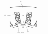
- FIG. 4 is a schematic view of the rotary electric machine 300, showing a cross-sectional structure perpendicular to the rotation axis of the rotary electric machine 300.
- the rotary electric machine 300 is a radial gap type rotary electric machine, and the stator 31 and the rotor 32 are arranged coaxially.
- a plurality of teeth 34 around which the coil 33 is wound are arranged on the stator 31 at equal intervals in the circumferential direction.
- the magnetic wedge 100 of the first embodiment or the magnetic wedge 200 of the second embodiment is arranged so as to connect the tips of adjacent teeth 34 to the tip of the teeth 34 on the rotor 32 side. doing.
- the relative permeability and saturation magnetic flux density of the teeth 34 are usually designed to be higher than those of the magnetic wedge 100 or 200.
- the magnetic flux from the rotor 32 that has reached the magnetic wedge 100 or 200 flows into the teeth 34 via the magnetic wedge 100 or 200, and the magnetic flux that reaches the coil is suppressed, reducing the eddy current loss that occurs in the coil. can do.
- most of the magnetic flux in the teeth 34 generated by the coil current flows into the rotor 32 with a gap, but a part of the magnetic flux is attracted by the magnetic wedge and spreads in the circumferential direction. Become.
- the magnetic flux distribution in the gap between the stator 31 and the rotor 32 becomes gentle.
- a rotary electric machine in which a permanent magnet is arranged in the rotor 32, cogging can be suppressed, and an eddy current generated in the rotor 32 can be suppressed.
- the loss can be reduced.
- an induction type rotary electric machine in which a cage-shaped conductor is arranged on the rotor 32, secondary copper loss can be reduced.
- the thickness of the magnetic wedge 100 or 200 (diameter dimension of the rotary electric machine) can be appropriately set in consideration of the relative magnetic permeability as described above, but if it is too thin, the strength will decrease and the magnetic wedge will be used as a magnetic wedge.
- the thickness is preferably 1 mm or more because the effect is also weakened.
- the thickness is preferably 5 mm or less, more preferably 3 mm or less, and even more preferably 2 mm or less.
- the width of the magnetic wedge 100 or 200 (dimensions in the circumferential direction of the rotary electric machine) is appropriately set according to the distance between the adjacent teeth 34, but is preferably in the range of 2 mm to 20 mm.
- the length of the magnetic wedge 100 or 200 (the axial dimension of the rotary electric machine) is also basically set appropriately according to the thickness (axial length) of the stator 31, but if it is too long, the manufacturing itself is difficult. In addition to this, it becomes easy to break when attached to a rotary electric machine, and workability deteriorates. Therefore, the length is preferably 300 mm or less, more preferably 200 mm or less, and even more preferably 100 mm or less. On the other hand, if it is too short, the work becomes complicated when it is attached to the rotary electric machine, which is not preferable. From this point of view, the length is preferably 25 mm or more, more preferably 50 mm or more.
- the cross-sectional shape of the magnetic wedge 100 or 200 is not limited to a rectangle, and may be various shapes.
- the cross-sectional shape of the magnetic wedge 100 or 200 may be a convex shape and arranged as shown in the figure. ..
- the thickness of the magnetic wedge 100 or 200 can be changed in the width direction. In this case, it is preferable that the cross-sectional shape is such that the vicinity of the center in the width direction is relatively thin.
- FIG. 7 is a process flow of the present embodiment, which is a process flow of manufacturing the magnetic wedge 100 of the first embodiment.
- the Fe-based soft magnetic powder and the binder are mixed to form a mixture S11, the mixture is pressure-molded to form a molded body S12, and the molded body is heat-treated to form a magnetic wedge 100. It has a step S13 to make a body.
- the Fe-based soft magnetic powder and the binder are mixed to form a mixture.
- the Fe-based soft magnetic powder used in step S11 is a powder that becomes Fe-based soft magnetic particles 1 in the magnetic wedge 100. It is a soft magnetic alloy powder mainly containing Fe, and a soft magnetic powder containing Co and Ni may be used. In the following description, the particles of Fe-based soft magnetic powder may be referred to as Fe-based soft magnetic particles 1.
- the Fe-based soft magnetic powder it is preferable to use a powder having an average particle size (median diameter d50 in the cumulative particle size distribution) of 1 ⁇ m or more and 100 ⁇ m or less, and more preferably 5 ⁇ m or more and 30 ⁇ m or less.
- a magnetic wedge 100 having Fe-based soft magnetic particles 1 having a preferable average particle size can be produced.
- the Fe-based soft magnetic powder a powder containing an element M that is more easily oxidized than Fe is used, and the element M is preferably selected from, for example, Al, Si, Cr, Zr, and Hf.
- the element M is preferably selected from, for example, Al, Si, Cr, Zr, and Hf.
- the amount of element M contained in the Fe-based soft magnetic powder is preferably 1.0% by mass or more and 20% by mass or less. By doing so, it is possible to easily manufacture the magnetic wedge 100 having high electric resistance and bending strength and high magnetic shielding property.
- the element M may be selected not only by one type but also by two or more types.
- two types of Al and Cr may be selected and the Fe-based soft magnetic powder may be an Fe—Al—Cr based alloy powder.
- the Fe—Al—Cr alloy is an alloy in which the elements having the next highest content after Fe are Cr and Al (in no particular order), and other elements are contained in a smaller amount than Fe, Cr, and Al. It may be.
- the total content thereof is preferably 1.0% by mass or more and 20% by mass or less, as in the case of selecting one kind.
- the Fe-based soft magnetic powder a powder to which an element other than the above element M is added may be used. However, it is preferable to add these additive elements in a smaller amount than the element M. Further, a powder containing particles surface-treated by a chemical method or heat treatment may be used.
- the Fe-based soft magnetic powder a powder prepared by a gas atomizing method or a water atomizing method can be used as a granular powder having good moldability. Further, as a flat powder for the purpose of utilizing shape anisotropy, a powder prepared by a pulverization method can be used.
- the binder is used to temporarily bond the particles to each other in step S12 to impart a certain degree of strength to the molded product.
- the binder also has the role of providing an appropriate spacing between the particles.
- an organic binder such as polyvinyl alcohol or acrylic can be used.
- a known mixing method and mixer can be used as the mixing method in step S11.
- a mixture of Fe-based soft magnetic powder and a binder may become agglomerated powder having a wide particle size distribution due to the adhesive action of the binder.
- the mixed powder may be passed through a sieve using, for example, a vibrating sieve to obtain granulated powder having a desired secondary particle size, and then used in step S12.
- a lubricant such as stearic acid or stearate may be added to the mixture in order to reduce the friction between the powder and the mold in step S12.
- the addition amount is preferably 0.1 to 2.0 parts by weight with respect to 100 parts by weight of the mixed powder.
- the lubricant may not be added to the mixture in step S11, but may be applied to the mold in step S12.
- step S12 the mixture obtained in step S11 is pressure-molded.
- a press machine and a molding die can be used.
- the pressure molding may be room temperature molding or warm molding in which the binder is heated to the extent that it does not disappear.
- step S13 the molded body obtained in step S12 is heat-treated to form a compacted body that becomes a magnetic wedge.
- step S13 by heat-treating the molded body, the binder existing between the particles of the Fe soft magnetic particles 1 of the molded body is thermally decomposed to form voids between the particles, and further the heat treatment is continued to perform Fe.
- the voids 2 and the surface oxide phase 3 of the Fe-based soft magnetic particles 1 that bind the Fe-based soft magnetic particles 1 to each other are formed between the particles of the base soft magnetic particles 1.
- the heat treatment can be performed in an atmosphere in which oxygen is present, such as in the atmosphere or in a mixed gas of oxygen and an inert gas. It can also be performed in an atmosphere in which water vapor is present, such as in a mixed gas of water vapor and an inert gas.
- the heat treatment is performed by heating the particles of the Fe-based soft magnetic particles 1 to a temperature at which the voids 2 and the surface oxide phase 3 of the Fe-based soft magnetic particles 1 that bind the Fe-based soft magnetic particles 1 to each other can be formed. And do it.
- the heat treatment temperature is preferably in the range of 600 ° C. to 900 ° C., and more preferably in the range of 700 to 800 ° C.
- the relative magnetic permeability of the magnetic wedge 100 can be adjusted by adjusting the molding load in step S12. For example, by reducing the molding load, the space factor of the Fe-based soft magnetic particles 1 in the molded body, that is, the space factor of the consolidated body after step S13 can be reduced. As a result, the average particle spacing of the Fe-based soft magnetic particles 1 in the consolidated body is widened, and the relative magnetic permeability of the magnetic wedge 100 can be adjusted to be low. From this point of view, the molding pressure is preferably less than 1.0 GPa, more preferably 0.7 GPa or less.
- the relative magnetic permeability of the magnetic wedge 100 can be adjusted by adjusting the heat treatment temperature in step S13. For example, by lowering the heat treatment temperature, the amount of the surface oxide phase 3 formed between the particles of the Fe-based soft magnetic particles 1 of the molded body is reduced, and the amount of the voids 2 of the consolidated body after the step S13 is increased. Then, the relative magnetic permeability of the magnetic wedge 100 can be adjusted.
- the grain size of the Fe-based soft magnetic alloy powder 1 in step S11 may be adjusted to adjust the relative magnetic permeability of the magnetic wedge 100.
- the soft magnetic alloy powder 1 having a smaller average particle size the influence of the demagnetic field generated on the Fe-based soft magnetic particles 1 of the molded body is strengthened, and the relative magnetic permeability of the magnetic wedge 100 is adjusted to be low. be able to.
- FIG. 8 is a process flow of the present embodiment, which is a process flow of manufacturing the magnetic wedge 200 of the second embodiment.
- This step flow includes a step S21 of mixing an Fe-based soft magnetic powder, a non-magnetic powder, and a binder to form a mixture, a step S22 of press-molding the mixture to form a molded body, and a step of heat-treating the molded body to make it magnetic. It has a step S23 of forming a compacted body to be a wedge 200.
- step S21 the Fe-based soft magnetic powder, the non-magnetic powder, and the binder are mixed to form a mixture.
- the Fe-based soft magnetic powder provided in step S21 is a powder that becomes Fe-based soft magnetic particles 1 in the magnetic wedge 200, and is the same as the Fe-based soft magnetic powder described in the fourth embodiment.
- the particles of Fe-based soft magnetic powder may be referred to as Fe-based soft magnetic particles 1
- the particles of non-magnetic powder may be referred to as non-magnetic particles 4.
- the non-magnetic powder it is preferable to use a powder having an average particle size (median diameter d50 in the cumulative particle size distribution) of 1 ⁇ m or more and 80 ⁇ m or less, and more preferably 3 ⁇ m or more and 20 ⁇ m or less.
- a magnetic wedge 200 having non-magnetic particles 4 having a preferable average particle size can be produced.
- the non-magnetic powder it is preferable to use a powder smaller than the average particle size of the Fe-based soft magnetic powder. By doing so, when the mixture is prepared, the non-magnetic particles 4 are easily dispersed between the particles of the Fe-based soft magnetic particles 1, and the inter-particle distance of the Fe-based soft magnetic particles 1 is made more uniform and stable.
- the magnetic wedge 200 exhibiting the above-mentioned magnetic properties can be easily manufactured.
- the non-magnetic powder a powder containing an element M contained in the Fe-based soft magnetic powder, that is, an element M that is more easily oxidized than Fe is used, and the element M is, for example, Al, Si, Cr, Zr, Hf. It is preferable to select from. By doing so, the magnetic wedge 200 having high bending strength can be easily manufactured.
- the non-magnetic powder a powder of element M alone may be used, or an alloy powder containing element M may be used.
- an alloy powder it is preferable to use an Fe-based alloy powder and a powder having a high content of element M so that the Curie temperature is below room temperature.
- the Fe-based alloy powder for example, two kinds of elements M, Al and Cr, may be selected, and Fe—Al—Cr based alloy powder may be used. By doing so, the magnetic wedge 200 having high bending strength can be easily manufactured.
- non-magnetic powder a powder to which an element other than the above element M is added may be used. Further, a powder containing particles surface-treated by a chemical method or heat treatment may be used.
- non-magnetic powder a powder prepared by a gas atomizing method or a water atomizing method can be used as a granular powder having good moldability. Further, as a flat powder for the purpose of utilizing shape anisotropy, a powder produced by a pulverization method can be used.
- an organic binder such as polyvinyl alcohol or acrylic may be used in order to temporarily bond the particles to each other at appropriate intervals and impart strength to the molded product. it can. Further, it is preferable to add the binder in an amount that is sufficiently thermally decomposed in the step S23 while sufficiently spreading the binder throughout the mixture and ensuring sufficient strength of the molded product. For example, it is preferable to add only 0.5 to 3.0 parts by weight with respect to 100 parts by weight of the combined Fe-based soft magnetic powder and non-magnetic powder.
- step S21 the same mixing method as in step S11 of the fourth embodiment can be used. The same applies to the amount of lubricant added.
- step S22 the mixture obtained in step S21 is pressure-molded.
- the same pressure molding as in step S12 of the fourth embodiment can be used.
- step S23 the molded body obtained in step S22 is heat-treated to form a compacted body that becomes a magnetic wedge. If metal non-magnetic particles 4 are used as the non-magnetic particles 4, the non-magnetic particles 4 may be plastically deformed when a compacted body is formed, which may increase the strength of the magnetic wedge 200. is there.
- step S23 the molded body is heat-treated to thermally decompose the binder existing between the particles in the molded body to form voids 6 between the particles, and further heat treatment is continued to form these particles between the particles.
- the surface oxide phase 5 of these particles that bind to each other is formed.
- the same method as in step S13 of the fourth embodiment can be used.
- the relative magnetic permeability of the magnetic wedge 200 can be adjusted by adjusting the mixing ratio of the non-magnetic powder in step S21. For example, by increasing the mixing ratio of the non-magnetic powder, the average particle spacing of the Fe-based soft magnetic particles 1 in the consolidated body after step S23 can be increased, and the relative magnetic permeability of the magnetic wedge 200 can be adjusted to be low. ..
- the molding load in step S22 may be adjusted to adjust the relative magnetic permeability of the magnetic wedge 200.
- the amount of voids between the particles of the Fe-based soft magnetic particles 1 in the molded body that is, the amount of voids in the consolidated body after step S23 is increased, and the Fe groups in the consolidated body after step S23 are increased.
- the average particle spacing of the soft magnetic particles 1 can be increased to adjust the relative magnetic permeability of the magnetic wedge 200 to be lower.
- the heat treatment temperature in step S23 may be adjusted to adjust the relative magnetic permeability of the magnetic wedge 200.
- the amount of the surface oxide phase 3 formed between the particles of the Fe-based soft magnetic particles 1 of the molded body is reduced, and the amount of the voids 6 of the compacted body after the step S23 is increased.
- the average particle spacing of the Fe-based soft magnetic particles 1 in the compacted body after the step S23 can be increased, and the relative magnetic permeability of the magnetic wedge 200 can be adjusted to be lower.
- the grain size of the Fe-based soft magnetic alloy powder 1 in step S11 may be adjusted to adjust the relative magnetic permeability of the magnetic wedge 100.
- the soft magnetic alloy powder 1 having a small average particle size the influence of the demagnetic field generated on the Fe-based soft magnetic particles 1 of the molded body is strengthened, and the relative magnetic permeability of the magnetic wedge 100 is adjusted to be low. be able to.
- An alloy powder of Fe-5% Al-4% Cr (mass%) was prepared by a high-pressure water atomization method.
- the specific production conditions are as follows.
- the hot water temperature was 1650 ° C. (melting point 1500 ° C.)
- the molten metal nozzle diameter was 3 mm
- the hot water discharge rate was 10 kg / min
- the water pressure was 90 MPa
- the water volume was 130 L / min.
- the raw materials were dissolved and the hot water was discharged in an Ar atmosphere.
- the average particle size (median diameter) of the prepared powder was 12 ⁇ m
- the specific surface area of the powder was 0.4 m 2 / g
- the true density of the powder was 7.3 g / cm 3
- the oxygen content of the powder was 0.3%.
- Polyvinyl alcohol (PVA) and ion-exchanged water were added to this raw material powder to prepare a slurry, which was spray-dried with a spray dryer to obtain granulated powder. Assuming that the raw material powder is 100 parts by weight, the amount of PVA added is 0.75 parts by weight.
- Zinc stearate was added to the granulated powder at a ratio of 0.4 parts by weight and mixed. This mixed powder was filled in a mold and press-molded at room temperature at a molding pressure of 0.9 GPa. The prepared molded product was heat-treated in the air at 750 ° C. for 1 hour. The temperature rising rate at this time was 250 ° C./h. The amount of oxygen contained in the consolidated body after the heat treatment was 2%.
- the dimensions of the prepared sample are as follows. Sample for evaluation of bending strength and heat loss: width 2.0 mm x length 25.5 mm x thickness 1.0 mm. Sample for DC magnetization curve evaluation: 10 mm square x 1.0 mm thickness. Sample for evaluation of magnetic core loss / electrical resistance: outer diameter 13.4 mm x inner diameter 7.7 mm x thickness 2.0 mm (ring shape).
- FIG. 9 (a) is an SEM image
- FIGS. 9 (b) to 9 (e) are mapping images showing the distribution of Fe (iron), Al (aluminum), Cr (chromium), and O (oxygen), respectively. .. The brighter the color, the more target elements there are. From FIG. 9, it can be seen that the grain boundaries between the Fe-based soft magnetic particles are rich in aluminum and oxygen, and an oxide phase is formed. Furthermore, it can be seen that the soft magnetic particles are bonded to each other via this oxide phase.
- Comparative example As a comparative example, a magnetic laminate, which is a commercially available magnetic wedge material, was used. This magnetic wedge is made by dispersing iron powder in a glass epoxy substrate, and was used by cutting out a plate material having a thickness of 3.2 mm and having a size necessary for various measurements.
- the density of the sample of the above example was 6.4 g / cm 3 .
- the density of the comparative example was 3.7 g / cm 3 .
- the electrical resistivity of the example measured using the above ring-shaped sample was 3 ⁇ 10 4 ⁇ ⁇ m.
- the resistance value R ( ⁇ ) at the time of applying 50 V measured by the digital ultra-high resistance tester R8340 manufactured by Advantest Co., Ltd. was used by applying a conductive adhesive to the two opposite planes of the ring sample to form an electrode.
- the electrical resistivity ⁇ ( ⁇ ⁇ m) was calculated by the following equation.
- ⁇ ( ⁇ ⁇ m) R ⁇ A / t
- A is the plane area (m 2 ) of the ring sample
- t is the sample thickness (m).
- the electric resistance of the comparative example was too low to be measured by the above-mentioned ultra-high electric resistance meter, it was measured using a resistance meter RM3545 manufactured by Hioki Electric.
- the sample used for the measurement was a plate material cut into a 10 mm square with electrodes formed on both sides. When the probe of the ohmmeter was pressed against the electrode to measure the electrical resistance value in the plate thickness direction and the electrical resistivity of the comparative example was calculated from the above equation , it was 9 ⁇ 10 -3 ⁇ ⁇ m.
- the DC magnetization curve (BH curve) of the sample was measured at a maximum applied magnetic field of 500 kA / m by sandwiching the above 10 mm square sample between the magnetic poles of an electromagnet using a DC self-recording magnetometer (TRF-5AH manufactured by Toei Kogyo Co., Ltd.).
- the measurement result at room temperature is shown in FIG.
- the figure also shows the BH curve of the comparative example.
- the values of the magnetic flux density at the applied magnetic field of 160 kA / m were 1.60 T in the example and 0.76 T in the comparative example. Therefore, the relative magnetic permeability ⁇ was 8.0 in the example and 3.8 in the comparative example.
- the natural resonance frequency of the examples was 150 MHz.
- the magnetic core loss of the comparative example was also measured by the same method, but the magnetic permeability was too low to measure.
- the ring sample of the above example was subjected to a primary winding and a secondary winding using a polyurethane-coated copper wire. The number of turns was 50 turns on both the primary side and the secondary side.
- This sample was connected to a BH analyzer (BH-550 manufactured by IFG) equipped with a large current bipolar power supply (BP4660 manufactured by NF Circuit Design Block) to measure iron loss Pcv.
- the sample was immersed in a cooling tank (Julabo high / low temperature circulator FP50-HE) in which the refrigerant temperature was maintained at 23 ° C., and the iron loss was measured.
- Silicone oil (KF96-20cs manufactured by Shin-Etsu Chemical Co., Ltd.) was used as the refrigerant.
- the measurement results are shown in FIG. The white circles in the figure are the measured values. As shown in the figure, in the region where Bm is high, Pcv tends to be gradually saturated because it approaches magnetic saturation. In the motor characteristic simulation in the next section, this measured value was used as the iron loss in the examples.
- the magnetic wedge may be magnetized to about 2T, which corresponds to the saturation magnetic flux density of the electromagnetic steel sheet, inside the motor. Therefore, for the Pcv value on the high Bm side exceeding 1.55T, the measurement result was applied to the following equation by the least squares method, and the extrapolated value of this equation was used.
- Pcv 6.9f / (1+ (1.28 / Bm) 2 )
- the unit of Pcv is kW / m 3
- the unit of Bm is T
- the unit of f is Hz.
- the solid line in FIG. 11 is the calculated value of this formula.
- the iron loss of the comparative example was also measured by the same method as described above.
- the characteristics (efficiency and torque) when the magnetic wedge of the example or the comparative example was installed in the induction type rotary electric machine were calculated by using the electromagnetic field simulation by the finite element method. At that time, the magnetization curve of FIG. 10 and the iron loss value described in the previous section were incorporated into the calculation as the magnetic characteristics of the magnetic wedge 100.
- the specifications of the induction type rotary electric machine used for the electromagnetic field simulation are as follows. Stator: Diameter 450mm x Height 162mm Number of poles: 4 Number of slots: 36 Rotor and stator material: Electrical steel sheet (50A1000) Rotating machine output: 150kW Rotation speed: 1425rpm
- FIG. 12 shows the installation position of the magnetic wedge 100 used in this simulation.
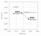
- the width of the magnetic wedge (length in the circumferential direction of the rotary electric machine) is 7.0 mm, and the thickness (length in the radial direction of the rotary electric machine) is changed to 0.0 mm (without magnetic wedge), 1.5 mm, and 3.0 mm. Calculated.
- FIG. 13 shows the electromagnetic field simulation results.
- the calculation results are plotted with the efficiency of the rotary electric machine on the horizontal axis and the torque of the rotary electric machine on the vertical axis.
- the torque on the vertical axis shows the value standardized by the torque value when there is no magnetic wedge.
- the space of the coil 33 increases as the magnetic wedge 100 becomes thinner, so that the electrical resistance of the coil can be reduced by increasing the coil wire diameter, which further improves efficiency. Improvement can also be expected.
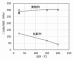
- the three-point bending strength at room temperature to 200 ° C. was measured using a universal testing machine (Type 5769 manufactured by Instron).
- the measurement conditions are a load cell capacity of 500 N, a fulcrum diameter of 4 mm, an indenter diameter of 10 mm, a distance between fulcrums of 16 mm, and a test speed of 0.5 mm / min.
- L is the distance between the fulcrums
- b the width of the sample
- h is the thickness of the sample.
- FIG. 14 shows the three-point bending strength of the example obtained as described above.
- the figure also shows the three-point bending strength of the comparative example.
- the three-point bending strength of the comparative example containing the resin decreases remarkably with increasing temperature, whereas the resin-less example of the present embodiment does not decrease in strength even at a high temperature of 200 ° C. and is at room temperature. Maintains the same high strength as.
- the magnetic wedge Since the internal temperature of the motor rises when the motor is driven, the magnetic wedge is required to have durability that does not deteriorate its characteristics even when exposed to a high temperature environment for a long time.
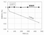
- the mass change (heat loss) due to aging was measured using the above-mentioned rod-shaped sample. Aging was carried out in air at 220 ° C. and 290 ° C., and the sample was taken out and cooled at regular time intervals, and the mass was measured at room temperature.
- the reason why the heating temperatures are set to 220 ° C. and 290 ° C. is as follows. 220 ° C. is the maximum temperature that the internal temperature of the motor can reach, and 290 ° C.
- the measurement result at 220 ° C. is shown in FIG. 15, and the measurement result at 290 ° C. is shown in FIG.
- the data of the example is the average value of 5 samples.
- the figure also shows the measurement results of the comparative example.
- the weight of Comparative Example decreased by 0.56% after 456 hours, whereas the weight change of Example remained less than 0.05%.
- the difference in weight change became remarkable, and after 240 hours, the weight loss of the comparative example was 10% or more, whereas the weight change of the example was still less than 0.05%. Further, when the three-point bending strength was measured after the above-mentioned 290 ° C.
- this embodiment is superior in durability to aging at high temperature for a long time as compared with the comparative example, and is a more practical material as a magnetic wedge.
- the example When the thermal conductivity was obtained by multiplying the thermal diffusivity, the specific heat, and the above-mentioned density, the example was 8.7 W / (m ⁇ K) and the comparative example was 1.5 W / (m ⁇ K). The example showed about 6 times higher thermal conductivity than the comparative example.
- the thermal conductivity of resin is as low as 1/10 or less of that of metal, so it is considered that the high thermal conductivity of this example is due to the feature of resin-less.
- Such a cooling effect is preferably as high as the thermal conductivity of the magnetic wedge, for example, the thermal conductivity is preferably 2.0 W / (m ⁇ K) or more, more preferably 5.0 W / (m ⁇ K) or more, 8 More preferably, it is 0.0 W / (m ⁇ K) or more.
- the thermal conductivity of the electromagnetic steel sheet constituting the stator of the rotary electric machine is generally as high as about 20 W / (m ⁇ K), it can be expected that the closer the thermal conductivity of the magnetic wedge is to this value, the higher the cooling effect. .. Therefore, the thermal conductivity of the magnetic wedge is preferably 1/10 or more, more preferably 1/5 or more, and further preferably 1/3 or more of the magnetic material (electromagnetic steel plate) constituting the stator. preferable.
- the particles constituting the magnetic wedge are bound by the surface oxide phase, it is possible to provide a magnetic wedge having high electric resistance and bending strength. Further, by adding voids to these configurations, it is possible to provide a magnetic wedge having high electric resistance and bending strength and having a adjusted relative magnetic permeability. Further, since the magnetic wedge of the present invention is made of no resin, it can be a magnetic wedge having excellent heat resistance, heat dissipation and long-term reliability.
- Fe-based soft magnetic particles 2 Void 3: Surface oxide phase 4: Non-magnetic particles 5: Surface oxide phase 6: Void 31: Stator 32: Rotor 33: Coil 34: Teeth 100, 200: Magnetic wedge 300: Rotating electric machine
Landscapes
- Engineering & Computer Science (AREA)
- Chemical & Material Sciences (AREA)
- Power Engineering (AREA)
- Mechanical Engineering (AREA)
- Manufacturing & Machinery (AREA)
- Materials Engineering (AREA)
- Metallurgy (AREA)
- Organic Chemistry (AREA)
- Dispersion Chemistry (AREA)
- Physics & Mathematics (AREA)
- Electromagnetism (AREA)
- Spectroscopy & Molecular Physics (AREA)
- Soft Magnetic Materials (AREA)
- Insulation, Fastening Of Motor, Generator Windings (AREA)
- Powder Metallurgy (AREA)
- Manufacture Of Motors, Generators (AREA)
- Manufacture Of Metal Powder And Suspensions Thereof (AREA)
Priority Applications (5)
| Application Number | Priority Date | Filing Date | Title |
|---|---|---|---|
| EP20854793.5A EP4020767A4 (en) | 2019-08-20 | 2020-08-06 | Magnetic wedge, rotating electrical machine, and method for manufacturing magnetic wedge |
| US17/636,032 US20220294279A1 (en) | 2019-08-20 | 2020-08-06 | Magnetic wedge, rotary electric machine, and method for manufacturing magnetic wedge |
| CN202080058044.3A CN114270456A (zh) | 2019-08-20 | 2020-08-06 | 磁性楔、旋转电机、及磁性楔的制造方法 |
| KR1020227004975A KR102582964B1 (ko) | 2019-08-20 | 2020-08-06 | 자성 쐐기, 회전 전기 및 자성 쐐기의 제조 방법 |
| JP2020570205A JP6880472B1 (ja) | 2019-08-20 | 2020-08-06 | 磁性楔、回転電機、および磁性楔の製造方法 |
Applications Claiming Priority (4)
| Application Number | Priority Date | Filing Date | Title |
|---|---|---|---|
| JP2019-150117 | 2019-08-20 | ||
| JP2019150117 | 2019-08-20 | ||
| JP2020023466 | 2020-02-14 | ||
| JP2020-023466 | 2020-02-14 |
Publications (1)
| Publication Number | Publication Date |
|---|---|
| WO2021033567A1 true WO2021033567A1 (ja) | 2021-02-25 |
Family
ID=74660927
Family Applications (1)
| Application Number | Title | Priority Date | Filing Date |
|---|---|---|---|
| PCT/JP2020/030213 Ceased WO2021033567A1 (ja) | 2019-08-20 | 2020-08-06 | 磁性楔、回転電機、および磁性楔の製造方法 |
Country Status (6)
| Country | Link |
|---|---|
| US (1) | US20220294279A1 (https=) |
| EP (1) | EP4020767A4 (https=) |
| JP (2) | JP6880472B1 (https=) |
| KR (1) | KR102582964B1 (https=) |
| CN (1) | CN114270456A (https=) |
| WO (1) | WO2021033567A1 (https=) |
Cited By (3)
| Publication number | Priority date | Publication date | Assignee | Title |
|---|---|---|---|---|
| WO2022210895A1 (ja) * | 2021-03-31 | 2022-10-06 | 日本製鉄株式会社 | 回転電機、ステータの鉄心及びロータの鉄心のセット、回転電機の製造方法、ステータ用無方向性電磁鋼板及びロータ用無方向性電磁鋼板の製造方法、ステータ及びロータの製造方法、及び、無方向性電磁鋼板のセット |
| RU2826073C2 (ru) * | 2021-03-31 | 2024-09-03 | Ниппон Стил Корпорейшн | Вращающаяся электрическая машина, набор сердечника статора и сердечника ротора, способ изготовления вращающейся электрической машины, способ изготовления листа изотропной электротехнической стали для статора и листа изотропной электротехнической стали для ротора, способ изготовления статора и ротора и набор листов изотропной электротехнической стали |
| JP2025047639A (ja) * | 2023-09-21 | 2025-04-03 | 株式会社東芝 | 磁性楔及び回転電機 |
Families Citing this family (4)
| Publication number | Priority date | Publication date | Assignee | Title |
|---|---|---|---|---|
| US11081920B2 (en) * | 2017-09-29 | 2021-08-03 | Hamilton Sundstrand Corporation | Rotor wedges and layers and heat sinks |
| EP4415225A4 (en) * | 2021-10-08 | 2025-01-15 | Proterial, Ltd. | MAGNETIC WEDGE, DYNAMOELECTRIC MACHINE AND METHOD FOR MANUFACTURING THE MAGNETIC WEDGE |
| US12087483B2 (en) * | 2022-02-14 | 2024-09-10 | General Electric Company | Dual phase soft magnetic particle combinations, components and manufacturing methods |
| WO2025224955A1 (ja) * | 2024-04-25 | 2025-10-30 | 日産自動車株式会社 | 電動機 |
Citations (4)
| Publication number | Priority date | Publication date | Assignee | Title |
|---|---|---|---|---|
| JPS5450807A (en) * | 1977-09-12 | 1979-04-21 | Siemens Ag | Synchronous motor |
| JPS6277030A (ja) | 1985-09-27 | 1987-04-09 | Hitachi Ltd | 回転電機の磁性楔 |
| JPH11238614A (ja) * | 1998-02-20 | 1999-08-31 | Yaskawa Electric Corp | 軟質磁性材料とその製造法およびそれを用いた電気機器 |
| WO2018008738A1 (ja) | 2016-07-08 | 2018-01-11 | 株式会社日立産機システム | 回転電機及び回転電機の製造方法 |
Family Cites Families (13)
| Publication number | Priority date | Publication date | Assignee | Title |
|---|---|---|---|---|
| CN1065756A (zh) * | 1991-04-11 | 1992-10-28 | 上海达美医用塑料厂 | 电机槽楔磁性材料及其制备和使用方法 |
| JPH07123622A (ja) * | 1993-10-29 | 1995-05-12 | Toshiba Corp | 永久磁石式回転電機 |
| JPH08172742A (ja) * | 1994-12-19 | 1996-07-02 | Toshiba Corp | 永久磁石界磁方式回転電機 |
| JP2002249802A (ja) | 2001-02-26 | 2002-09-06 | Alps Electric Co Ltd | 非晶質軟磁性合金圧密体及びそれを用いた圧粉磁心 |
| JP4866971B2 (ja) * | 2010-04-30 | 2012-02-01 | 太陽誘電株式会社 | コイル型電子部品およびその製造方法 |
| ITMI20110539A1 (it) * | 2011-03-31 | 2012-10-01 | Ansaldo Sistemi Spa | Bietta magnetica per cave di un macchina elettrica rotante. |
| JP4906972B1 (ja) * | 2011-04-27 | 2012-03-28 | 太陽誘電株式会社 | 磁性材料およびそれを用いたコイル部品 |
| EP2947670B8 (en) * | 2013-01-16 | 2019-06-05 | Hitachi Metals, Ltd. | Method for manufacturing powder magnetic core, powder magnetic core, and coil component |
| EP2854260A1 (de) * | 2013-09-27 | 2015-04-01 | Siemens Aktiengesellschaft | Nutverschlussmasse, Nutverschluss und Verfahren zum Herstellen eines Nutverschlusses |
| CN103701266A (zh) * | 2013-12-11 | 2014-04-02 | 安徽威能电机有限公司 | 定向引拔磁性槽楔的制造方法 |
| JP6345146B2 (ja) * | 2015-03-31 | 2018-06-20 | 太陽誘電株式会社 | コイル部品 |
| JP2017135358A (ja) | 2016-01-22 | 2017-08-03 | 株式会社東芝 | 扁平磁性金属粒子、圧粉材料、回転電機、モータ、発電機 |
| JP6829173B2 (ja) * | 2017-09-21 | 2021-02-10 | 株式会社東芝 | 磁性楔及び回転電機 |
-
2020
- 2020-08-06 EP EP20854793.5A patent/EP4020767A4/en active Pending
- 2020-08-06 WO PCT/JP2020/030213 patent/WO2021033567A1/ja not_active Ceased
- 2020-08-06 JP JP2020570205A patent/JP6880472B1/ja active Active
- 2020-08-06 CN CN202080058044.3A patent/CN114270456A/zh active Pending
- 2020-08-06 US US17/636,032 patent/US20220294279A1/en active Pending
- 2020-08-06 KR KR1020227004975A patent/KR102582964B1/ko active Active
-
2021
- 2021-04-20 JP JP2021071401A patent/JP7805085B2/ja active Active
Patent Citations (4)
| Publication number | Priority date | Publication date | Assignee | Title |
|---|---|---|---|---|
| JPS5450807A (en) * | 1977-09-12 | 1979-04-21 | Siemens Ag | Synchronous motor |
| JPS6277030A (ja) | 1985-09-27 | 1987-04-09 | Hitachi Ltd | 回転電機の磁性楔 |
| JPH11238614A (ja) * | 1998-02-20 | 1999-08-31 | Yaskawa Electric Corp | 軟質磁性材料とその製造法およびそれを用いた電気機器 |
| WO2018008738A1 (ja) | 2016-07-08 | 2018-01-11 | 株式会社日立産機システム | 回転電機及び回転電機の製造方法 |
Non-Patent Citations (1)
| Title |
|---|
| See also references of EP4020767A4 |
Cited By (9)
| Publication number | Priority date | Publication date | Assignee | Title |
|---|---|---|---|---|
| WO2022210895A1 (ja) * | 2021-03-31 | 2022-10-06 | 日本製鉄株式会社 | 回転電機、ステータの鉄心及びロータの鉄心のセット、回転電機の製造方法、ステータ用無方向性電磁鋼板及びロータ用無方向性電磁鋼板の製造方法、ステータ及びロータの製造方法、及び、無方向性電磁鋼板のセット |
| JPWO2022210895A1 (https=) * | 2021-03-31 | 2022-10-06 | ||
| TWI813234B (zh) * | 2021-03-31 | 2023-08-21 | 日商日本製鐵股份有限公司 | 旋轉電機、定子鐵心及轉子鐵心的組合、旋轉電機的製造方法、定子用無方向性電磁鋼板及轉子用無方向性電磁鋼板的製造方法、定子及轉子的製造方法、以及無方向性電磁鋼板的組合 |
| KR20230123512A (ko) * | 2021-03-31 | 2023-08-23 | 닛폰세이테츠 가부시키가이샤 | 회전 전기 기기, 스테이터의 철심 및 로터의 철심의세트, 회전 전기 기기의 제조 방법, 스테이터용 무방향성 전자 강판 및 로터용 무방향성 전자 강판의 제조 방법, 스테이터 및 로터의 제조 방법, 그리고 무방향성 전자 강판의 세트 |
| JP7527378B2 (ja) | 2021-03-31 | 2024-08-02 | 日本製鉄株式会社 | 回転電機、ステータの鉄心及びロータの鉄心のセット、ステータ用無方向性電磁鋼板及びロータ用無方向性電磁鋼板の製造方法、ステータ及びロータの製造方法、及び、無方向性電磁鋼板のセット |
| RU2826073C2 (ru) * | 2021-03-31 | 2024-09-03 | Ниппон Стил Корпорейшн | Вращающаяся электрическая машина, набор сердечника статора и сердечника ротора, способ изготовления вращающейся электрической машины, способ изготовления листа изотропной электротехнической стали для статора и листа изотропной электротехнической стали для ротора, способ изготовления статора и ротора и набор листов изотропной электротехнической стали |
| KR102810261B1 (ko) * | 2021-03-31 | 2025-05-21 | 닛폰세이테츠 가부시키가이샤 | 회전 전기 기기, 스테이터의 철심 및 로터의 철심의 세트, 회전 전기 기기의 제조 방법, 스테이터용 무방향성 전자 강판 및 로터용 무방향성 전자 강판의 제조 방법, 스테이터 및 로터의 제조 방법, 그리고 무방향성 전자 강판의 세트 |
| US12451737B2 (en) | 2021-03-31 | 2025-10-21 | Nippon Steel Corporation | Rotating electrical machine, stator core and rotor core set, method for manufacturing rotating electrical machine, method for manufacturing non-oriented electrical steel sheet for stator and non-oriented electrical steel sheet for rotor, method for manufacturing stator and rotor, and non-oriented electrical steel sheet set |
| JP2025047639A (ja) * | 2023-09-21 | 2025-04-03 | 株式会社東芝 | 磁性楔及び回転電機 |
Also Published As
| Publication number | Publication date |
|---|---|
| JP2021143424A (ja) | 2021-09-24 |
| EP4020767A4 (en) | 2023-11-22 |
| EP4020767A1 (en) | 2022-06-29 |
| JP7805085B2 (ja) | 2026-01-23 |
| JPWO2021033567A1 (ja) | 2021-09-13 |
| CN114270456A (zh) | 2022-04-01 |
| JP6880472B1 (ja) | 2021-06-02 |
| KR102582964B1 (ko) | 2023-09-26 |
| KR20220034870A (ko) | 2022-03-18 |
| US20220294279A1 (en) | 2022-09-15 |
Similar Documents
| Publication | Publication Date | Title |
|---|---|---|
| JP6880472B1 (ja) | 磁性楔、回転電機、および磁性楔の製造方法 | |
| JP6365670B2 (ja) | 磁心、磁心の製造方法およびコイル部品 | |
| CN104756203B (zh) | 复合磁性体及其制造方法 | |
| JP6071211B2 (ja) | 低磁歪高磁束密度複合軟磁性材とその製造方法 | |
| JP7255719B2 (ja) | 磁性楔の製造方法、磁性楔、回転電機用固定子及び回転電機 | |
| WO2010073590A1 (ja) | 複合軟磁性材料とその製造方法 | |
| JPWO2010103709A1 (ja) | 圧粉磁芯およびそれを用いた磁性素子 | |
| KR100844613B1 (ko) | 입자 표면이 내산화성 금속으로 피복된 자기 분말을포함하는 본드 자석으로 이루어진 자기 코어 및 그 자기코어를 포함하는 인덕턴스 부품 | |
| JP2013520029A (ja) | 増大された電気抵抗を有する希土類成層複合磁石 | |
| JP2009185312A (ja) | 複合軟磁性材料、それを用いた圧粉磁心、およびそれらの製造方法 | |
| JP2014207288A (ja) | 磁心用軟磁性材料、圧粉磁心およびコイル部材 | |
| JP2013008762A (ja) | 複合磁性材料 | |
| JP7016713B2 (ja) | 圧粉磁心および磁心用粉末 | |
| JP7613148B2 (ja) | 磁性楔および回転電機 | |
| JP2010238930A (ja) | 複合軟磁性材料、複合軟磁性材料の製造方法及び電磁気回路部品 | |
| JP2010185126A (ja) | 複合軟磁性材料とその製造方法 | |
| JP4750471B2 (ja) | 低磁歪体及びこれを用いた圧粉磁芯 | |
| US20250175051A1 (en) | Method for manufacturing magnetic wedge, magnetic wedge, stator for rotating electric machine, and rotating electric machine | |
| CN104439234B (zh) | 一种稀土元素掺杂的镍硅铝软磁材料的制备方法 | |
| JP4784173B2 (ja) | 希土類磁石及びその製造方法 | |
| CN119811865B (zh) | 一种一体成型电感磁芯结构 | |
| JP2018137349A (ja) | 磁心およびコイル部品 | |
| JP2010010501A (ja) | 配向圧粉磁心 | |
| JP2008143720A (ja) | マグネタイト−鉄複合粉末およびその製造方法ならびに圧粉磁芯 | |
| JPH1083910A (ja) | 磁心とこれに用いる粉末 |
Legal Events
| Date | Code | Title | Description |
|---|---|---|---|
| ENP | Entry into the national phase |
Ref document number: 2020570205 Country of ref document: JP Kind code of ref document: A |
|
| 121 | Ep: the epo has been informed by wipo that ep was designated in this application |
Ref document number: 20854793 Country of ref document: EP Kind code of ref document: A1 |
|
| ENP | Entry into the national phase |
Ref document number: 20227004975 Country of ref document: KR Kind code of ref document: A |
|
| NENP | Non-entry into the national phase |
Ref country code: DE |
|
| ENP | Entry into the national phase |
Ref document number: 2020854793 Country of ref document: EP Effective date: 20220321 |