WO2021029366A1 - 軸継手の特性評価装置及び特性評価方法 - Google Patents
軸継手の特性評価装置及び特性評価方法 Download PDFInfo
- Publication number
- WO2021029366A1 WO2021029366A1 PCT/JP2020/030395 JP2020030395W WO2021029366A1 WO 2021029366 A1 WO2021029366 A1 WO 2021029366A1 JP 2020030395 W JP2020030395 W JP 2020030395W WO 2021029366 A1 WO2021029366 A1 WO 2021029366A1
- Authority
- WO
- WIPO (PCT)
- Prior art keywords
- shaft joint
- shaft
- amplitude
- torque
- resonance frequency
- Prior art date
- Legal status (The legal status is an assumption and is not a legal conclusion. Google has not performed a legal analysis and makes no representation as to the accuracy of the status listed.)
- Ceased
Links
Images





Classifications
-
- H—ELECTRICITY
- H02—GENERATION; CONVERSION OR DISTRIBUTION OF ELECTRIC POWER
- H02P—CONTROL OR REGULATION OF ELECTRIC MOTORS, ELECTRIC GENERATORS OR DYNAMO-ELECTRIC CONVERTERS; CONTROLLING TRANSFORMERS, REACTORS OR CHOKE COILS
- H02P23/00—Arrangements or methods for the control of AC motors characterised by a control method other than vector control
- H02P23/30—Direct torque control [DTC] or field acceleration method [FAM]
-
- G—PHYSICS
- G01—MEASURING; TESTING
- G01M—TESTING STATIC OR DYNAMIC BALANCE OF MACHINES OR STRUCTURES; TESTING OF STRUCTURES OR APPARATUS, NOT OTHERWISE PROVIDED FOR
- G01M13/00—Testing of machine parts
- G01M13/02—Gearings; Transmission mechanisms
- G01M13/022—Power-transmitting couplings or clutches
-
- G—PHYSICS
- G01—MEASURING; TESTING
- G01H—MEASUREMENT OF MECHANICAL VIBRATIONS OR ULTRASONIC, SONIC OR INFRASONIC WAVES
- G01H1/00—Measuring characteristics of vibrations in solids by using direct conduction to the detector
- G01H1/003—Measuring characteristics of vibrations in solids by using direct conduction to the detector of rotating machines
-
- G—PHYSICS
- G01—MEASURING; TESTING
- G01H—MEASUREMENT OF MECHANICAL VIBRATIONS OR ULTRASONIC, SONIC OR INFRASONIC WAVES
- G01H1/00—Measuring characteristics of vibrations in solids by using direct conduction to the detector
- G01H1/10—Measuring characteristics of vibrations in solids by using direct conduction to the detector of torsional vibrations
-
- G—PHYSICS
- G01—MEASURING; TESTING
- G01H—MEASUREMENT OF MECHANICAL VIBRATIONS OR ULTRASONIC, SONIC OR INFRASONIC WAVES
- G01H1/00—Measuring characteristics of vibrations in solids by using direct conduction to the detector
- G01H1/12—Measuring characteristics of vibrations in solids by using direct conduction to the detector of longitudinal or not specified vibrations
- G01H1/14—Frequency
-
- G—PHYSICS
- G01—MEASURING; TESTING
- G01H—MEASUREMENT OF MECHANICAL VIBRATIONS OR ULTRASONIC, SONIC OR INFRASONIC WAVES
- G01H1/00—Measuring characteristics of vibrations in solids by using direct conduction to the detector
- G01H1/12—Measuring characteristics of vibrations in solids by using direct conduction to the detector of longitudinal or not specified vibrations
- G01H1/16—Amplitude
-
- G—PHYSICS
- G01—MEASURING; TESTING
- G01M—TESTING STATIC OR DYNAMIC BALANCE OF MACHINES OR STRUCTURES; TESTING OF STRUCTURES OR APPARATUS, NOT OTHERWISE PROVIDED FOR
- G01M13/00—Testing of machine parts
- G01M13/02—Gearings; Transmission mechanisms
- G01M13/025—Test-benches with rotational drive means and loading means; Load or drive simulation
-
- G—PHYSICS
- G01—MEASURING; TESTING
- G01M—TESTING STATIC OR DYNAMIC BALANCE OF MACHINES OR STRUCTURES; TESTING OF STRUCTURES OR APPARATUS, NOT OTHERWISE PROVIDED FOR
- G01M13/00—Testing of machine parts
- G01M13/02—Gearings; Transmission mechanisms
- G01M13/028—Acoustic or vibration analysis
-
- H—ELECTRICITY
- H02—GENERATION; CONVERSION OR DISTRIBUTION OF ELECTRIC POWER
- H02P—CONTROL OR REGULATION OF ELECTRIC MOTORS, ELECTRIC GENERATORS OR DYNAMO-ELECTRIC CONVERTERS; CONTROLLING TRANSFORMERS, REACTORS OR CHOKE COILS
- H02P23/00—Arrangements or methods for the control of AC motors characterised by a control method other than vector control
- H02P23/18—Controlling the angular speed together with angular position or phase
- H02P23/186—Controlling the angular speed together with angular position or phase of one shaft by controlling the prime mover
Definitions
- the present invention relates to a characteristic evaluation device and a characteristic evaluation method for evaluating the characteristics of a machine element, and more particularly to a characteristic evaluation device and a characteristic evaluation method for a shaft joint connecting two shafts.
- a physical parameter identification method that characterizes a feed mechanism in a positioning device that positions a transport object, including a feed drive mechanism (linear motion mechanism) that moves the transported object in the linear motion direction by converting rotational motion into linear motion. It is known (for example, Patent Document 1).
- the frequency characteristic of the positioning device is measured by using a frequency characteristic analyzer and a servo analyzer, and the resonance value and the resonance frequency are acquired from the measurement result. Then, based on the acquired resonance value and resonance frequency, the intrinsic angular frequency, damping coefficient, spring constant, and viscous friction resistance of the feed mechanism are calculated (for example, Patent Document 1).
- Non-Patent Document 1 Non-Patent Document 1
- the inventors have stated that the accuracy of the identified physical parameters may decrease depending on the response characteristics of the motor system after issuing a torque command to generate the drive torque in the motor until the drive torque is generated. I found it.
- the present invention has been devised in view of the problems of the prior art, and is capable of appropriately evaluating the characteristics of the shaft joint in consideration of the response characteristics of the motor system.
- the main purpose is to provide a characteristic evaluation device and a characteristic evaluation method.
- a characteristic evaluation device (1, 101) that evaluates the characteristics of the shaft joint (4) connecting both shafts in order to transmit torque from the drive shaft (2) to the driven shaft (3).
- a drive motor (11) that applies drive torque to the drive shaft
- a rotation angle sensor (14) that acquires the rotation angle of the drive shaft, and a given torque command ( Tref ).
- a motor system (5) including a motor control unit (13) that controls the drive motor and a rotational load unit (18) connected to the driven shaft in order to output torque in response to the torque command.
- the torque command is output to the motor control unit so as to output the predetermined drive torque, and the torque amplitude corresponding to the torque command is obtained based on the rotation angle detected by the rotation angle sensor.
- It has a processor (21) capable of calculating the frequency characteristic of the gain of the amplitude of the angular velocity ( ⁇ ) of the rotation angle, and the processor has a response characteristic of the motor system and a state in which the shaft joint connects the two shafts.
- the characteristic of the shaft joint is calculated based on the frequency characteristic calculated in 1.
- the characteristics of the shaft joint can be evaluated more appropriately.
- the processor has a transfer function (G) as a response characteristic of the motor system until the drive motor is driven by the torque command and a corresponding torque is generated from the drive motor.
- * (S)) is used to acquire the frequency characteristics with the shaft joint connected, and the resonance frequency (f 0 ) of the shaft joint and the gain at the resonance frequency are acquired from the frequency characteristics.
- the torsional rigidity (K c ) of the shaft joint is calculated using the resonance frequency
- the viscosity coefficient ( cc ) of the shaft joint is calculated using the transfer function, the torsional rigidity, and the gain at the resonance frequency. Is characterized by calculating.
- the torsional rigidity of the shaft joint can be easily calculated using the frequency characteristics. Further, the viscosity coefficient of the shaft joint can be calculated in consideration of the transfer function from the time when the torque command is given to the motor to the time when the torque is generated on the drive shaft. As a result, the viscosity coefficient is calculated in consideration of the response characteristics of the motor system, so that the accuracy of the calculated viscosity coefficient is improved.
- the processor uses the transfer function to convert the gain at the resonance frequency into a conversion value corresponding to the gain at the resonance frequency when the transfer function is 1. It is characterized in that the viscosity coefficient of the shaft joint is calculated by using the torsional rigidity and the converted value.
- the processor acquires the response characteristics of the motor system by the frequency characteristics when the drive motor is driven in a state where the shaft joints are not connected to both shafts. It is characterized by doing.
- a fifth aspect of the present invention is a method for evaluating the characteristics of a shaft joint that evaluates the characteristics of the shaft joint (4) connecting both shafts in order to transmit torque from the drive shaft (2) to the driven shaft (3).
- the rotation angle sensor (14) Based on the drive motor (11) that applies drive torque to the drive shaft, the rotation angle sensor (14) that acquires the rotation angle of the drive shaft, and the given torque command ( Tref ).
- a motor system (5) including a motor control unit (13) that controls the drive motor, a rotational load unit (18) connected to the driven shaft, and a predetermined value so as to output torque in response to the torque command.
- the torque command is output to the motor control unit so as to output the drive torque, and the rotation angle with respect to the torque amplitude corresponding to the torque command is based on the rotation angle detected by the rotation angle sensor.
- the step (ST5) of acquiring the frequency characteristic in a state where the shaft joint connects both shafts was acquired. It is characterized in that the steps (ST7, ST10) of calculating the characteristics of the shaft joint based on the frequency characteristics and the response characteristics of the motor system are executed.
- the characteristics of the shaft joint can be evaluated more appropriately.
- the step of acquiring the gain (ST6) the step of calculating the torsional rigidity (K c ) of the shaft joint using the resonance frequency (ST7), and the torque command as the response characteristic of the motor system.
- the viscosity coefficient ( cc ) of the shaft joint is calculated using the transmission function until the drive motor is driven and the corresponding torque is generated from the drive motor, the torsional rigidity, and the gain at the resonance frequency. It is characterized by including the steps (ST9, ST10) to be performed.
- the torsional rigidity of the shaft joint can be easily calculated using the frequency characteristics. Further, the viscosity coefficient of the shaft joint can be calculated in consideration of the transfer function from the time when the torque command is given to the motor to the time when the torque is generated on the drive shaft. As a result, the viscosity coefficient is calculated in consideration of the response characteristics of the motor system, so that the accuracy of the calculated viscosity coefficient is improved.
- the transfer function (G * (s)) is used to obtain the gain at the resonance frequency, and the transfer function is 1.
- An eighth aspect of the present invention includes a step of acquiring the response characteristics of the motor system based on the frequency characteristics when the drive motor is driven in a state where the shaft joints are not connected to both shafts. It is good.
- a ninth aspect of the present invention is the shaft joint characteristic evaluation device (101), wherein the processor outputs the drive torque having two or more amplitudes in a state where the shaft joint connects the two shafts.
- the torque command is output to the motor control unit, the frequency characteristics corresponding to the respective amplitudes are calculated, and the amplitude is based on the response characteristics of the motor system and the calculated frequency characteristics.
- the characteristics of the shaft joint corresponding to each of the above are calculated, the amplitude of the torque command, the amplitude of the drive torque at the resonance frequency of the shaft joint, the amplitude of the rotation angle at the resonance frequency, and the angular velocity at the resonance frequency. It is preferable to output the relationship between at least one of the amplitudes of the above and the characteristics of the shaft joint.
- the amplitude dependence of the drive torque applied to the shaft joint of the characteristics of the shaft joint is output.
- the user can appropriately evaluate the input-dependent characteristics of the shaft joint, so that it is possible to predict the vibration characteristics under various operating conditions and design an appropriate control system.
- the processor obtains the torsional rigidity of the shaft joint for each of the acquired frequency characteristics, the amplitude of the torque command, the amplitude of the drive torque at the resonance frequency, and the said. It is preferable to output the relationship between at least one of the amplitude of the rotation angle at the resonance frequency, the amplitude of the angular velocity at the resonance frequency, and the torsional rigidity of the shaft joint.
- the amplitude dependence of the drive torque of the torsional rigidity of the shaft joint is output.
- the input dependence of the shaft joint can be appropriately evaluated.
- the amplitude dependence of the torsional rigidity is output, the content is easily understood by the user, and the convenience of the shaft joint characteristic evaluation device is enhanced.
- the processor outputs the torque command to the motor control unit so as to output the drive torque having two or more amplitudes, and the frequency characteristic corresponding to each amplitude.
- the viscosity coefficient of the shaft joint was obtained for each of the acquired frequency characteristics, and the amplitude of the torque command, the amplitude of the driving torque at the resonance frequency, and the amplitude of the rotation angle at the resonance frequency were obtained. It is preferable to output the relationship between at least one of the amplitudes of the angular velocity at the resonance frequency and the viscosity coefficient of the shaft joint.
- the amplitude dependence of the drive torque of the viscosity coefficient of the shaft joint is output.
- the input-dependent characteristics of the shaft joint can be appropriately evaluated.
- the amplitude dependence of the viscosity coefficient is output, the content is easily understood by the user, and the convenience of the shaft joint characteristic evaluation device is enhanced.
- a twelfth aspect of the present invention is a method for evaluating a shaft joint, in which the drive torque having two or more amplitudes is output to the motor system in a state where the shaft joint connects the two shafts, respectively. Based on the step of acquiring the frequency characteristic corresponding to the amplitude of the above, the acquired frequency characteristic, and the response characteristic of the motor system, the step of calculating the characteristic of the shaft joint corresponding to the respective amplitude. And should be executed.
- a step of acquiring the frequency characteristics having two or more amplitudes in a state where the shaft joints are connected, and the resonance frequency of the shaft joints and the resonance from the respective frequency characteristics The step of acquiring the gain at the frequency, the step of calculating the torsional rigidity of the shaft joint corresponding to each of the amplitudes using the resonance frequency, the amplitude of the torque command, and the driving torque at the resonance frequency. It is preferable to include at least one of the amplitude of, the amplitude of the rotation angle at the resonance frequency, the amplitude of the angular velocity at the resonance frequency, and a step of outputting the relationship between the torsional rigidity of the shaft joint.
- the amplitude dependence of the drive torque of the torsional rigidity of the shaft joint can be evaluated. This makes it possible to predict vibration characteristics under various operating conditions and design an appropriate control system, which makes it easier for the user to understand the contents.
- the amplitude dependence of the drive torque of the viscosity coefficient of the shaft joint can be evaluated. This makes it possible to predict vibration characteristics under various operating conditions and design an appropriate control system, which makes it easier for the user to understand the contents.
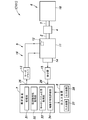
- the evaluation device 1 is a device for evaluating the characteristics of a shaft joint 4 (coupling) that connects both shafts in order to transmit the torque of the drive shaft 2 that is rotationally driven to the driven shaft 3. More specifically, the characteristic evaluation device 1 according to the present invention quantifies the torsional rigidity K c [Nm / rad] and the viscosity coefficient c c [Nm / (rad / s)], which are the characteristics of the shaft joint 4. Can be evaluated.
- the characteristic evaluation device 1 includes a motor system 5 having a drive shaft 2, a driven device 6 having a driven shaft 3, an analysis device 7, and an input / output device 8.
- the shaft joint 4 to be evaluated is arranged so as to connect the drive shaft 2 and the driven shaft 3.
- the motor system 5 includes a drive motor 11, a current sensor 12, a servo driver 13 (motor control unit), a rotation angle sensor 14, and a differentiator 15.
- the drive motor 11 is a general-purpose servomotor, and the output shafts to be the drive shafts 2 are arranged so as to be substantially horizontal, and a drive torque T m is applied to the drive shafts 2.
- the current sensor 12 is a sensor that measures the current value of the current (hereinafter referred to as the drive current) flowing through the drive motor 11.
- the servo driver 13 supplies a drive current to the drive motor 11, and causes the drive motor 11 to output a torque (hereinafter, command torque value) corresponding to the torque command Tref input from the analyzer 7.
- the drive motor 11 is controlled by controlling the current value. More specifically, the servo driver 13 feeds back the drive current so that the deviation between the current value acquired by the current sensor 12 and the current value corresponding to the command torque value becomes zero.
- the servo driver 13, the current sensor 12, and the drive motor 11 form a current loop (feedback loop), and the servo driver 13, the current sensor 12, and the drive motor 11 cooperate to control the torque.
- it functions as a servo system 16 (servo mechanism) that automatically drives the drive shaft 2 to output a drive torque T m corresponding to the control amount.
- the rotation angle sensor 14 is a so-called rotary encoder for measuring the rotation angle of the drive shaft 2, and may include any detection element of optical type, magnetic type, and capacitance type.
- the differentiator 15 is connected to the rotation angle sensor 14 and the analysis device 7.
- the differentiator 15 acquires the rotation angle of the drive shaft 2 from the rotation angle sensor 14, time-differentiates the rotation angle to calculate the angular velocity ⁇ , and outputs the angular velocity ⁇ to the analyzer 7.
- the driven device 6 includes a rotating load unit 18 which is connected to the driven shaft 3 and applies a load to the rotational movement of the driven shaft 3.
- the rotational load unit 18 may be composed of a disk or the like having a predetermined moment of inertia. Further, the rotary load unit 18 may be composed of motors having substantially the same shape as or different in size from the drive motor 11. At this time, the output shaft of the motor may be fixed to the driven shaft 3.
- the driven device 6 itself may be configured by a motor having substantially the same shape as or different in size from the driving motor 11. When the motor is used as the driven device 6, the output shaft may be used as the driven shaft 3.
- the motor When the motor is used as the rotary load unit 18 or the motor is used as the driven device 6, the motor is added to the driven shaft 3 by giving commands such as torque, the rotation angle of the driven shaft 3, or the angular velocity of the driven shaft 3.
- the load can be changed.
- the characteristic test of the shaft joint 4 in which the load state is changed can be performed.
- the analyzer 7 outputs a torque command Tref to the servo driver 13 and is based on the rotation angle of the drive shaft 2, more specifically, the angular velocity ⁇ which is the time derivative of the rotation angle calculated by the differentiator 15.
- This is a device that calculates the characteristics of the joint 4.
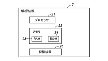
- the analysis device 7 is composed of a computer equipped with known hardware, has one or more processors 21 that execute processing based on a predetermined program, and a memory 22 that holds data and the like necessary for the processing.
- the memory 22 includes a RAM 23 (Random Access Memory) that functions as a work area of the processor 21 and a ROM 24 (Read Only Memory) that stores programs and data executed by the processor 21.
- the analysis device 7 further includes a storage device 25 such as an HDD or SSD, and a plurality of input / output ports 26 (see FIG. 1) for connecting peripheral devices and the like.
- the input / output device 8 is a device for receiving input from the user and displaying the acquired characteristics of the shaft joint 4 to the user, and is connected to the analysis device 7 via the input / output port 26.
- the input / output device 8 includes an input device 27 such as a keyboard and a mouse used by the user for various settings in the analysis device 7, and an output device 28 including a liquid crystal monitor for displaying the analysis result.
- the input / output device 8 may be composed of a computer including a monitor and a keyboard.
- the servo driver 13 is also connected to the analysis device 7 via the input / output port 26. As a result, the analysis device 7 and the servo driver 13 can communicate with each other. For example, the analysis device 7 can output a torque command Tref to the servo driver 13 via the input / output port 26.
- the differentiator 15 is also connected to the analyzer 7 via the input / output port 26. As a result, the analysis device 7 can communicate with the differentiator 15, and for example, the analysis device 7 can acquire the angular velocity ⁇ of the drive shaft 2 from the differentiator 15.
- the analysis device 7 includes a storage unit 31, a frequency characteristic acquisition unit 32, a motor system response acquisition unit 33, and a shaft joint characteristic evaluation unit 34.
- the frequency characteristic acquisition unit 32, the motor system response acquisition unit 33, and the shaft joint characteristic evaluation unit 34 are each realized by executing an evaluation program for acquiring the characteristics of the shaft joint 4 by the processor 21.
- the storage unit 31 is realized by the memory 22, and appropriately stores information necessary for processing of the frequency characteristic acquisition unit 32, the motor system response acquisition unit 33, and the shaft joint characteristic evaluation unit 34. Furthermore, the storage unit 31 stores the moment of inertia J m of the rotor of the driving motor 11, the moment of inertia J l rotational loads 18. However, the moment of inertia of the rotor of the driving motor 11 J m and moment of inertia J l rotary load unit 18, the exact value is assumed to be known on the basis of their design specifications.
- the frequency characteristic acquisition unit 32 outputs a torque command Tref to the servo driver 13 so as to output a torque that vibrates with a predetermined amplitude while changing the frequency.
- the frequency characteristic acquisition unit 32 acquires the angular velocity ⁇ from the differentiator 15.
- the frequency characteristic acquisition unit 32 amplitude ratio of the angular velocity ⁇ with respect to the amplitude of the torque, i.e. the command torque value indicated by the torque command T ref (hereinafter, rate responsive parameter M) is calculated.
- the velocity response parameter M is converted into a gain (hereinafter, gain G) using the equation (1).
- the frequency characteristic acquisition unit 32 outputs the torque command T ref is varied within a predetermined range frequencies, shows the relationship between the gain of the angular velocity ⁇ of rotation angle with respect to the amplitude of the torque corresponding to the frequency and the torque command T ref Acquire frequency characteristics (see, for example, FIGS. 4 and 6).
- the torque command Tref output by the frequency characteristic acquisition unit 32 may be, for example, an M series signal that causes the drive motor 11 to output a torque whose amplitude changes randomly as a drive torque T m , or a pulse. It may be an impulse signal that outputs a torque whose amplitude changes in a similar manner as a drive torque T m .
- the frequency characteristic acquisition unit 32 acquires the time change of the gain, and then Fourier-converts the time change of the torque corresponding to the torque command Tref and the time change of the gain, and uses both of them to perform the relationship between the frequency and the gain. It is advisable to acquire the frequency characteristics indicating.
- the motor system response acquisition unit 33 acquires and acquires the frequency characteristics (see FIG. 4) by driving the drive motor 11 by the frequency characteristic acquisition unit 32 in a state where the shaft joint 4 is not connected.
- the response characteristics of the motor system 5 are identified from the frequency characteristics.
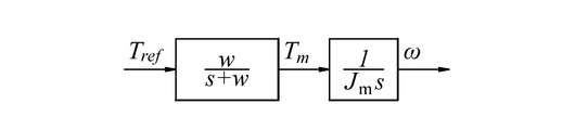
- the motor system response acquisition unit 33 has a block diagram (for example, a diagram) corresponding to the frequency characteristics acquired when the shaft joint 4 is not connected and the state where the shaft joint 4 is not connected.
- the response band w is identified so that it matches the frequency characteristics calculated based on 5).
- various known methods such as the least squares method and the search for a numerical solution are used. be able to.
- the response band w referred to here corresponds to the so-called cutoff frequency converted into the angular velocity ⁇ , and is one of the parameters related to the response characteristics of the motor.
- the response band w corresponds to a parameter when the response characteristic of the motor system 5 is expressed as the transfer function G * (s) of the first-order lag system.
- the motor becomes the torque command Tref at a frequency generally equal to or higher than the breaking frequency. It becomes difficult to follow, and the magnitude of the drive torque T m actually output to the drive shaft 2 becomes smaller than the torque that should be output to the drive shaft 2 by the torque command Tref .
- the response band w may be a parameter when the response characteristics of the motor system 5 are expressed as a high-order transfer function.
- the amplitude of the drive torque T m is almost equal to the amplitude of the torque command Tref , and in the frequency band larger than the cutoff frequency, the amplitude of the drive torque T m becomes the amplitude of the torque command Tref as the frequency increases. It is smaller than the amplitude.
- the amplitude of the drive torque T m is the torque command. It becomes smaller than the amplitude of the T ref, corresponding to the angular velocity ⁇ which they begin to deviate.
- the shaft joint characteristic evaluation unit 34 calculates the characteristics of the shaft joint 4 based on the response characteristics of the motor system 5 and the frequency characteristics acquired when the shaft joint 4 connects the drive shaft 2 and the driven shaft 3. ..
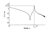
- the shaft joint characteristic evaluation unit 34 first obtains the peak gain G from the frequency characteristics acquired when the shaft joint 4 connects the drive shaft 2 and the driven shaft 3, as shown in FIG. to obtain the corresponding frequency, and the resonance frequency f 0. Further, the shaft joint characteristic evaluation unit 34 acquires the gain G at the resonance frequency f 0 from the frequency characteristics acquired when the shaft joint 4 connects the drive shaft 2 and the driven shaft 3, and gain exp at the resonance frequency f 0 . Let G f0 .
- the shaft joint characteristic evaluation unit 34 calculates the torsional rigidity K c by substituting the resonance frequency f 0 into the equation (2).
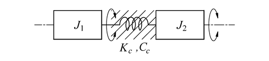
- J 1 and J 2 in the equation (2) are the moments of inertia [kgm 2 ] on the drive motor 11 side and the rotary load unit 18 side, respectively, and J 1 is the moment of inertia J m of the rotor of the drive motor 11.
- Half of the moment of inertia of the shaft joint 4 to be evaluated is the sum of J c / 2
- J 2 is the sum of the moment of inertia J l of the rotational load unit 18 and half the moment of inertia of the shaft joint 4 to be evaluated J c / 2. ..
- the moment of inertia J c of the shaft joint 4 to be evaluated is input by the user when the characteristics of the shaft joint 4 are evaluated.
- Equation (2) is an equation (2) showing a resonance frequency f 0 when the drive motor 11 and the rotational load portion 18 connected by the shaft joint 4 shown below are considered as a vibration model of the two inertial system shown in FIG. Corresponds to the solution of 3) for K c .
- the shaft joint characteristic evaluation unit 34 substitutes the gain exp G f0 at the resonance frequency f 0 obtained based on the frequency characteristics into the left side (G) of the equation (1) and converts it into the speed response parameter exp M f0 . To do.
- the shaft joint characteristic evaluation unit 34 sets the velocity response parameter exp M f0 at the resonance frequency f 0 by using the calculated torsional rigidity K c , the response band w, and the moments of inertia J 1 and J 2 as follows. Based on the equation (4), it is converted into the conversion speed response parameter M fo (conversion value).
- the converted speed response parameter M fo is the limit when the response band w at the resonance frequency f 0 is infinite (when the delay time is zero), that is, when the transfer function from the torque command T ref to the drive torque T m is 1. Corresponds to the speed response parameter.
- M FOW of formula (4) is at the resonant frequency f 0, for the amplitude of the torque command value, a torque that is expected to occur in the drive shaft 2 in the case of approximating the motor system 5 as a primary delay system It is a ratio of magnitudes of amplitude and is calculated by using the following equation (5).
- M FOW is not limited to Equation (4), or may be calculated by taking into account the motor system 5 as higher order systems.
- the shaft joint characteristic evaluation unit 34 uses the torsional rigidity K c , the converted speed response parameter M fo , and the moments of inertia J 1 and J 2 , and the viscosity coefficient c c based on the following equation (6). Is calculated.
- the velocity response parameter M f0 at the resonance frequency f 0 is expressed as the equation (8).
- the speed response parameter M f0 shown in the equation (8) is a speed response parameter at the resonance frequency f 0 of the transfer function G (s) from the drive torque T m generated by the drive motor 11 to the angular velocity ⁇ .
- the torque command Tref is output and the frequency characteristic is acquired by measuring the angular velocity ⁇ . Therefore, after the torque command Tref is output, the drive is used. It is necessary to consider the delay from the motor 11 until the drive torque T m is generated, that is, the delay of the motor system 5.
- the velocity response parameter M f0all when the motor system 5 is approximated as a first-order lag system can be expressed by the equation (9).
- the drive motor 11 is driven by a torque command T ref
- the corresponding drive torque T m is calculated by directing a transfer function G * (s) until generation of the driving motor 11.
- the transfer function G * (s) is given by the following equation (10). As shown in the equation (10), the transfer function G * (s) includes the response band w as a parameter.
- rate responsive parameters exp M f0 to be measured is equal to M F0all (Equation (11)).
- the motor system 5 can be approximated as a first-order lag system, by substituting Eq. (11) into Eq. (9), the measured speed response parameter exp M f0 is set to the limit where the response band w is infinite (delay time). Is zero), that is, it can be converted into the speed response parameter M f0 when the transmission function from the torque command T ref to the drive torque T m is 1.
- the equation (4) corresponds to the conversion equation.
- Shaft coupling characteristic evaluation unit 34 the calculation of the viscosity coefficient c c is completed, the shaft coupling characteristic evaluation unit 34 to be displayed on the torsional stiffness K c, and the viscosity coefficient c c output device 28.
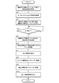
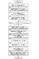
- the processor 21 of the analyzer 7 implements the evaluation method of the shaft joint 4. Therefore, the evaluation program is executed to perform the evaluation process shown in the flowchart of FIG. The details of the evaluation process will be described below with reference to FIG. However, when the evaluation process is started, it is assumed that the shaft joint 4 is not connected to either the drive shaft 2 or the driven shaft 3.
- the frequency characteristic acquisition unit 32 first acquires the frequency characteristic (ST1). As a result, the drive motor 11 is driven in a state where the shaft joint 4 is not connected to the drive shaft 2 and the driven shaft 3, and the frequency characteristics are acquired. After that, the motor system response acquisition unit 33 acquires the response characteristics of the motor system 5 by using the frequency characteristics acquired when the shaft joint 4 is not connected to the drive shaft 2 and the driven shaft 3 (ST2). More specifically, the motor system response acquisition unit 33 acquires the response band w, which is a parameter included in the transfer function G * (s), from the frequency characteristics in a state where the shaft joint 4 is not connected.
- the processor 21 displays a screen prompting the output device 28 to connect the drive shaft 2 and the driven shaft 3 by the shaft joint 4, and the shaft joint 4 to be evaluated of the corresponding shaft joint 4 is displayed. It accepts the input of the moment of inertia J c (ST3). After that, the processor 21 determines whether or not the user has input the moment of inertia J c of the shaft joint 4 to the input device 27 (ST4). When there is an input, the frequency characteristic acquisition unit 32 acquires the frequency characteristic (ST5). As a result, the frequency characteristic in the state where the shaft joint 4 is connected is acquired. If there is no input, the user waits until the input device 27 receives an input indicating that the connection of the shaft joint 4 is completed.
- the shaft joint characteristic evaluation unit 34 determines the resonance frequency f 0 and the resonance frequency f of the shaft joint 4 from the frequency characteristic in the state where the shaft joint 4 is connected. obtains the gain (gain) G f0 in 0 (ST6).
- the shaft joint characteristic evaluation unit 34 calculates the torsional rigidity K c of the shaft joint 4 using the equation (1) using the resonance frequency f 0 (ST7). Thereafter, the shaft coupling characteristic evaluation unit 34 on the basis of the equation (3), calculate the velocity response parameter exp M f0 from the gain exp G f0 at the resonance frequency f 0 (ST8). Further, the shaft joint characteristic evaluation unit 34 uses the response band w to convert the calculated speed response parameter exp M f0 into a converted speed response parameter M fo corresponding to the speed response parameter (ST9). Thereafter, the shaft coupling characteristic evaluation unit 34, the torsional stiffness K c, and conversion rate responsive parameter M fo, using equation (5) to calculate the viscosity coefficient c c shaft coupling 4. Shaft coupling characteristic evaluation unit 34, the calculation of the viscosity coefficient c c shaft coupling 4 is completed, and displays the torsional stiffness K c and the viscosity coefficient c c calculated for the output device 28 (ST10).
- the processor 21 finishes the evaluation process.
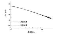
- the frequency characteristic in a state where the shaft joint 4 is not connected to the drive shaft 2 and the driven shaft 3 is acquired (ST1).
- the frequency characteristics acquired at this time are shown by solid lines.
- the motor system response acquisition unit 33 fits the transfer function corresponding to the block diagram corresponding to the state in which the shaft joint 4 is not connected to the acquired frequency characteristic by the least squares method, and the response band w. Is calculated and the transfer function G * (s) is acquired (ST2).
- the response band w is 1200 rad / s ( ⁇ 191 Hz at the cutoff frequency). It is calculated.
- the frequency characteristic calculated using the calculated response band w is shown by a broken line. As shown by the broken line in FIG. 4, the frequency characteristic in the state where the shaft joint 4 is not connected can be reproduced by the theoretically calculated response band w, so that the motor system 5 is sufficient as a primary delay system. It is considered that the response band w can be approximated and calculated accurately. Further, in FIG. 4, it can be confirmed that the measured gain G is gently bent in the vicinity of the cutoff frequency (w / 2 ⁇ ) corresponding to the response band w.
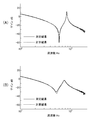
- FIG. 10A shows the measurement results of the frequency characteristics in the state where the shaft joint A connects both shafts.
- the shaft coupling characteristic evaluation unit 34 obtains the gain exp G f0 at the resonance frequency f 0, and the resonance frequency f 0 from the frequency characteristic acquired in a state where the shaft coupling 4 connects the drive shaft 2 and the driven shaft 3 (ST6). Thereafter, the shaft coupling characteristic evaluation unit 34 calculates a torsional stiffness K c of the shaft coupling 4 with a resonance frequency f 0 (ST7), and calculates the velocity response parameter exp M f0 from the gain exp G f0 in the resonance frequency f 0 (ST8). Further, the shaft joint characteristic evaluation unit 34 converts the speed response parameter exp M f0 into the converted speed response parameter M fo (ST9) using the response band w, and then calculates the viscosity coefficient c c (ST10).
- the torsional rigidity K c is calculated to be 5026 Nm / rad and the viscosity coefficient c c is calculated to be 0.0142 Nm / (rad / s) based on the frequency characteristics shown in FIG. 10 (A).
- the evaluation process is completed.
- FIG. 10B shows the measurement results of the frequency characteristics when the characteristics of the shaft joint B different from the shaft joint A are evaluated in the same manner.
- the torsional rigidity K c is calculated to be 5026 Nm / rad and the viscosity coefficient c c is calculated to be 0.0142 Nm / (rad / s) based on the frequency characteristics shown in FIG. 10 (B).
- the response band w Since the response band w is not affected by the rotational load or the evaluation shaft joint 4, when evaluating the characteristics of the shaft joint B after evaluating the characteristics of the shaft joint A, it is executed from step ST3 of the evaluation process. You may. In this way, the value of the response band w once determined can be used as it is for the test of the other shaft joint 4.
- FIGS. 10A and 10B the frequency characteristics calculated using the calculated torsional rigidity K c and the viscosity coefficient c c are shown by broken lines. As shown in FIGS. 10A and 10B, the frequency characteristics calculated using the torsional rigidity K c and the viscosity coefficient c c , and the frequency characteristics obtained by the measurement (frequency characteristics acquired in step ST1). ) Can be understood to indicate a good match.
- the motor system 5 has predetermined response characteristics, when the torque command T ref is input, the instantaneous driving torque T m which coincides with the torque command T ref does not occur to the drive shaft 2.
- the drive torque T m generated in the drive shaft 2 is given in until it matches the torque command T ref In some cases, it takes time (that is, delay time).
- the drive torque T m generated in the drive shaft 2 is the torque corresponding to the torque command Tref (that is, the transmission from the torque command Tref to the drive torque T m, especially at a frequency higher than the cutoff frequency. It is smaller than the torque when the function is assumed to be 1. That is, the gain obtained by measuring using the motor system 5 is a model that does not consider the response characteristics of the motor system 5, especially in a frequency band higher than the cutoff frequency, that is, the drive torque T m from the torque command Tref.
- the transfer function up to is 1, and after the torque command T ref is input, the gain becomes smaller than the gain expected based on the model in which the drive torque T m corresponding to the torque command T ref is instantly generated.
- the calculated physical parameters are the original physics of the shaft joint 4. It may differ from the value of the parameter, that is, the true value.
- the resonance frequency f 0 is larger than the response band w (191 Hz)
- physical parameters are used using a model that does not consider the response characteristics of the motor system 5. Is calculated, it is predicted that the difference between the calculated physical parameter and the true value will be large.
- the response characteristics of the motor system 5 with respect to the frequency characteristics acquired with the shaft joint A connected.
- the torsional rigidity K c and the viscosity coefficient c c were calculated ignoring. More specifically, the torsional rigidity K c and the viscosity coefficient c c were obtained by assuming that the measured velocity response parameter exp M f0 was M f0 and substituting it into the equation (5).
- the obtained torsional rigidity K c and the viscosity coefficient c c were 5026 Nm / rad and 0.0380 Nm / (rad / s), respectively.
- the frequency characteristics acquired with the shaft joint A connected are calculated using the solid line, the torsional rigidity K c acquired ignoring the response characteristics of the motor system 5, and the viscosity coefficient c c.
- the frequency characteristics are shown by two-dot chain lines.
- FIG. 10 (A) it can be understood that the measured frequency characteristic (solid line) and the calculated frequency characteristic (broken line) are different from each other as compared with the case of FIG. 10 (A). That is, as shown in FIG. 10A, the characteristic evaluation device 1 according to the present invention can reproduce the frequency characteristics measured more accurately by calculation (simulation), so that the physical parameters of the shaft joint 4 to be identified can be determined. It can be understood that it is closer to the true value.
- the characteristic evaluation device 1 by using the characteristic evaluation device 1, the response characteristics from when the torque command Tref is given to the motor to calculate the characteristics of the shaft joint 4 until the drive torque T m is generated by the drive motor 11 are considered. This makes it possible to more appropriately evaluate the characteristics of the shaft joint 4.
- characteristic evaluation apparatus (characteristic evaluation method)
- it is possible to obtain the torsional stiffness K c and the viscosity coefficient c c shaft coupling 4 allows inspection of the characteristics of the shaft coupling 4 It becomes.
- the input torque command Tref and changing the amplitude of the torque output from the drive motor 11 for evaluation, it is clarified how the characteristics of the shaft joint 4 change depending on the usage state. can do.
- the torsional stiffness K c and the viscosity coefficient c c shaft coupling 4 obtained by the characteristic evaluation apparatus 1 to simulate the characteristics of the machine in which the shaft coupling 4 is incorporated more accurately.
- the value of the response band w once determined can be used as it is for the test of the other shaft joint 4, it is not necessary to acquire the response band w every time the shaft joint 4 is replaced, and a plurality of shaft joints 4 are used. The characteristics of the above can be evaluated more quickly.
- Second Embodiment A dependency characteristic evaluation apparatus 101 according to the second embodiment with respect to the amplitude of the torque command T ref torsional stiffness K c of the shaft coupling 4, the dependence on the amplitude of the torque command T ref of the viscosity coefficient c c shaft coupling 4 To get.
- the processor 21 of the characteristic evaluation device 101 according to the second embodiment executes an evaluation program different from that of the evaluation device 1 according to the first embodiment, and an evaluation process different from that of the first embodiment. I do.
- the details of the evaluation process will be described with reference to FIG. However, as in the first embodiment, when the evaluation process is started, it is assumed that the shaft joint 4 is not connected to either the drive shaft 2 or the driven shaft 3.
- the processor 21 receives a plurality of torque amplitude values for instructing the servo driver 13 to output (ST11). At this time, when the upper limit value and the lower limit value of the amplitude and the number of the amplitude values to be set are input to the input / output device 8, the processor 21 sets the number of the values between the upper limit value and the lower limit value.
- the value of the amplitude of the torque for giving the output instruction may be accepted by dividing based on the above.
- the frequency characteristic acquisition unit 32 outputs a torque command Tref so as to output the torque vibrating with the amplitude received by the servo driver 13 while changing the frequency, and acquires the frequency characteristics at each amplitude (ST12). ..
- the drive motor 11 is driven in a state where the shaft joint 4 is not connected to the drive shaft 2 and the driven shaft 3, and the frequency characteristics at the respective amplitudes are acquired.
- the motor system response acquisition unit 33 acquires the response characteristics of the motor system 5 at each amplitude by using the frequency characteristics acquired when the shaft joint 4 is not connected to the drive shaft 2 and the driven shaft 3 ( ST13). More specifically, the motor system response acquisition unit 33 acquires the response band w, which is a parameter included in the transfer function G * (s), from the frequency characteristics of the respective amplitudes in a state where the shaft joint 4 is not connected. ..
- the processor 21 displays a screen prompting the output device 28 to connect the drive shaft 2 and the driven shaft 3 by the shaft joint 4, and the shaft joint 4 to be evaluated of the corresponding shaft joint 4 is displayed.
- the input of the moment of inertia J c is accepted (ST14).
- the processor 21 determines whether or not the user has input the moment of inertia J c of the shaft joint 4 to the input device 27 (ST15).
- the frequency characteristic acquisition unit 32 When the moment of inertia J c is input, the frequency characteristic acquisition unit 32 outputs a torque command Tref so as to output a torque that vibrates with the input amplitude while changing the frequency, and each amplitude. (ST16). As a result, the frequency characteristics in the state where the shaft joint 4 is connected at each amplitude are acquired. If there is no input, the user waits until the input device 27 receives an input indicating that the connection of the shaft joint 4 is completed.
- the shaft joint characteristic evaluation unit 34 obtains each frequency characteristic from the frequency characteristics with the shaft joint 4 connected. the resonance frequency f 0 of the shaft coupling 4 for the amplitude, and obtains the gain (gain) G f0 in the resonance frequency f 0 (ST17).
- the shaft joint characteristic evaluation unit 34 calculates the torsional rigidity K c of the shaft joint 4 with respect to each amplitude by using the resonance frequency f 0 at each amplitude and the equation (1) (ST18). After that, the shaft joint characteristic evaluation unit 34 calculates the velocity response parameter exp M f0 for each amplitude from the gain exp G f0 at the resonance frequency f 0 based on the equation (3) (ST19).
- the shaft joint characteristic evaluation unit 34 uses the response band w to convert the velocity response parameter exp M f0 calculated for each amplitude into the converted velocity response parameter M fo (ST20). After that, the shaft joint characteristic evaluation unit 34 calculates the viscosity coefficient c c of the shaft joint 4 at each amplitude using the equation (5) from the torsional rigidity K c at each amplitude and the converted speed response parameter M fo. (ST21). When the calculation of the viscosity coefficient c c of the shaft joint 4 is completed, the shaft joint characteristic evaluation unit 34 determines the relationship between the amplitude of the torque command T ref and the torsional rigidity K c , and the amplitude of the torque command T ref and the viscosity coefficient c c.
- the processor 21 finishes the evaluation process.
- the processor 21 of the characteristic evaluation device 101 of the shaft joint 4 servos a torque command T ref so as to output a drive torque T m having two or more amplitudes when the shaft joint 4 connects both shafts. It is output to the driver 13 (motor control unit) to calculate the frequency characteristics corresponding to each amplitude. Based on the response characteristics of the motor system 5 and the calculated frequency characteristics, the characteristics of the shaft joint 4 corresponding to each of the amplitudes are calculated.
- the processor 21 obtains the torsional rigidity K c and the viscosity coefficient c c of the shaft joint 4 for each of the acquired frequency characteristics, and determines the relationship between the amplitude and the torsional rigidity K c of the shaft joint 4. a relationship between the viscosity coefficient c c amplitude and shaft couplings 4 outputs graphically.
- the frequency characteristics of the gain of the shaft joint A are measured by changing the amplitude of the torque command Tref in 10 ways, and the torsional rigidity K c and the viscosity coefficient c c of the shaft joint A at each torque amplitude are measured.
- the horizontal axis is the amplitude of the torque command T ref and the vertical axis is the torsional rigidity K c
- the horizontal axis is the amplitude of the torque command T ref and the vertical axis is the viscosity coefficient c c.
- the solid lines in FIGS. 14A and 14B are approximate curves showing the tendency of change.
- the amplitude dependence of the torque command T ref torsional stiffness K c of the shaft coupling 4 and the amplitude dependence of the torque command T ref of the viscosity coefficient c c is output.
- the input-dependent characteristics of the shaft joint 4 can be appropriately evaluated.
- the amplitude dependence of the torque command T ref characteristics of shaft coupling 4 is outputted as the amplitude dependence of the torsional stiffness K c and the viscosity coefficient c c, easily its contents are understood to users, shaft coupling 4
- the convenience of the characteristic evaluation device 101 of the above is enhanced.
- the horizontal axis of the graph is the amplitude of the torque command Tref , but the present invention is not limited to this aspect.
- the horizontal axis of the graph, the amplitude of the torque command T ref, the amplitude of the drive torque T m at the resonance frequency f 0, the amplitude of the rotation angle of the motor shaft at the resonance frequency f 0 (drive shaft 2), a motor shaft at the resonance frequency f 0 It may be at least one of the amplitudes of the angular velocity ⁇ of (drive shaft 2).
- the amplitude of the rotation angle of the motor shaft at the resonance frequency f 0 (drive shaft 2), or, when the amplitude of the angular speed ⁇ of the motor shaft at the resonance frequency f 0 (drive shaft 2) and the horizontal axis represents the resonance frequency f 0 is measured
- the target shaft joint may be acquired in advance by measurement, design, or the like, or may be acquired based on the frequency characteristics acquired under a predetermined torque command Tref. .. Further, the resonance frequency f 0 may be obtained by using the frequency characteristics acquired in each of the torque command Tref , and the amplitude of the rotation angle or the amplitude of the angular velocity ⁇ corresponding to the resonance frequency f 0 may be used as the horizontal axis.
- the frequency characteristics at each of the amplitudes of the torque command Tref may be measured a plurality of times, or may be measured only once. When the frequency characteristics are measured a plurality of times, the repeatability of the results can also be evaluated.
- step ST12 the frequency characteristic corresponding to the amplitude of the input torque command Tref was acquired in the state where the shaft joint 4 was not connected to the drive shaft 2 and the driven shaft 3. , Not limited to this aspect. More specifically, when the change due to the amplitude of the torque command Tref of the frequency characteristic in the state where the shaft joint 4 is not connected to the drive shaft 2 and the driven shaft 3 is small, the amplitude of the input torque command Tref
- the frequency characteristics corresponding to the above may be substituted by the frequency characteristics acquired in each predetermined amplitude, and the processing after step ST12 may be performed.
- the shaft coupling characteristic evaluation unit 34, the input and output device 8, the torsional rigidity K c and the viscosity coefficient c c had been shown graphically the dependence on the amplitude of the torque command T ref, It is not limited to this aspect.
- the shaft joint characteristic evaluation unit 34 informs the input / output device 8 of the relationship between the amplitude of the torque command T ref and the torsional rigidity K c , or the relationship between the amplitude of the torque command T ref and the viscosity coefficient c c . It may be output by a function or the like.
Landscapes
- Physics & Mathematics (AREA)
- General Physics & Mathematics (AREA)
- Acoustics & Sound (AREA)
- Engineering & Computer Science (AREA)
- Power Engineering (AREA)
- Control Of Electric Motors In General (AREA)
- Testing Of Devices, Machine Parts, Or Other Structures Thereof (AREA)
Abstract
Description
本発明に係る評価装置1は、回転駆動する駆動軸2のトルクを従動軸3に伝達すべく、両軸を接続する軸継手4(カップリング)の特性を評価するための装置である。より具体的には、本発明に係る特性評価装置1によって、軸継手4の特性であるねじり剛性Kc[Nm/rad]、及び粘性係数cc[Nm/(rad/s)]をそれぞれ定量的に評価することができる。










第2実施形態に係る特性評価装置101は軸継手4のねじり剛性Kcのトルク指令Trefの振幅に対する依存性と、軸継手4の粘性係数ccのトルク指令Trefの振幅に対する依存性とを取得する。振幅依存性を取得するため、第2実施形態に係る特性評価装置101のプロセッサ21は、第1実施形態に係る評価装置1とは異なる評価プログラムを実行し、第1実施形態とは異なる評価処理を行う。以下、図12を参照して、評価処理の詳細について説明する。但し、第1実施形態と同様に、評価処理が開始されるときには、駆動軸2及び従動軸3のいずれにも軸継手4が接続されていないものとする。
2 :駆動軸
3 :従動軸
4 :軸継手
5 :モータシステム
6 :従動装置
7 :解析装置
8 :出入力装置
11 :駆動用モータ
12 :電流センサ
13 :サーボドライバ(モータ制御部)
14 :回転角センサ
15 :微分器
16 :サーボシステム
18 :回転負荷部
21 :プロセッサ
22 :メモリ
23 :RAM
24 :ROM
25 :記憶装置
26 :出入力ポート
27 :入力装置
28 :出力装置
31 :記憶部
32 :周波数特性取得部
33 :モータシステム応答取得部
34 :軸継手特性評価部
101 :第2実施形態に係る特性評価装置
G*(s) :伝達関数
Kc :ねじり剛性
Mfo :換算速度応答パラメータ(換算値)
Tm :駆動トルク
cc :粘性係数
f0 :共振周波数
w :応答帯域
ω :角速度
Claims (14)
- 駆動軸から従動軸にトルクを伝達するべく、前記両軸を接続する軸継手の特性評価を行う特性評価装置であって、
前記駆動軸に駆動トルクを付与する駆動用モータ、前記駆動軸の回転角を取得する回転角センサ、及び、与えられたトルク指令に基づいて、前記トルク指令に応じたトルクを出力させるべく、前記駆動用モータを制御するモータ制御部を含むモータシステムと、
前記従動軸に接続された回転負荷部と、
所定の前記駆動トルクを出力するように前記トルク指令を前記モータ制御部に出力するとともに、前記回転角センサによって検出される前記回転角に基づいて、前記トルク指令に対応するトルクの振幅に対する前記回転角の角速度の振幅の利得の周波数特性を算出可能なプロセッサとを有し、
前記プロセッサは、前記モータシステムの応答特性と、前記軸継手が前記両軸を接続する状態において算出された前記周波数特性とに基づいて、前記軸継手の特性を算出することを特徴とする軸継手の特性評価装置。 - 前記プロセッサは、
前記モータシステムの応答特性として、前記トルク指令によって前記駆動用モータが駆動し、前記駆動用モータから対応するトルクが発生するまでの伝達関数を用い、
前記軸継手を接続した状態で前記周波数特性を取得し、
前記周波数特性から前記軸継手の共振周波数、及び、前記共振周波数における前記利得を取得し、
前記共振周波数を用いて、前記軸継手のねじり剛性を算出し、
前記伝達関数、前記ねじり剛性、及び前記共振周波数における前記利得を用いて、前記軸継手の粘性係数を算出することを特徴とする請求項1に記載の軸継手の特性評価装置。 - 前記プロセッサは、
前記共振周波数における前記利得を、前記伝達関数を用いて、前記伝達関数が1の場合の前記共振周波数における前記利得に対応する換算値に換算し、
前記ねじり剛性と、前記換算値とを用いて、前記軸継手の粘性係数を算出することを特徴とする請求項2に記載の軸継手の特性評価装置。 - 前記プロセッサは、前記モータシステムの応答特性を、前記両軸に前記軸継手が接続されていない状態で前記駆動用モータが駆動されたときの前記周波数特性によって取得することを特徴とする請求項1~請求項3のいずれか1つの項に記載の軸継手の特性評価装置。
- 駆動軸から従動軸にトルクを伝達するべく、前記両軸を接続する軸継手の特性評価を行う軸継手の特性評価方法であって、
前記駆動軸に駆動トルクを付与する駆動用モータ、前記駆動軸の回転角を取得する回転角センサ、及び、与えられたトルク指令に基づいて、前記トルク指令に応じたトルクを出力させるべく、前記駆動用モータを制御するモータ制御部を含むモータシステムと、
前記従動軸に接続された回転負荷部と、
所定の前記駆動トルクを出力するように前記トルク指令を前記モータ制御部に出力するとともに、前記回転角センサによって検出される前記回転角に基づいて、前記トルク指令に対応するトルクの振幅に対する前記回転角の角速度の振幅の利得の周波数特性を算出可能な特性評価装置を用いて、
前記軸継手が前記両軸を接続する状態において前記周波数特性を取得するステップと、
取得された前記周波数特性、及び、前記モータシステムの応答特性に基づいて、前記軸継手の特性を算出するステップとを実行することを特徴とする軸継手の特性評価方法。 - 前記軸継手を接続した状態で前記周波数特性を取得するステップと、
前記周波数特性から前記軸継手の共振周波数、及び、前記共振周波数における前記利得を取得するステップと、
前記共振周波数を用いて、前記軸継手のねじり剛性を算出するステップと、
前記モータシステムの応答特性としての前記トルク指令によって前記駆動用モータが駆動し、前記駆動用モータから対応するトルクが発生するまでの伝達関数、前記ねじり剛性、及び前記共振周波数における前記利得を用いて、前記軸継手の粘性係数を算出するステップとを含むことを特徴とする請求項5に記載の軸継手の特性評価方法。 - 前記軸継手の粘性係数を算出する前記ステップは、
前記共振周波数における前記利得を、前記伝達関数を用いて、前記伝達関数が1の場合の前記共振周波数における前記利得に対応する換算値に換算するステップと、
前記ねじり剛性と、前記換算値とを用いて、前記軸継手の粘性係数を算出するステップとを含むことを特徴とする請求項6に記載の軸継手の特性評価方法。 - 前記モータシステムの応答特性を、前記両軸に前記軸継手が接続されていない状態で前記駆動用モータが駆動されたときの前記周波数特性によって取得するステップを含むことを特徴とする請求項5~請求項7のいずれか1つの項に記載の軸継手の特性評価方法。
- 前記プロセッサは、前記軸継手が前記両軸を接続する状態において2つ以上の振幅の前記駆動トルクを出力するように前記トルク指令を前記モータ制御部に出力して、それぞれの前記振幅に対応する前記周波数特性を算出し、前記モータシステムの応答特性と、算出された前記周波数特性とに基づいて、前記振幅のそれぞれに対応する前記軸継手の特性を算出し、前記トルク指令の前記振幅、前記軸継手の共振周波数における前記駆動トルクの振幅、前記共振周波数における前記回転角の振幅、前記共振周波数における前記角速度の振幅の少なくともいずれか一つと前記軸継手の特性との関係を出力することを特徴とする請求項1に記載の軸継手の特性評価装置。
- 前記プロセッサは、取得した前記周波数特性それぞれに対して、前記軸継手のねじり剛性を求め、前記トルク指令の前記振幅、前記共振周波数における前記駆動トルクの振幅、前記共振周波数における前記回転角の振幅、前記共振周波数における前記角速度の振幅の少なくともいずれか一つと、前記軸継手のねじり剛性との関係を出力することを特徴とする請求項9に記載の軸継手の特性評価装置。
- 前記プロセッサは、2つ以上の振幅の前記駆動トルクを出力するように前記トルク指令を前記モータ制御部に出力して、それぞれの前記振幅に対応する前記周波数特性を取得し、取得した前記周波数特性それぞれに対して、前記軸継手の粘性係数を求め、前記トルク指令の前記振幅、前記共振周波数における前記駆動トルクの振幅、前記共振周波数における前記回転角の振幅、前記共振周波数における前記角速度の振幅の少なくともいずれか一つと、前記軸継手の粘性係数との関係を出力することを特徴とする請求項9及び請求項10に記載の軸継手の特性評価装置。
- 前記軸継手が前記両軸を接続する状態で、2つ以上の振幅の前記駆動トルクを前記モータシステムに出力させて、それぞれの前記振幅に対応する前記周波数特性を取得するステップと、
取得された前記周波数特性、及び、前記モータシステムの応答特性に基づいて、それぞれの前記振幅に対応する前記軸継手の特性を算出するステップとを実行することを特徴とする請求項5に記載の軸継手の特性評価方法。 - 前記軸継手を接続した状態で、2つ以上の振幅の前記周波数特性を取得するステップと、
それぞれの前記周波数特性から前記軸継手の共振周波数、及び、前記共振周波数における前記利得を取得するステップと、
前記共振周波数を用いて、それぞれの前記振幅に対応する前記軸継手のねじり剛性を算出するステップと、
前記トルク指令の前記振幅、前記共振周波数における前記駆動トルクの振幅、前記共振周波数における前記回転角の振幅、前記共振周波数における前記角速度の振幅の少なくともいずれか一つと、前記軸継手の前記ねじり剛性との関係を出力するステップとを含むことを特徴とする請求項12に記載の軸継手の評価方法。 - それぞれの前記振幅において、前記モータシステムの応答特性としての前記トルク指令によって前記駆動用モータが駆動し、前記駆動用モータから対応するトルクが発生するまでの伝達関数、前記ねじり剛性、及び前記共振周波数における前記利得を用いて、前記軸継手の粘性係数を算出するステップと、
前記トルク指令の前記振幅、前記共振周波数における前記駆動トルクの振幅、前記共振周波数における前記回転角の振幅、前記共振周波数における前記角速度の振幅の少なくともいずれか一つと、前記軸継手の粘性係数との関係を出力するステップとを含むことを特徴とする請求項13に記載の軸継手の特性評価方法。
Priority Applications (5)
| Application Number | Priority Date | Filing Date | Title |
|---|---|---|---|
| DE112020003348.1T DE112020003348T5 (de) | 2019-08-09 | 2020-08-07 | Kennlinienauswertevorrichtung und Kennlinienauswerteverfahren von einer Wellenkupplung |
| KR1020227006526A KR102579617B1 (ko) | 2019-08-09 | 2020-08-07 | 축 커플링의 특성 평가 장치 및 특성 평가 방법 |
| CN202080056234.1A CN114207402B (zh) | 2019-08-09 | 2020-08-07 | 联轴器的特性评价装置和特性评价方法 |
| US17/633,774 US12021466B2 (en) | 2019-08-09 | 2020-08-07 | Characteristic evaluation device and characteristic evaluation method of shaft coupling |
| BR112022001057-5A BR112022001057B1 (pt) | 2019-08-09 | 2020-08-07 | Dispositivo de avaliação de característica e método de avaliação de característica de acoplamento de eixo |
Applications Claiming Priority (4)
| Application Number | Priority Date | Filing Date | Title |
|---|---|---|---|
| JP2019147561 | 2019-08-09 | ||
| JP2019-147561 | 2019-08-09 | ||
| JP2020110679A JP7016115B2 (ja) | 2019-08-09 | 2020-06-26 | 軸継手の特性評価装置及び特性評価方法 |
| JP2020-110679 | 2020-06-26 |
Publications (1)
| Publication Number | Publication Date |
|---|---|
| WO2021029366A1 true WO2021029366A1 (ja) | 2021-02-18 |
Family
ID=74569502
Family Applications (1)
| Application Number | Title | Priority Date | Filing Date |
|---|---|---|---|
| PCT/JP2020/030395 Ceased WO2021029366A1 (ja) | 2019-08-09 | 2020-08-07 | 軸継手の特性評価装置及び特性評価方法 |
Country Status (5)
| Country | Link |
|---|---|
| US (1) | US12021466B2 (ja) |
| KR (1) | KR102579617B1 (ja) |
| CN (1) | CN114207402B (ja) |
| DE (1) | DE112020003348T5 (ja) |
| WO (1) | WO2021029366A1 (ja) |
Cited By (2)
| Publication number | Priority date | Publication date | Assignee | Title |
|---|---|---|---|---|
| CN115096721A (zh) * | 2022-05-30 | 2022-09-23 | 大连理工大学 | 花键连接结构接触刚度识别装置及识别方法 |
| CN119090273A (zh) * | 2024-08-29 | 2024-12-06 | 中国长江三峡集团有限公司 | 压缩空气储能系统轴系振荡风险的评估方法及装置 |
Citations (5)
| Publication number | Priority date | Publication date | Assignee | Title |
|---|---|---|---|---|
| JPH08136408A (ja) * | 1994-11-09 | 1996-05-31 | Meidensha Corp | ダイナモメータ |
| JP2014122804A (ja) * | 2012-12-20 | 2014-07-03 | Toyota Motor Corp | 変速機構の試験方法 |
| CN104634569A (zh) * | 2015-03-11 | 2015-05-20 | 重庆理工大学 | 一种联轴器扭转刚度及扭转阻尼动态测量方法 |
| JP2018007287A (ja) * | 2016-06-27 | 2018-01-11 | 株式会社明電舎 | モータドライブシステム |
| JP2018173702A (ja) * | 2017-03-31 | 2018-11-08 | 三菱重工業株式会社 | パラメータ同定装置、駆動システム、パラメータ同定方法及びプログラム |
Family Cites Families (20)
| Publication number | Priority date | Publication date | Assignee | Title |
|---|---|---|---|---|
| US2332068A (en) | 1941-02-10 | 1943-10-19 | Christiane Ganna Fast | Coupling |
| JPH0442762Y2 (ja) * | 1988-11-14 | 1992-10-09 | ||
| JPH0716115B2 (ja) * | 1989-03-03 | 1995-02-22 | 富士通株式会社 | 小型装置をシェルフ内に取付けるための構造 |
| JP2750626B2 (ja) | 1990-03-30 | 1998-05-13 | キヤノン株式会社 | 位置決め装置の粘性摩擦係数同定方法 |
| DE4403477C1 (de) | 1994-02-04 | 1995-04-06 | Kirschey Centa Antriebe | Wellenkupplung |
| JP2000155058A (ja) * | 1998-11-19 | 2000-06-06 | Mitsubishi Heavy Ind Ltd | トルク付加試験方法およびトルク付加試験装置 |
| JP2003341537A (ja) * | 2002-05-22 | 2003-12-03 | Koyo Seiko Co Ltd | 電動パワーステアリング装置 |
| JP2005214711A (ja) * | 2004-01-28 | 2005-08-11 | Matsushita Electric Ind Co Ltd | 制御対象の機械特性の測定装置及び測定方法 |
| JP2005325980A (ja) | 2004-05-17 | 2005-11-24 | Koyo Seiko Co Ltd | 軸継手監視装置 |
| JP4576530B2 (ja) * | 2005-03-30 | 2010-11-10 | 国立大学法人東京農工大学 | サーボゲイン算出方法、サーボゲイン算出プログラム及びサーボゲイン算出装置 |
| JP2008309605A (ja) * | 2007-06-14 | 2008-12-25 | Ono Sokki Co Ltd | シャシダイナモメータの制御装置及びエンジンダイナモメータの制御装置 |
| JP5304913B2 (ja) * | 2012-03-02 | 2013-10-02 | 株式会社明電舎 | ダイナモメータシステム |
| JP5728457B2 (ja) * | 2012-10-31 | 2015-06-03 | 三木プーリ株式会社 | 撓み軸継手およびその製造方法 |
| JP6007831B2 (ja) * | 2013-03-12 | 2016-10-12 | シンフォニアテクノロジー株式会社 | 動力系の試験装置 |
| JP5490335B1 (ja) * | 2013-06-03 | 2014-05-14 | 三菱電機株式会社 | 周波数応答測定装置 |
| JP6697313B2 (ja) * | 2016-04-08 | 2020-05-20 | オークマ株式会社 | 送り軸制御装置における周波数特性測定方法 |
| JP6710103B2 (ja) * | 2016-05-25 | 2020-06-17 | 三菱重工業株式会社 | パラメータ同定装置、モータ制御システム、パラメータ同定方法及びプログラム |
| CN107036806B (zh) * | 2016-12-08 | 2023-07-11 | 华南理工大学 | 一种rv减速器迟滞曲线测试装置及方法 |
| CN111194386B (zh) | 2017-09-29 | 2022-07-05 | 莱雅公司 | 驱动轴联接器 |
| JP6481792B2 (ja) * | 2018-03-26 | 2019-03-13 | シンフォニアテクノロジー株式会社 | 動力系の試験装置 |
-
2020
- 2020-08-07 DE DE112020003348.1T patent/DE112020003348T5/de active Granted
- 2020-08-07 KR KR1020227006526A patent/KR102579617B1/ko active Active
- 2020-08-07 WO PCT/JP2020/030395 patent/WO2021029366A1/ja not_active Ceased
- 2020-08-07 CN CN202080056234.1A patent/CN114207402B/zh active Active
- 2020-08-07 US US17/633,774 patent/US12021466B2/en active Active
Patent Citations (5)
| Publication number | Priority date | Publication date | Assignee | Title |
|---|---|---|---|---|
| JPH08136408A (ja) * | 1994-11-09 | 1996-05-31 | Meidensha Corp | ダイナモメータ |
| JP2014122804A (ja) * | 2012-12-20 | 2014-07-03 | Toyota Motor Corp | 変速機構の試験方法 |
| CN104634569A (zh) * | 2015-03-11 | 2015-05-20 | 重庆理工大学 | 一种联轴器扭转刚度及扭转阻尼动态测量方法 |
| JP2018007287A (ja) * | 2016-06-27 | 2018-01-11 | 株式会社明電舎 | モータドライブシステム |
| JP2018173702A (ja) * | 2017-03-31 | 2018-11-08 | 三菱重工業株式会社 | パラメータ同定装置、駆動システム、パラメータ同定方法及びプログラム |
Cited By (2)
| Publication number | Priority date | Publication date | Assignee | Title |
|---|---|---|---|---|
| CN115096721A (zh) * | 2022-05-30 | 2022-09-23 | 大连理工大学 | 花键连接结构接触刚度识别装置及识别方法 |
| CN119090273A (zh) * | 2024-08-29 | 2024-12-06 | 中国长江三峡集团有限公司 | 压缩空气储能系统轴系振荡风险的评估方法及装置 |
Also Published As
| Publication number | Publication date |
|---|---|
| DE112020003348T5 (de) | 2022-03-24 |
| BR112022001057A2 (pt) | 2022-05-24 |
| US20220278638A1 (en) | 2022-09-01 |
| CN114207402A (zh) | 2022-03-18 |
| KR20220039786A (ko) | 2022-03-29 |
| US12021466B2 (en) | 2024-06-25 |
| CN114207402B (zh) | 2024-09-13 |
| KR102579617B1 (ko) | 2023-09-15 |
Similar Documents
| Publication | Publication Date | Title |
|---|---|---|
| Frey et al. | Expedient modeling of ball screw feed drives | |
| US10180382B2 (en) | Viscoelasticity measurement method and viscoelasticity measurement device | |
| JP6659491B2 (ja) | エンジン試験装置 | |
| WO2021029366A1 (ja) | 軸継手の特性評価装置及び特性評価方法 | |
| CN111537170A (zh) | 一种伺服作动器动刚度测试方法 | |
| CN102507056B (zh) | 滚动轴承摩擦力矩动态跟踪测量仪 | |
| CN110346082B (zh) | 游梁式抽油机悬点受力测量系统的标定方法 | |
| JP6659492B2 (ja) | エンジン試験装置 | |
| CN113189865B (zh) | 基于动力学参数辨识的康复机器人控制系统 | |
| JP7016115B2 (ja) | 軸継手の特性評価装置及び特性評価方法 | |
| JP5831903B2 (ja) | 粘弾性測定方法及び粘弾性測定装置 | |
| CN100517135C (zh) | 自动控制模拟系统及自动控制模拟方法 | |
| HK40067942A (en) | Shaft coupling characterization device and characterization method | |
| JP4019710B2 (ja) | エンジンベンチシステム | |
| HK40067942B (zh) | 联轴器的特性评价装置和特性评价方法 | |
| JP5831904B2 (ja) | 粘弾性測定方法及び粘弾性測定装置 | |
| CN107168060B (zh) | 基于继电反馈技术的带弹簧伺服系统辨识方法 | |
| JP6697313B2 (ja) | 送り軸制御装置における周波数特性測定方法 | |
| BR112022001057B1 (pt) | Dispositivo de avaliação de característica e método de avaliação de característica de acoplamento de eixo | |
| Brack et al. | Simultaneous and continuous measurement of shear elasticity and viscosity of liquids at multiple discrete frequencies | |
| CN204575249U (zh) | 一种封闭空间内转子不平衡量的快速调节装置 | |
| TW202131121A (zh) | 電子設備及其控制方法 | |
| JP4019711B2 (ja) | エンジンベンチシステムのシャフトばね定数計測方法 | |
| Chen et al. | A Calibration and Measurement Method for Rotational Viscometers Based on Kalman Filtering | |
| Dutta et al. | Smartphone Sensor-Based Experiments for Characterizing First and Second Order Systems |
Legal Events
| Date | Code | Title | Description |
|---|---|---|---|
| 121 | Ep: the epo has been informed by wipo that ep was designated in this application |
Ref document number: 20853418 Country of ref document: EP Kind code of ref document: A1 |
|
| REG | Reference to national code |
Ref country code: BR Ref legal event code: B01A Ref document number: 112022001057 Country of ref document: BR |
|
| ENP | Entry into the national phase |
Ref document number: 20227006526 Country of ref document: KR Kind code of ref document: A |
|
| REG | Reference to national code |
Ref country code: BR Ref legal event code: B01E Ref document number: 112022001057 Country of ref document: BR Free format text: APRESENTAR A TRADUCAO SIMPLES DA FOLHA DE ROSTO DA CERTIDAO DE DEPOSITO DAS PRIORIDADES JP 2019-147561 DE 09/08/2019 E JP 2020-110679 DE 26/06/2020 OU DECLARACAO CONTENDO, OBRIGATORIAMENTE, TODOS OS DADOS IDENTIFICADORES DESTAS CONFORME O ART. 15 DA PORTARIA 39/2021. OS DOCUMENTOS APRESENTADOS NAO ESTAO TRADUZIDOS E AS DECLARACOES NAO CONTEM OS DADOS IDENTIFICADORES DAS PRIORIDADES. |
|
| ENP | Entry into the national phase |
Ref document number: 112022001057 Country of ref document: BR Kind code of ref document: A2 Effective date: 20220119 |
|
| 122 | Ep: pct application non-entry in european phase |
Ref document number: 20853418 Country of ref document: EP Kind code of ref document: A1 |