WO2021024958A1 - 熱交換器 - Google Patents
熱交換器 Download PDFInfo
- Publication number
- WO2021024958A1 WO2021024958A1 PCT/JP2020/029541 JP2020029541W WO2021024958A1 WO 2021024958 A1 WO2021024958 A1 WO 2021024958A1 JP 2020029541 W JP2020029541 W JP 2020029541W WO 2021024958 A1 WO2021024958 A1 WO 2021024958A1
- Authority
- WO
- WIPO (PCT)
- Prior art keywords
- tube
- joined
- bent portion
- fin
- heat exchanger
- Prior art date
Links
- 239000012530 fluid Substances 0.000 claims abstract description 43
- 238000013459 approach Methods 0.000 claims description 8
- XLYOFNOQVPJJNP-UHFFFAOYSA-N water Substances O XLYOFNOQVPJJNP-UHFFFAOYSA-N 0.000 description 67
- 239000003507 refrigerant Substances 0.000 description 14
- 230000000052 comparative effect Effects 0.000 description 5
- 239000000463 material Substances 0.000 description 3
- 238000009423 ventilation Methods 0.000 description 3
- 238000005219 brazing Methods 0.000 description 2
- 230000000694 effects Effects 0.000 description 2
- 230000012447 hatching Effects 0.000 description 2
- 230000014759 maintenance of location Effects 0.000 description 2
- 238000005057 refrigeration Methods 0.000 description 2
- 238000004378 air conditioning Methods 0.000 description 1
- XAGFODPZIPBFFR-UHFFFAOYSA-N aluminium Chemical compound [Al] XAGFODPZIPBFFR-UHFFFAOYSA-N 0.000 description 1
- 229910052782 aluminium Inorganic materials 0.000 description 1
- 239000000470 constituent Substances 0.000 description 1
- 238000007599 discharging Methods 0.000 description 1
- 238000001704 evaporation Methods 0.000 description 1
- 230000008020 evaporation Effects 0.000 description 1
- 230000001737 promoting effect Effects 0.000 description 1
- 238000011144 upstream manufacturing Methods 0.000 description 1
- 238000009834 vaporization Methods 0.000 description 1
- 230000008016 vaporization Effects 0.000 description 1
Images


Classifications
-
- F—MECHANICAL ENGINEERING; LIGHTING; HEATING; WEAPONS; BLASTING
- F28—HEAT EXCHANGE IN GENERAL
- F28D—HEAT-EXCHANGE APPARATUS, NOT PROVIDED FOR IN ANOTHER SUBCLASS, IN WHICH THE HEAT-EXCHANGE MEDIA DO NOT COME INTO DIRECT CONTACT
- F28D1/00—Heat-exchange apparatus having stationary conduit assemblies for one heat-exchange medium only, the media being in contact with different sides of the conduit wall, in which the other heat-exchange medium is a large body of fluid, e.g. domestic or motor car radiators
- F28D1/02—Heat-exchange apparatus having stationary conduit assemblies for one heat-exchange medium only, the media being in contact with different sides of the conduit wall, in which the other heat-exchange medium is a large body of fluid, e.g. domestic or motor car radiators with heat-exchange conduits immersed in the body of fluid
- F28D1/04—Heat-exchange apparatus having stationary conduit assemblies for one heat-exchange medium only, the media being in contact with different sides of the conduit wall, in which the other heat-exchange medium is a large body of fluid, e.g. domestic or motor car radiators with heat-exchange conduits immersed in the body of fluid with tubular conduits
- F28D1/053—Heat-exchange apparatus having stationary conduit assemblies for one heat-exchange medium only, the media being in contact with different sides of the conduit wall, in which the other heat-exchange medium is a large body of fluid, e.g. domestic or motor car radiators with heat-exchange conduits immersed in the body of fluid with tubular conduits the conduits being straight
- F28D1/0535—Heat-exchange apparatus having stationary conduit assemblies for one heat-exchange medium only, the media being in contact with different sides of the conduit wall, in which the other heat-exchange medium is a large body of fluid, e.g. domestic or motor car radiators with heat-exchange conduits immersed in the body of fluid with tubular conduits the conduits being straight the conduits having a non-circular cross-section
- F28D1/05366—Assemblies of conduits connected to common headers, e.g. core type radiators
- F28D1/05391—Assemblies of conduits connected to common headers, e.g. core type radiators with multiple rows of conduits or with multi-channel conduits combined with a particular flow pattern, e.g. multi-row multi-stage radiators
-
- F—MECHANICAL ENGINEERING; LIGHTING; HEATING; WEAPONS; BLASTING
- F28—HEAT EXCHANGE IN GENERAL
- F28D—HEAT-EXCHANGE APPARATUS, NOT PROVIDED FOR IN ANOTHER SUBCLASS, IN WHICH THE HEAT-EXCHANGE MEDIA DO NOT COME INTO DIRECT CONTACT
- F28D7/00—Heat-exchange apparatus having stationary tubular conduit assemblies for both heat-exchange media, the media being in contact with different sides of a conduit wall
- F28D7/16—Heat-exchange apparatus having stationary tubular conduit assemblies for both heat-exchange media, the media being in contact with different sides of a conduit wall the conduits being arranged in parallel spaced relation
- F28D7/1615—Heat-exchange apparatus having stationary tubular conduit assemblies for both heat-exchange media, the media being in contact with different sides of a conduit wall the conduits being arranged in parallel spaced relation the conduits being inside a casing and extending at an angle to the longitudinal axis of the casing; the conduits crossing the conduit for the other heat exchange medium
-
- F—MECHANICAL ENGINEERING; LIGHTING; HEATING; WEAPONS; BLASTING
- F25—REFRIGERATION OR COOLING; COMBINED HEATING AND REFRIGERATION SYSTEMS; HEAT PUMP SYSTEMS; MANUFACTURE OR STORAGE OF ICE; LIQUEFACTION SOLIDIFICATION OF GASES
- F25B—REFRIGERATION MACHINES, PLANTS OR SYSTEMS; COMBINED HEATING AND REFRIGERATION SYSTEMS; HEAT PUMP SYSTEMS
- F25B39/00—Evaporators; Condensers
- F25B39/04—Condensers
-
- F—MECHANICAL ENGINEERING; LIGHTING; HEATING; WEAPONS; BLASTING
- F28—HEAT EXCHANGE IN GENERAL
- F28F—DETAILS OF HEAT-EXCHANGE AND HEAT-TRANSFER APPARATUS, OF GENERAL APPLICATION
- F28F1/00—Tubular elements; Assemblies of tubular elements
- F28F1/02—Tubular elements of cross-section which is non-circular
- F28F1/022—Tubular elements of cross-section which is non-circular with multiple channels
-
- F—MECHANICAL ENGINEERING; LIGHTING; HEATING; WEAPONS; BLASTING
- F28—HEAT EXCHANGE IN GENERAL
- F28F—DETAILS OF HEAT-EXCHANGE AND HEAT-TRANSFER APPARATUS, OF GENERAL APPLICATION
- F28F1/00—Tubular elements; Assemblies of tubular elements
- F28F1/10—Tubular elements and assemblies thereof with means for increasing heat-transfer area, e.g. with fins, with projections, with recesses
- F28F1/12—Tubular elements and assemblies thereof with means for increasing heat-transfer area, e.g. with fins, with projections, with recesses the means being only outside the tubular element
- F28F1/126—Tubular elements and assemblies thereof with means for increasing heat-transfer area, e.g. with fins, with projections, with recesses the means being only outside the tubular element consisting of zig-zag shaped fins
- F28F1/128—Fins with openings, e.g. louvered fins
-
- F—MECHANICAL ENGINEERING; LIGHTING; HEATING; WEAPONS; BLASTING
- F28—HEAT EXCHANGE IN GENERAL
- F28F—DETAILS OF HEAT-EXCHANGE AND HEAT-TRANSFER APPARATUS, OF GENERAL APPLICATION
- F28F1/00—Tubular elements; Assemblies of tubular elements
- F28F1/10—Tubular elements and assemblies thereof with means for increasing heat-transfer area, e.g. with fins, with projections, with recesses
- F28F1/12—Tubular elements and assemblies thereof with means for increasing heat-transfer area, e.g. with fins, with projections, with recesses the means being only outside the tubular element
- F28F1/24—Tubular elements and assemblies thereof with means for increasing heat-transfer area, e.g. with fins, with projections, with recesses the means being only outside the tubular element and extending transversely
- F28F1/30—Tubular elements and assemblies thereof with means for increasing heat-transfer area, e.g. with fins, with projections, with recesses the means being only outside the tubular element and extending transversely the means being attachable to the element
-
- F—MECHANICAL ENGINEERING; LIGHTING; HEATING; WEAPONS; BLASTING
- F28—HEAT EXCHANGE IN GENERAL
- F28F—DETAILS OF HEAT-EXCHANGE AND HEAT-TRANSFER APPARATUS, OF GENERAL APPLICATION
- F28F1/00—Tubular elements; Assemblies of tubular elements
- F28F1/10—Tubular elements and assemblies thereof with means for increasing heat-transfer area, e.g. with fins, with projections, with recesses
- F28F1/12—Tubular elements and assemblies thereof with means for increasing heat-transfer area, e.g. with fins, with projections, with recesses the means being only outside the tubular element
- F28F1/24—Tubular elements and assemblies thereof with means for increasing heat-transfer area, e.g. with fins, with projections, with recesses the means being only outside the tubular element and extending transversely
- F28F1/32—Tubular elements and assemblies thereof with means for increasing heat-transfer area, e.g. with fins, with projections, with recesses the means being only outside the tubular element and extending transversely the means having portions engaging further tubular elements
-
- F—MECHANICAL ENGINEERING; LIGHTING; HEATING; WEAPONS; BLASTING
- F28—HEAT EXCHANGE IN GENERAL
- F28F—DETAILS OF HEAT-EXCHANGE AND HEAT-TRANSFER APPARATUS, OF GENERAL APPLICATION
- F28F13/00—Arrangements for modifying heat-transfer, e.g. increasing, decreasing
- F28F13/18—Arrangements for modifying heat-transfer, e.g. increasing, decreasing by applying coatings, e.g. radiation-absorbing, radiation-reflecting; by surface treatment, e.g. polishing
-
- F—MECHANICAL ENGINEERING; LIGHTING; HEATING; WEAPONS; BLASTING
- F28—HEAT EXCHANGE IN GENERAL
- F28F—DETAILS OF HEAT-EXCHANGE AND HEAT-TRANSFER APPARATUS, OF GENERAL APPLICATION
- F28F17/00—Removing ice or water from heat-exchange apparatus
- F28F17/005—Means for draining condensates from heat exchangers, e.g. from evaporators
-
- F—MECHANICAL ENGINEERING; LIGHTING; HEATING; WEAPONS; BLASTING
- F28—HEAT EXCHANGE IN GENERAL
- F28D—HEAT-EXCHANGE APPARATUS, NOT PROVIDED FOR IN ANOTHER SUBCLASS, IN WHICH THE HEAT-EXCHANGE MEDIA DO NOT COME INTO DIRECT CONTACT
- F28D21/00—Heat-exchange apparatus not covered by any of the groups F28D1/00 - F28D20/00
- F28D2021/0019—Other heat exchangers for particular applications; Heat exchange systems not otherwise provided for
- F28D2021/008—Other heat exchangers for particular applications; Heat exchange systems not otherwise provided for for vehicles
- F28D2021/0085—Evaporators
-
- F—MECHANICAL ENGINEERING; LIGHTING; HEATING; WEAPONS; BLASTING
- F28—HEAT EXCHANGE IN GENERAL
- F28F—DETAILS OF HEAT-EXCHANGE AND HEAT-TRANSFER APPARATUS, OF GENERAL APPLICATION
- F28F2245/00—Coatings; Surface treatments
- F28F2245/02—Coatings; Surface treatments hydrophilic
Definitions
- This disclosure relates to heat exchangers.
- This heat exchanger includes a plurality of flat pipes and corrugated fins which are arranged between adjacent flat pipes and are joined to the flat pipes so that airflow passes through the gaps.
- a plurality of louvers as heat transfer promoting portions are formed on the surface of the corrugated fin, and a fluid path is provided on the corrugated fin and between the joint portion between the flat tube and the corrugated fin and the plurality of louvers. ing. In this heat exchanger, the water staying on the top of the corrugated fin flows vertically downward through the fluid path.
- Patent Document 1 cannot effectively drain the condensed water in the central portion of the corrugated fin sandwiched between two adjacent flat pipes.
- FIG. 21 it is conceivable to form a plurality of grooves 900 for increasing hydrophilicity on the surface of the corrugated fins 10 arranged between two adjacent tubes 20.
- a plurality of grooves 900 By forming such a plurality of grooves 900, the hydrophilicity of the surface of the corrugated fin 10 is enhanced, and the condensed water in the central portion C of the corrugated fin 10 sandwiched between the two adjacent tubes 20 is effectively drained. Is possible.
- heat exchangers are Multiple tubes through which the first fluid flows, A corrugated fin that enhances the efficiency of heat exchange between the first fluid flowing inside the tube and the second fluid flowing outside the tube.
- the corrugated fin is a fin body arranged between a plurality of bent portions joined to a tube and a bent portion joined to one adjacent tube and a bent portion joined to the other adjacent tube. With a part, On the surface of the fin body, a plurality of grooves extending from the bent portion joined to one tube toward the bent portion joined to the other tube are formed. In the middle of at least one groove of the plurality of grooves between the bent portion joined to one tube and the bent portion joined to the other tube, from the bottom of the groove toward the surface of the corrugated fin. A raised portion is formed.
- the heat exchanger is: Multiple tubes through which the first fluid flows, A corrugated fin that enhances the efficiency of heat exchange between the first fluid flowing inside the tube and the second fluid flowing outside the tube.
- the corrugated fin is a fin body arranged between a plurality of bent portions joined to a tube and a bent portion joined to one adjacent tube and a bent portion joined to the other adjacent tube.
- the fin body is formed with a plurality of grooves extending from a bent portion joined to one adjacent tube toward a bent portion joined to the other adjacent tube.
- the plurality of grooves between the bent portion joined to one tube and the bent portion joined to the other tube have a groove width of a predetermined length. In the middle of at least one groove of the plurality of grooves between the bent portion joined to one tube and the bent portion joined to the other tube, a narrow portion having a groove width narrower than a predetermined length is provided. It is formed.
- a groove longer than a predetermined length is formed in the middle of at least one groove of the plurality of grooves between the bent portion joined to one tube and the bent portion joined to the other tube.
- a narrow portion having a narrow width is formed in the middle of at least one groove of the plurality of grooves between the bent portion joined to one tube and the bent portion joined to the other tube. Therefore, when the flow rate of the condensed water from the tube is small, it is possible to prevent the condensed water from the tube from flowing toward the central portion between the adjacent tubes in the corrugated fin.
- heat exchangers are: Multiple tubes through which the first fluid flows, A corrugated fin that enhances the efficiency of heat exchange between the first fluid flowing inside the tube and the second fluid flowing outside the tube.
- the corrugated fin is a fin body arranged between a plurality of bent portions joined to a tube and a bent portion joined to one adjacent tube and a bent portion joined to the other adjacent tube. With a part, On the surface of the fin body, a plurality of grooves extending from the bent portion joined to one tube toward the bent portion joined to the other tube are formed. In the middle of at least two adjacent grooves between the bent part joined to one tube and the bent part joined to the other tube, there is an assembly part that collects at least two adjacent grooves.
- a branch portion that is connected to the portion and branches into a plurality of grooves is formed.
- a hydrophilicity reducing portion is formed between the collecting portion and the branching portion to reduce the hydrophilicity of the surface of the corrugated fin more than at least two grooves.
- two adjacent grooves are assembled in the middle of at least two adjacent grooves between the bent portion joined to one tube and the bent portion joined to the other tube.
- An gathering portion to be formed and a branch portion connected to the gathering portion and branched into a plurality of groove portions are formed.
- a hydrophilicity reducing portion is formed between the gathering portion and the branching portion to reduce the hydrophilicity of the surface of the corrugated fin more than at least two groove portions. Therefore, when the flow rate of the condensed water from the tube is small, it is possible to prevent the condensed water from the tube from flowing toward the central portion between the adjacent tubes in the corrugated fin.
- FIG. 1 It is a perspective view of the heat exchanger which concerns on 1st Embodiment. It is a partial enlarged view of a heat exchanger. It is a partial enlarged view of a heat exchanger. It is a partially enlarged view of a corrugated fin. It is a VV sectional view in FIG. It is a figure which showed the flow of condensed water in the comparative example in which the raised part was not formed in the middle of a plurality of groove parts. It is a figure which showed the flow of condensed water in the comparative example in which the raised part was not formed in the middle of a plurality of groove parts. It is a figure which showed the flow of condensed water in the heat exchanger which concerns on 1st Embodiment.
- FIG. 5 is an external view of a corrugated fin of the heat exchanger according to the fifth embodiment, and is a view of the fin main body from the direction of arrow XIII in FIG.
- FIG. 5 is an external view of a corrugated fin of the heat exchanger according to the fifth embodiment, and is a view of the fin main body from the direction of arrow XIII in FIG.
- It is a figure which represented typically the corrugated fin of the heat exchanger which concerns on 6th Embodiment.
- It is a figure which showed the region where condensed water collects in the corrugated fin of the heat exchanger which concerns on 6th Embodiment.
- the heat exchanger 1 of the present embodiment is used, for example, as an evaporator that constitutes a part of a refrigeration cycle that performs air conditioning in the vehicle interior.
- the evaporator exchanges heat between the refrigerant as the first fluid that circulates in the refrigeration cycle and the air as the second fluid that passes through the heat exchanger 1, and cools the air by the latent heat of evaporation of the refrigerant.
- the direction of air flow through the heat exchanger 1 is indicated by an arrow AF.
- the heat exchanger 1 includes a corrugated fin 10, a tube 20, a first header tank 21, a second header tank 22, a third header tank 23, a fourth header tank 24, and an outer frame member. 25, a pipe connecting member 26, and the like are provided. These members are made of, for example, aluminum, and the members are joined by brazing.
- the plurality of tubes 20 are arranged at predetermined intervals in a direction intersecting the air flow direction. Further, the plurality of tubes 20 are arranged in two rows on the upstream side and the downstream side in the air flow direction. Each of the plurality of tubes 20 extends linearly from one end to the other end. One end of the plurality of tubes 20 is inserted into the first header tank 21 or the second header tank 22, and the other end is inserted into the third header tank 23 or the fourth header tank 24.
- the first header tank 21, the second header tank 22, the third header tank 23, and the fourth header tank 24 distribute the refrigerant to the plurality of tubes 20 and collect the refrigerants flowing in from the plurality of tubes 20. is there.
- the corrugated fin 10 is provided in the air passage. That is, the corrugated fin 10 of the present embodiment is an outer fin provided on the outside of the tube 20.
- the corrugated fin 10 enhances the heat exchange efficiency between the refrigerant and the air by increasing the heat transfer area between the refrigerant flowing inside the tube 20 and the air flowing outside the tube 20.
- An outer frame member 25 is provided on the outside in the direction in which the plurality of tubes 20 and the plurality of corrugated fins 10 are alternately arranged.
- a pipe connecting member 26 is fixed to the outer frame member 25.
- the pipe connecting member 26 is provided with a refrigerant inlet 27 to which the refrigerant is supplied and a refrigerant outlet 28 for discharging the refrigerant.
- the refrigerant that has flowed into the first header tank 21 from the refrigerant inlet 27 flows through the header tanks 21 to 24 and the plurality of tubes 20 in a predetermined path, and flows out from the refrigerant outlet 28. At that time, the air flowing through the air passage provided with the corrugated fins 10 is cooled by the latent heat of vaporization of the refrigerant flowing through each of the header tanks 21 to 24 and the plurality of tubes 20.
- the corrugated fin 10 has a structure in which the plate-shaped members 100 are bent at predetermined intervals.
- the corrugated fin 10 has a plurality of bent portions 12 and a fin main body portion 13.
- the plurality of bent portions 12 are portions where the plate-shaped members 100 constituting the corrugated fin 10 are bent at predetermined intervals.
- the fin main body portion 13 is a portion arranged between the bent portion 12 and the bent portion 12.
- the fin body 13 is provided with a plurality of louvers 14 in which a part of the plate-shaped member 100 is cut and raised.
- the outer wall of the corrugated fin 10 on the tube 20 side and the outer wall of the tube 20 are joined by brazing.
- the surface of the corrugated fin 10 is provided with a plurality of fine groove portions 11 for increasing hydrophilicity. Specifically, a plurality of fine groove portions 11 are provided on both sides of the plate-shaped member 100. The plurality of groove portions 11 are provided so that the groove portions 11 are lined up at predetermined intervals. In each drawing referred to in the present embodiment, for the sake of explanation, a plurality of groove portions 11 provided on the surface of the corrugated fin 10 are schematically shown in large size. This also applies to the drawings referred to in the second to sixth embodiments described later.
- the plurality of groove portions 11 are provided in the bent portion 12 of the corrugated fin 10 and the fin main body portion 13. Further, the plurality of groove portions 11 are also provided in the louver 14. In the present embodiment, the plurality of groove portions 11 extend from the bent portion 12 joined to the one tube 20 toward the bent portion 12 joined to the other tube 20 in the plate-shaped fin main body portion 13. It is formed like this.
- the width of the groove 11 is preferably 10 to 50 ⁇ m.
- the depth of the groove 11 is preferably 10 ⁇ m or more.
- the pitch of the groove 11 is preferably 50 to 200 ⁇ m. This makes it possible to increase the hydrophilicity of the surface of the corrugated fin 10.
- the hydrophilicity of the surface of the corrugated fin 10 is increased, the drainage property of the corrugated fin 10 is improved, and the retention of condensed water on the surface of the corrugated fin 10 is suppressed. Therefore, since it is suppressed that the ventilation resistance of the air passage is increased due to the retention of the condensed water, the heat exchanger 1 can improve the heat exchange performance.
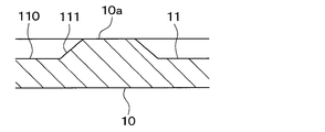
- the corrugated fin 10 of the present embodiment has two raised portions 111 in the middle of a plurality of groove portions 11 between the two bent portions 12 joined to the two tubes 20. It is formed.
- the two raised portions 111 are raised to the surface 10a of the corrugated fin 10.
- the plurality of groove portions 11 between the two bent portions 12 joined to the two tubes 20 by these raised portions 111 are divided at two points.
- a raised portion 111 is formed in the middle of a plurality of groove portions 11 between the two bent portions 12 joined to the two tubes 20. ing.
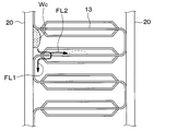
- the condensed water Wc generated on the tube 20 side flows toward the central portion between the two tubes 20 of the corrugated fin 10. It can be suppressed. That is, the raised portions 111 formed in the middle of the plurality of groove portions 11 prevent the condensed water Wc generated on the tube 20 side from advancing toward the central portion between the two tubes 20 of the corrugated fin 10. ..
- the arrow FL4 in FIG. 10 indicates.
- the condensed water Wc connects the condensed water Wc at both ends of the raised portion 111. Therefore, the condensed water Wc collected in the central portion between the two tubes 20 of the corrugated fin 10 flows downward beyond the portion where the raised portion 111 is formed as shown by the arrow FL1 in FIG. Therefore, drainage can be ensured.
- the heat exchanger 1 of the present embodiment includes a plurality of tubes 20 through which the first fluid flows. Further, the heat exchanger 1 includes corrugated fins 10 that increase the heat exchange efficiency between the first fluid flowing inside the tube 20 and the second fluid flowing outside the tube 20. Further, the corrugated fin 10 includes a plurality of bent portions 12 joined to the tube 20. Further, the corrugated fin 10 has a fin main body 13 arranged between a bent portion 12 joined to one adjacent tube 20 and a bent portion 12 joined to the other adjacent tube 20. ing. Further, on the surface of the fin main body portion 13, a plurality of groove portions 11 extending from the bent portion 12 joined to the one tube 20 toward the bent portion 12 joined to the other tube 20 are formed.
- a raised portion 111 is formed in the middle of the plurality of groove portions 11 between the bent portion 12 joined to one tube 20 and the bent portion 12 joined to the other tube 20.
- the raised portion 111 is raised from the bottom portion 110 of the groove portion 11 toward the surface 10a of the corrugated fin 10.
- the raised portion 111 is raised from the bottom portion 110 of the groove portion 11 to the surface 10a of the corrugated fin 10. As a result, the hydrophilicity of the region where the raised portion 111 is formed is greatly reduced, so that the condensed water from the tube 20 can more effectively flow toward the central portion between the adjacent tubes 20 in the corrugated fin 10. It can be suppressed.
- the heat exchanger 1 has at least two raised portions 111 in the middle of a plurality of groove portions 11 between the bent portion 12 joined to the one tube 20 and the bent portion 12 joined to the other tube 20. I have one.
- the heat exchanger 1 according to the second embodiment will be described with reference to FIG.
- the raised portion 111 of the first embodiment is raised from the bottom 110 of the groove 11 to the surface 10a of the corrugated fin 10.
- the raised portion 111 is raised from the bottom portion 110 of the groove portion 11 to a position lower than the surface 10a of the corrugated fin 10.
- the condensed water Wc generated on the tube 20 side is between the two tubes 20 of the corrugated fin 10. It is possible to suppress the launch to the central part.
- the same effect obtained from the configuration common to the first embodiment can be obtained in the same manner as in the first embodiment.
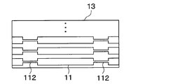
- a narrow groove portion 112 having a narrow groove width is formed in the middle of the plurality of groove portions 11.
- the plurality of groove portions 11 between the bent portion 12 joined to one tube 20 and the bent portion 12 joined to the other tube 20 have a groove width having a predetermined length.
- the groove width is narrower than the predetermined length. Part 112 is formed.
- the narrow width portion 112 suppresses the condensed water generated on the tube 20 side from flowing toward the central portion between the two tubes 20 of the corrugated fin 10. That is, the narrow portion 112 formed in the middle of the plurality of groove portions 11 suppresses the condensed water generated on the tube 20 side from advancing toward the central portion between the two tubes 20 of the corrugated fin 10. ..
- the heat exchanger 1 of the present embodiment includes a plurality of tubes 20 through which the first fluid flows. Further, the heat exchanger 1 includes corrugated fins 10 that increase the heat exchange efficiency between the first fluid flowing inside the tube 20 and the second fluid flowing outside the tube 20. Further, the corrugated fin 10 includes a plurality of bent portions 12 joined to the tube 20. Further, the corrugated fin 10 has a fin main body 13 arranged between a bent portion 12 joined to one adjacent tube 20 and a bent portion 12 joined to the other adjacent tube 20. ing. Further, the fin main body portion 13 is formed with a plurality of groove portions 11 extending from the bent portion 12 joined to one adjacent tube 20 toward the bent portion 12 joined to the other adjacent tube 20. There is.
- the plurality of groove portions 11 between the bent portion 12 joined to one tube 20 and the bent portion 12 joined to the other tube 20 have a groove width having a predetermined length. Then, in the middle of the groove portion 11 between the bent portion 12 joined to the one tube 20 and the bent portion 12 joined to the other tube 20, a narrow portion 112 having a groove width wider than a predetermined length is formed. It is formed.
- the heat exchanger 1 has 2 narrow width portions 112 in the middle of a plurality of groove portions 11 between the bent portion 12 joined to one tube 20 and the bent portion 12 joined to the other tube 20. I have one.
- the heat exchanger 1 according to the fourth embodiment will be described with reference to FIG.
- the heat exchanger 1 of the present embodiment is different from the heat exchanger 1 of the first embodiment in that the raised portion 111 is not formed in some of the groove portions 11 among the plurality of groove portions 11.
- the same effect obtained from the configuration common to the first embodiment can be obtained in the same manner as in the first embodiment.
- the heat exchanger 1 according to the fifth embodiment will be described with reference to FIG.
- the heat exchanger 1 of the present embodiment is in the middle of a plurality of adjacent groove portions 11 between the bent portion 12 joined to one adjacent tube 20 and the bent portion 12 joined to the other tube 20.
- the gathering portion 113a and the branching portion 113b are formed.
- the collecting portion 113a collects a plurality of groove portions 11, and the branching portion 113b is connected to the collecting portion 113a and branches into the plurality of groove portions.
- a hydrophilicity reducing portion 113 is formed between the collecting portion 113a and the branching portion 113b to reduce the hydrophilicity of the surface of the corrugated fin 10 as compared with the portion where the plurality of groove portions 11 are formed.
- the hydrophilicity reducing unit 113 prevents the condensed water from the tube 20 from flowing toward the central portion between the adjacent tubes 20 in the corrugated fin 10 when the flow rate of the condensed water from the tube 20 is small. Can be done.
- two hydrophilic reducing portions 113 are formed in the middle of a plurality of groove portions 11 between the bent portion 12 joined to one tube 20 and the bent portion 12 joined to the other tube 20. ..
- the heat exchanger 1 of the present embodiment includes a plurality of tubes 20 through which the first fluid flows. Further, the heat exchanger 1 includes a corrugated fin 10 that enhances the heat exchange efficiency between the first fluid flowing inside the tube 20 and the second fluid flowing outside the tube 20. Further, the corrugated fin 10 has a plurality of bent portions 12 joined to the tube 20, and a bent portion 12 joined to the other tube 20 adjacent to the bent portion 12 joined to one adjacent tube 20. It has a fin main body portion 13 arranged between the two. Further, on the surface of the fin main body portion 13, a plurality of groove portions 11 extending from the bent portion 12 joined to the one tube 20 toward the bent portion 12 joined to the other tube 20 are formed.
- a set of a plurality of groove portions 11 is assembled in the middle of a plurality of adjacent groove portions 11 between the bent portion 12 joined to one tube 20 and the bent portion 12 joined to the other tube 20 .
- the portion 113a is formed in the middle of the plurality of adjacent groove portions 11 between the bent portion 12 joined to the one tube 20 and the bent portion 12 joined to the other tube.
- a plurality of groove portions 11 connected to the gathering portion 113a are connected.
- a branch portion 113b that branches into the groove portion is formed.
- a hydrophilicity reducing portion 113 is formed between the collecting portion 113a and the branching portion 113b to reduce the hydrophilicity of the surface of the corrugated fin 10 as compared with the portion where the plurality of groove portions 11 are formed.
- the gathering portion 113a and the branching portion 113a are branched in the middle of two adjacent groove portions 11 between the bent portion 12 joined to the one tube 20 and the bent portion 12 joined to the other tube 20.
- Part 113b is formed.
- a hydrophilicity reducing portion 113 is formed between the collecting portion 113a and the branching portion 113b to reduce the hydrophilicity of the surface of the corrugated fin 10 compared to the portion where the two groove portions 11 are formed. Therefore, when the flow rate of the condensed water from the tube 20 is small, it is possible to prevent the condensed water from the tube 20 from flowing toward the central portion between the adjacent tubes 20 in the corrugated fin 10.
- the heat exchanger 1 has a hydrophilicity reducing portion 113 in the middle of a plurality of groove portions 11 between the bent portion 12 joined to one tube 20 and the bent portion 12 joined to the other tube 20. It has two.
- FIGS. 17 to 20 are views of the fin body 13 and the tube 20 viewed from the XVII direction in FIG. Further, FIGS. 17 to 20 show a state in which the plate-shaped member 100 before the louver 14 is cut and raised is arranged between the two tubes 20. It should be noted that FIGS. 17 to 20 show the groove 140 before the louver 14 is cut and raised.
- the regions where the raised portions 111 are formed are adjacent to each other in the tube 20. It is formed so as to approach the other adjacent tube 20. That is, in the heat exchanger 1, as shown in FIG. 17, the region where the raised portion 111 is formed is formed obliquely between the adjacent tubes 20.
- FIG. 19 shows a comparative example in which the region in which the raised portion 111 is formed extends in the direction in which the groove portion 11 extends and in the direction orthogonal to the surface of the fin main body portion 13.
- the region where the raised portion 111 is formed as the groove portion 11 extends in the direction orthogonal to the surface of the fin main body portion 13 is changed from one adjacent tube 20 to the other adjacent tube 20. Formed to approach.
- the region where the narrow width portion 112 or the hydrophilicity reduction portion 113 is formed is adjacent to the adjacent tube 20 as the groove portion 11 extends in the direction orthogonal to the surface of the fin main body portion 13. It may be formed so as to be close to the other matching tube 20.
- a narrow portion 112 having a width narrower than the width of the groove portion 11 is formed in the middle of the plurality of groove portions 11.
- a portion where the width of the groove portion 11 disappears may be formed in the middle of the plurality of groove portions 11, and the plurality of groove portions 11 may be divided into three by this portion.
- the present disclosure is not limited to the above-described embodiment, and can be appropriately changed within the scope described in the present disclosure. Further, the above-described embodiments are not unrelated to each other, and can be appropriately combined unless the combination is clearly impossible. Further, in each of the above embodiments, it goes without saying that the elements constituting the embodiment are not necessarily essential except when it is clearly stated that they are essential and when they are clearly considered to be essential in principle. No. Further, in each of the above embodiments, when numerical values such as the number, numerical values, amounts, and ranges of the constituent elements of the embodiment are mentioned, when it is clearly stated that they are particularly essential, and in principle, the number is clearly limited to a specific number. It is not limited to the specific number except when it is done.
- the heat exchanger comprises a plurality of tubes through which the first fluid flows.
- the heat exchanger also includes corrugated fins that increase the efficiency of heat exchange between the first fluid flowing inside the tube and the second fluid flowing outside the tube.
- the corrugated fin has a plurality of bent portions joined to the tube.
- the corrugated fin has a fin main body portion arranged between a bent portion joined to one adjacent tube and a bent portion joined to the other adjacent tube. Further, on the surface of the fin main body, a plurality of grooves extending from the bent portion joined to one tube toward the bent portion joined to the other tube are formed.
- a raised portion is formed in the middle of at least one groove portion of a plurality of groove portions between the bent portion joined to one tube and the bent portion joined to the other tube.
- the raised portion is raised from the bottom of the groove toward the surface of the corrugated fin.
- the raised portion is raised from the bottom of the groove to the surface of the corrugated fin.
- the hydrophilicity of the region where the ridge is formed is greatly reduced, so that the condensed water from the tube can be more effectively suppressed from flowing toward the central portion between the adjacent tubes in the corrugated fin. it can.
- the heat exchanger has at least a raised portion in the middle of a plurality of grooves between the bent portion joined to one tube and the bent portion joined to the other tube. It has two.
- a louver in which a part of the fin main body is cut up is formed in the fin main body.
- the fin main body is formed so that the region where the raised portion is formed approaches from one tube to the other tube as the groove extends in the direction orthogonal to the surface of the fin main body.
- the heat exchanger includes a plurality of tubes through which the first fluid flows.
- the heat exchanger also includes corrugated fins that increase the efficiency of heat exchange between the first fluid flowing inside the tube and the second fluid flowing outside the tube.
- the corrugated fin has a plurality of bent portions joined to the tube.
- the corrugated fin has a fin main body portion arranged between a bent portion joined to one adjacent tube and a bent portion joined to the other adjacent tube.
- the fin main body is formed with a plurality of grooves extending from a bent portion joined to one adjacent tube toward a bent portion joined to the other adjacent tube.
- the plurality of groove portions between the bent portion joined to one tube and the bent portion joined to the other tube have a groove width having a predetermined length. Further, in the middle of at least one groove of a plurality of grooves between the bent portion joined to one tube and the bent portion joined to the other tube, the groove width is narrower than a predetermined length. The part is formed.
- the heat exchanger has a narrow portion in the middle of a plurality of grooves between the bent portion joined to one tube and the bent portion joined to the other tube. It has at least two.
- a plurality of louvers in which a part of the fin main body is cut up are formed in the fin main body. Further, the region where the narrow portion is formed is formed so as to approach from one tube to the other tube as the groove portion extends in the direction orthogonal to the surface of the fin main body portion.
- the heat exchanger includes a plurality of tubes through which the first fluid flows.
- the heat exchanger also includes corrugated fins that increase the efficiency of heat exchange between the first fluid flowing inside the tube and the second fluid flowing outside the tube.
- the corrugated fin has a plurality of bent portions joined to the tube.
- the corrugated fin has a fin main body portion arranged between a bent portion joined to one adjacent tube and a bent portion joined to the other adjacent tube. Further, on the surface of the fin main body, a plurality of grooves extending from the bent portion joined to one tube toward the bent portion joined to the other tube are formed.
- an assembly portion and a branch portion are formed in the middle of at least two adjacent groove portions between the bent portion joined to one tube and the bent portion joined to the other tube.
- the collecting portion and the branching portion collect at least two adjacent groove portions, and the branching portion is connected to the collecting portion and branches into a plurality of groove portions.
- a hydrophilicity reducing portion is formed between the collecting portion and the branching portion to reduce the hydrophilicity of the surface of the corrugated fin as compared with the portion where at least two groove portions are formed.
- the heat exchanger has a hydrophilicity reducing portion in the middle of a plurality of grooves between the bent portion joined to one tube and the bent portion joined to the other tube. It has at least two.
- a plurality of louvers in which a part of the fin main body is cut up are formed in the fin main body. Further, the region in which the hydrophilicity reducing portion is formed is formed so as to approach from one tube to the other tube as the groove portion extends in the direction orthogonal to the surface of the fin main body portion.
Landscapes
- Engineering & Computer Science (AREA)
- Physics & Mathematics (AREA)
- Thermal Sciences (AREA)
- Mechanical Engineering (AREA)
- General Engineering & Computer Science (AREA)
- Geometry (AREA)
- Heat-Exchange Devices With Radiators And Conduit Assemblies (AREA)
Abstract
熱交換器(1)は、第1の流体が流れる複数のチューブ(20)と、チューブの内側を流れる第1の流体とチューブの外側を流れる第2の流体との熱交換効率を高めるコルゲートフィン(10)と、を備える。コルゲートフィンは、チューブに接合された複数の折曲部(12)と、隣り合う一方のチューブに接合された折曲部と隣り合う他方のチューブに接合された折曲部との間に配置されたフィン本体部(13)と、を有する。フィン本体部の表面には、一方のチューブに接合された折曲部から他方のチューブに接合された折曲部に向かって延びる複数の溝部(11)が形成される。一方のチューブに接合された折曲部と他方のチューブに接合された折曲部との間の複数の溝部の少なくとも1つの溝部の途中には、溝部の底部(110)からコルゲートフィンの表面(10a)に向かって隆起する隆起部(111)が形成されている。
Description
本出願は、2019年8月6日に出願された日本特許出願番号2019-144656号に基づくもので、ここにその記載内容が参照により組み入れられる。
本開示は、熱交換器に関するものである。
従来、特許文献1に記載された熱交換器がある。この熱交換器は、複数の偏平管と、隣り合う偏平管の間に配設されるとともに偏平管と接合され、間隙を気流が通過するコルゲートフィンと、を備えている。コルゲートフィンの表面には、伝熱促進部としての複数のルーバーが形成され、コルゲートフィン上で、かつ、偏平管とコルゲートフィンの接合部と、複数のルーバーとの間に、流体経路が設けられている。この熱交換器は、コルゲートフィンの頂部上に滞留する水分が流体経路を通って鉛直下方へ流下するようになっている。
上記特許文献1に記載されたものは、隣り合う2つの偏平管に挟まれたコルゲートフィンの中央部の凝縮水を効果的に排水することができない。
そこで、図21に示すように、隣り合う2つのチューブ20の間に配置されたコルゲートフィン10の表面に親水性を高めるための複数の溝900を形成することが考えられる。このような複数の溝900を形成することによってコルゲートフィン10の表面の親水性が高まり、隣り合う2つのチューブ20に挟まれたコルゲートフィン10の中央部Cの凝縮水を効果的に排水することが可能となる。
しかし、このような溝を形成した熱交換器は、上方からチューブ20を伝わってコルゲートフィン10に到達する凝縮水の量が少ないと、この凝縮水が複数の溝によって隣り合う2つのチューブ20に挟まれたコルゲートフィン10の中央部Cの方まで進水してしまう。このため、かえって排水性が低下してしまうといった問題がある。
本開示は、コルゲートフィンの排水性を向上することを目的とする。
本開示は、コルゲートフィンの排水性を向上することを目的とする。
本開示の1つの観点によれば、熱交換器は、
第1の流体が流れる複数のチューブと、
チューブの内側を流れる第1の流体とチューブの外側を流れる第2の流体との熱交換効率を高めるコルゲートフィンと、を備え、
コルゲートフィンは、チューブに接合された複数の折曲部と、隣り合う一方のチューブに接合された折曲部と隣り合う他方のチューブに接合された折曲部との間に配置されたフィン本体部と、を有し、
フィン本体部の表面には、一方のチューブに接合された折曲部から他方のチューブに接合された折曲部に向かって延びる複数の溝部が形成され、
一方のチューブに接合された折曲部と他方のチューブに接合された折曲部との間の複数の溝部の少なくとも1つの溝部の途中には、該溝部の底部からコルゲートフィンの表面に向かって隆起する隆起部が形成されている。
上記した構成によれば、一方のチューブに接合された折曲部と他方のチューブに接合された折曲部との間の複数の溝部の少なくとも1つの溝部の途中には、該溝部の底部からコルゲートフィンの表面に向かって隆起する隆起部が形成されている。このため、チューブからの凝縮水の流量が少ない場合にチューブからの凝縮水がコルゲートフィンにおける隣り合うチューブの間の中央部の方まで流れ込むのを抑制することができる。
本開示の別の観点によれば、熱交換器は、
第1の流体が流れる複数のチューブと、
チューブの内側を流れる第1の流体とチューブの外側を流れる第2の流体との熱交換効率を高めるコルゲートフィンと、を備え、
コルゲートフィンは、チューブに接合された複数の折曲部と、隣り合う一方のチューブに接合された折曲部と隣り合う他方のチューブに接合された折曲部との間に配置されたフィン本体部と、を有し、
フィン本体部には、隣り合う一方のチューブに接合された折曲部から隣り合う他方のチューブに接合された折曲部に向かって延びる複数の溝部が形成され、
一方のチューブに接合された折曲部と他方のチューブに接合された折曲部との間の複数の溝部は、所定長の溝幅を有し、
一方のチューブに接合された折曲部と他方のチューブに接合された折曲部との間の複数の溝部の少なくとも1つの溝部の途中には、所定長よりも溝幅の狭い狭幅部が形成されている。
上記した構成によれば、一方のチューブに接合された折曲部と他方のチューブに接合された折曲部との間の複数の溝部の少なくとも1つの溝部の途中には、所定長よりも溝幅の狭い狭幅部が形成されている。このため、チューブからの凝縮水の流量が少ない場合にチューブからの凝縮水がコルゲートフィンにおける隣り合うチューブの間の中央部の方まで流れ込むのを抑制することができる。
さらに、本開示の別の観点によれば、熱交換器は、
第1の流体が流れる複数のチューブと、
チューブの内側を流れる第1の流体とチューブの外側を流れる第2の流体との熱交換効率を高めるコルゲートフィンと、を備え、
コルゲートフィンは、チューブに接合された複数の折曲部と、隣り合う一方のチューブに接合された折曲部と隣り合う他方のチューブに接合された折曲部との間に配置されたフィン本体部と、を有し、
フィン本体部の表面には、一方のチューブに接合された折曲部から他方のチューブに接合された折曲部に向かって延びる複数の溝部が形成され、
一方のチューブに接合された折曲部と他方のチューブに接合された折曲部との間の隣り合う少なくとも2つの溝部の途中には、隣り合う少なくとも2つの溝部を集合させる集合部と、集合部に接続されて複数の溝部に分岐する分岐部と、が形成され、
集合部と分岐部との間にコルゲートフィンの表面の親水性を少なくとも2つの溝部よりも低減させる親水性低減部が形成されている。
上記した構成によれば、一方のチューブに接合された折曲部と他方のチューブに接合された折曲部との間の隣り合う少なくとも2つの溝部の途中には、隣り合う2つの溝部を集合させる集合部と、集合部に接続されて複数の溝部に分岐する分岐部と、が形成される。そして、集合部と分岐部との間にコルゲートフィンの表面の親水性を少なくとも2つの溝部よりも低減させる親水性低減部が形成されている。このため、チューブからの凝縮水の流量が少ない場合にチューブからの凝縮水がコルゲートフィンにおける隣り合うチューブの間の中央部の方まで流れ込むのを抑制することができる。
なお、各構成要素等に付された括弧付きの参照符号は、その構成要素等と後述する実施形態に記載の具体的な構成要素等との対応関係の一例を示すものである。
以下、本開示の実施形態について図面を参照しつつ説明する。なお、以下の各実施形態相互において、互いに同一もしくは均等である部分には、同一符号を付し、その説明を省略する。また、図面では、コルゲートフィン10に設けられる溝部を示す線と、コルゲートフィン10の断面を示すハッチングとの混同を避けるため、コルゲートフィン10の断面を示すハッチングを省略する場合がある。
(第1実施形態)
第1実施形態について図面を参照しつつ説明する。本実施形態の熱交換器1は、例えば、車室内の空気調和を行う冷凍サイクルの一部を構成する蒸発器として使用されるものである。蒸発器は、冷凍サイクルを循環する第1の流体としての冷媒と、熱交換器1を通過する第2の流体としての空気との熱交換を行い、冷媒の蒸発潜熱により空気を冷却する。図1では、熱交換器1を通過する空気の流れ方向を矢印AFで示している。
第1実施形態について図面を参照しつつ説明する。本実施形態の熱交換器1は、例えば、車室内の空気調和を行う冷凍サイクルの一部を構成する蒸発器として使用されるものである。蒸発器は、冷凍サイクルを循環する第1の流体としての冷媒と、熱交換器1を通過する第2の流体としての空気との熱交換を行い、冷媒の蒸発潜熱により空気を冷却する。図1では、熱交換器1を通過する空気の流れ方向を矢印AFで示している。
図1および図2に示すように、熱交換器1は、コルゲートフィン10、チューブ20、第1ヘッダタンク21、第2ヘッダタンク22、第3ヘッダタンク23、第4ヘッダタンク24、外枠部材25および配管接続部材26などを備えている。これらの部材は、例えばアルミニウムから形成され、各部材同士がろう付けにより接合されている。
複数のチューブ20は、空気の流れ方向に対し交差する方向に所定の間隔をあけて配列されている。また、複数のチューブ20は、空気流れ方向の上流側と下流側の2列に配列されている。複数のチューブ20はいずれも、一端から他端に亘り直線状に延びている。複数のチューブ20は、一方の端部が第1ヘッダタンク21または第2ヘッダタンク22に挿入され、他方の端部が第3ヘッダタンク23または第4ヘッダタンク24に挿入されている。第1ヘッダタンク21、第2ヘッダタンク22、第3ヘッダタンク23、第4ヘッダタンク24は、複数のチューブ20に冷媒を分配し、また、複数のチューブ20から流入する冷媒を集合させるものである。
複数のチューブ20同士の間に形成される複数の隙間には、空気が流れる空気通路が形成される。コルゲートフィン10は、その空気通路に設けられている。すなわち、本実施形態のコルゲートフィン10は、チューブ20の外側に設けられるアウターフィンである。コルゲートフィン10は、チューブ20の内側を流れる冷媒と、チューブ20の外側を流れる空気との伝熱面積を増大させることにより、冷媒と空気との熱交換効率を高めるものである。
複数のチューブ20と複数のコルゲートフィン10とが交互に並ぶ方向の外側には、外枠部材25が設けられている。外枠部材25には、配管接続部材26が固定されている。配管接続部材26には、冷媒が供給される冷媒入口27と、冷媒を排出するための冷媒出口28が設けられている。冷媒入口27から第1ヘッダタンク21に流入した冷媒は、各ヘッダタンク21~24と複数のチューブ20を所定の経路で流れ、冷媒出口28から流出する。その際、各ヘッダタンク21~24と複数のチューブ20を流れる冷媒の蒸発潜熱により、コルゲートフィン10が設けられた空気通路を流れる空気が冷却される。
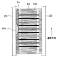
図2および図3に、コルゲートフィン10の拡大図を示す。コルゲートフィン10は、板状部材100が所定間隔で折り曲げられた構成である。コルゲートフィン10は、複数の折曲部12およびフィン本体部13を有している。複数の折曲部12は、コルゲートフィン10を構成する板状部材100が所定間隔で折り曲げられた部位である。フィン本体部13は、その折曲部12と折曲部12との間に配置される部位である。フィン本体部13には、板状部材100の一部が切り起こされた複数のルーバー14が設けられている。コルゲートフィン10のチューブ20側の外壁と、チューブ20の外壁とは、ろう付けにより接合されている。
コルゲートフィン10の表面には、親水性を高めるための複数の微細な溝部11が設けられている。具体的には、板状部材100の両面に複数の微細な溝部11が設けられている。複数の溝部11は、溝部11同士が所定の間隔をあけて並ぶように設けられている。なお、本実施形態で参照する各図面では、説明のため、コルゲートフィン10の表面に設けられる複数の溝部11を模式的に大きく示している。このことは、後述する第2~第6実施形態で参照する図面においても同様である。
複数の溝部11は、コルゲートフィン10の折曲部12およびフィン本体部13に設けられている。また、複数の溝部11は、ルーバー14にも設けられている。本実施形態では、複数の溝部11は、板状を成すフィン本体部13において、一方のチューブ20に接合された折曲部12から他方のチューブ20に接合された折曲部12に向かって延びるように形成されている。
溝部11の幅は、10~50μmが好ましい。溝部11の深さは、10μm以上が好ましい。溝部11のピッチは、50~200μmが好ましい。これにより、コルゲートフィン10の表面の親水性を高くすることが可能である。コルゲートフィン10の表面の親水性が高くなると、コルゲートフィン10の排水性が向上し、コルゲートフィン10の表面に凝縮水が滞留することが抑制される。したがって、凝縮水の滞留により空気通路の通風抵抗が大きくなることが抑制されるので、熱交換器1は熱交換性能を高めることができる。
本実施形態のコルゲートフィン10には、図3~図5に示すように、2つのチューブ20と接合される2つの折曲部12の間の複数の溝部11の途中に2つの隆起部111が形成されている。2つの隆起部111は、コルゲートフィン10の表面10aまで隆起している。これらの隆起部111により2つのチューブ20と接合される2つの折曲部12の間の複数の溝部11は2箇所で分断されている。
図21に示したように、複数の溝部11の途中に本実施形態のような隆起部111が形成されていない構成では、凝縮水Wcの量が多い場合、チューブ20側で発生した凝縮水Wcは図6中の矢印FL1に示すように上方から下方へと流れる。また、コルゲートフィン10の2つのチューブ20の間の中央部の方にある凝縮水は複数の溝部11により図6中の矢印FL3に示すようにチューブ20側へと進水する。
しかし、凝縮水Wcの量が少ない場合、図7中の矢印FL2に示すように複数の溝部11により、チューブ20側で発生した凝縮水Wcがコルゲートフィン10の2つのチューブ20の間の中央部の方まで進水してしまう。このため、かえって排水性が低下してしまう。
これに対し、本実施形態のコルゲートフィン10は、図9に示すように、2つのチューブ20と接合される2つの折曲部12の間の複数の溝部11の途中に隆起部111が形成されている。
したがって、凝縮水Wcの量が少ない場合、図8~図9に示すように、チューブ20側で発生した凝縮水Wcがコルゲートフィン10の2つのチューブ20の間の中央部の方まで流れ込むのを抑制することができる。すなわち、複数の溝部11の途中に形成された隆起部111によりチューブ20側で発生した凝縮水Wcがコルゲートフィン10の2つのチューブ20の間の中央部の方まで進水するのが抑制される。
また、凝縮水Wcの量が多い場合、図10~図11に示すように、複数の溝部11のうち隆起部111が形成されている部位に凝縮水Wcが溜まると、図10の矢印FL4に示すように、この凝縮水Wcによって隆起部111の両端部の凝縮水Wcが繋がる。したがって、コルゲートフィン10の2つのチューブ20の間の中央部に溜まった凝縮水Wcは、隆起部111が形成されている部位を超えて図10中の矢印FL1に示すように下方へと流れる。このため、排水性を確保することもできる。
以上、説明したように、本実施形態の熱交換器1は、第1の流体が流れる複数のチューブ20を備えている。また、熱交換器1は、チューブ20の内側を流れる第1の流体とチューブの外側を流れる第2の流体との熱交換効率を高めるコルゲートフィン10を備えている。また、コルゲートフィン10は、チューブ20に接合された複数の折曲部12を備えている。また、コルゲートフィン10は、隣り合う一方のチューブ20に接合された折曲部12と隣り合う他方のチューブ20に接合された折曲部12との間に配置されたフィン本体部13を有している。また、フィン本体部13の表面には、一方のチューブ20に接合された折曲部12から他方のチューブ20に接合された折曲部12に向かって延びる複数の溝部11が形成されている。そして、一方のチューブ20に接合された折曲部12と他方のチューブ20に接合された折曲部12との間の複数の溝部11の途中には、隆起部111が形成されている。なお、隆起部111は、溝部11の底部110からコルゲートフィン10の表面10aに向かって隆起する。
上記したように、一方のチューブ20に接合された折曲部12と他方のチューブ20に接合された折曲部12との間の複数の溝部11の途中には、該溝部11の底部110からコルゲートフィン10の表面10aに向かって隆起する隆起部111が形成されている。したがって、チューブ20からの凝縮水の流量が少ない場合にチューブ20からの凝縮水がコルゲートフィン10における隣り合うチューブ20の間の中央部の方まで流れ込むのを抑制することができる。
また、隆起部111は、溝部11の底部110からコルゲートフィン10の表面10aまで隆起している。これにより、隆起部111が形成された領域の親水性が大きく低下するので、より効果的にチューブ20からの凝縮水がコルゲートフィン10における隣り合うチューブ20の間の中央部の方まで流れ込むのを抑制することができる。
また、熱交換器1は、一方のチューブ20に接合された折曲部12と他方のチューブ20に接合された折曲部12との間の複数の溝部11の途中に隆起部111を少なくとも2つ備えている。
したがって、隣り合う両側のチューブ20からの凝縮水がコルゲートフィン10における隣り合うチューブ20の間の中央部の方まで流れ込むのを抑制することができる。
(第2実施形態)
第2実施形態に係る熱交換器1について図12を用いて説明する。上記第1実施形態の隆起部111は、溝部11の底部110からコルゲートフィン10の表面10aまで隆起している。これに対し、本実施形態の熱交換器1は、図12に示すように、隆起部111が、溝部11の底部110からコルゲートフィン10の表面10aよりも低い位置まで隆起している。
第2実施形態に係る熱交換器1について図12を用いて説明する。上記第1実施形態の隆起部111は、溝部11の底部110からコルゲートフィン10の表面10aまで隆起している。これに対し、本実施形態の熱交換器1は、図12に示すように、隆起部111が、溝部11の底部110からコルゲートフィン10の表面10aよりも低い位置まで隆起している。
このように、隆起部111が、溝部11の底部110からコルゲートフィン10の表面10aまで隆起していなくても、チューブ20側で発生した凝縮水Wcがコルゲートフィン10の2つのチューブ20の間の中央部の方まで進水するのを抑制することが可能である。
本実施形態では、上記第1実施形態と共通の構成から奏される同様の効果を上記第1実施形態と同様に得ることができる。
(第3実施形態)
第3実施形態に係る熱交換器1について図13を用いて説明する。本実施形態の熱交換器1は、複数の溝部11の途中に、溝幅が狭い狭幅部112が形成されている。
第3実施形態に係る熱交換器1について図13を用いて説明する。本実施形態の熱交換器1は、複数の溝部11の途中に、溝幅が狭い狭幅部112が形成されている。
一方のチューブ20に接合された折曲部12と他方のチューブ20に接合された折曲部12との間の複数の溝部11は、所定長の溝幅を有している。
また、一方のチューブ20に接合された折曲部12と他方のチューブ20に接合された折曲部12との間の複数の溝部11の途中には、所定長よりも溝幅の狭い狭幅部112が形成されている。
したがって、凝縮水Wcの量が少ない場合、狭幅部112によって、チューブ20側で発生した凝縮水がコルゲートフィン10の2つのチューブ20の間の中央部の方まで流れ込むのが抑制される。すなわち、複数の溝部11の途中に形成された狭幅部112によりチューブ20側で発生した凝縮水がコルゲートフィン10の2つのチューブ20の間の中央部の方まで進水するのが抑制される。
以上、説明したように、本実施形態の熱交換器1は、第1の流体が流れる複数のチューブ20を備えている。また、熱交換器1は、チューブ20の内側を流れる第1の流体とチューブの外側を流れる第2の流体との熱交換効率を高めるコルゲートフィン10を備えている。また、コルゲートフィン10は、チューブ20に接合された複数の折曲部12を備えている。また、コルゲートフィン10は、隣り合う一方のチューブ20に接合された折曲部12と隣り合う他方のチューブ20に接合された折曲部12との間に配置されたフィン本体部13を有している。また、フィン本体部13には、隣り合う一方のチューブ20に接合された折曲部12から隣り合う他方のチューブ20に接合された折曲部12に向かって延びる複数の溝部11が形成されている。また、一方のチューブ20に接合された折曲部12と他方のチューブ20に接合された折曲部12との間の複数の溝部11は、所定長の溝幅を有している。そして、一方のチューブ20に接合された折曲部12と他方のチューブ20に接合された折曲部12との間の溝部11の途中には、所定長よりも溝幅の狭幅部112が形成されている。
上記した構成によれば、一方のチューブ20に接合された折曲部12と他方のチューブ20に接合された折曲部12との間の複数の溝部11の途中には、所定長よりも溝幅の狭い狭幅部112が形成されている。したがって、チューブ20からの凝縮水の流量が少ない場合にチューブ20からの凝縮水がコルゲートフィン10における隣り合うチューブ20の間の中央部の方まで流れ込むのを抑制することができる。
また、凝縮水の量が多い場合、複数の溝部11のうち狭幅部112が形成されている部位に凝縮水が溜まるとこの凝縮水によって狭幅部112の両端部の凝縮水が繋がる。したがって、コルゲートフィン10の2つのチューブ20の間の中央部に溜まった凝縮水は、狭幅部112が形成されている部位を超えて下方へと流れる。このため、排水性を確保することもできる。
また、熱交換器1は、一方のチューブ20に接合された折曲部12と他方のチューブ20に接合された折曲部12との間の複数の溝部11の途中に狭幅部112を2つ備えている。
したがって、隣り合う両側のチューブ20からの凝縮水がコルゲートフィン10における隣り合うチューブ20の間の中央部の方まで流れ込むのを抑制することができる。
(第4実施形態)
第4実施形態に係る熱交換器1について図14を用いて説明する。本実施形態の熱交換器1は、上記第1実施形態の熱交換器1に対して、複数の溝部11のうち、一部の溝部11に隆起部111が形成されていない点が異なる。
第4実施形態に係る熱交換器1について図14を用いて説明する。本実施形態の熱交換器1は、上記第1実施形態の熱交換器1に対して、複数の溝部11のうち、一部の溝部11に隆起部111が形成されていない点が異なる。
このように、複数の溝部11のうち一部の溝部11に隆起部111を形成しないようにすることもできる。
本実施形態では、上記第1実施形態と共通の構成から奏される同様の効果を上記第1実施形態と同様に得ることができる。
(第5実施形態)
第5実施形態に係る熱交換器1について図15を用いて説明する。本実施形態の熱交換器1は、隣り合う一方のチューブ20に接合された折曲部12と他方のチューブ20に接合された折曲部12との間の隣り合う複数の溝部11の途中に、集合部113aと分岐部113bが形成されている。集合部113aは、複数の溝部11を集合させ、分岐部113bは、集合部113aに接続されて複数の溝部に分岐する。また、集合部113aと分岐部113bとの間にコルゲートフィン10の表面の親水性を複数の溝部11が形成された部位よりも低減させる親水性低減部113が形成されている。
第5実施形態に係る熱交換器1について図15を用いて説明する。本実施形態の熱交換器1は、隣り合う一方のチューブ20に接合された折曲部12と他方のチューブ20に接合された折曲部12との間の隣り合う複数の溝部11の途中に、集合部113aと分岐部113bが形成されている。集合部113aは、複数の溝部11を集合させ、分岐部113bは、集合部113aに接続されて複数の溝部に分岐する。また、集合部113aと分岐部113bとの間にコルゲートフィン10の表面の親水性を複数の溝部11が形成された部位よりも低減させる親水性低減部113が形成されている。
したがって、親水性低減部113により、チューブ20からの凝縮水の流量が少ない場合にチューブ20からの凝縮水がコルゲートフィン10における隣り合うチューブ20の間の中央部の方まで流れ込むのを抑制することができる。
また、一方のチューブ20に接合された折曲部12と他方のチューブ20に接合された折曲部12との間の複数の溝部11の途中に親水性低減部113が2つ形成されている。
以上、説明したように、本実施形態の熱交換器1は、第1の流体が流れる複数のチューブ20を備えている。また、熱交換器1は、チューブ20の内側を流れる第1の流体とチューブ20の外側を流れる第2の流体との熱交換効率を高めるコルゲートフィン10を備えている。また、コルゲートフィン10は、チューブ20に接合された複数の折曲部12と、隣り合う一方のチューブ20に接合された折曲部12と隣り合う他方のチューブ20に接合された折曲部12との間に配置されたフィン本体部13と、を有している。また、フィン本体部13の表面には、一方のチューブ20に接合された折曲部12から他方のチューブ20に接合された折曲部12に向かって延びる複数の溝部11が形成されている。また、一方のチューブ20に接合された折曲部12と他方のチューブ20に接合された折曲部12との間の隣り合う複数の溝部11の途中には、複数の溝部11を集合させる集合部113aが形成されている。また、一方のチューブ20に接合された折曲部12と他方のチューブに接合された折曲部12との間の隣り合う複数の溝部11の途中には、集合部113aに接続されて複数の溝部に分岐する分岐部113bが形成されている。そして、集合部113aと分岐部113bとの間にコルゲートフィン10の表面の親水性を複数の溝部11が形成された部位よりも低減させる親水性低減部113が形成されている。
上記した構成によれば、一方のチューブ20に接合された折曲部12と他方のチューブ20に接合された折曲部12との間の隣り合う2つの溝部11の途中に集合部113aと分岐部113bが形成されている。
そして、集合部113aと分岐部113bとの間にコルゲートフィン10の表面の親水性を2つの溝部11が形成された部位よりも低減させる親水性低減部113が形成されている。したがって、チューブ20からの凝縮水の流量が少ない場合にチューブ20からの凝縮水がコルゲートフィン10における隣り合うチューブ20の間の中央部の方まで流れ込むのを抑制することができる。
また、熱交換器1は、一方のチューブ20に接合された折曲部12と他方のチューブ20に接合された折曲部12との間の複数の溝部11の途中に親水性低減部113を2つ備えている。
したがって、隣り合う両側のチューブ20からの凝縮水がコルゲートフィン10における隣り合うチューブ20の間の中央部の方まで流れ込むのを抑制することができる。
(第6実施形態)
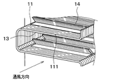
第6実施形態に係る熱交換器1について図16~図20を用いて説明する。本実施形態の熱交換器1を図16に示す。また、図17~図20は、図2中のXVII方向からフィン本体部13およびチューブ20を見た図である。また、図17~図20は、2つのチューブ20の間にルーバー14が切起こされる前の板状部材100が配置された状態として示してある。なお、図17~図20には、ルーバー14が切起こされる前の溝140が示されている。
第6実施形態に係る熱交換器1について図16~図20を用いて説明する。本実施形態の熱交換器1を図16に示す。また、図17~図20は、図2中のXVII方向からフィン本体部13およびチューブ20を見た図である。また、図17~図20は、2つのチューブ20の間にルーバー14が切起こされる前の板状部材100が配置された状態として示してある。なお、図17~図20には、ルーバー14が切起こされる前の溝140が示されている。
図16に示すように、熱交換器1は、溝部11が延びる方向とフィン本体部13の表面に沿って直交する方向に進むにつれて、隆起部111が形成された領域が隣り合う一方のチューブ20から隣り合う他方のチューブ20に近づくように形成されている。すなわち、熱交換器1は、図17に示すように、隆起部111が形成された領域が、隣り合うチューブ20の間に斜めに形成されている。
図18中に示される通風方向に空気が流れると、熱交換器1は、チューブ20からの凝縮水が、隆起部111が形成された領域で堰き止められ、領域Arに溜まり、ルーバー14の隙間から速やかに下方へ流下する。したがって、凝縮水が溜まる領域Arが比較的小さく、良好な排水性を得ることができる。
図19は、溝部11が延びる方向とフィン本体部13の表面に沿って直交する方向に隆起部111が形成された領域が延びるように形成された比較例を表している。
図19に示すような構成では、図19中に示される通風方向に空気が流れると、チューブ20からの凝縮水は比較的面積の大きな領域Arに溜まる。したがって、良好な排水性を得ることはできない。
本実施形態では、溝部11が延びる方向とフィン本体部13の表面に沿って直交する方向に進むにつれて隆起部111が形成された領域を、隣り合う一方のチューブ20から隣り合う他方のチューブ20に近づくように形成した。
これに対し、溝部11が延びる方向とフィン本体部13の表面に沿って直交する方向に進むにつれて狭幅部112あるいは親水性低減部113が形成された領域を、隣り合う一方のチューブ20から隣り合う他方のチューブ20に近づくように形成してもよい。
(他の実施形態)
(1)上記各実施形態では、隆起部111、狭幅部112あるいは親水性低減部113を複数の溝部11の途中に2つ形成した。しかし、隆起部111、狭幅部112、親水性低減部113の数は2つに限定されるものではない。
(1)上記各実施形態では、隆起部111、狭幅部112あるいは親水性低減部113を複数の溝部11の途中に2つ形成した。しかし、隆起部111、狭幅部112、親水性低減部113の数は2つに限定されるものではない。
(2)上記第3実施形態では、複数の溝部11の途中に溝部11の幅よりも幅の狭い狭幅部112を形成した。これに対し、複数の溝部11の途中に溝部11の幅がなくなる部位を形成し、この部位によって複数の溝部11を3つに分断するようにしてもよい。
なお、本開示は上記した実施形態に限定されるものではなく、本開示に記載した範囲内において適宜変更が可能である。また、上記各実施形態は、互いに無関係なものではなく、組み合わせが明らかに不可な場合を除き、適宜組み合わせが可能である。また、上記各実施形態において、実施形態を構成する要素は、特に必須であると明示した場合および原理的に明らかに必須であると考えられる場合等を除き、必ずしも必須のものではないことは言うまでもない。また、上記各実施形態において、実施形態の構成要素の個数、数値、量、範囲等の数値が言及されている場合、特に必須であると明示した場合および原理的に明らかに特定の数に限定される場合等を除き、その特定の数に限定されるものではない。また、上記各実施形態において、構成要素等の材質、形状、位置関係等に言及するときは、特に明示した場合および原理的に特定の材質、形状、位置関係等に限定される場合等を除き、その材質、形状、位置関係等に限定されるものではない。
(まとめ)
上記各実施形態の一部または全部で示された第1の観点によれば、熱交換器は、第1の流体が流れる複数のチューブを備えてる。また、熱交換器は、チューブの内側を流れる第1の流体とチューブの外側を流れる第2の流体との熱交換効率を高めるコルゲートフィンを備えている。また、コルゲートフィンは、チューブに接合された複数の折曲部を有している。また、コルゲートフィンは、隣り合う一方のチューブに接合された折曲部と隣り合う他方のチューブに接合された折曲部との間に配置されたフィン本体部を有している。また、フィン本体部の表面には、一方のチューブに接合された折曲部から他方のチューブに接合された折曲部に向かって延びる複数の溝部が形成されている。また、一方のチューブに接合された折曲部と他方のチューブに接合された折曲部との間の複数の溝部の少なくとも1つの溝部の途中には、隆起部が形成されている。なお、隆起部は、溝部の底部からコルゲートフィンの表面に向かって隆起する。
上記各実施形態の一部または全部で示された第1の観点によれば、熱交換器は、第1の流体が流れる複数のチューブを備えてる。また、熱交換器は、チューブの内側を流れる第1の流体とチューブの外側を流れる第2の流体との熱交換効率を高めるコルゲートフィンを備えている。また、コルゲートフィンは、チューブに接合された複数の折曲部を有している。また、コルゲートフィンは、隣り合う一方のチューブに接合された折曲部と隣り合う他方のチューブに接合された折曲部との間に配置されたフィン本体部を有している。また、フィン本体部の表面には、一方のチューブに接合された折曲部から他方のチューブに接合された折曲部に向かって延びる複数の溝部が形成されている。また、一方のチューブに接合された折曲部と他方のチューブに接合された折曲部との間の複数の溝部の少なくとも1つの溝部の途中には、隆起部が形成されている。なお、隆起部は、溝部の底部からコルゲートフィンの表面に向かって隆起する。
また、第2の観点によれば、隆起部は、溝部の底部からコルゲートフィンの表面まで隆起している。これにより、隆起部が形成された領域の親水性が大きく低下するので、より効果的にチューブからの凝縮水がコルゲートフィンにおける隣り合うチューブの間の中央部の方まで流れ込むのを抑制することができる。
また、第3の観点によれば、熱交換器は、一方のチューブに接合された折曲部と他方のチューブに接合された折曲部との間の複数の溝部の途中に隆起部を少なくとも2つ備えている。
したがって、隣り合う両側のチューブからの凝縮水がコルゲートフィンにおける隣り合うチューブの間の中央部の方まで流れ込むのを抑制することができる。
また、第4の観点によれば、フィン本体部には、該フィン本体部の一部が切り起こされたルーバーが形成されている。フィン本体部は、溝部が延びる方向とフィン本体部の表面に沿って直交する方向に進むにつれて隆起部が形成された領域が一方のチューブから他方のチューブに近づくように形成されている。
したがって、溝部が延びる方向とフィン本体部の表面に沿って直交する方向に空気が流れた場合にチューブからの凝縮水が、隆起部が形成された領域で堰き止められルーバーが形成された部位から速やかに下方に流下するので、排水性を向上することができる。
また、第5の観点によれば、熱交換器は、第1の流体が流れる複数のチューブを備えている。また、熱交換器は、チューブの内側を流れる第1の流体とチューブの外側を流れる第2の流体との熱交換効率を高めるコルゲートフィンを備えている。また、コルゲートフィンは、チューブに接合された複数の折曲部を有している。また、コルゲートフィンは、隣り合う一方のチューブに接合された折曲部と隣り合う他方のチューブに接合された折曲部との間に配置されたフィン本体部を有している。また、フィン本体部には、隣り合う一方のチューブに接合された折曲部から隣り合う他方のチューブに接合された折曲部に向かって延びる複数の溝部が形成されている。また、一方のチューブに接合された折曲部と他方のチューブに接合された折曲部との間の複数の溝部は、所定長の溝幅を有している。また、一方のチューブに接合された折曲部と他方のチューブに接合された折曲部との間の複数の溝部の少なくとも1つの溝部の途中には、所定長よりも溝幅の狭い狭幅部が形成されている。
また、第6の観点によれば、熱交換器は、一方のチューブに接合された折曲部と他方のチューブに接合された折曲部との間の複数の溝部の途中に狭幅部を少なくとも2つ備えている。
したがって、隣り合う両側のチューブからの凝縮水がコルゲートフィンにおける隣り合うチューブの間の中央部の方まで流れ込むのを抑制することができる。
また、第7の観点によれば、フィン本体部には、該フィン本体部の一部が切り起こされた複数のルーバーが形成されている。また、溝部が延びる方向とフィン本体部の表面に沿って直交する方向に進むにつれて狭幅部が形成された領域が一方のチューブから他方のチューブに近づくように形成されている。
したがって、溝部が延びる方向とフィン本体部の表面に沿って直交する方向に空気が流れた場合にチューブからの凝縮水が、狭幅部が形成された領域で堰き止められルーバーが形成された部位から速やかに下方に流下するので、排水性を向上することができる。
また、第8の観点によれば、熱交換器は、第1の流体が流れる複数のチューブを備えている。また、熱交換器は、チューブの内側を流れる第1の流体とチューブの外側を流れる第2の流体との熱交換効率を高めるコルゲートフィンを備えている。また、コルゲートフィンは、チューブに接合された複数の折曲部を有している。また、コルゲートフィンは、隣り合う一方のチューブに接合された折曲部と隣り合う他方のチューブに接合された折曲部との間に配置されたフィン本体部を有している。また、フィン本体部の表面には、一方のチューブに接合された折曲部から他方のチューブに接合された折曲部に向かって延びる複数の溝部が形成されている。また、一方のチューブに接合された折曲部と他方のチューブに接合された折曲部との間の隣り合う少なくとも2つの溝部の途中には、集合部と分岐部が形成されている。集合部と分岐部は、隣り合う少なくとも2つの溝部を集合させ、分岐部は、集合部に接続されて複数の溝部に分岐する。また、集合部と分岐部との間にコルゲートフィンの表面の親水性を少なくとも2つの溝部が形成された部位よりも低減させる親水性低減部が形成されている。
また、第9の観点によれば、熱交換器は、一方のチューブに接合された折曲部と他方のチューブに接合された折曲部との間の複数の溝部の途中に親水性低減部を少なくとも2つ備えている。
したがって、隣り合う両側のチューブからの凝縮水がコルゲートフィンにおける隣り合うチューブの間の中央部の方まで流れ込むのを抑制することができる。
また、第10の観点によれば、フィン本体部には、該フィン本体部の一部が切り起こされた複数のルーバーが形成されている。また、溝部が延びる方向とフィン本体部の表面に沿って直交する方向に進むにつれて親水性低減部が形成された領域が一方のチューブから他方のチューブに近づくように形成されている。
したがって、溝部が延びる方向とフィン本体部の表面に沿って直交する方向に空気が流れた場合にチューブからの凝縮水が、親水性低減部が形成された領域で堰き止められルーバーが形成された部位から速やかに下方に流下するので、排水性を向上することができる。
Claims (10)
- 熱交換器であって、
第1の流体が流れる複数のチューブ(20)と、
前記チューブの内側を流れる前記第1の流体と前記チューブの外側を流れる第2の流体との熱交換効率を高めるコルゲートフィン(10)と、を備え、
前記コルゲートフィンは、前記チューブに接合された複数の折曲部(12)と、隣り合う一方の前記チューブに接合された前記折曲部と隣り合う他方の前記チューブに接合された前記折曲部との間に配置されたフィン本体部(13)と、を有し、
前記フィン本体部の表面には、一方の前記チューブに接合された前記折曲部から他方の前記チューブに接合された前記折曲部に向かって延びる複数の溝部(11)が形成され、
一方の前記チューブに接合された前記折曲部と他方の前記チューブに接合された前記折曲部との間の前記複数の溝部の少なくとも1つの前記溝部の途中には、該溝部の底部(110)から前記コルゲートフィンの表面(10a)に向かって隆起する隆起部(111)が形成されている熱交換器。 - 前記隆起部は、前記溝部の底部から前記コルゲートフィンの表面まで隆起している請求項1に記載の熱交換器。
- 一方の前記チューブに接合された前記折曲部と他方の前記チューブに接合された前記折曲部との間の前記複数の溝部の途中に前記隆起部を少なくとも2つ備えた請求項1または2に記載の熱交換器。
- 前記フィン本体部には、該フィン本体部の一部が切り起こされた複数のルーバー(14)が形成されており、
前記溝部が延びる方向と前記フィン本体部の表面に沿って直交する方向に進むにつれて前記隆起部が形成された領域が一方の前記チューブから他方の前記チューブに近づくように形成されている請求項1ないし3のいずれか1つに記載の熱交換器。 - 熱交換器であって、
第1の流体が流れる複数のチューブ(20)と、
前記チューブの内側を流れる前記第1の流体と前記チューブの外側を流れる第2の流体との熱交換効率を高めるコルゲートフィン(10)と、を備え、
前記コルゲートフィンは、前記チューブに接合された複数の折曲部(12)と、隣り合う一方の前記チューブに接合された前記折曲部と隣り合う他方の前記チューブに接合された前記折曲部との間に配置されたフィン本体部(13)と、を有し、
前記フィン本体部には、隣り合う一方の前記チューブに接合された前記折曲部から隣り合う他方の前記チューブに接合された前記折曲部に向かって延びる複数の溝部(11)が形成され、
一方の前記チューブに接合された前記折曲部と他方の前記チューブに接合された前記折曲部との間の前記複数の溝部は、所定長の溝幅を有し、
一方の前記チューブに接合された前記折曲部と他方の前記チューブに接合された前記折曲部との間の前記複数の溝部の少なくとも1つの前記溝部の途中には、前記所定長よりも溝幅の狭い狭幅部(112)が形成されている熱交換器。 - 一方の前記チューブに接合された前記折曲部と他方の前記チューブに接合された前記折曲部との間の前記複数の溝部の途中に前記狭幅部を少なくとも2つ備えた請求項5に記載の熱交換器。
- 前記フィン本体部には、該フィン本体部の一部が切り起こされた複数のルーバー(14)が形成されており、
前記溝部が延びる方向と前記フィン本体部の表面に沿って直交する方向に進むにつれて前記狭幅部が形成された領域が一方の前記チューブから他方の前記チューブに近づくように形成されている請求項6に記載の熱交換器。 - 熱交換器であって、
第1の流体が流れる複数のチューブ(20)と、
前記チューブの内側を流れる前記第1の流体と前記チューブの外側を流れる第2の流体との熱交換効率を高めるコルゲートフィン(10)と、を備え、
前記コルゲートフィンは、前記チューブに接合された複数の折曲部(12)と、隣り合う一方の前記チューブに接合された前記折曲部と隣り合う他方の前記チューブに接合された前記折曲部との間に配置されたフィン本体部(13)と、を有し、
前記フィン本体部の表面には、一方の前記チューブに接合された前記折曲部から他方の前記チューブに接合された前記折曲部に向かって延びる複数の溝部(11)が形成され、
一方の前記チューブに接合された前記折曲部と他方の前記チューブに接合された前記折曲部との間の隣り合う少なくとも2つの前記溝部の途中には、隣り合う少なくとも2つの前記溝部を集合させる集合部(113a)と、前記集合部に接続されて前記複数の溝部に分岐する分岐部(113b)と、が形成され、
前記集合部と前記分岐部との間に前記コルゲートフィンの表面の親水性を前記少なくとも2つの前記溝部が形成された部位よりも低減させる親水性低減部(113)が形成されている熱交換器。 - 一方の前記チューブに接合された前記折曲部と他方の前記チューブに接合された前記折曲部との間の前記複数の溝部の途中に前記親水性低減部を少なくとも2つ備えた請求項8に記載の熱交換器。
- 前記フィン本体部には、該フィン本体部の一部が切り起こされた複数のルーバー(14)が形成されており、
前記溝部が延びる方向と前記フィン本体部の表面に沿って直交する方向に進むにつれて前記親水性低減部が形成された領域が一方の前記チューブから他方の前記チューブに近づくように形成されている請求項8または9に記載の熱交換器。
Priority Applications (3)
| Application Number | Priority Date | Filing Date | Title |
|---|---|---|---|
| DE112020003723.1T DE112020003723T5 (de) | 2019-08-06 | 2020-07-31 | Wärmetauscher |
| CN202080055610.5A CN114207374B (zh) | 2019-08-06 | 2020-07-31 | 热交换器 |
| US17/592,680 US12092403B2 (en) | 2019-08-06 | 2022-02-04 | Heat exchanger |
Applications Claiming Priority (2)
| Application Number | Priority Date | Filing Date | Title |
|---|---|---|---|
| JP2019-144656 | 2019-08-06 | ||
| JP2019144656A JP7263970B2 (ja) | 2019-08-06 | 2019-08-06 | 熱交換器 |
Related Child Applications (1)
| Application Number | Title | Priority Date | Filing Date |
|---|---|---|---|
| US17/592,680 Continuation US12092403B2 (en) | 2019-08-06 | 2022-02-04 | Heat exchanger |
Publications (1)
| Publication Number | Publication Date |
|---|---|
| WO2021024958A1 true WO2021024958A1 (ja) | 2021-02-11 |
Family
ID=74503822
Family Applications (1)
| Application Number | Title | Priority Date | Filing Date |
|---|---|---|---|
| PCT/JP2020/029541 WO2021024958A1 (ja) | 2019-08-06 | 2020-07-31 | 熱交換器 |
Country Status (5)
| Country | Link |
|---|---|
| US (1) | US12092403B2 (ja) |
| JP (1) | JP7263970B2 (ja) |
| CN (1) | CN114207374B (ja) |
| DE (1) | DE112020003723T5 (ja) |
| WO (1) | WO2021024958A1 (ja) |
Citations (4)
| Publication number | Priority date | Publication date | Assignee | Title |
|---|---|---|---|---|
| JP2000241093A (ja) * | 1999-02-24 | 2000-09-08 | Daikin Ind Ltd | 空気熱交換器 |
| JP2013190169A (ja) * | 2012-03-14 | 2013-09-26 | Sharp Corp | 熱交換器 |
| WO2018230431A1 (ja) * | 2017-06-12 | 2018-12-20 | 株式会社デンソー | 熱交換器およびコルゲートフィン |
| WO2018230430A1 (ja) * | 2017-06-12 | 2018-12-20 | 株式会社デンソー | 熱交換器及びコルゲートフィン |
Family Cites Families (25)
| Publication number | Priority date | Publication date | Assignee | Title |
|---|---|---|---|---|
| JPS59109418A (ja) | 1982-12-15 | 1984-06-25 | Nippon Denso Co Ltd | 自動車用空調装置の内外気切換装置 |
| EP0469150A4 (en) * | 1990-02-20 | 1993-03-31 | Nauchno-Proidsvodstevennoe Obiedinenie Po Traktorostroeniju | Package of plates for tube-plate heat exchanger with diffuser-confuser channels and a rotor die for making the plates of said package |
| JP2003336988A (ja) * | 2002-05-20 | 2003-11-28 | Japan Climate Systems Corp | 熱交換器 |
| JP2004060934A (ja) * | 2002-07-25 | 2004-02-26 | Toyo Radiator Co Ltd | 蒸発器 |
| CN1566889A (zh) * | 2003-06-17 | 2005-01-19 | 乐金电子(天津)电器有限公司 | 热交换器的冷凝水排出装置 |
| US6889759B2 (en) * | 2003-06-25 | 2005-05-10 | Evapco, Inc. | Fin for heat exchanger coil assembly |
| WO2006041206A1 (en) * | 2004-10-13 | 2006-04-20 | Showa Denko K.K. | Evaporator |
| US7475719B2 (en) * | 2006-12-14 | 2009-01-13 | Evapco, Inc. | High-frequency, low-amplitude corrugated fin for a heat exchanger coil assembly |
| JP5417718B2 (ja) * | 2007-03-07 | 2014-02-19 | ダイキン工業株式会社 | 熱交換器 |
| CN101598514A (zh) * | 2008-06-06 | 2009-12-09 | 三花丹佛斯(杭州)微通道换热器有限公司 | 热交换器及其散热管 |
| JP2010025477A (ja) | 2008-07-22 | 2010-02-04 | Daikin Ind Ltd | 熱交換器 |
| KR20100110036A (ko) * | 2009-04-02 | 2010-10-12 | 엘지전자 주식회사 | 열교환기 및 그 제조방법 |
| JP5156773B2 (ja) * | 2010-02-25 | 2013-03-06 | 株式会社小松製作所 | コルゲートフィンおよびそれを備える熱交換器 |
| CN102235735B (zh) * | 2010-05-05 | 2013-12-04 | 约克(无锡)空调冷冻设备有限公司 | 用于热泵系统的换热器 |
| CN202057209U (zh) * | 2011-04-15 | 2011-11-30 | 江苏宝得换热设备有限公司 | 一种换热器 |
| JP2013245883A (ja) | 2012-05-28 | 2013-12-09 | Panasonic Corp | フィンチューブ熱交換器 |
| EP2918958B1 (en) * | 2012-10-16 | 2018-12-05 | Mitsubishi Electric Corporation | Plate heat exchanger and refrigeration cycle device provided with plate heat exchanger |
| JP6225042B2 (ja) * | 2014-02-14 | 2017-11-01 | 住友精密工業株式会社 | プレートフィン熱交換器、及び、熱交換器用コルゲートフィンの製造方法 |
| CN105987540A (zh) * | 2015-02-10 | 2016-10-05 | 上海交通大学 | 管片式平行流换热器 |
| CN104964487B (zh) * | 2015-05-18 | 2017-12-19 | 广东美的制冷设备有限公司 | 热交换器、空调器及金属箔的加工方法 |
| JP6911549B2 (ja) | 2017-06-12 | 2021-07-28 | 株式会社デンソー | 熱交換器及びコルゲートフィン |
| JP6747384B2 (ja) | 2017-06-12 | 2020-08-26 | 株式会社デンソー | 熱交換器およびコルゲートフィン |
| CN109539852A (zh) * | 2017-09-22 | 2019-03-29 | 浙江盾安机械有限公司 | 一种微通道换热器的扁管以及微通道换热器 |
| JP6839673B2 (ja) | 2018-02-16 | 2021-03-10 | 日本電信電話株式会社 | アプリケーション分割装置、方法およびプログラム |
| JP7188128B2 (ja) | 2018-03-14 | 2022-12-13 | 株式会社デンソー | 熱交換器 |
-
2019
- 2019-08-06 JP JP2019144656A patent/JP7263970B2/ja active Active
-
2020
- 2020-07-31 WO PCT/JP2020/029541 patent/WO2021024958A1/ja active Application Filing
- 2020-07-31 DE DE112020003723.1T patent/DE112020003723T5/de active Pending
- 2020-07-31 CN CN202080055610.5A patent/CN114207374B/zh active Active
-
2022
- 2022-02-04 US US17/592,680 patent/US12092403B2/en active Active
Patent Citations (4)
| Publication number | Priority date | Publication date | Assignee | Title |
|---|---|---|---|---|
| JP2000241093A (ja) * | 1999-02-24 | 2000-09-08 | Daikin Ind Ltd | 空気熱交換器 |
| JP2013190169A (ja) * | 2012-03-14 | 2013-09-26 | Sharp Corp | 熱交換器 |
| WO2018230431A1 (ja) * | 2017-06-12 | 2018-12-20 | 株式会社デンソー | 熱交換器およびコルゲートフィン |
| WO2018230430A1 (ja) * | 2017-06-12 | 2018-12-20 | 株式会社デンソー | 熱交換器及びコルゲートフィン |
Also Published As
| Publication number | Publication date |
|---|---|
| DE112020003723T5 (de) | 2022-06-09 |
| JP7263970B2 (ja) | 2023-04-25 |
| CN114207374B (zh) | 2024-05-07 |
| US20220155028A1 (en) | 2022-05-19 |
| CN114207374A (zh) | 2022-03-18 |
| US12092403B2 (en) | 2024-09-17 |
| JP2021025717A (ja) | 2021-02-22 |
Similar Documents
| Publication | Publication Date | Title |
|---|---|---|
| US20120103583A1 (en) | Heat exchanger and fin for the same | |
| JP2007113802A (ja) | 蒸発器 | |
| JP2006322698A (ja) | 熱交換器 | |
| US20230003467A1 (en) | Heat exchanger and corrugated fin | |
| JP6120978B2 (ja) | 熱交換器及びそれを用いた空気調和機 | |
| JP2001324244A (ja) | 熱交換器 | |
| US7013952B2 (en) | Stack type heat exchanger | |
| JP7188128B2 (ja) | 熱交換器 | |
| JP6425829B2 (ja) | 熱交換器及び冷凍サイクル装置 | |
| JP6747384B2 (ja) | 熱交換器およびコルゲートフィン | |
| JP2006084078A (ja) | 細径多管式熱交換器の細径伝熱管ユニット | |
| JP6558268B2 (ja) | 冷媒蒸発器 | |
| JP2016148480A (ja) | 熱交換器 | |
| WO2021024958A1 (ja) | 熱交換器 | |
| JP2011112315A (ja) | フィンチューブ型熱交換器及びこれを用いた空気調和機 | |
| JP2010025482A (ja) | 熱交換器 | |
| JP7024522B2 (ja) | 熱交換器 | |
| JP6795012B2 (ja) | 熱交換器およびコルゲートフィン | |
| WO2020184198A1 (ja) | 熱交換器 | |
| JP7006376B2 (ja) | 熱交換器 | |
| WO2018008134A1 (ja) | 熱交換器 | |
| JP7164801B2 (ja) | 熱交換器 | |
| JP7100242B2 (ja) | 熱交換器 | |
| WO2019167839A1 (ja) | 熱交換器 | |
| JP6613996B2 (ja) | 冷媒蒸発器 |
Legal Events
| Date | Code | Title | Description |
|---|---|---|---|
| 121 | Ep: the epo has been informed by wipo that ep was designated in this application |
Ref document number: 20849281 Country of ref document: EP Kind code of ref document: A1 |
|
| 122 | Ep: pct application non-entry in european phase |
Ref document number: 20849281 Country of ref document: EP Kind code of ref document: A1 |