WO2021024756A1 - Connecteur - Google Patents
Connecteur Download PDFInfo
- Publication number
- WO2021024756A1 WO2021024756A1 PCT/JP2020/027815 JP2020027815W WO2021024756A1 WO 2021024756 A1 WO2021024756 A1 WO 2021024756A1 JP 2020027815 W JP2020027815 W JP 2020027815W WO 2021024756 A1 WO2021024756 A1 WO 2021024756A1
- Authority
- WO
- WIPO (PCT)
- Prior art keywords
- housing
- movable member
- lock function
- release
- female
- Prior art date
Links
Images


Classifications
-
- H—ELECTRICITY
- H01—ELECTRIC ELEMENTS
- H01R—ELECTRICALLY-CONDUCTIVE CONNECTIONS; STRUCTURAL ASSOCIATIONS OF A PLURALITY OF MUTUALLY-INSULATED ELECTRICAL CONNECTING ELEMENTS; COUPLING DEVICES; CURRENT COLLECTORS
- H01R13/00—Details of coupling devices of the kinds covered by groups H01R12/70 or H01R24/00 - H01R33/00
- H01R13/62—Means for facilitating engagement or disengagement of coupling parts or for holding them in engagement
- H01R13/639—Additional means for holding or locking coupling parts together, after engagement, e.g. separate keylock, retainer strap
-
- H—ELECTRICITY
- H01—ELECTRIC ELEMENTS
- H01R—ELECTRICALLY-CONDUCTIVE CONNECTIONS; STRUCTURAL ASSOCIATIONS OF A PLURALITY OF MUTUALLY-INSULATED ELECTRICAL CONNECTING ELEMENTS; COUPLING DEVICES; CURRENT COLLECTORS
- H01R13/00—Details of coupling devices of the kinds covered by groups H01R12/70 or H01R24/00 - H01R33/00
- H01R13/62—Means for facilitating engagement or disengagement of coupling parts or for holding them in engagement
- H01R13/629—Additional means for facilitating engagement or disengagement of coupling parts, e.g. aligning or guiding means, levers, gas pressure electrical locking indicators, manufacturing tolerances
- H01R13/633—Additional means for facilitating engagement or disengagement of coupling parts, e.g. aligning or guiding means, levers, gas pressure electrical locking indicators, manufacturing tolerances for disengagement only
-
- H—ELECTRICITY
- H01—ELECTRIC ELEMENTS
- H01R—ELECTRICALLY-CONDUCTIVE CONNECTIONS; STRUCTURAL ASSOCIATIONS OF A PLURALITY OF MUTUALLY-INSULATED ELECTRICAL CONNECTING ELEMENTS; COUPLING DEVICES; CURRENT COLLECTORS
- H01R13/00—Details of coupling devices of the kinds covered by groups H01R12/70 or H01R24/00 - H01R33/00
- H01R13/40—Securing contact members in or to a base or case; Insulating of contact members
- H01R13/42—Securing in a demountable manner
- H01R13/436—Securing a plurality of contact members by one locking piece or operation
- H01R13/4361—Insertion of locking piece perpendicular to direction of contact insertion
- H01R13/4362—Insertion of locking piece perpendicular to direction of contact insertion comprising a temporary and a final locking position
-
- H—ELECTRICITY
- H01—ELECTRIC ELEMENTS
- H01R—ELECTRICALLY-CONDUCTIVE CONNECTIONS; STRUCTURAL ASSOCIATIONS OF A PLURALITY OF MUTUALLY-INSULATED ELECTRICAL CONNECTING ELEMENTS; COUPLING DEVICES; CURRENT COLLECTORS
- H01R13/00—Details of coupling devices of the kinds covered by groups H01R12/70 or H01R24/00 - H01R33/00
- H01R13/40—Securing contact members in or to a base or case; Insulating of contact members
- H01R13/42—Securing in a demountable manner
- H01R13/426—Securing by a separate resilient retaining piece supported by base or case, e.g. collar or metal contact-retention clip
-
- H—ELECTRICITY
- H01—ELECTRIC ELEMENTS
- H01R—ELECTRICALLY-CONDUCTIVE CONNECTIONS; STRUCTURAL ASSOCIATIONS OF A PLURALITY OF MUTUALLY-INSULATED ELECTRICAL CONNECTING ELEMENTS; COUPLING DEVICES; CURRENT COLLECTORS
- H01R13/00—Details of coupling devices of the kinds covered by groups H01R12/70 or H01R24/00 - H01R33/00
- H01R13/46—Bases; Cases
-
- H—ELECTRICITY
- H01—ELECTRIC ELEMENTS
- H01R—ELECTRICALLY-CONDUCTIVE CONNECTIONS; STRUCTURAL ASSOCIATIONS OF A PLURALITY OF MUTUALLY-INSULATED ELECTRICAL CONNECTING ELEMENTS; COUPLING DEVICES; CURRENT COLLECTORS
- H01R13/00—Details of coupling devices of the kinds covered by groups H01R12/70 or H01R24/00 - H01R33/00
- H01R13/62—Means for facilitating engagement or disengagement of coupling parts or for holding them in engagement
- H01R13/627—Snap or like fastening
- H01R13/6271—Latching means integral with the housing
- H01R13/6272—Latching means integral with the housing comprising a single latching arm
-
- H—ELECTRICITY
- H01—ELECTRIC ELEMENTS
- H01R—ELECTRICALLY-CONDUCTIVE CONNECTIONS; STRUCTURAL ASSOCIATIONS OF A PLURALITY OF MUTUALLY-INSULATED ELECTRICAL CONNECTING ELEMENTS; COUPLING DEVICES; CURRENT COLLECTORS
- H01R13/00—Details of coupling devices of the kinds covered by groups H01R12/70 or H01R24/00 - H01R33/00
- H01R13/62—Means for facilitating engagement or disengagement of coupling parts or for holding them in engagement
- H01R13/627—Snap or like fastening
- H01R13/6275—Latching arms not integral with the housing
-
- H—ELECTRICITY
- H01—ELECTRIC ELEMENTS
- H01R—ELECTRICALLY-CONDUCTIVE CONNECTIONS; STRUCTURAL ASSOCIATIONS OF A PLURALITY OF MUTUALLY-INSULATED ELECTRICAL CONNECTING ELEMENTS; COUPLING DEVICES; CURRENT COLLECTORS
- H01R13/00—Details of coupling devices of the kinds covered by groups H01R12/70 or H01R24/00 - H01R33/00
- H01R13/62—Means for facilitating engagement or disengagement of coupling parts or for holding them in engagement
- H01R13/629—Additional means for facilitating engagement or disengagement of coupling parts, e.g. aligning or guiding means, levers, gas pressure electrical locking indicators, manufacturing tolerances
- H01R13/633—Additional means for facilitating engagement or disengagement of coupling parts, e.g. aligning or guiding means, levers, gas pressure electrical locking indicators, manufacturing tolerances for disengagement only
- H01R13/6335—Additional means for facilitating engagement or disengagement of coupling parts, e.g. aligning or guiding means, levers, gas pressure electrical locking indicators, manufacturing tolerances for disengagement only comprising a handle
-
- H—ELECTRICITY
- H01—ELECTRIC ELEMENTS
- H01R—ELECTRICALLY-CONDUCTIVE CONNECTIONS; STRUCTURAL ASSOCIATIONS OF A PLURALITY OF MUTUALLY-INSULATED ELECTRICAL CONNECTING ELEMENTS; COUPLING DEVICES; CURRENT COLLECTORS
- H01R24/00—Two-part coupling devices, or either of their cooperating parts, characterised by their overall structure
Definitions
- This disclosure relates to connectors.
- Patent Document 1 discloses a connector in which a lock arm is formed on the outer surface of the housing.
- the locking projection of the lock arm locks to the locking portion of the mating connector, thereby locking both connectors in the mated state.
- the lock arm is elastically deformed and the locking projection is dissociated from the locking portion by pushing the unlocking operation portion (connecting portion) of the lock arm with a finger. By this operation, the locked state by the lock arm is released, so that both connectors can be separated.
- the above connectors can be unlocked by simply pushing the unlocking operation unit with a finger without using a jig, so the unlocking workability is good. Therefore, this connector is useful when it is frequently detached after mating with the mating connector. However, when the withdrawal frequency is low, the release operation unit is not effectively used. As a countermeasure, it is conceivable to prepare a housing in which the release operation portion is formed and a housing in which the release member is not formed, and use these two types of housing properly according to the detachment frequency. However, if two types of housings are manufactured, there is a problem that the mold cost becomes high.
- the connector of the present disclosure is completed based on the above circumstances, and an object thereof is to reduce the cost.
- the connectors of this disclosure are A housing that fits into the mating housing and A lock function unit provided on the housing and locking the housing and the mating housing in a fitted state by locking the mating housing. It is a separate part from the housing, and includes a release member that can be attached to and detached from the housing. The release member can be displaced so as to dissociate the lock function portion from the mating housing in a state of being attached to the housing.
- the cost can be reduced.
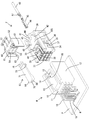
- FIG. 1 is a perspective view of the disassembled state of the female connector (connector) detached from the male connector in the first embodiment as viewed diagonally upward and forward.
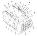
- FIG. 2 is a perspective view of a state in which the movable member and the release member are attached to the female side housing (housing) as viewed diagonally from above and behind.
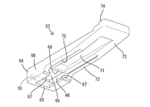
- FIG. 3 is a perspective view of the release member viewed from diagonally below and rearward.
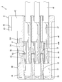
- FIG. 4 is a side sectional view showing a state in which a movable member is attached to a female side housing (housing) at a temporary locking position and a female terminal fitting (terminal fitting) is inserted into the female side housing.
- FIG. 1 is a perspective view of the disassembled state of the female connector (connector) detached from the male connector in the first embodiment as viewed diagonally upward and forward.
- FIG. 2 is a perspective view of a state in which the movable member and the release member are attached to the female side housing (housing) as
- FIG. 5 is a side sectional view showing a state in which the female terminal fitting is inserted into the female side housing and the movable member is displaced to the locked position.
- FIG. 6 is a side sectional view showing a state in which the female terminal fitting and the male terminal fitting (counterpart terminal) are not in contact with each other in the process of fitting the female connector and the male connector.
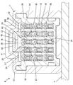
- FIG. 7 is a cross-sectional view taken along the line AA of FIG.
- FIG. 8 is a cross-sectional view taken along the line BB of FIG.
- FIG. 9 shows a state in which the movable member is displaced to the release position during the mating process of the female connector and the male connector, and the elastic contact piece of the female terminal fitting is elastically deformed in the direction away from the male terminal fitting.
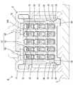
- FIG. 10 is a cross-sectional view taken along the line CC of FIG.
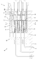
- FIG. 11 is a side sectional view showing a locked state in which the female connector and the male connector are fitted, the lock function unit is locked to the male housing (the mating housing), and both connectors are restricted from being detached.
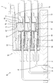
- FIG. 12 is a side sectional view showing an unlocked state in which the unlocking member is operated to dissociate the lock function portion from the male housing.
- the connectors of this disclosure are (1) A housing fitted to the mating housing and A lock function unit provided on the housing and locking the housing and the mating housing in a fitted state by locking the mating housing. It is a separate part from the housing, and includes a release member that can be attached to and detached from the housing. The release member can be displaced so as to dissociate the lock function portion from the mating housing in a state of being attached to the housing.
- the lock function portion when the mated housing and the mating housing are separated from each other, the lock function portion is displaced so as to be dissociated from the mating housing by operating the release member attached to the housing. .. Since it is possible to select the attachment / detachment of the release member to / from the housing according to the detachment frequency, only one type of housing is required. According to the present disclosure, the cost of the mold can be reduced as compared with the case of manufacturing two types of housings.
- the release member has a mounting portion to be attached to the housing and an arm portion that extends cantilevered from the mounting portion and comes into contact with the lock function portion, and the extending end portion of the arm portion.
- the lock function unit is an operation unit for displacement. According to this configuration, the lock function unit can be dissociated from the mating housing by the action of the lever by applying a small operating force to the operation unit.
- the lock function portion is formed on a movable member that is separate from the housing, and the movable member projects the lock function portion from the outer surface of the housing and locks the lock function portion to the mating housing. It is preferable that the lock position can be displaced between the lock position and the release position where the lock function portion is retracted to the inner side of the housing from the lock position and the lock function portion is dissociated from the mating housing. According to this configuration, the shape of the housing can be simplified and, by extension, the mold cost of the housing can be reduced as compared with the case where the lock function portion is integrally formed with the housing.
- the release member is attached so as to face the outer surface of the housing so as to cover a part of the lock function portion. According to this configuration, if the release member is pushed so as to approach the outer surface of the housing, the movable member can be displaced toward the release position side and the lock function portion can be dissociated from the mating housing.
- the lock function portion has a shape elongated in the width direction intersecting the fitting direction of the housing with respect to the mating housing, and the release member is a central portion of the lock function portion in the width direction. It is preferable that it covers only the shape. According to this configuration, the size of the release member in the width direction can be reduced. Further, during the unlocking operation, the unlocking member comes into contact with the central portion in the width direction of the locking function portion, so that the movable member can be displaced to the unlocking position side without tilting.
- the movable member is formed with a retaining portion for retaining the terminal fitting inserted into the housing when the movable member is in the locked position.
- the movable member has a function of locking the housing and the mating housing in a fitted state and a function of a retainer for holding out the terminal fitting. Therefore, the number of parts can be reduced as compared with the case where the retainer is provided separately from the movable member.
- the movable member can be displaced to a temporary locking position that allows insertion of the terminal fitting into the housing, and the release member has the movable member when the movable member is in the temporary locking position. It is preferable that an interference portion for restricting the attachment of the release member to the housing is formed by interfering with the housing. According to this configuration, it is possible to detect whether the movable member is in the temporary locking position or the locking position based on whether or not the releasing member can be attached to the housing.
- a terminal fitting is inserted into the housing, and the terminal fitting has an elastic contact piece that elastically contacts the mating terminal attached to the mating housing, and the movable member is elastic. It has a pressing portion that faces the contact piece, and when the movable member is in the release position, the elastic contact piece is elastically deformed so as to move away from the mating terminal by being pressed by the pressing portion. When the movable member is in the locked position, it is preferable that the elastic contact piece is released from the pressing of the pressing portion.
- the movable member when connecting the terminal fitting and the mating terminal, the movable member is displaced to the release position, and the elastic contact piece is elastically displaced in the direction away from the mating bracket.
- the fitting resistance caused by the sliding resistance between the mating terminal and the elastic contact piece can be avoided or reduced.
- the elastic contact piece released from the pressing of the pressing portion elastically contacts the mating terminal. Therefore, even if the number of poles of the terminal fitting is large, the mating terminal and the terminal fitting can be connected with a small operating force without using the boosting mechanism by the lever.
- the movable member is formed with an elastic flexure portion that elastically deforms when the movable member is displaced to the release position, and the movable member is moved from the release position by the elastic restoring force of the elastic flexure portion. It is preferable to apply an urging force in the direction of displacement to the lock position. According to this configuration, since the movable member is held in the locked position by the elastic restoring force of the elastic flexing portion, the locked state by the movable member can be maintained without using another member.
- Example 1 Example 1 that embodies the present disclosure will be described with reference to FIGS. 1 to 12. It should be noted that the present invention is not limited to these examples, and is indicated by the scope of claims, and is intended to include all modifications within the meaning and scope equivalent to the scope of claims.
- the front-back direction is defined as the front on the left side in FIGS. 4 to 6, 9, 11, and 12.
- the directions appearing in FIGS. 1 to 12 are defined as upward and downward as they are.
- the directions appearing in FIGS. 7, 8 and 10 are defined as left and right as they are.
- the female connector F of this embodiment is fitted to the male connector M.
- the male connector M has a male housing 10 mounted on the surface (upper surface) of the circuit board P, and a plurality of male terminal fittings 18 attached to the male housing 10. It is called a board connector.
- the female housing 30 has a wall-shaped terminal holding portion 11 that penetrates the male terminal fitting 18, and a square tubular hood portion 12 that protrudes from the outer peripheral edge of the terminal holding portion 11 toward the female connector F side. ..
- the upper wall portion 13 of the hood portion 12 is formed with a relief recess 14 in which the inner surface (lower surface) of the upper wall portion 13 is recessed.
- the relief recess 14 is arranged in the central portion in the left-right direction, and extends in the front-rear direction from the tip end (open end) of the hood portion 12 to the back end.
- An operation hole 15 in the form of penetrating the upper wall portion 13 is formed in a region of the upper wall portion 13 in which the relief recess 14 is formed.
- the operation hole 15 is arranged at a position slightly behind the tip of the hood portion 12.
- a pair of left and right locking portions 16 are formed on the upper wall portion 13 of the hood portion 12.
- the pair of locking locking portions 16 are arranged at portions of the upper wall portion 13 adjacent to the left and right sides of the relief recess 14 in a positional relationship spaced apart in the left-right direction.
- the locking locking portion 16 is arranged at the opening edge portion (tip portion) of the hood portion 12 in the front-rear direction, and has a locking surface 17 facing the inner side of the hood portion 12.
- the locking locking portion 16 is arranged so as to be adjacent to the front of the operation hole 15 (the opening end side of the hood portion 12).
- the pair of locking locking portions 16 are arranged at positions lower than the lower surface of the relief recess 14.
- the male terminal fitting 18 is an elongated metal rod bent into an L shape.
- the board connection portion 19 of the male terminal fitting 18 is exposed to the outside of the terminal holding portion 11 and is connected to the circuit board P in a state of being inserted into the through hole H.
- the tab 20 of the male terminal fitting 18 projects from the terminal holding portion 11 into the hood portion 12 and is connected to the female terminal fitting 45 described later.
- the female side connector F includes a female side housing 30 made of synthetic resin, a plurality of female terminal fittings 45, a movable member 52 made of synthetic resin, and a release member 63.
- the female housing 30 has a block shape as a whole. When both connectors F and M are fitted, the female housing 30 is housed in the hood portion 12.
- a plurality of terminal accommodating chambers 31 are formed in the female housing 30 so as to penetrate the female housing 30 in the front-rear direction.
- the plurality of terminal accommodating chambers 31 are arranged so as to be aligned in the vertical direction and the horizontal direction.
- An elastically deformable lance 32 is formed at the front end of the terminal accommodating chamber 31.
- the female side housing 30 has a storage space 33. As shown in FIG. 1, the accommodation space 33 opens to the outer surface 30S (upper surface) of the female housing 30 and both the left and right side surfaces, and communicates with all the terminal accommodation chambers 31.
- the accommodation space 33 is arranged at the center of the female housing 30 (position behind the lance 32) in the front-rear direction (direction orthogonal to the insertion / removal direction of the female terminal fitting 45 with respect to the female housing 30).
- a pair of left and right temporary locking portions 34 and a pair of left and right main locking portions 35 are formed on the left and right outer surfaces of the female housing 30.
- the temporary locking portion 34 and the main locking portion 35 are arranged in front of the accommodation space 33.
- the main locking portion 35 is arranged below the temporary locking portion 34.
- the temporary locking portion 34 exerts a function of holding the movable member 52 at the temporary locking position.
- the locking portion 35 exerts a function of holding the movable member 52 at the locked position.
- a pair of left and right expansion portions 36 are formed on both the left and right outer surfaces of the female side housing 30.
- the expanding portion 36 is arranged at a position below the main locking portion 35.
- the expansion portion 36 has a shape elongated in the front-rear direction over the front end side region of the accommodation space 33 and the region in front of the accommodation space 33.
- the front end side portion of the expansion portion 36 is arranged in the same region as the temporary locking portion 34 and the main locking portion 35 in the front-rear direction.
- the side surface of the expansion portion 36 is an expansion surface 37 that is oblique to the vertical direction when the female side housing 30 is viewed from the front.
- the expanding surface 37 is inclined downward so as to move away from the outer surface of the female housing 30.
- a pedestal portion 38 for attaching the movable member 52 is integrally formed on the outer surface 30S of the female side housing 30.
- the pedestal portion 38 is arranged at the front end portion of the female side housing 30 in the front-rear direction, and is arranged at the central portion of the female side housing 30 in the left-right direction (width direction).
- a pair of left and right guide portions 39 extending in the front-rear direction and projecting in a rib shape are formed on the left and right side edges of the pedestal portion 38.
- a retaining protrusion 40 is formed on the upper surface of the pedestal portion 38.
- a protective portion 41 is formed on the outer surface 30S of the female side housing 30.
- the protective portion 41 is arranged at the rear end portion of the female side housing 30, and has a pair of symmetrical protective wall portions 42 and a connecting portion 43.
- the protective wall portion 42 rises upward from the outer surface 30S of the female side housing 30.
- the connecting portion 43 is elongated in the left-right direction, and connects the front ends of the upper end edges of both the left and right protective wall portions 42.
- a notch 44 is formed in a region of the upper surface of the protective portion 41 behind the connecting portion 43. The notch 44 is sandwiched between the left and right protective wall portions 42 and is opened to the rear of the protective portion 41.
- the female terminal fitting 45 is formed by bending a metal plate material or the like to form an elongated shape in the front-rear direction as a whole. As shown in FIGS. 1 and 4, a square cylinder portion 46 is formed at the front end portion of the female terminal fitting 45. A crimping portion 47 is formed at the rear end portion of the female terminal fitting 45, and the crimping portion 47 is crimped to the front end portion of the electric wire 48.
- the female terminal fitting 45 is inserted into the terminal accommodating chamber 31 from the rear of the female housing 30, and is released by the locking action of the lance 32. When the female terminal fitting 45 is inserted into the normal position of the terminal accommodating chamber 31, the rear end edge portion 46R of the square tube portion 46 is positioned so as to be adjacent to the front of the front end of the accommodating space 33.
- the female terminal fitting 45 has an elastic contact piece 49 that elastically contacts the tab 20 of the male terminal fitting 18.
- the elastic contact piece 49 is folded back from the front end of the lower plate portion constituting the square tube portion 46 and extends in a cantilever shape.
- a contact portion 50 that makes point contact or line contact with the tab 20 is formed at a position slightly rearward of the front end of the elastic contact piece 49.
- the rear end portion (extending end portion) of the elastic contact piece 49 functions as a pressure receiving portion 51.
- Most of the elastic contact piece 49 except the pressure receiving portion 51 and including the contact portion 50 is housed in the square tube portion 46.
- the pressure receiving portion 51 projects rearward from the rear end of the square tube portion 46.
- the movable member 52 is an independent synthetic resin part separate from the female side housing 30. As shown in FIG. 1, the movable member 52 is a symmetrical single component having a main body portion 53 having a square front view shape when viewed from the front, a lock function portion 57, and a pair of elastic bending portions 61. is there.
- the main body 53 has a plurality of through holes 54 aligned in the vertical direction and the horizontal direction. In front view, the plurality of through holes 54 are aligned in the vertical direction and the horizontal direction.
- the alignment form of the through holes 54 is the same as the alignment form of the plurality of terminal accommodating chambers 31. As shown in FIG.
- each through hole 54 in the front surface of the main body portion 53 functions as a retaining portion 55.
- the front end portion on the upper surface of each through hole 54 functions as a pressing portion 56 facing downward.
- the pressing portion 56 and the retaining portion 55 are connected at a right angle.
- the lock function portion 57 protrudes upward from the upper wall portion 13 of the main body portion 53 and extends in the left-right direction.
- the central portion of the lock function portion 57 in the left-right direction functions as a receiving portion 58.
- the left and right ends of the lock function portion 57 function as lock portions 59.
- the pair of lock portions 59 are arranged so as to sandwich the receiving portion 58 from both the left and right sides.
- the receiving portion 58 and the pair of locking portions 59 are continuously connected.
- An induction surface 60 is formed on the upper surface of the lock function portion 57 so as to be lowered toward the front.
- the pair of elastic flexing portions 61 have a cantilevered shape extending forward from the front end edges of the left and right side wall portions of the main body portion 53.
- the pair of elastic flexing portions 61 have a rectangular plate shape and can be elastically deformed so as to expand each other.
- the lower end edge of the elastic flexure portion 61 has a locking edge portion protruding from the inner surface of the elastic flexure portion 61 (the surface facing the elastic flexure portion 61 on the other side). 62 is formed.
- the movable member 52 accommodates the main body 53 in the accommodation space 33 from above the female housing 30, and the female housing in a state where the pair of elastic flexing portions 61 are overlapped on the left and right outer surfaces of the female housing 30. It is attached to 30.
- the movable member 52 is a component having multiple functions, and when attached to the female side housing 30, it exhibits a retainer function, a fitting force reducing function, and a locking function.
- the retainer function detects the inserted state of the female terminal fitting 45 in the female housing 30 (terminal accommodating chamber 31) and retains the female terminal fitting 45 inserted in the female housing 30 (terminal accommodating chamber 31). Is.
- the fitting force reducing function is a function of reducing the fitting resistance caused by friction between the female terminal fitting 45 and the male terminal fitting 18 in the fitting process of both connectors F and M.
- the lock function is a function of locking both normally fitted connectors F and M (both housings 10 and 30) in a detachment restricted state.
- the movable member 52 attached to the female housing 30 has a temporary locking position (see FIG. 4), a locking position (see FIGS. 2, 5, 6, 8 and 11), and an unlocking position (see FIGS. 9, 10, 11). It is designed to be held in three positions (see 12).
- the temporary locking position is set to the highest position among the three positions.
- the movable member 52 is held at the temporary locking position by vertically sandwiching the locking edge portion 62 between the temporary locking portion 34 and the main locking portion 35.
- the movable member 52 held in the temporarily locked position is in a ready state in which the inserted state of the female terminal fitting 45 can be detected.
- the lock position is set lower than the temporary lock position and higher than the release position.
- the movable member 52 is held at the locked position by vertically sandwiching the locking edge portion 62 between the main locking portion 35 and the expanding surface 37.
- the movable member 52 held at the locked position can exhibit a function of retaining the female terminal fitting 45 and a function of locking both connectors F and M in the fitted state.
- the release position is set to the lowest position among the three positions.
- the movable member 52 at the release position loses the function of locking both connectors F and M in the fitted state, and exhibits the function of reducing the fitting resistance. Further, when the movable member 52 is in the release position, as shown in FIG. 10, the lower end portions of the pair of elastic flexing portions 61 are deformed by the expanding portion 36 so as to be curved outward in the left-right direction (width direction). Therefore, the elastic restoring force is stored in the elastic bending portion 61.
- the release member 63 is a component made of synthetic resin that is independent of the female side housing 30 and the movable member 52.
- the release member 63 is a component for performing an operation of releasing the locked state of both connectors F and M (both housings 10 and 30) locked in the fitted state by the movable member 52.
- the release member 63 is a plate-shaped component elongated in the front-rear direction as a whole.
- the release member 63 has a mounting portion 64, an arm portion 71, and an operating portion 74, and has a symmetrical shape.
- the mounting portion 64 is formed at the front end portion of the release member 63.
- the mounting portion 64 includes an upper plate portion 65 whose plate thickness direction is directed in the vertical direction, left and right side plate portions 66, a pair of left and right sliding contact portions 67, a hooking portion 68, and a front stop portion 69.
- the left and right side plate portions 66 extend downward from the left and right side edge portions of the upper plate portion 65.
- the pair of left and right sliding contact portions 67 project inward (center side in the left-right direction) from the lower end edges of the left and right side plate portions 66 in a rib shape.
- the hook portion 68 has a form protruding downward from the rear end edge of the upper plate portion 65.
- the front stop portion 69 is connected to the front end edge of the upper plate portion 65 and the front end edges of the left and right side edges.
- the front stop portion 69 is opened with a die-cutting hole 70 formed when the hook portion 68 is molded.
- the arm portion 71 is aligned with the rear end edge of the upper plate portion 65 and extends rearward from the upper plate portion 65 in a cantilever shape.
- a pair of left and right contact portions 72 are formed on the lower surface of the arm portion 71.
- the contact portion 72 protrudes downward from the left and right side edges of the arm portion 71 and extends in the front-rear direction.
- the forming region of the contact portion 72 in the front-rear direction is a range extending from the rear end of the side plate portion 66 of the mounting portion 64 to the central portion in the front-rear direction of the arm portion 71.
- An interference portion 73 is formed on the lower surface of the arm portion 71.
- the interference portion 73 is formed from the central portion in the front-rear direction of the arm portion 71 to the rear end of the arm portion 71.
- the front end side region of the interference portion 73 is arranged on the left and right side edges of the arm portion 71, and is connected to the rear end of the contact portion 72.
- the rear end portion of the interference portion 73 extends over the entire width of the arm portion 71.
- the lower surface of the interference portion 73 is inclined so as to be lowered toward the front.
- the operation portion 74 is formed at the rear end portion of the arm portion 71.
- the operation unit 74 has a shape protruding stepwise from the upper surface of the arm unit 71.
- the stepped protrusion makes it difficult for the finger on the operation unit 74 to come off rearward.
- the operation unit 74 can apply a downward pressing force from above the release member 63.
- the release member 63 is removable from the female housing 30, but the necessity of attachment / detachment can be arbitrarily selected according to the frequency with which both connectors F and M are detached. That is, when the lock by the movable member 52 is frequently released, the release member 63 is attached to the female side housing 30. When the lock by the movable member 52 is released infrequently, both connectors F and M are fitted without attaching the release member 63 to the female side housing 30.
- the movable member 52 is attached to the female side housing 30 and held at the temporary locking position.
- the height of the through hole 54 matches the height of the terminal accommodating chamber 31, and the retaining portion 55 retracts above the insertion path of the female terminal fitting 45 with respect to the terminal accommodating chamber 31. .. Therefore, the female terminal fitting 45 can be inserted and removed from the terminal accommodating chamber 31.
- the female terminal fitting 45 is inserted into the terminal accommodating chamber 31 while the movable member 52 is held at the temporarily locked position.
- the movable member 52 If there is a female terminal fitting 45 that has not been inserted to the normal position when all the female terminal fittings 45 have been inserted, the movable member 52 is pushed down from the temporary locking position to the locking position. At this time, the pressing portion 56 hits the upper surface of the square cylinder portion 46. Therefore, the movable member 52 cannot be pushed down to the locked position. Therefore, based on whether or not the movable member 52 in the temporarily locked position can be pushed into the locked position, the female terminal fitting 45 is in the inserted state (that is, all the female terminal fittings 45 are normally inserted or semi-inserted). (Whether the female terminal fitting 45 is present) can be detected.
- the release member 63 is attached to the female side housing 30.
- the mounting portion 64 is brought closer to the pedestal portion 38 from the front of the female side housing 30 while covering the pedestal portion 38 with the arm portion 71 from above.
- the hook portion 68 is brought into sliding contact with the upper surface of the pedestal portion 38, and the side plate portion 66 and the sliding contact portion 67 are brought into sliding contact with the side surface and the lower surface of the guide portion 39.
- the release member 63 is attached in a state where the relative displacement in the vertical direction and the horizontal direction is restricted with respect to the pedestal portion 38 and is held in a constant posture.
- the hooking portion 68 gets over the retaining protrusion 40 and comes into contact with the retaining protrusion 40 from the rear, and the front stop portion 69 is a pedestal. It contacts the portion 38 from the front. By this contact action, the release member 63 is held in a state where the movement in the front-rear direction is restricted with respect to the pedestal portion 38 (female side housing 30).
- the lower surface of the contact portion 72 faces the receiving portion 58 of the lock function portion 57 in a positional relationship close to each other from above.
- the pair of left and right lock portions 59 are exposed upward on both the left and right sides of the release member 63.
- the operating portion 74 is housed in the protective portion 41, is sandwiched between the left and right protective wall portions 42, and is located below the connecting portion 43.
- the cutout portion 44 is formed on the upper surface portion of the protective portion 41, it is possible to accommodate a finger between the left and right protective wall portions 42 and push the operation portion 74 from above with the finger. is there.
- the release member 63 when the release member 63 is to be attached to the pedestal portion 38 while the movable member 52 is in the temporarily locked position, the hook portion 68 comes into contact with the upper surface of the pedestal portion 38 and becomes the side plate portion 66. Immediately after the sliding contact portion 67 comes into contact with the side surface and the lower surface of the guide portion 39 and the release member 63 is held in a constant mounting posture, the lower surface of the interference portion 73 of the release member 63 is subjected to the receiving portion 58 (lock function portion 57). ) Interferes. If the release member 63 is assembled in this state, the sliding friction between the inclined lower surface of the interference portion 73 and the receiving portion 58 increases, so that the resistance to the assembly increases. Therefore, it becomes difficult to proceed with the attachment of the release member 63.
- the hook portion 68 abuts on the retaining protrusion 40, so that the assembly resistance increases at once. Therefore, even if the assembly is forcibly proceeded, it becomes difficult to attach the release member 63 before the normal assembly state is reached. Therefore, there is no possibility that the release member 63 will be attached to the female side housing 30 while the movable member 52 is in the temporarily locked position. Further, it is possible to detect whether or not the movable member 52 has moved to the lock position based on whether or not the release member 63 can be attached.
- the movable member 52 at the temporarily locked position can be pushed down to the locked position by the inclined lower surface of the interference portion 73. .. In this case, a considerably large force is required, but as soon as the assembly of the release member 63 is completed, the movable member 52 is held in the locked position.
- the fitting resistance between both connectors F and M is reduced.
- the release member 63 is housed in the relief recess 14, so that the release member 63 is not deformed or displaced by contact with the hood portion 12.
- the locking edge portion 62 of the elastic flexure portion 61 is elastically deformed so as to expand by sliding contact with the expansion portion 36. Be done.
- the elastic restoring force is stored in the elastic flexing portion 61, so that the movable member 52 tends to move to the lock position side.
- the movable member 52 is given a returning force to the lock position side by the elastic restoring force of the elastic contact piece 49.
- the lock portion 59 (lock function portion 57) passes through the lock locking portion 16, so that the movable member 52 elastically returns from the release position to the lock position. To do.
- the lock function portion 57 is displaced so as to protrude from the outer surface 30S of the female side housing 30, and the left and right lock portions 59 are displaced from the locking surface 17 of the left and right lock locking portions 16. Lock to.
- both connectors F and M are locked in a state in which disconnection is restricted.
- the pressing portion 56 dissociates from the pressure receiving portion 51, so that the elastic contact piece 49 elastically returns in the direction approaching the tab 20, and the tab 20 and the elastic contact piece 49 are located. It is connected by the contact pressure of the period.
- the release member 63 does not move from the start of fitting of both connectors F and M to the completion of fitting.
- the operation portion 74 of the release member 63 When disengaging both connectors F and M in the fitted state, the operation portion 74 of the release member 63 is pushed and operated to displace the arm portion 71 so as to approach the outer surface 30S of the female side housing 30. At this time, the release member 63 is elastically deformed. By pushing the operation unit 74, the contact portion 72 of the release member 63 presses the receiving portion 58, so that the movable member 52 at the lock position is pushed down to the release position. When the movable member 52 moves to the release position, the lock function portion 57 is housed in the female side housing 30 (inside the accommodation space 33), and the lock portion 59 is dissociated from the lock locking portion 16 (locking surface 17). As a result, the locked state by the lock portion 59 is released, so that the connectors F and M (both housings 10 and 30) may be separated while maintaining the unlocked state.
- both connectors F and M both housings 10 and 30
- both connectors F and M are detached while maintaining the state in which the movable member 52 is pushed to the release position with a jig, a tool, or a finger.
- the detachment of both connectors F and M is completed by removing the jig, the tool or the finger from the movable member 52.
- the female side connector F of the first embodiment includes a female side housing 30 fitted to the male side housing 10, a lock function portion 57 provided in the female side housing 30, and a release member 63.
- the lock function portion 57 locks the female side housing 30 and the male side housing 10 in a fitted state by locking the male side housing 10.
- the release member 63 is a separate part from the female housing 30, and is removable from the female housing 30. The release member 63 can be displaced so as to dissociate the lock function portion 57 from the male housing 10 when the release member 63 is attached to the female housing 30.
- the lock function portion 57 is dissected from the male housing 10 by operating the release member 63 attached to the female housing 30. Displace. Since it is possible to select the attachment / detachment of the release member 63 to / from the female side housing 30 according to the detachment frequency, only one type of female side housing 30 is required. Therefore, according to the female side connector F of this embodiment, the cost of the mold can be reduced as compared with the case of manufacturing the two types of female side housings 30.
- the release member 63 has a mounting portion 64 that is attached to the female housing 30, and an arm portion 71 that extends cantilevered from the mounting portion 64 and abuts on the lock function portion 57.
- the extending end portion of the arm portion 71 is an operating portion 74 for displacing the lock function portion 57 in the unlocking direction.
- the operation unit 74 When the operation unit 74 is operated, the arm unit 71 is displaced so as to tilt its posture with the mounting unit 64 as a fulcrum, and pushes and moves the lock function unit 57.
- the portion of the arm portion 71 that comes into contact with the lock function portion 57 is closer to the mounting portion 64 than the operating portion 74. Therefore, by simply applying a small operating force to the operating unit 74, the lock function unit 57 can be moved and dissociated from the male housing 10 by the action of the lever.
- the lock function portion 57 is formed on a movable member 52 that is separate from the female side housing 30.
- the movable member 52 can be displaced between the lock position and the release position retracted to the inner side (inside the accommodation space 33) of the female housing 30 from the lock position.
- the lock function portion 57 protrudes from the outer surface 30S of the female housing 30 and is locked to the male housing 10.
- the lock function portion 57 dissociates from the male housing 10.
- the lock function portion 57 is formed on a movable member 52 that is separate from the female side housing 30, the shape of the female side housing 30 is as compared with the case where the lock function portion 57 is integrally formed with the female side housing 30. Can be simplified. Thereby, the mold cost of the female side housing 30 can be reduced.
- the release member 63 is attached so as to face the outer surface 30S of the female side housing 30 in a form of covering a part of the lock function portion 57 (only the receiving portion 58 in the center in the left-right direction). Therefore, if the release member 63 is pushed so as to approach the outer surface 30S of the female side housing 30, the movable member 52 can be displaced toward the release position side and the lock function portion 57 can be dissociated from the male side housing 10.
- the lock function portion 57 has a shape elongated in the width direction (left-right direction) intersecting the fitting direction of the female side housing 30 with respect to the male side housing 10, and the release member 63 is the center of the lock function portion 57 in the width direction. It is a form that covers only the portion (receiving portion 58). According to this configuration, the size of the release member 63 in the width direction can be reduced. Further, during the unlocking operation, the unlocking member 63 comes into contact with the central portion in the width direction of the locking function portion 57, so that the movable member 52 can be displaced to the unlocking position side without tilting.
- the movable member 52 is formed with a retaining portion 55.
- the retaining portion 55 retains the female terminal fitting 45 inserted into the female housing 30. That is, the movable member 52 has not only the function of locking the female side housing 30 and the male side housing 10 in the fitted state, but also the function of a retainer for retaining the female terminal fitting 45. Therefore, the female side connector F of the present embodiment can reduce the number of parts as compared with the case where the retainer is provided separately from the movable member 52.
- the movable member 52 can be displaced to a temporary locking position that allows the female terminal fitting 45 to be inserted into the female housing 30.
- the release member 63 is formed with an interference portion 73 that regulates the attachment of the release member 63 to the female housing 30 by interfering with the movable member 52 when the movable member 52 is in the temporarily locked position. According to this configuration, it is possible to detect whether the movable member 52 is in the temporary locking position or the locking position based on whether or not the releasing member 63 can be attached to the female side housing 30. ..
- the female terminal fitting 45 is inserted into the female housing 30.
- the female terminal fitting 45 has an elastic contact piece 49 that elastically contacts the male terminal fitting 18 attached to the male housing 10.
- the movable member 52 has a pressing portion 56 facing the elastic contact piece 49. When the movable member 52 is in the release position, the elastic contact piece 49 is elastically displaced in the direction away from the tab 20 of the male terminal fitting 18 by being pressed by the pressing portion 56. When the movable member 52 is in the locked position, the elastic contact piece 49 is released from the pressing of the pressing portion 56.
- the movable member 52 when connecting the female terminal fitting 45 and the male terminal fitting 18, the movable member 52 is displaced to the release position, and the elastic contact piece 49 is elastically displaced in the direction away from the male terminal fitting 18. Keep it. Thereby, the fitting resistance caused by the sliding resistance between the male terminal fitting 18 and the elastic contact piece 49 can be avoided or reduced.
- the elastic contact piece 49 released from the pressing of the pressing portion 56 elastically contacts the male terminal fitting 18. To do. Therefore, even if the number of poles of the female terminal fitting 45 is large, the male terminal fitting 18 and the female terminal fitting 45 can be connected with a small operating force without using the boosting mechanism by the lever.
- the movable member 52 is formed with an elastic flexible portion 61 that elastically deforms when the movable member 52 is displaced to the release position.
- the movable member 52 is given an urging force in the direction of displacement from the release position to the lock position by the elastic restoring force of the elastic flexure portion 61. According to this configuration, since the movable member 52 is held in the locked position by the elastic restoring force of the elastic flexing portion 61, the locked state by the movable member 52 can be maintained without using another member.
- the present invention is not limited to the examples described in the above description and drawings, but is shown by the scope of claims.
- the present invention includes meaning equivalent to the scope of claims and all modifications within the scope of claims, and is intended to include embodiments such as:
- the lock by the lock function portion is released by bringing the release member close to the outer surface of the housing, but the displacement direction of the release member at the time of unlocking is parallel to the outer surface of the housing. It may be in any direction.
- the unlocking member is pushed during the unlocking operation, but the unlocking member may be pulled to unlock the lock.
- the release member covers only the central portion in the width direction of the lock function portion, but the release member may cover both ends in the width direction of the lock function portion. In this case, the central portion of the lock function portion in the width direction is locked to the mating housing.
- the release member is cantilevered backward, but the release member may be cantilevered forward or sideways.
- the release member is attached to the housing in a cantilevered manner, but the release member may be attached to the housing in a cantilever shape.
- the mounting portion of the release member is fixed to the housing, and the release member is elastically deformed to dissociate the lock function portion from the mating housing.
- the release member has a shaft with respect to the housing.
- the movable member when the movable member is in the temporary locking position, the interference portion of the release member interferes with the movable member, but the release member may have no interference portion. In this case, the release member can be attached to the housing even when the movable member is in the temporarily locked position.
- the movable member also has a function as a retainer for holding out the terminal fitting, but the movable member may not have a function as a retainer.
- the lock function portion is formed on a movable member separate from the housing, but the lock function portion may be integrally formed on the housing.
- the lock function portion is displaced from the outer surface of the housing in the direction of protrusion to lock the mating housing, but the lock function portion is displaced along the outer surface of the housing. As a result, it may be locked to the housing on the other side.
- the movable member has a function of avoiding or reducing the fitting resistance caused by the sliding resistance between the terminal fitting and the mating terminal, but the movable member avoids the fitting resistance. Alternatively, it may not have a function of reducing.
- Female terminal metal fittings (terminal metal fittings) 46 Square tube 46R ... Rear edge edge 47 of the square tube 47 ... Crimping part 48 ... Electric wire 49 ... Elastic contact piece 50 ... Contact 51 ... Pressure receiving part 52 ... Movable member 53 ... Main body 54 ... Through hole 55 ... Extraction Stopping part 56 ... Pressing part 57 ... Locking function part 58 ... Receiving part 59 ... Locking part 60 ... Guide surface 61 ... Elastic bending part 62 ... Locking edge part 63 ... Release member 64 ... Mounting part 65 ... Top plate part 66 ... Side plate Part 67 ... Sliding contact part 68 ... Hooking part 69 ... Front stop part 70 ... Die-cutting hole 71 ... Arm part 72 ... Pad part 73 ... Interference part 74 ... Operation part F ... Female side connector (connector) H ... Through hole M ... Male side connector P ... Circuit board
Landscapes
- Details Of Connecting Devices For Male And Female Coupling (AREA)
- Connector Housings Or Holding Contact Members (AREA)
Abstract
La présente invention réduit le coût. Un connecteur latéral femelle (F) comporte : un boîtier latéral femelle (30) adapté à un logement latéral mâle (10) ; une partie à fonction de verrouillage (57) qui est disposée sur le boîtier latéral femelle (30) et qui verrouille, de manière ajustée, le boîtier latéral femelle (30) et le boîtier côté mâle (10) par verrouillage du boîtier côté mâle (10) ; et un élément de libération (63) qui est un composant séparé du boîtier côté femelle (30) et qui peut être fixé au boîtier côté femelle et détaché de celui-ci (30), l'élément de libération (63) pouvant amener la partie de fonction de verrouillage (57) à être déplacée de façon à être libérée et séparée du boîtier latéral mâle (10) dans un état dans lequel l'élément de libération est fixé au boîtier latéral femelle (30).
Priority Applications (2)
| Application Number | Priority Date | Filing Date | Title |
|---|---|---|---|
| US17/629,558 US11848519B2 (en) | 2019-08-07 | 2020-07-17 | Connector |
| CN202080054116.7A CN114175416B (zh) | 2019-08-07 | 2020-07-17 | 连接器 |
Applications Claiming Priority (2)
| Application Number | Priority Date | Filing Date | Title |
|---|---|---|---|
| JP2019-145079 | 2019-08-07 | ||
| JP2019145079A JP7251398B2 (ja) | 2019-08-07 | 2019-08-07 | コネクタ |
Publications (1)
| Publication Number | Publication Date |
|---|---|
| WO2021024756A1 true WO2021024756A1 (fr) | 2021-02-11 |
Family
ID=74503528
Family Applications (1)
| Application Number | Title | Priority Date | Filing Date |
|---|---|---|---|
| PCT/JP2020/027815 WO2021024756A1 (fr) | 2019-08-07 | 2020-07-17 | Connecteur |
Country Status (4)
| Country | Link |
|---|---|
| US (1) | US11848519B2 (fr) |
| JP (1) | JP7251398B2 (fr) |
| CN (1) | CN114175416B (fr) |
| WO (1) | WO2021024756A1 (fr) |
Families Citing this family (2)
| Publication number | Priority date | Publication date | Assignee | Title |
|---|---|---|---|---|
| CA3150339A1 (fr) | 2019-09-12 | 2021-03-18 | Brian W. Donovan | Systemes et methodes de modulation de tissu |
| JP7240616B2 (ja) * | 2020-09-24 | 2023-03-16 | 住友電装株式会社 | コネクタ |
Citations (3)
| Publication number | Priority date | Publication date | Assignee | Title |
|---|---|---|---|---|
| JP2001217041A (ja) * | 1999-11-26 | 2001-08-10 | Sumitomo Wiring Syst Ltd | コネクタ |
| JP2006216434A (ja) * | 2005-02-04 | 2006-08-17 | Yazaki Corp | ロックコネクタ |
| JP2013214437A (ja) * | 2012-04-03 | 2013-10-17 | Auto Network Gijutsu Kenkyusho:Kk | コネクタ及び電気接続装置 |
Family Cites Families (22)
| Publication number | Priority date | Publication date | Assignee | Title |
|---|---|---|---|---|
| FR2730587B3 (fr) * | 1995-02-09 | 1997-04-30 | Amp France | Connecteur electrique a mecanismes de verrouillage secondaire et d'accouplement |
| JP4500245B2 (ja) * | 2005-10-27 | 2010-07-14 | 矢崎総業株式会社 | コネクタ |
| JP2008270127A (ja) * | 2007-04-25 | 2008-11-06 | Sumitomo Wiring Syst Ltd | コネクタ |
| JP4986970B2 (ja) * | 2008-10-20 | 2012-07-25 | 矢崎総業株式会社 | コネクタ |
| US8882528B2 (en) * | 2010-12-15 | 2014-11-11 | Sumitomo Wiring Systems, Ltd. | Connector |
| JP5724836B2 (ja) * | 2011-11-09 | 2015-05-27 | 住友電装株式会社 | コネクタ |
| JP6249297B2 (ja) * | 2014-11-04 | 2017-12-20 | 住友電装株式会社 | コネクタ |
| JP6443098B2 (ja) * | 2015-02-06 | 2018-12-26 | 株式会社オートネットワーク技術研究所 | コネクタ |
| JP2016225027A (ja) * | 2015-05-27 | 2016-12-28 | 住友電装株式会社 | コネクタ |
| JP6191661B2 (ja) * | 2015-07-30 | 2017-09-06 | 住友電装株式会社 | コネクタ |
| EP3252880B1 (fr) * | 2016-06-02 | 2020-05-20 | Aptiv Technologies Limited | Ensemble de connecteur électrique avec dispositif de verrouillage amélioré |
| US10770808B2 (en) * | 2016-09-21 | 2020-09-08 | Pct International, Inc. | Connector with a locking mechanism |
| EP3316427B1 (fr) * | 2017-01-17 | 2023-09-13 | J.S.T. Corporation | Procédé de fonctionnement d'une série de connecteurs msl |
| US10367299B2 (en) * | 2017-03-29 | 2019-07-30 | Foxconn Interconnect Technology Limited | Plug connector assembly with an unlocking apparatus for unlocking a latch |
| JP6876497B2 (ja) * | 2017-04-14 | 2021-05-26 | タイコエレクトロニクスジャパン合同会社 | 電気コネクタ |
| JP6876498B2 (ja) * | 2017-04-14 | 2021-05-26 | タイコエレクトロニクスジャパン合同会社 | 電気コネクタ |
| JP6840634B2 (ja) * | 2017-06-26 | 2021-03-10 | 日本航空電子工業株式会社 | コネクタ |
| US10367295B2 (en) * | 2017-07-11 | 2019-07-30 | Moxa Inc. | Clamping mechanism for industrial input/output device |
| US10283904B2 (en) * | 2017-08-04 | 2019-05-07 | Yazaki Corporation | Connector |
| JP6978283B2 (ja) | 2017-11-07 | 2021-12-08 | 矢崎総業株式会社 | コネクタ |
| JP6939530B2 (ja) * | 2017-12-26 | 2021-09-22 | 住友電装株式会社 | コネクタ |
| JP7052943B2 (ja) * | 2018-02-16 | 2022-04-12 | 住友電工デバイス・イノベーション株式会社 | 光トランシーバ |
-
2019
- 2019-08-07 JP JP2019145079A patent/JP7251398B2/ja active Active
-
2020
- 2020-07-17 CN CN202080054116.7A patent/CN114175416B/zh active Active
- 2020-07-17 US US17/629,558 patent/US11848519B2/en active Active
- 2020-07-17 WO PCT/JP2020/027815 patent/WO2021024756A1/fr active Application Filing
Patent Citations (3)
| Publication number | Priority date | Publication date | Assignee | Title |
|---|---|---|---|---|
| JP2001217041A (ja) * | 1999-11-26 | 2001-08-10 | Sumitomo Wiring Syst Ltd | コネクタ |
| JP2006216434A (ja) * | 2005-02-04 | 2006-08-17 | Yazaki Corp | ロックコネクタ |
| JP2013214437A (ja) * | 2012-04-03 | 2013-10-17 | Auto Network Gijutsu Kenkyusho:Kk | コネクタ及び電気接続装置 |
Also Published As
| Publication number | Publication date |
|---|---|
| JP7251398B2 (ja) | 2023-04-04 |
| US11848519B2 (en) | 2023-12-19 |
| CN114175416A (zh) | 2022-03-11 |
| JP2021026929A (ja) | 2021-02-22 |
| US20220271473A1 (en) | 2022-08-25 |
| CN114175416B (zh) | 2024-05-10 |
Similar Documents
| Publication | Publication Date | Title |
|---|---|---|
| EP1571734B1 (fr) | Dispositif de connexion ayant un élément de détection de l'engagement appelé assurance de position de connecteurs | |
| KR101271347B1 (ko) | 커넥터, 커넥터 조립체 및 접속 방법 | |
| JP3800312B2 (ja) | コネクタ | |
| US5820399A (en) | Connector fitting construction | |
| JP3468451B2 (ja) | コネクタ嵌合構造 | |
| JP3420918B2 (ja) | 半嵌合防止コネクタ | |
| JP4174149B2 (ja) | 半嵌合防止コネクタ | |
| JPH0831517A (ja) | コネクタ嵌合検知構造 | |
| JP2004327321A (ja) | コネクタ | |
| JP2004103551A (ja) | コネクタ | |
| CA2353425C (fr) | Structure de raccordement de connecteur | |
| JP2008543026A (ja) | 端子位置保証装置を有するコネクタ組立体 | |
| WO2021024756A1 (fr) | Connecteur | |
| WO2021024750A1 (fr) | Connecteur | |
| JP3741351B2 (ja) | 半嵌合防止コネクタ | |
| JP4496475B2 (ja) | コネクタ | |
| JP7042402B2 (ja) | コネクタ | |
| JP2022034739A (ja) | コネクタおよびコネクタ組立体 | |
| JP4306573B2 (ja) | コネクタ | |
| CN113939960A (zh) | 阴连接器及连接器 | |
| JP4631730B2 (ja) | コネクタ | |
| JP3783850B2 (ja) | コネクタ | |
| WO2021182026A1 (fr) | Connecteur de bord de carte | |
| WO2023153258A1 (fr) | Connecteur | |
| JP3783852B2 (ja) | コネクタ |
Legal Events
| Date | Code | Title | Description |
|---|---|---|---|
| 121 | Ep: the epo has been informed by wipo that ep was designated in this application |
Ref document number: 20850551 Country of ref document: EP Kind code of ref document: A1 |
|
| NENP | Non-entry into the national phase |
Ref country code: DE |
|
| 122 | Ep: pct application non-entry in european phase |
Ref document number: 20850551 Country of ref document: EP Kind code of ref document: A1 |