WO2021024756A1 - コネクタ - Google Patents
コネクタ Download PDFInfo
- Publication number
- WO2021024756A1 WO2021024756A1 PCT/JP2020/027815 JP2020027815W WO2021024756A1 WO 2021024756 A1 WO2021024756 A1 WO 2021024756A1 JP 2020027815 W JP2020027815 W JP 2020027815W WO 2021024756 A1 WO2021024756 A1 WO 2021024756A1
- Authority
- WO
- WIPO (PCT)
- Prior art keywords
- housing
- movable member
- lock function
- release
- female
- Prior art date
Links
Images


Classifications
-
- H—ELECTRICITY
- H01—ELECTRIC ELEMENTS
- H01R—ELECTRICALLY-CONDUCTIVE CONNECTIONS; STRUCTURAL ASSOCIATIONS OF A PLURALITY OF MUTUALLY-INSULATED ELECTRICAL CONNECTING ELEMENTS; COUPLING DEVICES; CURRENT COLLECTORS
- H01R13/00—Details of coupling devices of the kinds covered by groups H01R12/70 or H01R24/00 - H01R33/00
- H01R13/62—Means for facilitating engagement or disengagement of coupling parts or for holding them in engagement
- H01R13/639—Additional means for holding or locking coupling parts together, after engagement, e.g. separate keylock, retainer strap
-
- H—ELECTRICITY
- H01—ELECTRIC ELEMENTS
- H01R—ELECTRICALLY-CONDUCTIVE CONNECTIONS; STRUCTURAL ASSOCIATIONS OF A PLURALITY OF MUTUALLY-INSULATED ELECTRICAL CONNECTING ELEMENTS; COUPLING DEVICES; CURRENT COLLECTORS
- H01R13/00—Details of coupling devices of the kinds covered by groups H01R12/70 or H01R24/00 - H01R33/00
- H01R13/62—Means for facilitating engagement or disengagement of coupling parts or for holding them in engagement
- H01R13/629—Additional means for facilitating engagement or disengagement of coupling parts, e.g. aligning or guiding means, levers, gas pressure electrical locking indicators, manufacturing tolerances
- H01R13/633—Additional means for facilitating engagement or disengagement of coupling parts, e.g. aligning or guiding means, levers, gas pressure electrical locking indicators, manufacturing tolerances for disengagement only
-
- H—ELECTRICITY
- H01—ELECTRIC ELEMENTS
- H01R—ELECTRICALLY-CONDUCTIVE CONNECTIONS; STRUCTURAL ASSOCIATIONS OF A PLURALITY OF MUTUALLY-INSULATED ELECTRICAL CONNECTING ELEMENTS; COUPLING DEVICES; CURRENT COLLECTORS
- H01R13/00—Details of coupling devices of the kinds covered by groups H01R12/70 or H01R24/00 - H01R33/00
- H01R13/40—Securing contact members in or to a base or case; Insulating of contact members
- H01R13/42—Securing in a demountable manner
- H01R13/436—Securing a plurality of contact members by one locking piece or operation
- H01R13/4361—Insertion of locking piece perpendicular to direction of contact insertion
- H01R13/4362—Insertion of locking piece perpendicular to direction of contact insertion comprising a temporary and a final locking position
-
- H—ELECTRICITY
- H01—ELECTRIC ELEMENTS
- H01R—ELECTRICALLY-CONDUCTIVE CONNECTIONS; STRUCTURAL ASSOCIATIONS OF A PLURALITY OF MUTUALLY-INSULATED ELECTRICAL CONNECTING ELEMENTS; COUPLING DEVICES; CURRENT COLLECTORS
- H01R13/00—Details of coupling devices of the kinds covered by groups H01R12/70 or H01R24/00 - H01R33/00
- H01R13/40—Securing contact members in or to a base or case; Insulating of contact members
- H01R13/42—Securing in a demountable manner
- H01R13/426—Securing by a separate resilient retaining piece supported by base or case, e.g. collar or metal contact-retention clip
-
- H—ELECTRICITY
- H01—ELECTRIC ELEMENTS
- H01R—ELECTRICALLY-CONDUCTIVE CONNECTIONS; STRUCTURAL ASSOCIATIONS OF A PLURALITY OF MUTUALLY-INSULATED ELECTRICAL CONNECTING ELEMENTS; COUPLING DEVICES; CURRENT COLLECTORS
- H01R13/00—Details of coupling devices of the kinds covered by groups H01R12/70 or H01R24/00 - H01R33/00
- H01R13/46—Bases; Cases
-
- H—ELECTRICITY
- H01—ELECTRIC ELEMENTS
- H01R—ELECTRICALLY-CONDUCTIVE CONNECTIONS; STRUCTURAL ASSOCIATIONS OF A PLURALITY OF MUTUALLY-INSULATED ELECTRICAL CONNECTING ELEMENTS; COUPLING DEVICES; CURRENT COLLECTORS
- H01R13/00—Details of coupling devices of the kinds covered by groups H01R12/70 or H01R24/00 - H01R33/00
- H01R13/62—Means for facilitating engagement or disengagement of coupling parts or for holding them in engagement
- H01R13/627—Snap or like fastening
- H01R13/6271—Latching means integral with the housing
- H01R13/6272—Latching means integral with the housing comprising a single latching arm
-
- H—ELECTRICITY
- H01—ELECTRIC ELEMENTS
- H01R—ELECTRICALLY-CONDUCTIVE CONNECTIONS; STRUCTURAL ASSOCIATIONS OF A PLURALITY OF MUTUALLY-INSULATED ELECTRICAL CONNECTING ELEMENTS; COUPLING DEVICES; CURRENT COLLECTORS
- H01R13/00—Details of coupling devices of the kinds covered by groups H01R12/70 or H01R24/00 - H01R33/00
- H01R13/62—Means for facilitating engagement or disengagement of coupling parts or for holding them in engagement
- H01R13/627—Snap or like fastening
- H01R13/6275—Latching arms not integral with the housing
-
- H—ELECTRICITY
- H01—ELECTRIC ELEMENTS
- H01R—ELECTRICALLY-CONDUCTIVE CONNECTIONS; STRUCTURAL ASSOCIATIONS OF A PLURALITY OF MUTUALLY-INSULATED ELECTRICAL CONNECTING ELEMENTS; COUPLING DEVICES; CURRENT COLLECTORS
- H01R13/00—Details of coupling devices of the kinds covered by groups H01R12/70 or H01R24/00 - H01R33/00
- H01R13/62—Means for facilitating engagement or disengagement of coupling parts or for holding them in engagement
- H01R13/629—Additional means for facilitating engagement or disengagement of coupling parts, e.g. aligning or guiding means, levers, gas pressure electrical locking indicators, manufacturing tolerances
- H01R13/633—Additional means for facilitating engagement or disengagement of coupling parts, e.g. aligning or guiding means, levers, gas pressure electrical locking indicators, manufacturing tolerances for disengagement only
- H01R13/6335—Additional means for facilitating engagement or disengagement of coupling parts, e.g. aligning or guiding means, levers, gas pressure electrical locking indicators, manufacturing tolerances for disengagement only comprising a handle
-
- H—ELECTRICITY
- H01—ELECTRIC ELEMENTS
- H01R—ELECTRICALLY-CONDUCTIVE CONNECTIONS; STRUCTURAL ASSOCIATIONS OF A PLURALITY OF MUTUALLY-INSULATED ELECTRICAL CONNECTING ELEMENTS; COUPLING DEVICES; CURRENT COLLECTORS
- H01R24/00—Two-part coupling devices, or either of their cooperating parts, characterised by their overall structure
Definitions
- This disclosure relates to connectors.
- Patent Document 1 discloses a connector in which a lock arm is formed on the outer surface of the housing.
- the locking projection of the lock arm locks to the locking portion of the mating connector, thereby locking both connectors in the mated state.
- the lock arm is elastically deformed and the locking projection is dissociated from the locking portion by pushing the unlocking operation portion (connecting portion) of the lock arm with a finger. By this operation, the locked state by the lock arm is released, so that both connectors can be separated.
- the above connectors can be unlocked by simply pushing the unlocking operation unit with a finger without using a jig, so the unlocking workability is good. Therefore, this connector is useful when it is frequently detached after mating with the mating connector. However, when the withdrawal frequency is low, the release operation unit is not effectively used. As a countermeasure, it is conceivable to prepare a housing in which the release operation portion is formed and a housing in which the release member is not formed, and use these two types of housing properly according to the detachment frequency. However, if two types of housings are manufactured, there is a problem that the mold cost becomes high.
- the connector of the present disclosure is completed based on the above circumstances, and an object thereof is to reduce the cost.
- the connectors of this disclosure are A housing that fits into the mating housing and A lock function unit provided on the housing and locking the housing and the mating housing in a fitted state by locking the mating housing. It is a separate part from the housing, and includes a release member that can be attached to and detached from the housing. The release member can be displaced so as to dissociate the lock function portion from the mating housing in a state of being attached to the housing.
- the cost can be reduced.
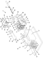
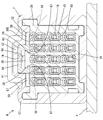
- FIG. 1 is a perspective view of the disassembled state of the female connector (connector) detached from the male connector in the first embodiment as viewed diagonally upward and forward.
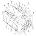
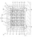
- FIG. 2 is a perspective view of a state in which the movable member and the release member are attached to the female side housing (housing) as viewed diagonally from above and behind.
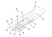
- FIG. 3 is a perspective view of the release member viewed from diagonally below and rearward.
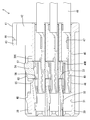
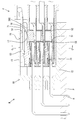
- FIG. 4 is a side sectional view showing a state in which a movable member is attached to a female side housing (housing) at a temporary locking position and a female terminal fitting (terminal fitting) is inserted into the female side housing.
- FIG. 1 is a perspective view of the disassembled state of the female connector (connector) detached from the male connector in the first embodiment as viewed diagonally upward and forward.
- FIG. 2 is a perspective view of a state in which the movable member and the release member are attached to the female side housing (housing) as
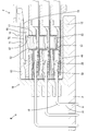
- FIG. 5 is a side sectional view showing a state in which the female terminal fitting is inserted into the female side housing and the movable member is displaced to the locked position.
- FIG. 6 is a side sectional view showing a state in which the female terminal fitting and the male terminal fitting (counterpart terminal) are not in contact with each other in the process of fitting the female connector and the male connector.
- FIG. 7 is a cross-sectional view taken along the line AA of FIG.
- FIG. 8 is a cross-sectional view taken along the line BB of FIG.
- FIG. 9 shows a state in which the movable member is displaced to the release position during the mating process of the female connector and the male connector, and the elastic contact piece of the female terminal fitting is elastically deformed in the direction away from the male terminal fitting.
- FIG. 10 is a cross-sectional view taken along the line CC of FIG.
- FIG. 11 is a side sectional view showing a locked state in which the female connector and the male connector are fitted, the lock function unit is locked to the male housing (the mating housing), and both connectors are restricted from being detached.
- FIG. 12 is a side sectional view showing an unlocked state in which the unlocking member is operated to dissociate the lock function portion from the male housing.
- the connectors of this disclosure are (1) A housing fitted to the mating housing and A lock function unit provided on the housing and locking the housing and the mating housing in a fitted state by locking the mating housing. It is a separate part from the housing, and includes a release member that can be attached to and detached from the housing. The release member can be displaced so as to dissociate the lock function portion from the mating housing in a state of being attached to the housing.
- the lock function portion when the mated housing and the mating housing are separated from each other, the lock function portion is displaced so as to be dissociated from the mating housing by operating the release member attached to the housing. .. Since it is possible to select the attachment / detachment of the release member to / from the housing according to the detachment frequency, only one type of housing is required. According to the present disclosure, the cost of the mold can be reduced as compared with the case of manufacturing two types of housings.
- the release member has a mounting portion to be attached to the housing and an arm portion that extends cantilevered from the mounting portion and comes into contact with the lock function portion, and the extending end portion of the arm portion.
- the lock function unit is an operation unit for displacement. According to this configuration, the lock function unit can be dissociated from the mating housing by the action of the lever by applying a small operating force to the operation unit.
- the lock function portion is formed on a movable member that is separate from the housing, and the movable member projects the lock function portion from the outer surface of the housing and locks the lock function portion to the mating housing. It is preferable that the lock position can be displaced between the lock position and the release position where the lock function portion is retracted to the inner side of the housing from the lock position and the lock function portion is dissociated from the mating housing. According to this configuration, the shape of the housing can be simplified and, by extension, the mold cost of the housing can be reduced as compared with the case where the lock function portion is integrally formed with the housing.
- the release member is attached so as to face the outer surface of the housing so as to cover a part of the lock function portion. According to this configuration, if the release member is pushed so as to approach the outer surface of the housing, the movable member can be displaced toward the release position side and the lock function portion can be dissociated from the mating housing.
- the lock function portion has a shape elongated in the width direction intersecting the fitting direction of the housing with respect to the mating housing, and the release member is a central portion of the lock function portion in the width direction. It is preferable that it covers only the shape. According to this configuration, the size of the release member in the width direction can be reduced. Further, during the unlocking operation, the unlocking member comes into contact with the central portion in the width direction of the locking function portion, so that the movable member can be displaced to the unlocking position side without tilting.
- the movable member is formed with a retaining portion for retaining the terminal fitting inserted into the housing when the movable member is in the locked position.
- the movable member has a function of locking the housing and the mating housing in a fitted state and a function of a retainer for holding out the terminal fitting. Therefore, the number of parts can be reduced as compared with the case where the retainer is provided separately from the movable member.
- the movable member can be displaced to a temporary locking position that allows insertion of the terminal fitting into the housing, and the release member has the movable member when the movable member is in the temporary locking position. It is preferable that an interference portion for restricting the attachment of the release member to the housing is formed by interfering with the housing. According to this configuration, it is possible to detect whether the movable member is in the temporary locking position or the locking position based on whether or not the releasing member can be attached to the housing.
- a terminal fitting is inserted into the housing, and the terminal fitting has an elastic contact piece that elastically contacts the mating terminal attached to the mating housing, and the movable member is elastic. It has a pressing portion that faces the contact piece, and when the movable member is in the release position, the elastic contact piece is elastically deformed so as to move away from the mating terminal by being pressed by the pressing portion. When the movable member is in the locked position, it is preferable that the elastic contact piece is released from the pressing of the pressing portion.
- the movable member when connecting the terminal fitting and the mating terminal, the movable member is displaced to the release position, and the elastic contact piece is elastically displaced in the direction away from the mating bracket.
- the fitting resistance caused by the sliding resistance between the mating terminal and the elastic contact piece can be avoided or reduced.
- the elastic contact piece released from the pressing of the pressing portion elastically contacts the mating terminal. Therefore, even if the number of poles of the terminal fitting is large, the mating terminal and the terminal fitting can be connected with a small operating force without using the boosting mechanism by the lever.
- the movable member is formed with an elastic flexure portion that elastically deforms when the movable member is displaced to the release position, and the movable member is moved from the release position by the elastic restoring force of the elastic flexure portion. It is preferable to apply an urging force in the direction of displacement to the lock position. According to this configuration, since the movable member is held in the locked position by the elastic restoring force of the elastic flexing portion, the locked state by the movable member can be maintained without using another member.
- Example 1 Example 1 that embodies the present disclosure will be described with reference to FIGS. 1 to 12. It should be noted that the present invention is not limited to these examples, and is indicated by the scope of claims, and is intended to include all modifications within the meaning and scope equivalent to the scope of claims.
- the front-back direction is defined as the front on the left side in FIGS. 4 to 6, 9, 11, and 12.
- the directions appearing in FIGS. 1 to 12 are defined as upward and downward as they are.
- the directions appearing in FIGS. 7, 8 and 10 are defined as left and right as they are.
- the female connector F of this embodiment is fitted to the male connector M.
- the male connector M has a male housing 10 mounted on the surface (upper surface) of the circuit board P, and a plurality of male terminal fittings 18 attached to the male housing 10. It is called a board connector.
- the female housing 30 has a wall-shaped terminal holding portion 11 that penetrates the male terminal fitting 18, and a square tubular hood portion 12 that protrudes from the outer peripheral edge of the terminal holding portion 11 toward the female connector F side. ..
- the upper wall portion 13 of the hood portion 12 is formed with a relief recess 14 in which the inner surface (lower surface) of the upper wall portion 13 is recessed.
- the relief recess 14 is arranged in the central portion in the left-right direction, and extends in the front-rear direction from the tip end (open end) of the hood portion 12 to the back end.
- An operation hole 15 in the form of penetrating the upper wall portion 13 is formed in a region of the upper wall portion 13 in which the relief recess 14 is formed.
- the operation hole 15 is arranged at a position slightly behind the tip of the hood portion 12.
- a pair of left and right locking portions 16 are formed on the upper wall portion 13 of the hood portion 12.
- the pair of locking locking portions 16 are arranged at portions of the upper wall portion 13 adjacent to the left and right sides of the relief recess 14 in a positional relationship spaced apart in the left-right direction.
- the locking locking portion 16 is arranged at the opening edge portion (tip portion) of the hood portion 12 in the front-rear direction, and has a locking surface 17 facing the inner side of the hood portion 12.
- the locking locking portion 16 is arranged so as to be adjacent to the front of the operation hole 15 (the opening end side of the hood portion 12).
- the pair of locking locking portions 16 are arranged at positions lower than the lower surface of the relief recess 14.
- the male terminal fitting 18 is an elongated metal rod bent into an L shape.
- the board connection portion 19 of the male terminal fitting 18 is exposed to the outside of the terminal holding portion 11 and is connected to the circuit board P in a state of being inserted into the through hole H.
- the tab 20 of the male terminal fitting 18 projects from the terminal holding portion 11 into the hood portion 12 and is connected to the female terminal fitting 45 described later.
- the female side connector F includes a female side housing 30 made of synthetic resin, a plurality of female terminal fittings 45, a movable member 52 made of synthetic resin, and a release member 63.
- the female housing 30 has a block shape as a whole. When both connectors F and M are fitted, the female housing 30 is housed in the hood portion 12.
- a plurality of terminal accommodating chambers 31 are formed in the female housing 30 so as to penetrate the female housing 30 in the front-rear direction.
- the plurality of terminal accommodating chambers 31 are arranged so as to be aligned in the vertical direction and the horizontal direction.
- An elastically deformable lance 32 is formed at the front end of the terminal accommodating chamber 31.
- the female side housing 30 has a storage space 33. As shown in FIG. 1, the accommodation space 33 opens to the outer surface 30S (upper surface) of the female housing 30 and both the left and right side surfaces, and communicates with all the terminal accommodation chambers 31.
- the accommodation space 33 is arranged at the center of the female housing 30 (position behind the lance 32) in the front-rear direction (direction orthogonal to the insertion / removal direction of the female terminal fitting 45 with respect to the female housing 30).
- a pair of left and right temporary locking portions 34 and a pair of left and right main locking portions 35 are formed on the left and right outer surfaces of the female housing 30.
- the temporary locking portion 34 and the main locking portion 35 are arranged in front of the accommodation space 33.
- the main locking portion 35 is arranged below the temporary locking portion 34.
- the temporary locking portion 34 exerts a function of holding the movable member 52 at the temporary locking position.
- the locking portion 35 exerts a function of holding the movable member 52 at the locked position.
- a pair of left and right expansion portions 36 are formed on both the left and right outer surfaces of the female side housing 30.
- the expanding portion 36 is arranged at a position below the main locking portion 35.
- the expansion portion 36 has a shape elongated in the front-rear direction over the front end side region of the accommodation space 33 and the region in front of the accommodation space 33.
- the front end side portion of the expansion portion 36 is arranged in the same region as the temporary locking portion 34 and the main locking portion 35 in the front-rear direction.
- the side surface of the expansion portion 36 is an expansion surface 37 that is oblique to the vertical direction when the female side housing 30 is viewed from the front.
- the expanding surface 37 is inclined downward so as to move away from the outer surface of the female housing 30.
- a pedestal portion 38 for attaching the movable member 52 is integrally formed on the outer surface 30S of the female side housing 30.
- the pedestal portion 38 is arranged at the front end portion of the female side housing 30 in the front-rear direction, and is arranged at the central portion of the female side housing 30 in the left-right direction (width direction).
- a pair of left and right guide portions 39 extending in the front-rear direction and projecting in a rib shape are formed on the left and right side edges of the pedestal portion 38.
- a retaining protrusion 40 is formed on the upper surface of the pedestal portion 38.
- a protective portion 41 is formed on the outer surface 30S of the female side housing 30.
- the protective portion 41 is arranged at the rear end portion of the female side housing 30, and has a pair of symmetrical protective wall portions 42 and a connecting portion 43.
- the protective wall portion 42 rises upward from the outer surface 30S of the female side housing 30.
- the connecting portion 43 is elongated in the left-right direction, and connects the front ends of the upper end edges of both the left and right protective wall portions 42.
- a notch 44 is formed in a region of the upper surface of the protective portion 41 behind the connecting portion 43. The notch 44 is sandwiched between the left and right protective wall portions 42 and is opened to the rear of the protective portion 41.
- the female terminal fitting 45 is formed by bending a metal plate material or the like to form an elongated shape in the front-rear direction as a whole. As shown in FIGS. 1 and 4, a square cylinder portion 46 is formed at the front end portion of the female terminal fitting 45. A crimping portion 47 is formed at the rear end portion of the female terminal fitting 45, and the crimping portion 47 is crimped to the front end portion of the electric wire 48.
- the female terminal fitting 45 is inserted into the terminal accommodating chamber 31 from the rear of the female housing 30, and is released by the locking action of the lance 32. When the female terminal fitting 45 is inserted into the normal position of the terminal accommodating chamber 31, the rear end edge portion 46R of the square tube portion 46 is positioned so as to be adjacent to the front of the front end of the accommodating space 33.
- the female terminal fitting 45 has an elastic contact piece 49 that elastically contacts the tab 20 of the male terminal fitting 18.
- the elastic contact piece 49 is folded back from the front end of the lower plate portion constituting the square tube portion 46 and extends in a cantilever shape.
- a contact portion 50 that makes point contact or line contact with the tab 20 is formed at a position slightly rearward of the front end of the elastic contact piece 49.
- the rear end portion (extending end portion) of the elastic contact piece 49 functions as a pressure receiving portion 51.
- Most of the elastic contact piece 49 except the pressure receiving portion 51 and including the contact portion 50 is housed in the square tube portion 46.
- the pressure receiving portion 51 projects rearward from the rear end of the square tube portion 46.
- the movable member 52 is an independent synthetic resin part separate from the female side housing 30. As shown in FIG. 1, the movable member 52 is a symmetrical single component having a main body portion 53 having a square front view shape when viewed from the front, a lock function portion 57, and a pair of elastic bending portions 61. is there.
- the main body 53 has a plurality of through holes 54 aligned in the vertical direction and the horizontal direction. In front view, the plurality of through holes 54 are aligned in the vertical direction and the horizontal direction.
- the alignment form of the through holes 54 is the same as the alignment form of the plurality of terminal accommodating chambers 31. As shown in FIG.
- each through hole 54 in the front surface of the main body portion 53 functions as a retaining portion 55.
- the front end portion on the upper surface of each through hole 54 functions as a pressing portion 56 facing downward.
- the pressing portion 56 and the retaining portion 55 are connected at a right angle.
- the lock function portion 57 protrudes upward from the upper wall portion 13 of the main body portion 53 and extends in the left-right direction.
- the central portion of the lock function portion 57 in the left-right direction functions as a receiving portion 58.
- the left and right ends of the lock function portion 57 function as lock portions 59.
- the pair of lock portions 59 are arranged so as to sandwich the receiving portion 58 from both the left and right sides.
- the receiving portion 58 and the pair of locking portions 59 are continuously connected.
- An induction surface 60 is formed on the upper surface of the lock function portion 57 so as to be lowered toward the front.
- the pair of elastic flexing portions 61 have a cantilevered shape extending forward from the front end edges of the left and right side wall portions of the main body portion 53.
- the pair of elastic flexing portions 61 have a rectangular plate shape and can be elastically deformed so as to expand each other.
- the lower end edge of the elastic flexure portion 61 has a locking edge portion protruding from the inner surface of the elastic flexure portion 61 (the surface facing the elastic flexure portion 61 on the other side). 62 is formed.
- the movable member 52 accommodates the main body 53 in the accommodation space 33 from above the female housing 30, and the female housing in a state where the pair of elastic flexing portions 61 are overlapped on the left and right outer surfaces of the female housing 30. It is attached to 30.
- the movable member 52 is a component having multiple functions, and when attached to the female side housing 30, it exhibits a retainer function, a fitting force reducing function, and a locking function.
- the retainer function detects the inserted state of the female terminal fitting 45 in the female housing 30 (terminal accommodating chamber 31) and retains the female terminal fitting 45 inserted in the female housing 30 (terminal accommodating chamber 31). Is.
- the fitting force reducing function is a function of reducing the fitting resistance caused by friction between the female terminal fitting 45 and the male terminal fitting 18 in the fitting process of both connectors F and M.
- the lock function is a function of locking both normally fitted connectors F and M (both housings 10 and 30) in a detachment restricted state.
- the movable member 52 attached to the female housing 30 has a temporary locking position (see FIG. 4), a locking position (see FIGS. 2, 5, 6, 8 and 11), and an unlocking position (see FIGS. 9, 10, 11). It is designed to be held in three positions (see 12).
- the temporary locking position is set to the highest position among the three positions.
- the movable member 52 is held at the temporary locking position by vertically sandwiching the locking edge portion 62 between the temporary locking portion 34 and the main locking portion 35.
- the movable member 52 held in the temporarily locked position is in a ready state in which the inserted state of the female terminal fitting 45 can be detected.
- the lock position is set lower than the temporary lock position and higher than the release position.
- the movable member 52 is held at the locked position by vertically sandwiching the locking edge portion 62 between the main locking portion 35 and the expanding surface 37.
- the movable member 52 held at the locked position can exhibit a function of retaining the female terminal fitting 45 and a function of locking both connectors F and M in the fitted state.
- the release position is set to the lowest position among the three positions.
- the movable member 52 at the release position loses the function of locking both connectors F and M in the fitted state, and exhibits the function of reducing the fitting resistance. Further, when the movable member 52 is in the release position, as shown in FIG. 10, the lower end portions of the pair of elastic flexing portions 61 are deformed by the expanding portion 36 so as to be curved outward in the left-right direction (width direction). Therefore, the elastic restoring force is stored in the elastic bending portion 61.
- the release member 63 is a component made of synthetic resin that is independent of the female side housing 30 and the movable member 52.
- the release member 63 is a component for performing an operation of releasing the locked state of both connectors F and M (both housings 10 and 30) locked in the fitted state by the movable member 52.
- the release member 63 is a plate-shaped component elongated in the front-rear direction as a whole.
- the release member 63 has a mounting portion 64, an arm portion 71, and an operating portion 74, and has a symmetrical shape.
- the mounting portion 64 is formed at the front end portion of the release member 63.
- the mounting portion 64 includes an upper plate portion 65 whose plate thickness direction is directed in the vertical direction, left and right side plate portions 66, a pair of left and right sliding contact portions 67, a hooking portion 68, and a front stop portion 69.
- the left and right side plate portions 66 extend downward from the left and right side edge portions of the upper plate portion 65.
- the pair of left and right sliding contact portions 67 project inward (center side in the left-right direction) from the lower end edges of the left and right side plate portions 66 in a rib shape.
- the hook portion 68 has a form protruding downward from the rear end edge of the upper plate portion 65.
- the front stop portion 69 is connected to the front end edge of the upper plate portion 65 and the front end edges of the left and right side edges.
- the front stop portion 69 is opened with a die-cutting hole 70 formed when the hook portion 68 is molded.
- the arm portion 71 is aligned with the rear end edge of the upper plate portion 65 and extends rearward from the upper plate portion 65 in a cantilever shape.
- a pair of left and right contact portions 72 are formed on the lower surface of the arm portion 71.
- the contact portion 72 protrudes downward from the left and right side edges of the arm portion 71 and extends in the front-rear direction.
- the forming region of the contact portion 72 in the front-rear direction is a range extending from the rear end of the side plate portion 66 of the mounting portion 64 to the central portion in the front-rear direction of the arm portion 71.
- An interference portion 73 is formed on the lower surface of the arm portion 71.
- the interference portion 73 is formed from the central portion in the front-rear direction of the arm portion 71 to the rear end of the arm portion 71.
- the front end side region of the interference portion 73 is arranged on the left and right side edges of the arm portion 71, and is connected to the rear end of the contact portion 72.
- the rear end portion of the interference portion 73 extends over the entire width of the arm portion 71.
- the lower surface of the interference portion 73 is inclined so as to be lowered toward the front.
- the operation portion 74 is formed at the rear end portion of the arm portion 71.
- the operation unit 74 has a shape protruding stepwise from the upper surface of the arm unit 71.
- the stepped protrusion makes it difficult for the finger on the operation unit 74 to come off rearward.
- the operation unit 74 can apply a downward pressing force from above the release member 63.
- the release member 63 is removable from the female housing 30, but the necessity of attachment / detachment can be arbitrarily selected according to the frequency with which both connectors F and M are detached. That is, when the lock by the movable member 52 is frequently released, the release member 63 is attached to the female side housing 30. When the lock by the movable member 52 is released infrequently, both connectors F and M are fitted without attaching the release member 63 to the female side housing 30.
- the movable member 52 is attached to the female side housing 30 and held at the temporary locking position.
- the height of the through hole 54 matches the height of the terminal accommodating chamber 31, and the retaining portion 55 retracts above the insertion path of the female terminal fitting 45 with respect to the terminal accommodating chamber 31. .. Therefore, the female terminal fitting 45 can be inserted and removed from the terminal accommodating chamber 31.
- the female terminal fitting 45 is inserted into the terminal accommodating chamber 31 while the movable member 52 is held at the temporarily locked position.
- the movable member 52 If there is a female terminal fitting 45 that has not been inserted to the normal position when all the female terminal fittings 45 have been inserted, the movable member 52 is pushed down from the temporary locking position to the locking position. At this time, the pressing portion 56 hits the upper surface of the square cylinder portion 46. Therefore, the movable member 52 cannot be pushed down to the locked position. Therefore, based on whether or not the movable member 52 in the temporarily locked position can be pushed into the locked position, the female terminal fitting 45 is in the inserted state (that is, all the female terminal fittings 45 are normally inserted or semi-inserted). (Whether the female terminal fitting 45 is present) can be detected.
- the release member 63 is attached to the female side housing 30.
- the mounting portion 64 is brought closer to the pedestal portion 38 from the front of the female side housing 30 while covering the pedestal portion 38 with the arm portion 71 from above.
- the hook portion 68 is brought into sliding contact with the upper surface of the pedestal portion 38, and the side plate portion 66 and the sliding contact portion 67 are brought into sliding contact with the side surface and the lower surface of the guide portion 39.
- the release member 63 is attached in a state where the relative displacement in the vertical direction and the horizontal direction is restricted with respect to the pedestal portion 38 and is held in a constant posture.
- the hooking portion 68 gets over the retaining protrusion 40 and comes into contact with the retaining protrusion 40 from the rear, and the front stop portion 69 is a pedestal. It contacts the portion 38 from the front. By this contact action, the release member 63 is held in a state where the movement in the front-rear direction is restricted with respect to the pedestal portion 38 (female side housing 30).
- the lower surface of the contact portion 72 faces the receiving portion 58 of the lock function portion 57 in a positional relationship close to each other from above.
- the pair of left and right lock portions 59 are exposed upward on both the left and right sides of the release member 63.
- the operating portion 74 is housed in the protective portion 41, is sandwiched between the left and right protective wall portions 42, and is located below the connecting portion 43.
- the cutout portion 44 is formed on the upper surface portion of the protective portion 41, it is possible to accommodate a finger between the left and right protective wall portions 42 and push the operation portion 74 from above with the finger. is there.
- the release member 63 when the release member 63 is to be attached to the pedestal portion 38 while the movable member 52 is in the temporarily locked position, the hook portion 68 comes into contact with the upper surface of the pedestal portion 38 and becomes the side plate portion 66. Immediately after the sliding contact portion 67 comes into contact with the side surface and the lower surface of the guide portion 39 and the release member 63 is held in a constant mounting posture, the lower surface of the interference portion 73 of the release member 63 is subjected to the receiving portion 58 (lock function portion 57). ) Interferes. If the release member 63 is assembled in this state, the sliding friction between the inclined lower surface of the interference portion 73 and the receiving portion 58 increases, so that the resistance to the assembly increases. Therefore, it becomes difficult to proceed with the attachment of the release member 63.
- the hook portion 68 abuts on the retaining protrusion 40, so that the assembly resistance increases at once. Therefore, even if the assembly is forcibly proceeded, it becomes difficult to attach the release member 63 before the normal assembly state is reached. Therefore, there is no possibility that the release member 63 will be attached to the female side housing 30 while the movable member 52 is in the temporarily locked position. Further, it is possible to detect whether or not the movable member 52 has moved to the lock position based on whether or not the release member 63 can be attached.
- the movable member 52 at the temporarily locked position can be pushed down to the locked position by the inclined lower surface of the interference portion 73. .. In this case, a considerably large force is required, but as soon as the assembly of the release member 63 is completed, the movable member 52 is held in the locked position.
- the fitting resistance between both connectors F and M is reduced.
- the release member 63 is housed in the relief recess 14, so that the release member 63 is not deformed or displaced by contact with the hood portion 12.
- the locking edge portion 62 of the elastic flexure portion 61 is elastically deformed so as to expand by sliding contact with the expansion portion 36. Be done.
- the elastic restoring force is stored in the elastic flexing portion 61, so that the movable member 52 tends to move to the lock position side.
- the movable member 52 is given a returning force to the lock position side by the elastic restoring force of the elastic contact piece 49.
- the lock portion 59 (lock function portion 57) passes through the lock locking portion 16, so that the movable member 52 elastically returns from the release position to the lock position. To do.
- the lock function portion 57 is displaced so as to protrude from the outer surface 30S of the female side housing 30, and the left and right lock portions 59 are displaced from the locking surface 17 of the left and right lock locking portions 16. Lock to.
- both connectors F and M are locked in a state in which disconnection is restricted.
- the pressing portion 56 dissociates from the pressure receiving portion 51, so that the elastic contact piece 49 elastically returns in the direction approaching the tab 20, and the tab 20 and the elastic contact piece 49 are located. It is connected by the contact pressure of the period.
- the release member 63 does not move from the start of fitting of both connectors F and M to the completion of fitting.
- the operation portion 74 of the release member 63 When disengaging both connectors F and M in the fitted state, the operation portion 74 of the release member 63 is pushed and operated to displace the arm portion 71 so as to approach the outer surface 30S of the female side housing 30. At this time, the release member 63 is elastically deformed. By pushing the operation unit 74, the contact portion 72 of the release member 63 presses the receiving portion 58, so that the movable member 52 at the lock position is pushed down to the release position. When the movable member 52 moves to the release position, the lock function portion 57 is housed in the female side housing 30 (inside the accommodation space 33), and the lock portion 59 is dissociated from the lock locking portion 16 (locking surface 17). As a result, the locked state by the lock portion 59 is released, so that the connectors F and M (both housings 10 and 30) may be separated while maintaining the unlocked state.
- both connectors F and M both housings 10 and 30
- both connectors F and M are detached while maintaining the state in which the movable member 52 is pushed to the release position with a jig, a tool, or a finger.
- the detachment of both connectors F and M is completed by removing the jig, the tool or the finger from the movable member 52.
- the female side connector F of the first embodiment includes a female side housing 30 fitted to the male side housing 10, a lock function portion 57 provided in the female side housing 30, and a release member 63.
- the lock function portion 57 locks the female side housing 30 and the male side housing 10 in a fitted state by locking the male side housing 10.
- the release member 63 is a separate part from the female housing 30, and is removable from the female housing 30. The release member 63 can be displaced so as to dissociate the lock function portion 57 from the male housing 10 when the release member 63 is attached to the female housing 30.
- the lock function portion 57 is dissected from the male housing 10 by operating the release member 63 attached to the female housing 30. Displace. Since it is possible to select the attachment / detachment of the release member 63 to / from the female side housing 30 according to the detachment frequency, only one type of female side housing 30 is required. Therefore, according to the female side connector F of this embodiment, the cost of the mold can be reduced as compared with the case of manufacturing the two types of female side housings 30.
- the release member 63 has a mounting portion 64 that is attached to the female housing 30, and an arm portion 71 that extends cantilevered from the mounting portion 64 and abuts on the lock function portion 57.
- the extending end portion of the arm portion 71 is an operating portion 74 for displacing the lock function portion 57 in the unlocking direction.
- the operation unit 74 When the operation unit 74 is operated, the arm unit 71 is displaced so as to tilt its posture with the mounting unit 64 as a fulcrum, and pushes and moves the lock function unit 57.
- the portion of the arm portion 71 that comes into contact with the lock function portion 57 is closer to the mounting portion 64 than the operating portion 74. Therefore, by simply applying a small operating force to the operating unit 74, the lock function unit 57 can be moved and dissociated from the male housing 10 by the action of the lever.
- the lock function portion 57 is formed on a movable member 52 that is separate from the female side housing 30.
- the movable member 52 can be displaced between the lock position and the release position retracted to the inner side (inside the accommodation space 33) of the female housing 30 from the lock position.
- the lock function portion 57 protrudes from the outer surface 30S of the female housing 30 and is locked to the male housing 10.
- the lock function portion 57 dissociates from the male housing 10.
- the lock function portion 57 is formed on a movable member 52 that is separate from the female side housing 30, the shape of the female side housing 30 is as compared with the case where the lock function portion 57 is integrally formed with the female side housing 30. Can be simplified. Thereby, the mold cost of the female side housing 30 can be reduced.
- the release member 63 is attached so as to face the outer surface 30S of the female side housing 30 in a form of covering a part of the lock function portion 57 (only the receiving portion 58 in the center in the left-right direction). Therefore, if the release member 63 is pushed so as to approach the outer surface 30S of the female side housing 30, the movable member 52 can be displaced toward the release position side and the lock function portion 57 can be dissociated from the male side housing 10.
- the lock function portion 57 has a shape elongated in the width direction (left-right direction) intersecting the fitting direction of the female side housing 30 with respect to the male side housing 10, and the release member 63 is the center of the lock function portion 57 in the width direction. It is a form that covers only the portion (receiving portion 58). According to this configuration, the size of the release member 63 in the width direction can be reduced. Further, during the unlocking operation, the unlocking member 63 comes into contact with the central portion in the width direction of the locking function portion 57, so that the movable member 52 can be displaced to the unlocking position side without tilting.
- the movable member 52 is formed with a retaining portion 55.
- the retaining portion 55 retains the female terminal fitting 45 inserted into the female housing 30. That is, the movable member 52 has not only the function of locking the female side housing 30 and the male side housing 10 in the fitted state, but also the function of a retainer for retaining the female terminal fitting 45. Therefore, the female side connector F of the present embodiment can reduce the number of parts as compared with the case where the retainer is provided separately from the movable member 52.
- the movable member 52 can be displaced to a temporary locking position that allows the female terminal fitting 45 to be inserted into the female housing 30.
- the release member 63 is formed with an interference portion 73 that regulates the attachment of the release member 63 to the female housing 30 by interfering with the movable member 52 when the movable member 52 is in the temporarily locked position. According to this configuration, it is possible to detect whether the movable member 52 is in the temporary locking position or the locking position based on whether or not the releasing member 63 can be attached to the female side housing 30. ..
- the female terminal fitting 45 is inserted into the female housing 30.
- the female terminal fitting 45 has an elastic contact piece 49 that elastically contacts the male terminal fitting 18 attached to the male housing 10.
- the movable member 52 has a pressing portion 56 facing the elastic contact piece 49. When the movable member 52 is in the release position, the elastic contact piece 49 is elastically displaced in the direction away from the tab 20 of the male terminal fitting 18 by being pressed by the pressing portion 56. When the movable member 52 is in the locked position, the elastic contact piece 49 is released from the pressing of the pressing portion 56.
- the movable member 52 when connecting the female terminal fitting 45 and the male terminal fitting 18, the movable member 52 is displaced to the release position, and the elastic contact piece 49 is elastically displaced in the direction away from the male terminal fitting 18. Keep it. Thereby, the fitting resistance caused by the sliding resistance between the male terminal fitting 18 and the elastic contact piece 49 can be avoided or reduced.
- the elastic contact piece 49 released from the pressing of the pressing portion 56 elastically contacts the male terminal fitting 18. To do. Therefore, even if the number of poles of the female terminal fitting 45 is large, the male terminal fitting 18 and the female terminal fitting 45 can be connected with a small operating force without using the boosting mechanism by the lever.
- the movable member 52 is formed with an elastic flexible portion 61 that elastically deforms when the movable member 52 is displaced to the release position.
- the movable member 52 is given an urging force in the direction of displacement from the release position to the lock position by the elastic restoring force of the elastic flexure portion 61. According to this configuration, since the movable member 52 is held in the locked position by the elastic restoring force of the elastic flexing portion 61, the locked state by the movable member 52 can be maintained without using another member.
- the present invention is not limited to the examples described in the above description and drawings, but is shown by the scope of claims.
- the present invention includes meaning equivalent to the scope of claims and all modifications within the scope of claims, and is intended to include embodiments such as:
- the lock by the lock function portion is released by bringing the release member close to the outer surface of the housing, but the displacement direction of the release member at the time of unlocking is parallel to the outer surface of the housing. It may be in any direction.
- the unlocking member is pushed during the unlocking operation, but the unlocking member may be pulled to unlock the lock.
- the release member covers only the central portion in the width direction of the lock function portion, but the release member may cover both ends in the width direction of the lock function portion. In this case, the central portion of the lock function portion in the width direction is locked to the mating housing.
- the release member is cantilevered backward, but the release member may be cantilevered forward or sideways.
- the release member is attached to the housing in a cantilevered manner, but the release member may be attached to the housing in a cantilever shape.
- the mounting portion of the release member is fixed to the housing, and the release member is elastically deformed to dissociate the lock function portion from the mating housing.
- the release member has a shaft with respect to the housing.
- the movable member when the movable member is in the temporary locking position, the interference portion of the release member interferes with the movable member, but the release member may have no interference portion. In this case, the release member can be attached to the housing even when the movable member is in the temporarily locked position.
- the movable member also has a function as a retainer for holding out the terminal fitting, but the movable member may not have a function as a retainer.
- the lock function portion is formed on a movable member separate from the housing, but the lock function portion may be integrally formed on the housing.
- the lock function portion is displaced from the outer surface of the housing in the direction of protrusion to lock the mating housing, but the lock function portion is displaced along the outer surface of the housing. As a result, it may be locked to the housing on the other side.
- the movable member has a function of avoiding or reducing the fitting resistance caused by the sliding resistance between the terminal fitting and the mating terminal, but the movable member avoids the fitting resistance. Alternatively, it may not have a function of reducing.
- Female terminal metal fittings (terminal metal fittings) 46 Square tube 46R ... Rear edge edge 47 of the square tube 47 ... Crimping part 48 ... Electric wire 49 ... Elastic contact piece 50 ... Contact 51 ... Pressure receiving part 52 ... Movable member 53 ... Main body 54 ... Through hole 55 ... Extraction Stopping part 56 ... Pressing part 57 ... Locking function part 58 ... Receiving part 59 ... Locking part 60 ... Guide surface 61 ... Elastic bending part 62 ... Locking edge part 63 ... Release member 64 ... Mounting part 65 ... Top plate part 66 ... Side plate Part 67 ... Sliding contact part 68 ... Hooking part 69 ... Front stop part 70 ... Die-cutting hole 71 ... Arm part 72 ... Pad part 73 ... Interference part 74 ... Operation part F ... Female side connector (connector) H ... Through hole M ... Male side connector P ... Circuit board
Abstract
コストを低減する。 雌側コネクタ(F)は、雄側ハウジング(10)に嵌合される雌側ハウジング(30)と、雌側ハウジング(30)に設けられ、雄側ハウジング(10)に係止することで雌側ハウジング(30)と雄側ハウジング(10)を嵌合状態にロックするロック機能部(57)と、雌側ハウジング(30)とは別体の部品であり、雌側ハウジング(30)に対して着脱可能な解除部材(63)とを備え、解除部材(63)は、雌側ハウジング(30)に取り付けた状態において、ロック機能部(57)を雄側ハウジング(10)から解離させるように変位させることが可能である。
Description
本開示は、コネクタに関するものである。
特許文献1には、ハウジングの外面にロックアームが形成されたコネクタが開示されている。このコネクタを相手側コネクタに嵌合した状態では、ロックアームの係止突起が相手側コネクタの係止部に係止することによって、両コネクタが嵌合状態にロックされる。嵌合状態の両コネクタを離脱する際には、ロックアームの解除操作部(連結部)を指で押し操作することによって、ロックアームを弾性変形させて係止突起を係止部から解離させる。この操作によって、ロックアームによるロック状態が解除されるので、両コネクタを離脱させることができる。
上記コネクタは、治具を用いることなく解除操作部を指で押し操作するだけで、両コネクタのロックを解除することができるので、ロック解除の作業性が良い。したがって、このコネクタは、相手側コネクタと嵌合した後に離脱する頻度が多い場合に有用である。しかし、離脱頻度の少ない場合は、解除操作部が有効活用されない。この対策としては、解除操作部が形成されたハウジングと解除部材が形成されていないハウジングとを用意し、この2つのタイプのハウジングを離脱頻度に応じて使い分けることが考えられる。しかし、2種類のハウジングを製造すると、金型コストが高くなるという問題がある。
本開示のコネクタは、上記のような事情に基づいて完成されたものであって、コストを低減することを目的とする。
本開示のコネクタは、
相手側ハウジングに嵌合されるハウジングと、
前記ハウジングに設けられ、前記相手側ハウジングに係止することで前記ハウジングと前記相手側ハウジングを嵌合状態にロックするロック機能部と、
前記ハウジングとは別体の部品であり、前記ハウジングに対して着脱可能な解除部材とを備え、
前記解除部材は、前記ハウジングに装着した状態において、前記ロック機能部を前記相手側ハウジングから解離させるように変位させることが可能である。
相手側ハウジングに嵌合されるハウジングと、
前記ハウジングに設けられ、前記相手側ハウジングに係止することで前記ハウジングと前記相手側ハウジングを嵌合状態にロックするロック機能部と、
前記ハウジングとは別体の部品であり、前記ハウジングに対して着脱可能な解除部材とを備え、
前記解除部材は、前記ハウジングに装着した状態において、前記ロック機能部を前記相手側ハウジングから解離させるように変位させることが可能である。
本開示によれば、コストを低減することができる。
[本開示の実施形態の説明]
最初に本開示の実施形態を列記して説明する。
本開示のコネクタは、
(1)相手側ハウジングに嵌合されるハウジングと、
前記ハウジングに設けられ、前記相手側ハウジングに係止することで前記ハウジングと前記相手側ハウジングを嵌合状態にロックするロック機能部と、
前記ハウジングとは別体の部品であり、前記ハウジングに対して着脱可能な解除部材とを備え、
前記解除部材は、前記ハウジングに装着した状態において、前記ロック機能部を前記相手側ハウジングから解離させるように変位させることが可能である。
最初に本開示の実施形態を列記して説明する。
本開示のコネクタは、
(1)相手側ハウジングに嵌合されるハウジングと、
前記ハウジングに設けられ、前記相手側ハウジングに係止することで前記ハウジングと前記相手側ハウジングを嵌合状態にロックするロック機能部と、
前記ハウジングとは別体の部品であり、前記ハウジングに対して着脱可能な解除部材とを備え、
前記解除部材は、前記ハウジングに装着した状態において、前記ロック機能部を前記相手側ハウジングから解離させるように変位させることが可能である。
本開示の構成によれば、嵌合状態のハウジングと相手側ハウジングを離脱させる際には、ハウジングに装着した解除部材を操作することによって、ロック機能部を相手側ハウジングから解離させるように変位させる。離脱頻度に応じてハウジングに対する解除部材の着脱を選択することができるので、ハウジングは1種類だけで済む。本開示によれば、2種類のハウジングを製造する場合に比べて金型のコストを低減できる。
(2)前記解除部材は、前記ハウジングに取り付けられる取付部と、前記取付部から片持ち状に延出して前記ロック機能部に当接するアーム部とを有し、前記アーム部の延出端部が、前記ロック機能部を変位させるための操作部となっていることが好ましい。この構成によれば、テコの作用によって、小さい操作力を操作部に加えるだけで、ロック機能部を相手側ハウジングから解離させることができる。
(3)前記ロック機能部が、前記ハウジングとは別体の可動部材に形成されており、前記可動部材は、前記ロック機能部を前記ハウジングの外面から突出させて前記相手側ハウジングに係止させるロック位置と、前記ロック位置よりも前記ハウジングの内部側へ退避して前記ロック機能部を前記相手側ハウジングから解離させる解除位置との間で変位可能であることが好ましい。この構成によれば、ロック機能部をハウジングに一体に形成する場合に比べると、ハウジングの形状を簡素化することができ、ひいては、ハウジングの金型コストを低減することができる。
(4)前記解除部材は、前記ロック機能部の一部を覆う形態で前記ハウジングの前記外面と対向するように取り付けられることが好ましい。この構成によれば、解除部材をハウジングの外面に接近させるように押し操作すれば、可動部材を解除位置側へ変位させてロック機能部を相手側ハウジングから解離させることができる。
(5)前記ロック機能部は、前記相手側ハウジングに対する前記ハウジングの嵌合方向と交差する幅方向に細長く延びた形状であり、前記解除部材は、前記ロック機能部のうち前記幅方向の中央部のみを覆う形態であることが好ましい。この構成によれば、幅方向における解除部材の寸法を小さくすることができる。また、ロック解除操作の際には、解除部材がロック機能部の幅方向中央部に当接するので、可動部材を傾かせることなく解除位置側へ変位させることができる。
(6)前記可動部材には、前記可動部材が前記ロック位置にあるときに前記ハウジングに挿入された前記端子金具を抜止めする抜止め部が形成されていることが好ましい。この構成によれば、可動部材は、ハウジングと相手側ハウジングを嵌合状態にロックする機能と、端子金具を抜止めするためのリテーナとしての機能を兼ね備えている。したがって、可動部材とは別にリテーナを設ける場合に比べると、部品点数を削減できる。
(7)前記可動部材は、前記ハウジングに対する端子金具の挿入を許容する仮係止位置へ変位可能であり、前記解除部材には、前記可動部材が前記仮係止位置にあるときに前記可動部材と干渉することで、前記ハウジングに対する前記解除部材の取り付けを規制する干渉部が形成されていることが好ましい。この構成によれば、解除部材をハウジングに取り付けることができるか否かに基づいて、可動部材が仮係止位置とロック位置のいずれの位置にあるかを検知することができる。
(8)前記ハウジングには端子金具が挿入され、前記端子金具は、前記相手側ハウジングに取り付けた相手側端子に対して弾性的に接触する弾性接触片を有し、前記可動部材は、前記弾性接触片と対向する押圧部を有しており、前記可動部材が前記解除位置にあるときには、前記弾性接触片が前記押圧部で押圧されることによって前記相手側端子から遠ざかるように弾性変形し、前記可動部材が前記ロック位置にあるときには、前記弾性接触片が前記押圧部の押圧から解放されることが好ましい。
この構成によれば、端子金具と相手側端子を接続する際には、可動部材を解除位置へ変位させ、弾性接触片を相手側金具から遠ざかる方向へ弾性的に変位させておく。これによって、相手側端子と弾性接触片との間の摺動抵抗に起因する嵌合抵抗を回避又は低減できる。ハウジングと相手側ハウジングが嵌合して可動部材がロック位置へ変位すると、押圧部の押圧から解放された弾性接触片が、相手側端子に対して弾性的に接触する。したがって、端子金具の極数が多くても、レバーによる倍力機構を用いることなく小さい操作力で相手側端子と端子金具の接続を行うことができる。
(9)前記可動部材には、前記可動部材が前記解除位置へ変位したときに弾性変形する弾性撓み部が形成され、前記可動部材は、前記弾性撓み部の弾性復元力によって前記解除位置から前記ロック位置へ変位する方向の付勢力を付与されることが好ましい。この構成によれば、可動部材は弾性撓み部の弾性復元力によってロック位置に保持されるので、他部材を用いなくても、可動部材によるロック状態を保つことができる。
[本開示の実施形態の詳細]
[実施例1]
本開示を具体化した実施例1を、図1~図12を参照して説明する。なお、本発明はこれらの例示に限定されるものではなく、特許請求の範囲によって示され、特許請求の範囲と均等の意味および範囲内でのすべての変更が含まれることが意図される。
[実施例1]
本開示を具体化した実施例1を、図1~図12を参照して説明する。なお、本発明はこれらの例示に限定されるものではなく、特許請求の範囲によって示され、特許請求の範囲と均等の意味および範囲内でのすべての変更が含まれることが意図される。
本実施例1において、前後の方向については、図4~6,9,11,12における左方を前方と定義する。上下の方向については、図1~12にあらわれる向きを、そのまま上方、下方と定義する。左右の方向については、図7,8,10にあらわれる向きを、そのまま左方、右方と定義する。
本実施例の雌側コネクタFは、雄側コネクタMに嵌合されるものである。図1に示すように、雄側コネクタMは、回路基板Pの表面(上面)に実装される雄側ハウジング10と、雄側ハウジング10に取り付けた複数本の雄端子金具18とを有し、基板用コネクタと称されるものである。雌側ハウジング30は、雄端子金具18を貫通させる壁状の端子保持部11と、端子保持部11の外周縁から雌側コネクタF側に向かって突出した角筒状のフード部12とを有する。
図1,7に示すように、フード部12の上壁部13には、上壁部13の内面(下面)を凹ませた形態の逃がし凹部14が形成されている。逃がし凹部14は、左右方向における中央部に配され、フード部12の先端(開口端)から奥端まで前後方向に延びている。上壁部13のうち逃がし凹部14が形成されている領域には、上壁部13を貫通した形態の操作孔15が形成されている。操作孔15は、フード部12の先端よりも少し後方の位置に配されている。
図6,7に示すように、フード部12の上壁部13には、左右一対のロック用係止部16が形成されている。一対のロック用係止部16は、左右方向に間隔を空けた位置関係で、上壁部13のうち逃がし凹部14の左右両側に隣接する部位に配されている。図6に示すように、ロック用係止部16は、前後方向においてはフード部12の開口縁部(先端部)に配され、フード部12の奥側に面する係止面17を有する。フード部12を側方から見た側面視において、ロック用係止部16は、操作孔15の前方(フード部12の開口端側)に隣り合うように配されている。上下方向においては、一対のロック用係止部16は、逃がし凹部14の下面よりも低い位置に配されている。
図1,6に示すように、雄端子金具18は、細長い金属棒材をL字形に屈曲したものである。雄端子金具18の基板接続部19は、端子保持部11の外部に露出し、スルーホールHに挿入された状態で回路基板Pに接続されている。雄端子金具18のタブ20は、端子保持部11からフード部12内へ突出しており、後述する雌端子金具45に接続される。
雌側コネクタFは、合成樹脂製の雌側ハウジング30と、複数の雌端子金具45と、合成樹脂製の可動部材52と、解除部材63とを備えて構成されている。図1,2に示すように、雌側ハウジング30は、全体としてブロック状をなす。両コネクタF,Mが嵌合する際には、フード部12内に雌側ハウジング30が収容される。図4に示すように、雌側ハウジング30内には、雌側ハウジング30を前後方向に貫通した形態の複数の端子収容室31が形成されている。複数の端子収容室31は、上下方向及び左右方向に整列して配置されている。端子収容室31の前端部には、弾性変形可能なランス32が形成されている。
雌側ハウジング30は収容空間33を有している。図1に示すように、収容空間33は、雌側ハウジング30の外面30S(上面)と左右両側面とに開口し、全ての端子収容室31と連通している。収容空間33は、前後方向(雌側ハウジング30に対する雌端子金具45の挿抜方向と直交する方向)において、雌側ハウジング30の中央部(ランス32よりも後方の位置)に配されている。
図1,8,10に示すように、雌側ハウジング30の左右両外側面には、左右一対の仮係止部34と、左右一対の本係止部35が形成されている。仮係止部34と本係止部35は、収容空間33の前方に配されている。本係止部35は仮係止部34の下方に配されている。仮係止部34は、可動部材52を仮係止位置に保持する機能を発揮する。本係止部35は、可動部材52をロック位置に保持する機能を発揮する。
雌側ハウジング30の左右両外側面には、左右一対の拡開部36が形成されている。拡開部36は、本係止部35よりも下方の位置に配されている。拡開部36は、収容空間33の前端側領域と収容空間33よりも前方の領域とにわたり、前後方向に細長く延びた形状である。拡開部36の前端側部位は、前後方向において仮係止部34及び本係止部35と同じ領域に配されている。拡開部36の側面は、雌側ハウジング30を前方から見た正面視において、上下方向に対して斜めをなす拡開面37となっている。拡開面37は、下方に向かって雌側ハウジング30の外側面から遠ざかるように傾斜している。
図1,4,7に示すように、雌側ハウジング30の外面30Sには、可動部材52を取り付けるための台座部38が一体に形成されている。台座部38は、前後方向においては雌側ハウジング30の前端部に配され、左右方向(幅方向)においては雌側ハウジング30の中央部に配されている。台座部38の左右両側縁部には、前後方向に延びてリブ状に突出した形態の左右一対のガイド部39が形成されている。台座部38の上面には抜止め突起40が形成されている。
図1,4に示すように、雌側ハウジング30の外面30Sには、保護部41が形成されている。保護部41は、雌側ハウジング30の後端部に配され、左右対称な一対の保護壁部42と、連結部43とを有している。保護壁部42は、雌側ハウジング30の外面30Sから上方へ立ち上がっている。連結部43は、左右方向に細長く、左右両保護壁部42の上端縁部の前端部同士を連結している。保護部41の上面部のうち連結部43よりも後方の領域には、切欠部44が構成されている。切欠部44は、左右両保護壁部42の間に挟まれ、保護部41の後方へ開放されている。
雌端子金具45は、金属板材に曲げ加工等を施して成形され、全体として前後方向に細長い形状をなす。図1,4に示すように、雌端子金具45の前端部には角筒部46が形成されている。雌端子金具45の後端部には圧着部47が形成され、圧着部47は電線48の前端部に圧着されている。雌端子金具45は、雌側ハウジング30の後方から端子収容室31に挿入され、ランス32の係止作用によって抜止めされている。雌端子金具45が端子収容室31の正規位置に挿入された状態では、角筒部46の後端縁部46Rが、収容空間33の前端の前方に隣接するように位置する。
図4,11に示すように、雌端子金具45は、雄端子金具18のタブ20に対して弾性的に接触する弾性接触片49を有する。弾性接触片49は、角筒部46を構成する下板部の前端から後方へ折り返されて片持ち状に延出している。弾性接触片49のうち前端よりも少し後方の位置には、タブ20に対して点接触又は線接触する接点部50が形成されている。弾性接触片49の後端部(延出端部)は、受圧部51として機能する。弾性接触片49のうち受圧部51を除き且つ接点部50を含む大部分の領域は、角筒部46内に収容されている。受圧部51は、角筒部46の後端よりも後方へ突出している。
可動部材52は、雌側ハウジング30とは別体の独立した合成樹脂製の部品である。図1に示すように、可動部材52は、前方から見た正面視形状が方形をなす本体部53と、ロック機能部57と、一対の弾性撓み部61とを有する左右対称な単一部品である。本体部53は、上下方向及び左右方向に整列した複数の貫通孔54を有する。正面視において、複数の貫通孔54は上下方向及び左右方向に整列配置されている。この貫通孔54の整列形態は、複数の端子収容室31の整列形態と同じである。図4に示すように、本体部53の前面のうち各貫通孔54の上縁部は、抜止め部55として機能する。各貫通孔54の上面における前端部は、下方に面する押圧部56として機能する。押圧部56と抜止め部55は、直角をなして連なっている。
図1に示すように、ロック機能部57は、本体部53の上壁部13から上方へ突出し、左右方向に延びた形態である。ロック機能部57のうち左右方向中央部は、受け部58として機能する。ロック機能部57のうち左右両端部は、ロック部59として機能する。一対のロック部59は受け部58を左右両側から挟むように配されている。受け部58と一対のロック部59は連続的に連なっている。ロック機能部57の上面には、前方に向かって低くなるように傾斜した誘導面60が形成されている。
図1に示すように、一対の弾性撓み部61は、本体部53の左右両側壁部の前端縁から前方へ片持ち状に延出した形態である。一対の弾性撓み部61は、方形の板状をなし、互いに拡開するように弾性変形することが可能である。図1,8,10に示すように、弾性撓み部61の下端縁部には、弾性撓み部61の内面(相手側の弾性撓み部61と対向する面)から突出した形態の係止縁部62が形成されている。
可動部材52は、雌側ハウジング30の上方から本体部53を収容空間33内に収容し、一対の弾性撓み部61を雌側ハウジング30の左右両外側面に重ね合わせた状態で、雌側ハウジング30に取り付けられている。可動部材52は、多機能を有する部品であり、雌側ハウジング30に取り付けられることによって、リテーナ機能と嵌合力低減機能とロック機能とを発揮する。リテーナ機能は、雌側ハウジング30(端子収容室31)に対する雌端子金具45の挿入状態の検知と、雌側ハウジング30(端子収容室31)に挿入された雌端子金具45の抜止めを行う機能である。嵌合力低減機能は、両コネクタF,Mの嵌合過程で、雌端子金具45と雄端子金具18との間の摩擦に起因する嵌合抵抗を低減する機能である。ロック機能は、正規嵌合した両コネクタF,M(両ハウジング10,30)を離脱規制状態にロックする機能である。
雌側ハウジング30に取り付けた可動部材52は、仮係止位置(図4を参照)と、ロック位置(図2,5,6,8,11を参照)と、解除位置(図9,10,12を参照)との3つの位置に保持されるようになっている。仮係止位置は、3位置のうち最も高い位置に設定されている。係止縁部62が、仮係止部34と本係止部35との間で上下に挟まれることによって、可動部材52が仮係止位置に保持される。仮係止位置に保持された可動部材52は、雌端子金具45の挿入状態を検知し得る準備状態となる。
ロック位置は、仮係止位置よりも低く解除位置よりも高い位置に設定されている。図8に示すように、係止縁部62が本係止部35と拡開面37との間で上下に挟まれることによって、可動部材52がロック位置に保持される。ロック位置に保持された可動部材52は、雌端子金具45を抜止めする機能と、両コネクタF,Mを嵌合状態にロックする機能を発揮し得る。
解除位置は、3位置のうち最も低い位置に設定されている。解除位置の可動部材52は、両コネクタF,Mを嵌合状態にロックする機能を失い、嵌合抵抗低減機能を発揮する。また、可動部材52が解除位置にあるときには、図10に示すように、一対の弾性撓み部61の下端部が、拡開部36によって左右方向(幅方向)外方へ湾曲するように変形させられるので、弾性撓み部61には弾性復元力が蓄えられる。
図1,3に示すように、解除部材63は、雌側ハウジング30及び可動部材52とは別体の独立した合成樹脂製の部品である。解除部材63は、可動部材52によって嵌合状態にロックされた両コネクタF,M(両ハウジング10,30)のロック状態を解除する操作を行うための部品である。解除部材63は、全体として前後方向に細長い板状の部品である。図3に示すように、解除部材63は、取付部64とアーム部71と操作部74とを有し、左右対称な形状である。
取付部64は、解除部材63の前端部に形成されている。取付部64は、板厚方向を上下方向に向けた上板部65と、左右両側板部66と、左右一対の摺接部67と、引掛部68と、前止まり部69とを有する。左右両側板部66は、上板部65の左右両側縁部から下方へ延出している。左右一対の摺接部67は、左右両側板部66の下端縁から内側(左右方向中央側)へリブ状に突出している。引掛部68は、上板部65の後端縁から下方へ突出した形態である。前止まり部69は、上板部65の前端縁と左右両側縁部の前端縁とに連なっている。前止まり部69には、引掛部68を金型成型する際に形成された型抜き孔70が開口している。
アーム部71は、上板部65の後端縁に面一状に連なり、上板部65から後方へ片持ち状に延出した形態である。アーム部71の下面には、左右一対の当て部72が形成されている。当て部72は、アーム部71の左右両側縁から下方へ突出し、前後方向に延びた形態である。前後方向における当て部72の形成領域は、取付部64の側板部66の後端から、アーム部71の前後方向中央部にわたる範囲である。
アーム部71の下面には、干渉部73が形成されている。干渉部73は、アーム部71の前後方向中央部からアーム部71の後端にわたって形成されている。図3に示すように、干渉部73の前端側領域は、アーム部71の左右両側縁部に配され、当て部72の後端に連なっている。干渉部73の後端部は、アーム部71の全幅にわたっている。図6に示すように、干渉部73の下面は、前方に向かって低くなるように傾斜している。
図1~3に示すように、操作部74は、アーム部71の後端部に形成されている。操作部74は、アーム部71の上面から階段状に突出した形態である。階段状に突出することによって、操作部74に当てた指が後方へ外れ難くなっている。操作部74は、解除部材63の上方から下向きの押圧力を付与することができるようになっている。
解除部材63は、雌側ハウジング30に対して着脱可能であるが、着脱の要否に関しては、両コネクタF,Mを離脱する頻度に応じて任意に選択することができる。即ち、可動部材52によるロックを解除する頻度が多い場合は、解除部材63を雌側ハウジング30に取り付ける。可動部材52によるロックを解除する頻度が少ない場合は、解除部材63を雌側ハウジング30に取り付けずに、両コネクタF,Mの嵌合を行う。
次に、解除部材63を雌側ハウジング30に取り付ける場合の使用形態について説明する。まず、可動部材52を、雌側ハウジング30に取り付けて仮係止位置に保持する。この状態では、図4に示すように、貫通孔54の高さが端子収容室31の高さと合致し、抜止め部55が端子収容室31に対する雌端子金具45の挿入経路の上方へ退避する。したがって、端子収容室31に対する雌端子金具45の挿抜が可能である。可動部材52を仮係止位置に保持した状態で、雌端子金具45を端子収容室31に挿入する。
全ての雌端子金具45を挿入した後、可動部材52を仮係止位置からロック位置へ押し下げる。可動部材52がロック位置に移動した状態では、図5に示すように、抜止め部55が、雌端子金具45の挿入経路内へ進出し、角筒部46の後端縁部46Rに対し後方から接近した位置関係で対向する。したがって、電線48に作用する外力等によって雌端子金具45が後方へ引っ張られると、角筒部46の後端縁部46Rが抜止め部55に当たって引っ掛かり状態になる。これによって、雌端子金具45は、後方への移動を規制され、端子収容室31内に収容された状態に保持される。
また、全ての雌端子金具45の挿入工程を終えたときに、正規位置まで挿入されていない雌端子金具45が存在していた場合には、可動部材52を仮係止位置からロック位置へ押し下げようとしたときに、押圧部56が角筒部46の上面に当たる。そのため、可動部材52をロック位置へ押し下げることができない。したがって、仮係止位置の可動部材52をロック位置へ押し込むことができるか否かに基づき、雌端子金具45の挿入状態(即ち、全ての雌端子金具45が正規挿入されているか、半挿入状態の雌端子金具45が存在するか)を検知することができる。
可動部材52をロック位置へ移動させた後、解除部材63を雌側ハウジング30に取り付ける。取り付けに際しては、台座部38を上からアーム部71で覆いながら、取付部64を雌側ハウジング30の前方から台座部38に接近させる。そして、引掛部68を台座部38の上面に摺接させるとともに、側板部66と摺接部67をガイド部39の側面と下面に摺接させる。これらの摺接によって、解除部材63が、台座部38に対し上下方向及び左右方向への相対変位を規制され、一定の姿勢に保持された状態で取り付けられる。
解除部材63が適正に取り付けられた状態では、図6に示すように、引掛部68が、抜止め突起40を乗り越え、抜止め突起40に対して後方から当接するとともに、前止まり部69が台座部38に対し前方から当接する。この当接作用によって、解除部材63は、台座部38(雌側ハウジング30)に対して前後方向の移動を規制された状態に保持される。
解除部材63が適正に取り付けられた状態では、図8に示すように、当て部72の下面が、ロック機能部57の受け部58に対し上方から接近した位置関係で対向する。図2に示すように、左右一対のロック部59は、解除部材63の左右両側方において上方へ露出している。図6に示すように、操作部74は、保護部41内に収容され、左右両保護壁部42の間に挟まれるとともに、連結部43よりも下方に位置する。これによって、操作部74に対して上方や左右側方から異物が干渉することが防止される。また、保護部41の上面部には切欠部44が形成されているので、左右両保護壁部42の間に指を収容し、その指で操作部74を上から押し操作することは可能である。
また、可動部材52が仮係止位置にある状態のままで、解除部材63を台座部38に取り付けようとした場合は、引掛部68が台座部38の上面に接触するとともに、側板部66と摺接部67がガイド部39の側面と下面に接触し、解除部材63が一定の取り付け姿勢に保持された直後に、解除部材63の干渉部73の下面が、受け部58(ロック機能部57)と干渉する。この状態のままで解除部材63の組付けを進めると、干渉部73の傾斜した下面と受け部58との間の摺動摩擦が増大していくので、組付けに対する抵抗が増大していく。そのため、解除部材63の取り付けを進め難くなる。
また、干渉部73と受け部58との間の摩擦抵抗が増大している状態で、無理に組み付けを進めると、引掛部68が抜止め突起40に突き当たるので、組み付け抵抗が一気に増大する。そのため、無理に組み付けを進めても、正規の組み付け状態に至る前に、解除部材63の取り付け動作が困難となる。したがって、可動部材52が仮係止位置にある状態のままで、解除部材63が雌側ハウジング30に取り付けられてしまうおそれがない。また、解除部材63を取り付けることができるか否かに基づいて、可動部材52がロック位置へ移動しているか否かを検知することができる。
なお、組み付け抵抗を上回る大きな力で解除部材63の組み付けを無理に進めた場合には、干渉部73の傾斜した下面によって、仮係止位置の可動部材52をロック位置へ押し下げることが可能である。この場合、相当に大きな力が必要であるが、解除部材63の組み付けが完了すると同時に、可動部材52がロック位置に保持されるようになる。
雌側コネクタFを雄側コネクタMに嵌合する際には、フード部12内に雌側コネクタFを挿入する。挿入(嵌合)の過程では、ロック機能部57の誘導面60が、上壁部13のうち逃がし凹部14の左右両側のロック用係止部16の下面に摺接することによって、ロック位置の可動部材52が解除位置へ押し込まれる。可動部材52が解除位置へ移動すると、押圧部56が受圧部51を押し下げるので、弾性接触片49はタブ20の挿入経路から下方へ遠ざかる方向へ弾性的に変位する。したがって、雄端子金具18のタブ20が、雌端子金具45内に挿入されたときに、タブ20と弾性接触片49との間の摺動抵抗(摩擦抵抗)が低減される。これによって、両コネクタF,M間の嵌合抵抗が低減される。なお、両コネクタF,Mの嵌合過程では、解除部材63は逃がし凹部14内に収容されるので、フード部12と接触によって変形したり変位したりすることはない。
また、可動部材52が解除位置へ移動する過程では、図10に示すように、弾性撓み部61の係止縁部62が、拡開部36に摺接することによって拡開するように弾性変形させられる。これによって、弾性撓み部61には弾性復元力が蓄えられるので、可動部材52はロック位置側へ移動しようとする。また、可動部材52には、弾性接触片49の弾性復元力によっても、ロック位置側への復帰力が付与される。
両コネクタF,Mが正規の嵌合状態に至ると、ロック部59(ロック機能部57)がロック用係止部16を通過するので、可動部材52が解除位置からロック位置へ弾性的に復帰する。可動部材52がロック位置に復帰すると、ロック機能部57が雌側ハウジング30の外面30Sから突出するように変位し、左右両ロック部59が、左右両ロック用係止部16の係止面17に係止する。ロック部59がロック用係止部16に係止することによって、両コネクタF,Mは離脱を規制された状態にロックされる。また、可動部材52がロック位置に移動すると、押圧部56が受圧部51から解離するので、弾性接触片49がタブ20に接近する方向へ弾性復帰し、タブ20と弾性接触片49とが所期の接触圧で接続される。両コネクタF,Mの嵌合開始から嵌合完了まで、解除部材63は移動しない。
嵌合状態の両コネクタF,Mを離脱する際には、解除部材63の操作部74を押し操作し、アーム部71を雌側ハウジング30の外面30Sに接近させるように変位させる。このとき、解除部材63が弾性変形する。操作部74の押し操作によって、解除部材63の当て部72が受け部58を押圧するので、ロック位置の可動部材52が解除位置へ押し下げられる。可動部材52が解除位置へ移動すると、ロック機能部57が雌側ハウジング30内(収容空間33内)に収容され、ロック部59がロック用係止部16(係止面17)から解離する。これによって、ロック部59によるロック状態が解除されるので、ロック解除状態を保ったまま両コネクタF,M(両ハウジング10,30)を引き離せばよい。
操作部74を押し操作によって可動部材52が解除位置へ移動すると、押圧部56が受圧部51を押すので、弾性接触片49がタブ20から遠ざかる方向へ変位する。これによって、弾性接触片49とタブ20との間の摺動抵抗が低減されるので、両コネクタF,Mの離脱時の抵抗も低減される。可動部材52が解除位置へ移動すると弾性撓み部61が弾性変形するので、可動部材52にはロック位置へ復帰しようとする力が蓄えられる。したがって、両コネクタF,Mが離脱した後は、操作部74から指を離せば、可動部材52が弾性撓み部61の弾性復元力によってロック位置に復帰する。以上によって、両コネクタF,Mの離脱が完了する。
次に、雌側ハウジング30に解除部材63を取り付けない使用形態について説明する。両コネクタF,Mの嵌合過程については、解除部材63を雌側ハウジング30に取り付けた場合と同じであるから、説明は省略する。両コネクタF,Mが正規嵌合した状態では、フード部12の上方(外方)から操作孔15を通してロック機能部57のうち受け部58を目視することができる。換言すると、受け部58が、操作孔15を介してフード部12の外部へ露出した状態となっている。
したがって、嵌合状態の両コネクタF,Mを離脱する際には、操作孔15から治具や工具(図示省略)又は指を挿入して受け部58を下方へ押し、可動部材52をロック位置から解除位置へ押し込めばよい。可動部材52を解除位置へ押し込むことによって、ロック状態が解除される。可動部材52が解除位置へ移動したときの作用は、解除部材63を用いて可動部材52を解除位置へ移動させたときと同じであるから、説明は省略する。この後は、治具や工具又は指で可動部材52を解除位置へ押し込んだ状態を保ったままで、両コネクタF,M(両ハウジング10,30)を離脱させる。離脱後は、可動部材52から治具や工具又は指を外せば、両コネクタF,Mの離脱が完了する。
本実施例1の雌側コネクタFは、雄側ハウジング10に嵌合される雌側ハウジング30と、雌側ハウジング30に設けたロック機能部57と、解除部材63とを備えている。ロック機能部57は、雄側ハウジング10に係止することで雌側ハウジング30と雄側ハウジング10を嵌合状態にロックする。解除部材63は、雌側ハウジング30とは別体の部品であり、雌側ハウジング30に対して着脱可能である。解除部材63は、雌側ハウジング30に装着した状態において、ロック機能部57を雄側ハウジング10から解離させるように変位させることが可能である。
嵌合状態の雌側ハウジング30と雄側ハウジング10を離脱させる際には、雌側ハウジング30に装着した解除部材63を操作することによって、ロック機能部57を雄側ハウジング10から解離させるように変位させる。離脱頻度に応じて雌側ハウジング30に対する解除部材63の着脱を選択することができるので、雌側ハウジング30は1種類だけで済む。したがって、本実施例の雌側コネクタFによれば、2種類の雌側ハウジング30を製造する場合に比べて金型のコストを低減できる。
解除部材63は、雌側ハウジング30に取り付けられる取付部64と、取付部64から片持ち状に延出してロック機能部57に当接するアーム部71とを有する。アーム部71の延出端部は、ロック機能部57をロック解除方向へ変位させるための操作部74となっている。操作部74を操作すると、アーム部71が取付部64を支点として姿勢を傾けるように変位し、ロック機能部57を押し動かす。アーム部71のうちロック機能部57に当接する部位は、操作部74に比べて取付部64に近い。したがって、小さい操作力を操作部74に加えるだけで、テコの作用によって、ロック機能部57を動かして雄側ハウジング10から解離させることができる。
ロック機能部57は、雌側ハウジング30とは別体の可動部材52に形成されている。可動部材52は、ロック位置と、ロック位置よりも雌側ハウジング30の内部側(収容空間33内)へ退避した解除位置との間で変位可能である。可動部材52がロック位置にある状態では、ロック機能部57が、雌側ハウジング30の外面30Sから突出して雄側ハウジング10に係止される。可動部材52が解除位置にある状態では、ロック機能部57が雄側ハウジング10から解離する。ロック機能部57は、雌側ハウジング30とは別体の可動部材52に形成されているので、ロック機能部57を雌側ハウジング30に一体に形成する場合に比べると、雌側ハウジング30の形状を簡素化することができる。これによって、雌側ハウジング30の金型コストを低減することができる。
解除部材63は、ロック機能部57の一部(左右方向中央の受け部58のみ)を覆う形態で、雌側ハウジング30の外面30Sと対向するように取り付けられている。したがって、解除部材63を雌側ハウジング30の外面30Sに接近させるように押し操作すれば、可動部材52を解除位置側へ変位させてロック機能部57を雄側ハウジング10から解離させることができる。
ロック機能部57は、雄側ハウジング10に対する雌側ハウジング30の嵌合方向と交差する幅方向(左右方向)に細長く延びた形状であり、解除部材63は、ロック機能部57のうち幅方向中央部(受け部58)のみを覆う形態である。この構成によれば、幅方向における解除部材63の寸法を小さくすることができる。また、ロック解除操作の際には、解除部材63がロック機能部57の幅方向中央部に当接するので、可動部材52を傾かせることなく解除位置側へ変位させることができる。
可動部材52には抜止め部55が形成されている。抜止め部55は、可動部材52がロック位置にあるときに、雌側ハウジング30に挿入された雌端子金具45を抜止めする。即ち、可動部材52は、雌側ハウジング30と雄側ハウジング10を嵌合状態にロックする機能に加えて、雌端子金具45を抜止めするためのリテーナとしての機能も兼ね備えている。したがって、本実施例の雌側コネクタFは、可動部材52とは別にリテーナを設ける場合に比べると、部品点数を削減できる。
可動部材52は、雌側ハウジング30に対する雌端子金具45の挿入を許容する仮係止位置へ変位可能である。解除部材63には、可動部材52が仮係止位置にあるときに可動部材52と干渉することで、雌側ハウジング30に対する解除部材63の取り付けを規制する干渉部73が形成されている。この構成によれば、解除部材63を雌側ハウジング30に取り付けることができるか否かに基づいて、可動部材52が仮係止位置とロック位置のいずれの位置にあるかを検知することができる。
雌側ハウジング30には雌端子金具45が挿入されるようになっている。雌端子金具45は、雄側ハウジング10に取り付けた雄端子金具18に対して弾性的に接触する弾性接触片49を有している。可動部材52は、弾性接触片49と対向する押圧部56を有している。可動部材52が解除位置にあるときには、弾性接触片49が、押圧部56で押圧されることによって雄端子金具18のタブ20から遠ざかる方向へ弾性的に変位する。可動部材52がロック位置にあるときには、弾性接触片49が押圧部56の押圧から解放される。
この構成によれば、雌端子金具45と雄端子金具18を接続する際には、可動部材52を解除位置へ変位させ、弾性接触片49を雄端子金具18から遠ざかる方向へ弾性的に変位させておく。これによって、雄端子金具18と弾性接触片49との間の摺動抵抗に起因する嵌合抵抗を回避又は低減できる。雌端子金具45と雄側ハウジング10が嵌合して可動部材52がロック位置へ変位すると、押圧部56の押圧から解放された弾性接触片49が、雄端子金具18に対して弾性的に接触する。したがって、雌端子金具45の極数が多くても、レバーによる倍力機構を用いることなく小さい操作力で雄端子金具18と雌端子金具45の接続を行うことができる。
可動部材52には、可動部材52が解除位置へ変位したときに弾性変形する弾性撓み部61が形成されている。可動部材52は、弾性撓み部61の弾性復元力によって解除位置からロック位置へ変位する方向の付勢力を付与される。この構成によれば、可動部材52は弾性撓み部61の弾性復元力によってロック位置に保持されるので、他部材を用いなくても、可動部材52によるロック状態を保つことができる。
[他の実施例]
本発明は、上記記述及び図面によって説明した実施例に限定されるものではなく、特許請求の範囲によって示される。本発明には、特許請求の範囲と均等の意味及び特許請求の範囲内でのすべての変更が含まれ、下記のような実施形態も含まれることが意図される。
上記実施例では、解除部材をハウジングの外面に接近させることで、ロック機能部によるロックが解除されるようになっているが、ロック解除の際の解除部材の変位方向は、ハウジングの外面と平行な方向であってもよい。
上記実施例では、ロック解除操作の際には解除部材を押し操作するが、解除部材を引っ張ることによってロックを解除するようにしてもよい。
上記実施例では、解除部材がロック機能部の幅方向中央部のみを覆うようになっているが、解除部材は、ロック機能部の幅方向両端部を覆うようになっていてもよい。この場合、ロック機能部の幅方向中央部が相手側ハウジングに係止する。
上記実施例では、解除部材が後方へ片持ち状に延出した形態であるが、解除部材は、前方又は側方へ片持ち状に延出した形態でもよい。
上記実施例では、解除部材がハウジングに対し片持ち状に延出する形態で取り付けられるが、解除部材は、ハウジングに対し両持ち梁状に取り付けられるものでもよい。
上記実施例では、解除部材の取付部がハウジングに固定され、解除部材が弾性変形することによってロック機能部を相手側ハウジングから解離させるようになっているが、解除部材は、ハウジングに対して軸を中心に回動又は揺動するように取り付けられていてもよい。
上記実施例では、可動部材が仮係止位置にあるときに、解除部材の干渉部が可動部材と干渉するようになっているが、解除部材は干渉部を有しない形態であってもよい。この場合、可動部材が仮係止位置にある状態でも、解除部材をハウジングに取り付けることができる。
上記実施例では、可動部材が、端子金具を抜止めするためのリテーナとしての機能を兼ね備えているが、可動部材は、リテーナとしての機能を有しないものでもよい。
上記実施例では、ロック機能部が、ハウジングとは別体の可動部材に形成されているが、ロック機能部はハウジングに一体に形成されていてもよい。
上記実施例では、ロック機能部が、ハウジングの外面から突出する方向へ変位することで相手側ハウジングに係止するようになっているが、ロック機能部は、ハウジングの外面に沿うように変位することで相手側ハウジングに係止されるようになっていてもよい。
上記実施例では、可動部材が、端子金具と相手側端子との間の摺動抵抗に起因する嵌合抵抗を回避又は低減する機能を有しているが、可動部材は、嵌合抵抗を回避又は低減する機能を有しないものであってもよい。
10…雄側ハウジング(相手側ハウジング)
11…端子保持部
12…フード部
13…上壁部
14…逃がし凹部
15…操作孔
16…ロック用係止部
17…係止面
18…雄端子金具(相手側端子)
19…基板接続部
20…タブ
30…雌側ハウジング(ハウジング)
30S…雌側ハウジングの外面
31…端子収容室
32…ランス
33…収容空間
34…仮係止部
35…本係止部
36…拡開部
37…拡開面
38…台座部
39…ガイド部
40…抜止め突起
41…保護部
42…保護壁部
43…連結部
44…切欠部
45…雌端子金具(端子金具)
46…角筒部
46R…角筒部の後端縁部
47…圧着部
48…電線
49…弾性接触片
50…接点部
51…受圧部
52…可動部材
53…本体部
54…貫通孔
55…抜止め部
56…押圧部
57…ロック機能部
58…受け部
59…ロック部
60…誘導面
61…弾性撓み部
62…係止縁部
63…解除部材
64…取付部
65…上板部
66…側板部
67…摺接部
68…引掛部
69…前止まり部
70…型抜き孔
71…アーム部
72…当て部
73…干渉部
74…操作部
F…雌側コネクタ(コネクタ)
H…スルーホール
M…雄側コネクタ
P…回路基板
Claims (9)
- 相手側ハウジングに嵌合されるハウジングと、
前記ハウジングに設けられ、前記相手側ハウジングに係止することで前記ハウジングと前記相手側ハウジングを嵌合状態にロックするロック機能部と、
前記ハウジングとは別体の部品であり、前記ハウジングに対して着脱可能な解除部材とを備え、
前記解除部材は、前記ハウジングに装着した状態において、前記ロック機能部を前記相手側ハウジングから解離させるように変位させることが可能であるコネクタ。 - 前記解除部材は、前記ハウジングに取り付けられる取付部と、前記取付部から片持ち状に延出して前記ロック機能部に当接するアーム部とを有し、
前記アーム部の延出端部が、前記ロック機能部を変位させるための操作部となっている請求項1に記載のコネクタ。 - 前記ロック機能部が、前記ハウジングとは別体の可動部材に形成されており、
前記可動部材は、前記ロック機能部を前記ハウジングの外面から突出させて前記相手側ハウジングに係止させるロック位置と、前記ロック位置よりも前記ハウジングの内部側へ退避して前記ロック機能部を前記相手側ハウジングから解離させる解除位置との間で変位可能である請求項1又は請求項2に記載のコネクタ。 - 前記解除部材は、前記ロック機能部の一部を覆う形態で前記ハウジングの前記外面と対向するように取り付けられる請求項3に記載のコネクタ。
- 前記ロック機能部は、前記相手側ハウジングに対する前記ハウジングの嵌合方向と交差する幅方向に細長く延びた形状であり、
前記解除部材は、前記ロック機能部のうち前記幅方向の中央部のみを覆う形態である請求項4に記載のコネクタ。 - 前記可動部材には、前記可動部材が前記ロック位置にあるときに前記ハウジングに挿入された前記端子金具を抜止めする抜止め部が形成されている請求項3から請求項5のいずれか1項に記載のコネクタ。
- 前記可動部材は、前記ハウジングに対する端子金具の挿入を許容する仮係止位置へ変位可能であり、
前記解除部材には、前記可動部材が前記仮係止位置にあるときに前記可動部材と干渉することで、前記ハウジングに対する前記解除部材の取り付けを規制する干渉部が形成されている請求項6に記載のコネクタ。 - 前記ハウジングには端子金具が挿入され、
前記端子金具は、前記相手側ハウジングに取り付けた相手側端子に対して弾性的に接触する弾性接触片を有し、
前記可動部材は、前記弾性接触片と対向する押圧部を有しており、
前記可動部材が前記解除位置にあるときには、前記弾性接触片が前記押圧部で押圧されることによって前記相手側端子から遠ざかるように弾性変形し、
前記可動部材が前記ロック位置にあるときには、前記弾性接触片が前記押圧部の押圧から解放される請求項3から請求項7のいずれか1項に記載のコネクタ。 - 前記可動部材には、前記可動部材が前記解除位置へ変位したときに弾性変形する弾性撓み部が形成され、
前記可動部材は、前記弾性撓み部の弾性復元力によって前記解除位置から前記ロック位置へ変位する方向の付勢力を付与される請求項3から請求項8のいずれか1項に記載のコネクタ。
Priority Applications (2)
| Application Number | Priority Date | Filing Date | Title |
|---|---|---|---|
| US17/629,558 US11848519B2 (en) | 2019-08-07 | 2020-07-17 | Connector |
| CN202080054116.7A CN114175416B (zh) | 2019-08-07 | 2020-07-17 | 连接器 |
Applications Claiming Priority (2)
| Application Number | Priority Date | Filing Date | Title |
|---|---|---|---|
| JP2019145079A JP7251398B2 (ja) | 2019-08-07 | 2019-08-07 | コネクタ |
| JP2019-145079 | 2019-08-07 |
Publications (1)
| Publication Number | Publication Date |
|---|---|
| WO2021024756A1 true WO2021024756A1 (ja) | 2021-02-11 |
Family
ID=74503528
Family Applications (1)
| Application Number | Title | Priority Date | Filing Date |
|---|---|---|---|
| PCT/JP2020/027815 WO2021024756A1 (ja) | 2019-08-07 | 2020-07-17 | コネクタ |
Country Status (3)
| Country | Link |
|---|---|
| US (1) | US11848519B2 (ja) |
| JP (1) | JP7251398B2 (ja) |
| WO (1) | WO2021024756A1 (ja) |
Families Citing this family (2)
| Publication number | Priority date | Publication date | Assignee | Title |
|---|---|---|---|---|
| EP4027912A4 (en) | 2019-09-12 | 2023-08-16 | Relievant Medsystems, Inc. | TISSUE MODULATION SYSTEMS AND METHODS |
| JP7240616B2 (ja) * | 2020-09-24 | 2023-03-16 | 住友電装株式会社 | コネクタ |
Citations (3)
| Publication number | Priority date | Publication date | Assignee | Title |
|---|---|---|---|---|
| JP2001217041A (ja) * | 1999-11-26 | 2001-08-10 | Sumitomo Wiring Syst Ltd | コネクタ |
| JP2006216434A (ja) * | 2005-02-04 | 2006-08-17 | Yazaki Corp | ロックコネクタ |
| JP2013214437A (ja) * | 2012-04-03 | 2013-10-17 | Auto Network Gijutsu Kenkyusho:Kk | コネクタ及び電気接続装置 |
Family Cites Families (12)
| Publication number | Priority date | Publication date | Assignee | Title |
|---|---|---|---|---|
| JP4500245B2 (ja) * | 2005-10-27 | 2010-07-14 | 矢崎総業株式会社 | コネクタ |
| JP2008270127A (ja) * | 2007-04-25 | 2008-11-06 | Sumitomo Wiring Syst Ltd | コネクタ |
| JP4986970B2 (ja) * | 2008-10-20 | 2012-07-25 | 矢崎総業株式会社 | コネクタ |
| US8882528B2 (en) * | 2010-12-15 | 2014-11-11 | Sumitomo Wiring Systems, Ltd. | Connector |
| US10770808B2 (en) * | 2016-09-21 | 2020-09-08 | Pct International, Inc. | Connector with a locking mechanism |
| US10367299B2 (en) * | 2017-03-29 | 2019-07-30 | Foxconn Interconnect Technology Limited | Plug connector assembly with an unlocking apparatus for unlocking a latch |
| JP6876498B2 (ja) * | 2017-04-14 | 2021-05-26 | タイコエレクトロニクスジャパン合同会社 | 電気コネクタ |
| JP6876497B2 (ja) * | 2017-04-14 | 2021-05-26 | タイコエレクトロニクスジャパン合同会社 | 電気コネクタ |
| JP6840634B2 (ja) * | 2017-06-26 | 2021-03-10 | 日本航空電子工業株式会社 | コネクタ |
| US10367295B2 (en) * | 2017-07-11 | 2019-07-30 | Moxa Inc. | Clamping mechanism for industrial input/output device |
| JP6978283B2 (ja) | 2017-11-07 | 2021-12-08 | 矢崎総業株式会社 | コネクタ |
| JP7052943B2 (ja) * | 2018-02-16 | 2022-04-12 | 住友電工デバイス・イノベーション株式会社 | 光トランシーバ |
-
2019
- 2019-08-07 JP JP2019145079A patent/JP7251398B2/ja active Active
-
2020
- 2020-07-17 WO PCT/JP2020/027815 patent/WO2021024756A1/ja active Application Filing
- 2020-07-17 US US17/629,558 patent/US11848519B2/en active Active
Patent Citations (3)
| Publication number | Priority date | Publication date | Assignee | Title |
|---|---|---|---|---|
| JP2001217041A (ja) * | 1999-11-26 | 2001-08-10 | Sumitomo Wiring Syst Ltd | コネクタ |
| JP2006216434A (ja) * | 2005-02-04 | 2006-08-17 | Yazaki Corp | ロックコネクタ |
| JP2013214437A (ja) * | 2012-04-03 | 2013-10-17 | Auto Network Gijutsu Kenkyusho:Kk | コネクタ及び電気接続装置 |
Also Published As
| Publication number | Publication date |
|---|---|
| US11848519B2 (en) | 2023-12-19 |
| US20220271473A1 (en) | 2022-08-25 |
| CN114175416A (zh) | 2022-03-11 |
| JP7251398B2 (ja) | 2023-04-04 |
| JP2021026929A (ja) | 2021-02-22 |
Similar Documents
| Publication | Publication Date | Title |
|---|---|---|
| EP1571734B1 (en) | Connector apparatus with a mating detecting member called connector position assurance | |
| KR101271347B1 (ko) | 커넥터, 커넥터 조립체 및 접속 방법 | |
| JP3800312B2 (ja) | コネクタ | |
| US5820399A (en) | Connector fitting construction | |
| JP3468451B2 (ja) | コネクタ嵌合構造 | |
| JP3420918B2 (ja) | 半嵌合防止コネクタ | |
| JP4174149B2 (ja) | 半嵌合防止コネクタ | |
| JPH0831517A (ja) | コネクタ嵌合検知構造 | |
| JP2004327321A (ja) | コネクタ | |
| JP2004103551A (ja) | コネクタ | |
| JP2008543026A (ja) | 端子位置保証装置を有するコネクタ組立体 | |
| US6537098B2 (en) | Connector fitting construction using resilient force | |
| WO2021024756A1 (ja) | コネクタ | |
| WO2021024750A1 (ja) | コネクタ | |
| JP3741351B2 (ja) | 半嵌合防止コネクタ | |
| JP4496475B2 (ja) | コネクタ | |
| JP7042402B2 (ja) | コネクタ | |
| JP2022034739A (ja) | コネクタおよびコネクタ組立体 | |
| JP3903885B2 (ja) | 検知部材付きコネクタ | |
| JP4306573B2 (ja) | コネクタ | |
| CN114175416B (zh) | 连接器 | |
| JP3598990B2 (ja) | コネクタ | |
| CN113939960A (zh) | 阴连接器及连接器 | |
| JP4631730B2 (ja) | コネクタ | |
| JP3783850B2 (ja) | コネクタ |
Legal Events
| Date | Code | Title | Description |
|---|---|---|---|
| 121 | Ep: the epo has been informed by wipo that ep was designated in this application |
Ref document number: 20850551 Country of ref document: EP Kind code of ref document: A1 |
|
| NENP | Non-entry into the national phase |
Ref country code: DE |
|
| 122 | Ep: pct application non-entry in european phase |
Ref document number: 20850551 Country of ref document: EP Kind code of ref document: A1 |