WO2021015092A1 - 成形型およびその製造方法 - Google Patents
成形型およびその製造方法 Download PDFInfo
- Publication number
- WO2021015092A1 WO2021015092A1 PCT/JP2020/027673 JP2020027673W WO2021015092A1 WO 2021015092 A1 WO2021015092 A1 WO 2021015092A1 JP 2020027673 W JP2020027673 W JP 2020027673W WO 2021015092 A1 WO2021015092 A1 WO 2021015092A1
- Authority
- WO
- WIPO (PCT)
- Prior art keywords
- cutting level
- tubular portion
- level difference
- base portion
- molding die
- Prior art date
- Legal status (The legal status is an assumption and is not a legal conclusion. Google has not performed a legal analysis and makes no representation as to the accuracy of the status listed.)
- Ceased
Links
Images

Classifications
-
- B—PERFORMING OPERATIONS; TRANSPORTING
- B22—CASTING; POWDER METALLURGY
- B22F—WORKING METALLIC POWDER; MANUFACTURE OF ARTICLES FROM METALLIC POWDER; MAKING METALLIC POWDER; APPARATUS OR DEVICES SPECIALLY ADAPTED FOR METALLIC POWDER
- B22F3/00—Manufacture of workpieces or articles from metallic powder characterised by the manner of compacting or sintering; Apparatus specially adapted therefor ; Presses and furnaces
- B22F3/02—Compacting only
- B22F3/03—Press-moulding apparatus therefor
-
- B—PERFORMING OPERATIONS; TRANSPORTING
- B30—PRESSES
- B30B—PRESSES IN GENERAL
- B30B11/00—Presses specially adapted for forming shaped articles from material in particulate or plastic state, e.g. briquetting presses, tabletting presses
- B30B11/02—Presses specially adapted for forming shaped articles from material in particulate or plastic state, e.g. briquetting presses, tabletting presses using a ram exerting pressure on the material in a moulding space
-
- B—PERFORMING OPERATIONS; TRANSPORTING
- B30—PRESSES
- B30B—PRESSES IN GENERAL
- B30B15/00—Details of, or accessories for, presses; Auxiliary measures in connection with pressing
- B30B15/02—Dies; Inserts therefor; Mounting thereof; Moulds
- B30B15/022—Moulds for compacting material in powder, granular of pasta form
-
- B—PERFORMING OPERATIONS; TRANSPORTING
- B22—CASTING; POWDER METALLURGY
- B22F—WORKING METALLIC POWDER; MANUFACTURE OF ARTICLES FROM METALLIC POWDER; MAKING METALLIC POWDER; APPARATUS OR DEVICES SPECIALLY ADAPTED FOR METALLIC POWDER
- B22F5/00—Manufacture of workpieces or articles from metallic powder characterised by the special shape of the product
-
- C—CHEMISTRY; METALLURGY
- C04—CEMENTS; CONCRETE; ARTIFICIAL STONE; CERAMICS; REFRACTORIES
- C04B—LIME, MAGNESIA; SLAG; CEMENTS; COMPOSITIONS THEREOF, e.g. MORTARS, CONCRETE OR LIKE BUILDING MATERIALS; ARTIFICIAL STONE; CERAMICS; REFRACTORIES; TREATMENT OF NATURAL STONE
- C04B35/00—Shaped ceramic products characterised by their composition; Ceramics compositions; Processing powders of inorganic compounds preparatory to the manufacturing of ceramic products
- C04B35/01—Shaped ceramic products characterised by their composition; Ceramics compositions; Processing powders of inorganic compounds preparatory to the manufacturing of ceramic products based on oxide ceramics
- C04B35/10—Shaped ceramic products characterised by their composition; Ceramics compositions; Processing powders of inorganic compounds preparatory to the manufacturing of ceramic products based on oxide ceramics based on aluminium oxide
- C04B35/111—Fine ceramics
-
- B—PERFORMING OPERATIONS; TRANSPORTING
- B22—CASTING; POWDER METALLURGY
- B22F—WORKING METALLIC POWDER; MANUFACTURE OF ARTICLES FROM METALLIC POWDER; MAKING METALLIC POWDER; APPARATUS OR DEVICES SPECIALLY ADAPTED FOR METALLIC POWDER
- B22F3/00—Manufacture of workpieces or articles from metallic powder characterised by the manner of compacting or sintering; Apparatus specially adapted therefor ; Presses and furnaces
- B22F3/02—Compacting only
-
- B—PERFORMING OPERATIONS; TRANSPORTING
- B22—CASTING; POWDER METALLURGY
- B22F—WORKING METALLIC POWDER; MANUFACTURE OF ARTICLES FROM METALLIC POWDER; MAKING METALLIC POWDER; APPARATUS OR DEVICES SPECIALLY ADAPTED FOR METALLIC POWDER
- B22F5/00—Manufacture of workpieces or articles from metallic powder characterised by the special shape of the product
- B22F5/10—Manufacture of workpieces or articles from metallic powder characterised by the special shape of the product of articles with cavities or holes, not otherwise provided for in the preceding subgroups
- B22F5/106—Tube or ring forms
-
- C—CHEMISTRY; METALLURGY
- C04—CEMENTS; CONCRETE; ARTIFICIAL STONE; CERAMICS; REFRACTORIES
- C04B—LIME, MAGNESIA; SLAG; CEMENTS; COMPOSITIONS THEREOF, e.g. MORTARS, CONCRETE OR LIKE BUILDING MATERIALS; ARTIFICIAL STONE; CERAMICS; REFRACTORIES; TREATMENT OF NATURAL STONE
- C04B2235/00—Aspects relating to ceramic starting mixtures or sintered ceramic products
- C04B2235/02—Composition of constituents of the starting material or of secondary phases of the final product
- C04B2235/30—Constituents and secondary phases not being of a fibrous nature
- C04B2235/32—Metal oxides, mixed metal oxides, or oxide-forming salts thereof, e.g. carbonates, nitrates, (oxy)hydroxides, chlorides
- C04B2235/3205—Alkaline earth oxides or oxide forming salts thereof, e.g. beryllium oxide
- C04B2235/3206—Magnesium oxides or oxide-forming salts thereof
-
- C—CHEMISTRY; METALLURGY
- C04—CEMENTS; CONCRETE; ARTIFICIAL STONE; CERAMICS; REFRACTORIES
- C04B—LIME, MAGNESIA; SLAG; CEMENTS; COMPOSITIONS THEREOF, e.g. MORTARS, CONCRETE OR LIKE BUILDING MATERIALS; ARTIFICIAL STONE; CERAMICS; REFRACTORIES; TREATMENT OF NATURAL STONE
- C04B2235/00—Aspects relating to ceramic starting mixtures or sintered ceramic products
- C04B2235/02—Composition of constituents of the starting material or of secondary phases of the final product
- C04B2235/30—Constituents and secondary phases not being of a fibrous nature
- C04B2235/32—Metal oxides, mixed metal oxides, or oxide-forming salts thereof, e.g. carbonates, nitrates, (oxy)hydroxides, chlorides
- C04B2235/3205—Alkaline earth oxides or oxide forming salts thereof, e.g. beryllium oxide
- C04B2235/3208—Calcium oxide or oxide-forming salts thereof, e.g. lime
-
- C—CHEMISTRY; METALLURGY
- C04—CEMENTS; CONCRETE; ARTIFICIAL STONE; CERAMICS; REFRACTORIES
- C04B—LIME, MAGNESIA; SLAG; CEMENTS; COMPOSITIONS THEREOF, e.g. MORTARS, CONCRETE OR LIKE BUILDING MATERIALS; ARTIFICIAL STONE; CERAMICS; REFRACTORIES; TREATMENT OF NATURAL STONE
- C04B2235/00—Aspects relating to ceramic starting mixtures or sintered ceramic products
- C04B2235/02—Composition of constituents of the starting material or of secondary phases of the final product
- C04B2235/30—Constituents and secondary phases not being of a fibrous nature
- C04B2235/34—Non-metal oxides, non-metal mixed oxides, or salts thereof that form the non-metal oxides upon heating, e.g. carbonates, nitrates, (oxy)hydroxides, chlorides
- C04B2235/3418—Silicon oxide, silicic acids or oxide forming salts thereof, e.g. silica sol, fused silica, silica fume, cristobalite, quartz or flint
-
- C—CHEMISTRY; METALLURGY
- C04—CEMENTS; CONCRETE; ARTIFICIAL STONE; CERAMICS; REFRACTORIES
- C04B—LIME, MAGNESIA; SLAG; CEMENTS; COMPOSITIONS THEREOF, e.g. MORTARS, CONCRETE OR LIKE BUILDING MATERIALS; ARTIFICIAL STONE; CERAMICS; REFRACTORIES; TREATMENT OF NATURAL STONE
- C04B2235/00—Aspects relating to ceramic starting mixtures or sintered ceramic products
- C04B2235/70—Aspects relating to sintered or melt-casted ceramic products
- C04B2235/74—Physical characteristics
- C04B2235/78—Grain sizes and shapes, product microstructures, e.g. acicular grains, equiaxed grains, platelet-structures
- C04B2235/785—Submicron sized grains, i.e. from 0,1 to 1 micron
-
- C—CHEMISTRY; METALLURGY
- C04—CEMENTS; CONCRETE; ARTIFICIAL STONE; CERAMICS; REFRACTORIES
- C04B—LIME, MAGNESIA; SLAG; CEMENTS; COMPOSITIONS THEREOF, e.g. MORTARS, CONCRETE OR LIKE BUILDING MATERIALS; ARTIFICIAL STONE; CERAMICS; REFRACTORIES; TREATMENT OF NATURAL STONE
- C04B2235/00—Aspects relating to ceramic starting mixtures or sintered ceramic products
- C04B2235/70—Aspects relating to sintered or melt-casted ceramic products
- C04B2235/74—Physical characteristics
- C04B2235/78—Grain sizes and shapes, product microstructures, e.g. acicular grains, equiaxed grains, platelet-structures
- C04B2235/786—Micrometer sized grains, i.e. from 1 to 100 micron
Definitions
- This disclosure relates to a molding die and a method for manufacturing the same.
- Patent Document 1 discloses a roller bearing in which the surface roughness of the outer peripheral surface of the roller is within a predetermined standard value.
- Patent Document 2 the sliding bearing slides into contact with both the outer peripheral surface of the support shaft and the inner peripheral surface of the roller, and the axial end surface thereof is a rough surface having a surface roughness larger than the axial end surface of the roller.
- a roller follower that is in contact with the inner surface of the is proposed.
- the molding mold according to the present disclosure includes a tubular portion and a base portion that seals one end of the tubular portion.
- the cutting level difference R ⁇ c 1 on the roughness curve of the inner wall surface of the tubular portion is smaller than the cutting level difference R ⁇ c 2 on the roughness curve of the bottom of the inner wall surface of the base.
- the cutting level difference is the difference between the cutting level at a load length rate of 25% on the roughness curve and the cutting level at a load length rate of 75% on the roughness curve.
- water is adhered to at least one of a first facing surface facing the base portion of the tubular portion and a second facing surface facing the tubular portion of the base portion, and the tubular portion is formed. After adsorbing the base and the base, heat treatment is performed by pressing from the longitudinal direction.
- the member whose surface texture of the outer peripheral surface is controlled is molded using, for example, a molding die.
- the mold is made by excavating or polishing the material of the mold according to the desired member.
- On the inner wall surface of the molding die thus obtained there are scratches, shaving marks, etc. formed when the molding die is manufactured. Therefore, even if the inner wall surface of the molding die looks smooth visually, there are actually fine irregularities. As a result, the members obtained using such moldings may not satisfy the desired surface texture.
- the cutting level difference R ⁇ c 1 in the roughness curve of the inner wall surface of the tubular portion is smaller than the cutting level difference R ⁇ c 2 in the roughness curve of the inner wall bottom portion of the base portion.
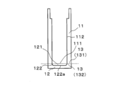
- the molding mold according to the embodiment of the present disclosure will be described with reference to FIGS. 1 and 2.
- the molding die 1 according to the embodiment shown in FIG. 1 includes a tubular portion 11 and a base portion 12.
- the material of the tubular portion 11 included in the molding die 1 according to the embodiment is not limited.
- the material of the tubular portion 11 include ceramics containing aluminum oxide, silicon carbide, or silicon nitride as a main component.
- the molding die is preferably formed of ceramics containing aluminum oxide as a main component. This is because when the molding die is manufactured, processing such as polishing and grinding is easy and the primary raw material is inexpensive.
- the ceramic used for the tubular portion 11 is referred to as "first ceramic" for convenience.
- the size of the tubular portion 11 is not particularly limited. It is appropriately set according to a desired member.
- the tubular portion 11 is cylindrical as shown in FIG. 1, the tubular portion 11 has, for example, an outer diameter of 32 mm or more and 50 mm or less and an inner diameter of 25 mm or more and 30 mm or less.
- the tubular portion 11 has, for example, a length of 100 mm or more and 200 mm or less.
- the base portion 12 included in the molding mold 1 according to the embodiment is provided so as to seal one end of the tubular portion 11.
- the outer diameter of the base portion 12 is preferably substantially the same as the outer diameter of the tubular portion 11, and may be large. Specifically, as shown in FIG.
- the shape of the opening 121 of the base 12 and the shape of the opening 111 of the tubular portion 11 of the base 12 match, and the thickness of the inner wall surface 122 of the base 12 and the tubular portion 11 It is preferable that the tubular portion 11 is provided so as to match the thickness of the inner wall surface 112 of the above.
- the broken line shown in FIG. 2 indicates the facing surface 13 between the tubular portion 11 and the base portion 12.
- the inner diameter ID 2 of the second facing surface 132 facing the tubular portion 11 of the base portion 12 is smaller than the inner diameter ID 1 of the first facing surface 131 facing the base portion 12 of the tubular portion 11.
- the difference between the inner diameter ID 2 and the inner diameter ID 1 is, for example, 0.2 mm or more and 0.5 mm or less.
- the material of the base 12 included in the molding mold 1 according to the embodiment is not limited.
- the material adopted for the above-mentioned tubular portion 11 can be mentioned, and it is preferable that the tubular portion 11 and the base portion 12 have the same main component.
- the material of the base portion 12 is preferably ceramics as in the case of the tubular portion 11.
- the ceramic used for the base 12 is referred to as "second ceramic" for convenience.
- the first ceramics and the second ceramics may be ceramics having the same main component or different main components.
- the "main component” means a component that occupies 80% by mass or more in a total of 100% by mass of the components constituting the ceramics.
- Each component contained in the ceramics may be identified by an X-ray diffractometer using CuK ⁇ rays.
- the content of each component may be determined by, for example, an ICP (Inductively Coupled Plasma) emission spectroscopic analyzer or a fluorescent X-ray analyzer.
- the shape of the base portion 12 is not limited as long as it can seal one end of the tubular portion 11.
- the base portion 12 included in the molding die 1 according to the embodiment has a concave shape that opens toward the tubular portion 11.
- the inner wall surface of the base portion 12 having a concave shape may be inclined from the opening 121 to the inner wall bottom portion 122a, and the inclination may be rounded.
- the inside of the tubular portion 11 and the inside of the base portion 12 are ground or polished into a shape corresponding to a desired member.
- the cutting level difference R ⁇ c 1 in the roughness curve of the inner wall surface 112 of the tubular portion 11 is smaller than the cutting level difference R ⁇ c 2 in the roughness curve of the inner wall bottom portion 122a of the base portion 12.
- the cutting level difference R ⁇ c in the roughness curve is in the height direction of the cutting levels C (Rrm1) and C (Rrm2) corresponding to the load length ratios Rmr1 and Rmr2 in the roughness curve defined in JIS B0601: 2001, respectively. It is an index showing the difference, and the smaller the value, the smoother the surface with less unevenness. That is, it is shown that the inner wall surface 112 of the tubular portion 11 has less unevenness and is smoother than the inner wall bottom portion 122a of the base portion 12.
- the “cutting level difference R ⁇ c 1 ” refers to the cutting level at a load length ratio of 25% in the roughness curve for the inner wall surface 112 of the tubular portion 11 and the load length of 75% in the roughness curve. It means the difference from the cutting level in the graduation.
- the “cutting level difference R ⁇ c 2 ” refers to the cutting level at the load length ratio of 25% in the roughness curve for the inner wall bottom portion 122a of the base portion 12 and the load length of 75% in the roughness curve. It means the difference from the cutting level in the graduation.
- the cutting level difference R ⁇ c 1 in the roughness curve of the inner wall surface 112 of the tubular portion 11 is smaller than the cutting level difference R ⁇ c 2 in the roughness curve of the inner wall bottom portion 122a of the base portion 12. Therefore, the inner wall surface 112 of the tubular portion 11 has less unevenness and is smoother than the inner wall bottom portion 122a of the base portion 12.
- a cylindrical substrate for a photoconductor for electrophotographic, a roller bearing roller, a sliding bearing of a roller follower, a cylindrical case accommodating a filter, and the like (hereinafter, these members are simply referred to as "for electrophotographic". It may be described as "cylindrical substrate for photoconductor"), and it can be applied to a member whose outer wall surface is required to have a surface texture (cutting level difference R ⁇ c) having higher accuracy than the end face.
- the size of the portion in contact with the base 12 of the molded body is shorter than that of the portion in contact with the tubular portion 11 of the molded body. .. Therefore, the shrinkage difference after the heat treatment is small. As a result, the portion in contact with the base portion 12 of the molded product is likely to be fixed to the base portion 12, and the releasability is lowered. Therefore, the cutting level difference R ⁇ c1 in the roughness curve of the inner wall surface 112 of the tubular portion 11 is made smaller than the cutting level difference R ⁇ c2 in the roughness curve of the inner wall bottom portion 122a of the base portion 12.
- the difference is not limited.
- the difference between the cutting level difference R ⁇ c 1 and the cutting level difference R ⁇ c 2 may be 0.2 ⁇ m or more. ..
- the inner wall surface 112 of the tubular portion 11 is smoother with less unevenness than the inner wall bottom portion 122a of the base portion 12. Can be.
- the cutting level difference R ⁇ c 2 of the inner wall bottom portion 122a which is difficult to clean, becomes large, and the hydrophilicity of the inner wall bottom portion 122a is higher than that of the inner wall surface 112, so that the cleaning efficiency is improved.
- a member such as a cylindrical substrate for an electrophotographic photosensitive member, which requires a surface texture (cutting level difference R ⁇ c) in which the outer wall surface has a higher accuracy than the end face.
- the cutting level difference R ⁇ c 2 of the inner wall bottom portion 122a is, for example, 0.6 ⁇ m or more and 2.5 ⁇ m or less.
- the hydrophilicity is improved, so that the cleaning efficiency is improved.
- the cutting level difference R ⁇ c 2 is 2.5 ⁇ m or less, the possibility that the powder separated from the molded body adheres to the valley bottom on the surface of the inner wall bottom portion 122a is reduced, and continuous molding of the molded body is facilitated.
- the contact angle with pure water can be, for example, 45 ° or less.
- the arithmetic average roughness Ra 1 of the inner wall surface 112 of the tubular portion 11 and the arithmetic mean roughness Ra 2 of the inner wall bottom portion 122a of the base portion 12 are not limited.
- the surface texture of the outer wall surface is controlled with high precision while maintaining good releasability of the base 12 (bottomed cylinder).
- the arithmetic mean roughness Ra 1 of the inner wall surface 112 of the tubular portion 11 is smaller than the arithmetic average roughness Ra 2 of the inner wall bottom portion 122a of the base portion 12 in that it is easy to obtain a columnar member (including the shape). Good.
- the difference between the arithmetic mean roughness Ra 1 and the arithmetic average roughness Ra 2 is preferably 0.2 ⁇ m or more.
- the arithmetic mean roughness Ra 2 of the inner wall bottom portion 122a is, for example, 0.6 ⁇ m or more and 1.6 ⁇ m or less.
- the arithmetic average roughness Ra 2 is 0.6 ⁇ m or more, the hydrophilicity is improved, so that the cleaning efficiency is further improved.
- the arithmetic mean roughness Ra 2 is 1.6 ⁇ m or less, the possibility that the powder separated from the molded body adheres to the valley bottom on the surface of the inner wall bottom portion 122a is reduced, and the continuous molding of the molded body is further facilitated.
- the cutting level difference R ⁇ c 2 is 0.6 ⁇ m or more, the contact angle with pure water can be, for example, 40 ° or less.
- the cutting level difference R ⁇ c 1 may be smaller than the cutting level difference R ⁇ c 3 in the roughness curve of the inner wall surface 122 of the base portion 12 which is inclined from the opening to the inner wall bottom portion 122a.
- the difference between the cutting level difference R ⁇ c 1 and the cutting level difference R ⁇ c 3 may be 0.2 ⁇ m or more.
- the cutting level difference R ⁇ c 3 may be 0.6 ⁇ m or more and 2.5 ⁇ m or less.
- the cutting level difference R ⁇ c 1 , the cutting level difference R ⁇ c 2 , the cutting level difference R ⁇ c 3 , the arithmetic mean roughness Ra 1 , the arithmetic mean roughness Ra 2, and the arithmetic mean roughness Ra 3 are based on JIS B 0601: 2001, and are lasers. It can be measured using a microscope (manufactured by Keyence Co., Ltd., ultra-deep color 3D shape measuring microscope (VK-X1100 or its successor model)).
- the measurement conditions are coaxial epi-illumination, no cutoff value ⁇ s, cutoff value ⁇ c of 0.08 mm, and correction of the termination effect, from the inner wall surface 112, the inner wall bottom 122a, or the inner wall surface 122 to be measured.
- the surface roughness may be measured by setting the measurement range per location to 2792 ⁇ m ⁇ 2090 ⁇ m and drawing four lines to be measured along the longitudinal direction of the measurement range for each measurement range.
- the length per line to be measured is, for example, 2640 ⁇ m.
- the method for manufacturing the molding mold 1 according to the embodiment is not limited.
- the molding die 1 according to the embodiment can be obtained by, for example, the following procedure.
- tubular portion 11 and the base portion 12 are made of ceramics containing aluminum oxide as a main component
- Aluminum oxide powder purity of 99.9% by mass or more
- each powder of magnesium hydroxide, silicon oxide and calcium carbonate are put into a pulverizing mill together with a solvent (ion-exchanged water).
- a solvent ion-exchanged water.
- an organic binder and a dispersant for dispersing the aluminum oxide powder are added and mixed to obtain a slurry.
- the content of magnesium hydroxide powder in a total of 100% by mass of the powder is 0.3 to 0.42% by mass
- the content of silicon oxide powder is 0.5 to 0.8% by mass
- that of calcium carbonate powder is 0.060 to 0.1% by mass
- the balance is aluminum oxide powder and unavoidable impurities.
- Organic binders are acrylic emulsions, polyvinyl alcohols, polyethylene glycols, polyethylene oxides, etc.
- the slurry is spray granulated to obtain granules.
- the tubular portion 11 first, the granules are filled in a mold, and then the granules are pressurized at a molding pressure of 78 MPa or more and 128 MPa or less to obtain a tubular molded body.
- the first ceramics which is a precursor of the tubular portion 11 can be obtained.
- the inner wall surface 112 of the tubular portion 11 is obtained, for example, by grinding the inner wall surface of the first ceramics using a honing machine.
- a grindstone containing diamond abrasive grains having a particle size of # 800 to # 1200 defined by JIS R 6001-2: 2017 may be mounted on a honing machine and ground.
- the granules are filled in a mold, and then the granules are pressurized at a molding pressure of 78 MPa or more and 128 MPa or less to obtain a plate-shaped molded product.
- a molding pressure of 78 MPa or more and 128 MPa or less By cutting the upper surface of this molded body, a portion to be the inner wall bottom portion 112a of the base portion 12 is formed after firing.
- the machined molded product By holding the machined molded product at a temperature of 1500 ° C. or higher and 1700 ° C. or lower and a time of 4 hours or more and 6 hours or less, the second ceramics which is a precursor of the base 12 can be obtained.
- diamond paste to the buff and polish the bottom of the inner wall of the second ceramics to the extent that burrs are removed.
- a paste in which diamond powder having an average particle size of 1 ⁇ m or more and 4 ⁇ m or less is dispersed in an organic solvent may be used.
- the cutting level difference R ⁇ c 1 on the roughness curve of the inner wall surface 112 of the tubular portion 11 is smaller than the cutting level difference R ⁇ c 2 on the roughness curve of the inner wall bottom 112a of the base portion 12. Can be obtained.
- the ceramics are not limited, and examples thereof include ceramics containing aluminum oxide as a main component, as described above, and ceramics containing silicon carbide or silicon nitride as a main component.
- the ceramics are as described above, and the second ceramic may be the same ceramic as the first ceramic or may be a different ceramic. Considering the processed surface and the working surface, the first ceramics and the second ceramics are preferably ceramics having the same main component.
- the second ceramic is polished by the method described above.
- a grindstone containing diamond abrasive grains having a particle size of # 800 to # 1000 may be mounted on the honing machine to grind the inner wall surface of the first ceramics.
- the following method can be mentioned. .. First, a grindstone containing diamond abrasive grains having the above particle size of # 800 to # 1200 is mounted on a honing machine to grind the inner wall surface of the first ceramics. Next, the bottom of the inner wall of the second ceramics may be polished using a paste in which diamond powder having an average particle size of 2 ⁇ m or more and 4 ⁇ m or less is dispersed in an organic solvent.
- the following method can be mentioned.
- a grindstone containing diamond abrasive grains having the above particle size of # 800 to # 1000 is mounted on a honing machine to grind the inner wall surface of the first ceramics.
- the bottom of the inner wall of the second ceramics may be polished using a paste in which diamond powder having an average particle size of 2 ⁇ m or more and 4 ⁇ m or less is dispersed in an organic solvent.
- the outer diameter of the base portion 12 is substantially the same as the outer diameter of the tubular portion 11. Further, the shape of the opening 121 of the base portion 12 and the shape of the opening 111 of the tubular portion 11 match, and the thickness of the inner wall surface 122 of the base portion 12 and the thickness of the inner wall surface 112 of the tubular portion 11 match.
- the joining method between the tubular portion 11 and the base portion 12 is not limited, and examples thereof include the following methods (diffusion joining).
- the method of adhering water is not limited, and for example, water is sprayed on at least one of the first facing surface 131 and the second facing surface 132, water is applied with a brush, or the water is directly immersed in water. The method etc. can be mentioned.
- a slurry containing diamond having an average particle size of 0.5 ⁇ m or more and 3 ⁇ m or less is placed on a copper, tin, or tin-lead alloy lapping machine every predetermined time. Is obtained by polishing the end face of the tubular portion 11 facing the base portion 12.
- a slurry containing diamond having an average particle size of 0.5 ⁇ m or more and 3 ⁇ m or less is put on a copper, tin, or tin-lead alloy lapping machine every predetermined time. Is obtained by polishing the end face of the base portion 12 facing the tubular portion 11.
- the arithmetic mean roughness Ra of each of the first facing surface 131 and the second facing surface 132 is, for example, 0.2 ⁇ m or less.
- the first facing surface 131 and the second facing surface 132 are adsorbed.
- the heat treatment is performed while pressing the adsorption surface.
- the strength of pressing is not limited, and is appropriately set according to the size and material of the tubular portion 11 and the base portion 12. Specifically, it is preferable to press with a pressure of about 1 kgf to 5 kgf.
- the heat treatment is also appropriately set according to the size and material of the tubular portion 11 and the base portion 12. Specifically, it is preferable to heat-treat at 1000 ° C. or higher and 1800 ° C. or lower.
- the heat treatment may be performed for, for example, about 30 minutes to 120 minutes. In this way, the molding die 1 according to the embodiment is manufactured.
- the tubular portion 11 has a cylindrical shape.
- the tubular portion is not limited to a cylindrical shape, and may be an elliptical tubular shape depending on the shape of a desired member, and a square cylinder having a cross section of a triangular shape, a square shape, a pentagonal shape, a hexagonal shape, or the like. It may have a shape.
- the above-mentioned molding die 1 has a concave shape in which the base portion 12 opens toward the tubular portion 11.
- the shape of the base is not limited to the concave shape, and may be appropriately set according to the shape of the desired member, and may be a flat plate shape such as a bottom plate.
- the inner wall surface 122 of the base portion 12 has a rounded inclination from the opening 121 to the inner wall bottom portion 122a.
- the inclination does not have to have a rounded shape, and is appropriately set according to the desired shape of the member.
- the inner wall surface 122 of the base portion 12 may be vertical from the opening 121 to the inner wall bottom portion 122a.
Landscapes
- Engineering & Computer Science (AREA)
- Mechanical Engineering (AREA)
- Manufacturing & Machinery (AREA)
- Chemical & Material Sciences (AREA)
- Ceramic Engineering (AREA)
- Materials Engineering (AREA)
- Structural Engineering (AREA)
- Organic Chemistry (AREA)
- Moulds For Moulding Plastics Or The Like (AREA)
- Powder Metallurgy (AREA)
- Press-Shaping Or Shaping Using Conveyers (AREA)
Priority Applications (4)
| Application Number | Priority Date | Filing Date | Title |
|---|---|---|---|
| KR1020227002061A KR102665048B1 (ko) | 2019-07-25 | 2020-07-16 | 성형 몰드 및 그 제조 방법 |
| JP2021533985A JP7221394B2 (ja) | 2019-07-25 | 2020-07-16 | 成形型およびその製造方法 |
| CN202080052380.7A CN114126784B (zh) | 2019-07-25 | 2020-07-16 | 成形模具及其制造方法 |
| US17/629,120 US11958263B2 (en) | 2019-07-25 | 2020-07-16 | Molding die and manufacturing method for the same |
Applications Claiming Priority (2)
| Application Number | Priority Date | Filing Date | Title |
|---|---|---|---|
| JP2019136950 | 2019-07-25 | ||
| JP2019-136950 | 2019-07-25 |
Publications (1)
| Publication Number | Publication Date |
|---|---|
| WO2021015092A1 true WO2021015092A1 (ja) | 2021-01-28 |
Family
ID=74192583
Family Applications (1)
| Application Number | Title | Priority Date | Filing Date |
|---|---|---|---|
| PCT/JP2020/027673 Ceased WO2021015092A1 (ja) | 2019-07-25 | 2020-07-16 | 成形型およびその製造方法 |
Country Status (5)
| Country | Link |
|---|---|
| US (1) | US11958263B2 (https=) |
| JP (1) | JP7221394B2 (https=) |
| KR (1) | KR102665048B1 (https=) |
| CN (1) | CN114126784B (https=) |
| WO (1) | WO2021015092A1 (https=) |
Cited By (1)
| Publication number | Priority date | Publication date | Assignee | Title |
|---|---|---|---|---|
| JPWO2023140147A1 (https=) * | 2022-01-18 | 2023-07-27 |
Citations (4)
| Publication number | Priority date | Publication date | Assignee | Title |
|---|---|---|---|---|
| JPH1142618A (ja) * | 1997-07-25 | 1999-02-16 | Toyo Chem Co Ltd | 無機硬化組成物成型方法 |
| JP2008272774A (ja) * | 2007-04-26 | 2008-11-13 | Sumitomo Electric Ind Ltd | 粉末成形用金型および該粉末成形用金型で成形された圧粉成形体 |
| JP2018019017A (ja) * | 2016-07-29 | 2018-02-01 | 京セラ株式会社 | 載置用部材 |
| WO2018198983A1 (ja) * | 2017-04-27 | 2018-11-01 | 京セラ株式会社 | 装飾部品 |
Family Cites Families (10)
| Publication number | Priority date | Publication date | Assignee | Title |
|---|---|---|---|---|
| JP2002195266A (ja) | 2000-12-27 | 2002-07-10 | Ntn Corp | ころ軸受 |
| JP4062096B2 (ja) | 2002-12-27 | 2008-03-19 | 株式会社ジェイテクト | ローラフォロアおよびローラフォロアを有するエンジンの動弁機構 |
| JP3803675B2 (ja) * | 2004-03-05 | 2006-08-02 | 株式会社東芝 | 二次加工用タングステン素材の製造方法 |
| DE102006024905A1 (de) * | 2006-05-24 | 2007-11-29 | Endress + Hauser Conducta Gesellschaft für Mess- und Regeltechnik mbH + Co. KG | Formdichtung, Dichtungsanordnung und Prozesssensor mit einer solchen Dichtungsanordnung |
| JP2008272778A (ja) * | 2007-04-26 | 2008-11-13 | Sumitomo Electric Ind Ltd | 金型、該金型で成形された圧粉成形体および該金型を用いた圧粉成形体の製造方法 |
| CN110021476B (zh) * | 2014-03-13 | 2021-10-22 | 日立金属株式会社 | 压粉磁芯的制造方法以及压粉磁芯 |
| JP6555679B2 (ja) * | 2014-12-12 | 2019-08-07 | 住友電工焼結合金株式会社 | 鉄系焼結部品の製造方法、及び鉄系焼結部品 |
| JP6708460B2 (ja) * | 2016-03-30 | 2020-06-10 | 京セラ株式会社 | 接合体の製造方法 |
| EP3550383B9 (en) * | 2016-11-29 | 2024-08-14 | Kyocera Corporation | Timepiece case |
| EP3950263B1 (en) | 2019-04-04 | 2026-02-11 | Nissei Asb Machine Co., Ltd. | Method for producing resin container, injection core mold, mold for injection molding, and device for producing resin container |
-
2020
- 2020-07-16 JP JP2021533985A patent/JP7221394B2/ja active Active
- 2020-07-16 WO PCT/JP2020/027673 patent/WO2021015092A1/ja not_active Ceased
- 2020-07-16 CN CN202080052380.7A patent/CN114126784B/zh active Active
- 2020-07-16 KR KR1020227002061A patent/KR102665048B1/ko active Active
- 2020-07-16 US US17/629,120 patent/US11958263B2/en active Active
Patent Citations (4)
| Publication number | Priority date | Publication date | Assignee | Title |
|---|---|---|---|---|
| JPH1142618A (ja) * | 1997-07-25 | 1999-02-16 | Toyo Chem Co Ltd | 無機硬化組成物成型方法 |
| JP2008272774A (ja) * | 2007-04-26 | 2008-11-13 | Sumitomo Electric Ind Ltd | 粉末成形用金型および該粉末成形用金型で成形された圧粉成形体 |
| JP2018019017A (ja) * | 2016-07-29 | 2018-02-01 | 京セラ株式会社 | 載置用部材 |
| WO2018198983A1 (ja) * | 2017-04-27 | 2018-11-01 | 京セラ株式会社 | 装飾部品 |
Cited By (4)
| Publication number | Priority date | Publication date | Assignee | Title |
|---|---|---|---|---|
| JPWO2023140147A1 (https=) * | 2022-01-18 | 2023-07-27 | ||
| WO2023140147A1 (ja) * | 2022-01-18 | 2023-07-27 | 京セラ株式会社 | 核磁気共鳴装置用サンプルチューブ |
| JP7678149B2 (ja) | 2022-01-18 | 2025-05-15 | 京セラ株式会社 | 核磁気共鳴装置用サンプルチューブ |
| EP4467273A4 (en) * | 2022-01-18 | 2025-12-24 | Kyocera Corp | SAMPLE TUBE FOR NUCLEAR MAGNETIC RESONANCE EQUIPMENT |
Also Published As
| Publication number | Publication date |
|---|---|
| CN114126784A (zh) | 2022-03-01 |
| JPWO2021015092A1 (https=) | 2021-01-28 |
| CN114126784B (zh) | 2023-09-19 |
| KR102665048B1 (ko) | 2024-05-13 |
| US11958263B2 (en) | 2024-04-16 |
| JP7221394B2 (ja) | 2023-02-13 |
| US20220281200A1 (en) | 2022-09-08 |
| KR20220024798A (ko) | 2022-03-03 |
Similar Documents
| Publication | Publication Date | Title |
|---|---|---|
| CN1130274C (zh) | 研磨工具 | |
| US20160303704A1 (en) | Grinding Tool | |
| KR102253560B1 (ko) | 절삭 공구 | |
| CN108352319B (zh) | 喷淋板、半导体制造装置以及喷淋板的制造方法 | |
| JP2010089170A (ja) | 球状体の研磨装置、球状体の研磨方法および球状部材の製造方法 | |
| CN101049676A (zh) | G3级氮化硅球加工工艺 | |
| JP2011093789A (ja) | セラミックボール素球、セラミックボール素球成形用金型およびセラミックボール素球の製造方法 | |
| CN1795078A (zh) | 瓷胶结砂轮及其制造方法 | |
| JP6687231B2 (ja) | 研磨工具及びその製造方法並びに研磨物の製造方法 | |
| WO2021015092A1 (ja) | 成形型およびその製造方法 | |
| JP2003136410A (ja) | 超砥粒ビトリファイドボンド砥石 | |
| TW201941870A (zh) | 樹脂型磨削磨石 | |
| JP7507899B2 (ja) | 液体収容容器およびその製造方法 | |
| TW528658B (en) | Beveling wheel for processing silicon wafer outer periphery | |
| US20020110661A1 (en) | Abrasive molding and abrasive disc provided with same | |
| KR20200066975A (ko) | 스마트폰용 유리박판 연마툴 | |
| KR102573502B1 (ko) | 전자선 묘화 장치용 프레임 부재 및 전자선 묘화 장치 | |
| JPH06229422A (ja) | セラミック製ころがり軸受部材の製造方法 | |
| JP4874597B2 (ja) | 研削砥石の製造方法 | |
| EP4534868A1 (en) | Material for ceramic ball, method for producing ceramic ball using same, and ceramic ball | |
| JP7598940B2 (ja) | クランプ用治具および洗浄装置 | |
| JP4890883B2 (ja) | SiOx粉を含む成形体および砥石、それを用いた研削方法 | |
| JP2021050127A (ja) | セラミック接合体 | |
| WO2025234334A1 (ja) | アルミナ焼結体、アルミナ焼結体の製造方法、部材およびプラズマ処理装置 | |
| JP2007196317A (ja) | ビトリファイド超仕上砥石の製造方法 |
Legal Events
| Date | Code | Title | Description |
|---|---|---|---|
| 121 | Ep: the epo has been informed by wipo that ep was designated in this application |
Ref document number: 20843919 Country of ref document: EP Kind code of ref document: A1 |
|
| ENP | Entry into the national phase |
Ref document number: 2021533985 Country of ref document: JP Kind code of ref document: A |
|
| ENP | Entry into the national phase |
Ref document number: 20227002061 Country of ref document: KR Kind code of ref document: A |
|
| NENP | Non-entry into the national phase |
Ref country code: DE |
|
| 122 | Ep: pct application non-entry in european phase |
Ref document number: 20843919 Country of ref document: EP Kind code of ref document: A1 |